Embed Size (px)
Citation preview
Advanced Steel Construction Vol. 3, No. 1, pp. 512-529 (2007) 512
SIMPLIFIED APPROACH TO EVALUATION OF STEEL BEAM-COLUMN FIRE RESISTANCE
M. Maślak
Assistant Professor, Department of Civil Engineering,
Cracow University of Technology, 31-155 Cracow, Warszawska 24, Poland (Corresponding author: E-mail: [email protected])
Received: 7 September 2006; Revised: 21 October 2006; Accepted: 25 October 2006
ABSTRACT: The approach, presented in this paper, allows a designer to assess the value of steel member fire resistance if unlimited thermal deformations are restrained. The beam analysed in the example is subject to bending in persistent design situation; whereas, under the influence of fire temperature, additional compression force occurs. The fire resistance of structural element depends on the degree of restraints. Large flexural stiffness of columns which bound the beam leads to the relatively small value of beam fire resistance. Alternatively, if their stiffness is lower (deformability is greater) the reduction of member fire resistance in relation to the beam with fully unrestrained thermal deformations is also softer. Results obtained in the presented analysis should be interpreted only as an approximation of real values. More accurate solutions can be reckoned only if rheological effects, particularly creep of steel, are taken into account.
Keywords: beam-column; fire; temperature; fire resistance; thermal deformation
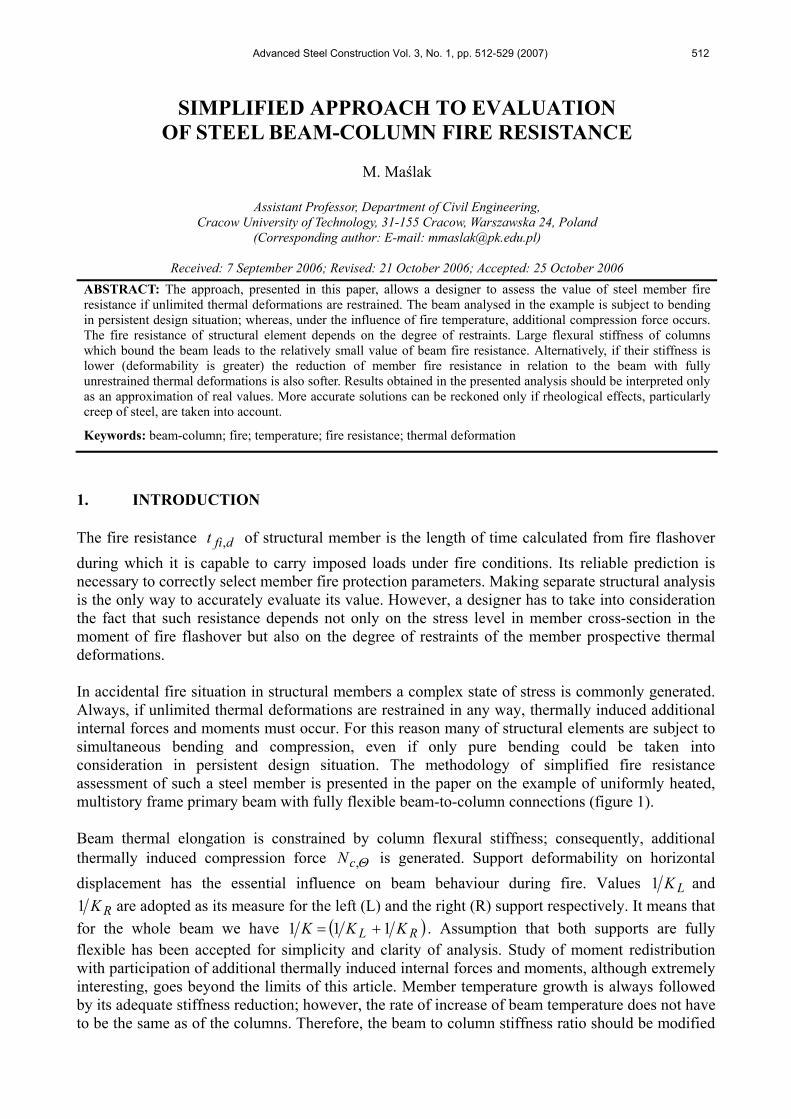
1. INTRODUCTION The fire resistance dfit , of structural member is the length of time calculated from fire flashover during which it is capable to carry imposed loads under fire conditions. Its reliable prediction is necessary to correctly select member fire protection parameters. Making separate structural analysis is the only way to accurately evaluate its value. However, a designer has to take into consideration the fact that such resistance depends not only on the stress level in member cross-section in the moment of fire flashover but also on the degree of restraints of the member prospective thermal deformations. In accidental fire situation in structural members a complex state of stress is commonly generated. Always, if unlimited thermal deformations are restrained in any way, thermally induced additional internal forces and moments must occur. For this reason many of structural elements are subject to simultaneous bending and compression, even if only pure bending could be taken into consideration in persistent design situation. The methodology of simplified fire resistance assessment of such a steel member is presented in the paper on the example of uniformly heated, multistory frame primary beam with fully flexible beam-to-column connections (figure 1). Beam thermal elongation is constrained by column flexural stiffness; consequently, additional thermally induced compression force Θ,cN is generated. Support deformability on horizontal displacement has the essential influence on beam behaviour during fire. Values LK1 and
RK1 are adopted as its measure for the left (L) and the right (R) support respectively. It means that for the whole beam we have ( )RL KKK 111 += . Assumption that both supports are fully flexible has been accepted for simplicity and clarity of analysis. Study of moment redistribution with participation of additional thermally induced internal forces and moments, although extremely interesting, goes beyond the limits of this article. Member temperature growth is always followed by its adequate stiffness reduction; however, the rate of increase of beam temperature does not have to be the same as of the columns. Therefore, the beam to column stiffness ratio should be modified
M. Maślak 513
in particular fire moments fit . Nevertheless, if bending moment caused by all imposed loads (without any thermal influences) summed according to accidental load combination rule is not distributed from the beam to adjacent columns, its value does not depend on the beam temperature and remains constant in the whole of fire duration (any load changes generated by evacuation of occupants or furnishings combustion are not taken into consideration). Additional simplified assumption has been made that the steel temperature aΘ distribution for particular fire moment fit is uniform not only in each beam section but also along the whole of its length. In general frame beams adjoin massive reinforced concrete floor slab with a great thermal capacity. For this reason in real fires their top flange temperature is slightly lower than a bottom one. Such a gradient steel temperature distribution gives additional member deflections which can reach very considerable values. The separate, more precise discussion is necessary to study this effect; however, let us draw attention to one important fact: compression force Θ,cN development in fire is the result of restraints of member thermal deformations; whereas, oppositely directed tension force Θ,tN is activated as a consequence of simultaneous deflection growth. Paradoxically such a tension force reduces deflection from which it is induced. Theoretically it is even possible that ΘΘ > ,, ct NN .
Figure 1. Multistory Frame Primary Beam Analysed in the Paper.
2. GENERALIZED STABILITY FORMULA In practical applications formulae relevant to member analysis in ambient temperature can also be applied when fully developed fire is taken into account, providing that reduced values of yield stress Θ,yf and elasticity modulus ΘE of steel are considered. This typical standard approach
seems to be acceptable for the particular fire moments fit if member temperature ( )fia tΘ can be
explicitly determined, because the value of compression force Θ,cN can be then calculated on the basis of strain equilibrium condition. Both load bearing capacity and stability conditions are checked for particular fit , until the limit value dfit , , called member fire resistance, is found. Fire
resistance limit state is reached if the most unfavourable design load effect Θ,,diE , determined in accordance with accidental load combination rule, rises to the level of member load bearing capacity reduced in given steel temperature Θ,,diR , in other words when
514 Simplified Approach to Evaluation of Steel Beam-Column Fire Resistance
1,,,,, == ΘΘΘρ didii RE . At present one cannot definitely say that existing stability conditions relevant to beam-column analysis in ambient temperature, proposed by various authors, are verified enough. Complexity of the problem still generates intense and open discussion. The author prefers in this field the application of elastic-plastic stability formula which is based on the concept of moment equivalent
xx Mβ (Boissonnade et al. [2]), and is written in a form well known from German DIN 18800 and also Polish PN-90/B-03200 standards. The fully developed fire situation will be taken into account if such a formula is generalized (values dependent on steel temperature aΘ are marked with the bottom index Θ ):
1,,,
,
,,,1 ≤++= Θ
ΘΘ
Θ
ΘΘ
ΘΘ Δ
ϕβ
ϕρ x
RxL
xx
Rcx
cMM
NN
(1)
where:
( ) ( ) 1,025,11,
,
,
,2,,
2,
2,
,,
,
,
,, ≤≈⎟
⎟⎠
⎞⎜⎜⎝
⎛−=
Θ
Θ
Θ
ΘΘΘΘΘ
ΘΘ
Θ
Θ
ΘΘ
βλϕλϕ
ϕΔ
Rc
c
Rx
xxxxxx
Rcx
c
Rc
cx N
NM
MN
NNN
(2)
The left part of Eq. (2) origins from the German standard, whereas its right part from the Polish one. Simple generalization of standard stability formulae leads to the assessments consistent with the results of numerical modelling (Valente [11], Vila Real et al. [12], Huang et al. [4], Yin et al. [14], Vila Real et al. [13]). They have also received separate confirmation in the experiment (Liu et al. [5]). Two other inequalities are usually connected with Eq. (1). In case of 1<βx the cNM −
interaction cross-section load bearing capacity Θρ ,2 limitation can be crucial:
1,,
,
,
,,2 ≤+=
ΘΘ
Θ
Θ
ΘΘ ϕ
ρRxL
x
Rc
cM
MNN
(3)
Moreover, the elimination of weak axis buckling ability is extremely important:
1,,
,,3 ≤=
ΘΘ
ΘΘ ϕ
ρRcy
cN
N (4)
Eq. (1), Eq. (3) and Eq. (4) allow to find particular values of beam-column fire resistance, 1,,dfit ,
2,,dfit and 3,,dfit , respectively. The smallest of these three means its conclusive value. 3. MEMBER LOAD BEARING CAPACITY UNDER FIRE CONDITIONS Coefficients Θ,yk and Θ,Ek are commonly used as a measure of relative reduction of yield
M. Maślak 515
stress yf and elasticity modulus E , respectively. If the rule that partial safety factors remain
constant in the whole of fire duration can be accepted, then we have ( 33,1=crγ is well known from PN-90/B-03200 partial safety factor for critical stresses):
dyM
yy
M
yd fk
fkff Θ
ΘΘΘ γγ ,
,,, === (5)
dEcr
E
crd Ek
EkEE Θ
ΘΘΘ γγ ,
,, === (6)
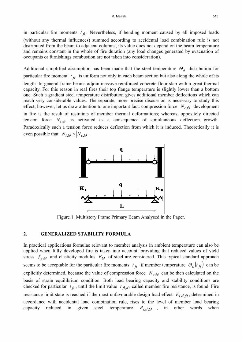
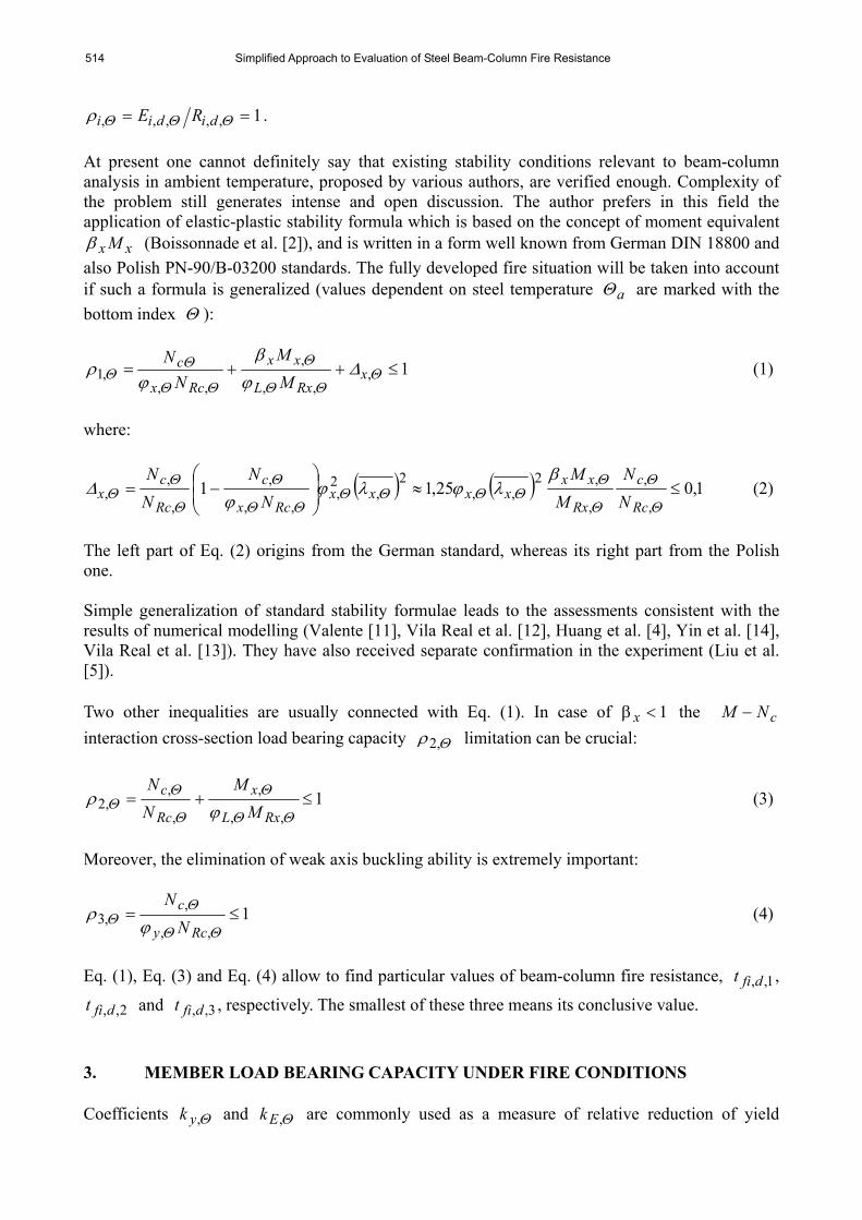
Accurate determination of Θ,yk and Θ,Ek values is not simple because of a great scatter of existing experimental results. Usually values proposed by EN 1993-1-2 standard are applied (table 1 and figure 2).
Table 1. Reduction Coefficients Θ,yk and Θ,Ek According to EN 1993-1-2.
aΘ ][ Co Θ,yk Θ,Ek
≤ 100 1.00 1.00 200 1.00 0.90 300 1.00 0.80 400 1.00 0.70 500 0.78 0.60 600 0.47 0.31 700 0.23 0.13 800 0.11 0.09 900 0.06 0.0675 1000 0.04 0.045
Figure 2. Relative Reduction of Yield Stress and Elasticity Modulus of
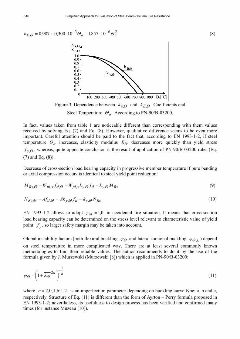
Steel Under Fire Conditions According to EN 1993-1-2. On the other hand, in the Polish PN-90/B-03200 standard function relationships are recommended (figure 3):
263, 10590,110197,0022,1 aayk ΘΘΘ
−− ⋅−⋅−= (7)
516 Simplified Approach to Evaluation of Steel Beam-Column Fire Resistance
263, 10857,110300,0987,0 aaEk ΘΘΘ
−− ⋅−⋅+= (8)
Figure 3. Dependence between Θ,yk and Θ,Ek Coefficients and
Steel Temperature aΘ According to PN-90/B-03200. In fact, values taken from table 1 are noticeable different than corresponding with them values received by solving Eq. (7) and Eq. (8). However, qualitative difference seems to be even more important. Careful attention should be paid to the fact that, according to EN 1993-1-2, if steel temperature aΘ increases, elasticity modulus ΘE decreases more quickly than yield stress
Θ,yf ; whereas, quite opposite conclusion is the result of application of PN-90/B-03200 rules (Eq. (7) and Eq. (8)). Decrease of cross-section load bearing capacity in progressive member temperature if pure bending or axial compression occurs is identical to steel yield point reduction:
RxydyxpldxplRx MkfkWfWM ΘΘΘΘ ,,,,,, === (9)
RcydydRc NkfAkAfN ΘΘΘΘ ,,,, === (10)
EN 1993-1-2 allows to adopt 0,1=Mγ in accidental fire situation. It means that cross-section load bearing capacity can be determined on the stress level relevant to characteristic value of yield point yf , so larger safety margin may be taken into account. Global instability factors (both flexural buckling Θϕ and lateral-torsional buckling L,Θϕ ) depend on steel temperature in more complicated way. There are at least several commonly known methodologies to find their reliable values. The author recommends to do it by the use of the formula given by J. Murzewski (Murzewski [8]) which is applied in PN-90/B-03200:
nn1
21−⎟⎠⎞⎜
⎝⎛ += ΘΘ λϕ (11)
where 1,2 1,6; ;0,2=n is an imperfection parameter depending on buckling curve type: a, b and c, respectively. Structure of Eq. (11) is different than the form of Ayrton – Perry formula proposed in EN 1993-1-2; nevertheless, its usefulness to design process has been verified and confirmed many times (for instance Muzeau [10]).
M. Maślak 517
According to EN 1993-1-2 in accidental fire situation the definition of non-dimensional slenderness Θλ is revised (value of ( ) dp fE15,1π=λ the author suggests to calculate according to
PN-90/B-03200, correcting in this way lack of coefficient 33,1=γ cr in European recommendations). In fact the acceptance of the concept:
pddcry
E
dy
dE
d
dp f
Ef
Ekk
fkEk
fE
ψλπψγ
πππλΘ
Θ
Θ
Θ
Θ
ΘΘ =====
15,1,
,
,
,
,
,, (12)
leads to the formula:
ψλ
ψλλ
λλλΘ
Θ ===pp,
(13)
where ΘΘψ ,, yE kk= .
Substitution of Eq. (13) to Eq. (11) gives:
nnnn
121
2 11
−−
⎥⎥
⎦
⎤
⎢⎢
⎣
⎡
⎟⎟⎠
⎞⎜⎜⎝
⎛+=⎟
⎠⎞⎜
⎝⎛ +=
ψλλϕ ΘΘ (14)
Furthermore, considering the fact that according to EN 1993-1-2 instability factors are recommended to be determined if uniform imperfection parameter yf23565,0=α is assumed,
the author, by analogy, suggests using in Eq. (14) always the c - type buckling curve (in other words 2,1=n ), independently of the cross-section shape. It means that the value of Θϕ should be calculated in this way even if the other buckling curve has been taken into consideration in persistent design situation. Consequently, the ratio ( ) ϕϕΘ ΘΘ =am which is the measure of relative reduction of buckling instability factor in fire, is dependent on the type of buckling curve (a, b or c) taken to stability analysis without any thermal effects. Dependence of Θm ratio on steel temperature aΘ is shown in figure 4 (note that values of Θm are precisely calculated only for temperatures aΘ presented in table 1; in case of the intermediate aΘ values linear interpolation is applied). In PN-90/B-03200 the alternative methodology to calculate buckling instability factor Θϕ under fire conditions is proposed. Its value can be found directly from semi-empirical formula:
1
,
11
,
1111111111−−−
⎥⎥⎦
⎤
⎢⎢⎣
⎡⎟⎟⎠
⎞⎜⎜⎝
⎛−+=⎥
⎦
⎤⎢⎣
⎡⎟⎟⎠
⎞⎜⎜⎝
⎛−+=
⎥⎥⎦
⎤
⎢⎢⎣
⎡⎟⎟⎠
⎞⎜⎜⎝
⎛−+=
ΘΘΘΘ ϕϕϕϕ
Ed
dkE
EEE
(15)
in which ϕ is an analogous instability factor but determined without thermal effects, in other
518 Simplified Approach to Evaluation of Steel Beam-Column Fire Resistance
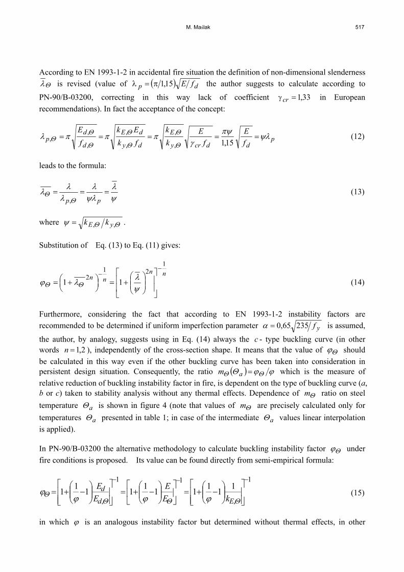
words, for non-dimensional slenderness pλλ=λ where ( ) dp fE15,1π=λ .
Figure 4. Relative Reduction ϕϕΘΘ =m of Buckling Instability Factor Under
Fire Conditions According to EN 1993-1-2 Approach. However, considering the fact that fire is an accidental design situation, the use of characteristic values of elasticity modulus γ= EEc and cEEc EkEkE ΘΘΘ =γ= ,,, seems to be more adequate (Maślak [7]). Then:
1
,
11
,,
1111111111−−−
⎥⎥⎦
⎤
⎢⎢⎣
⎡⎟⎟⎠
⎞⎜⎜⎝
⎛−+=
⎥⎥⎦
⎤
⎢⎢⎣
⎡⎟⎟⎠
⎞⎜⎜⎝
⎛−+=
⎥⎥⎦
⎤
⎢⎢⎣
⎡⎟⎟⎠
⎞⎜⎜⎝
⎛−+=
ΘΘΘΘ ϕϕϕ
ϕEccc
c
cc kE
EEE
(16)
Another partial safety factor for critical stresses γ , necessary to calculate characteristic value cE , is applied in Eq. (16). Its value has not been shown in PN-90/B-03200, but in author’s opinion the American recommendations in which value 14,1=γ has been adopted may be helpful in this field, because value 33,1=γ cr is there also assumed. Moreover, careful attention should also be paid to the fact that the factor cϕ has to be now determined in relation to corrected non-dimensional
slenderness cpc ,λλλ = , where:
pMdM
dcr
yyy
ccp f
EfE
fE
fE
λγγ
γγπ
γπ
γππλ 08,1
, ===== (17)
Let us notice that values cp,λ and pλ are equal each other only if 17,1=γM .
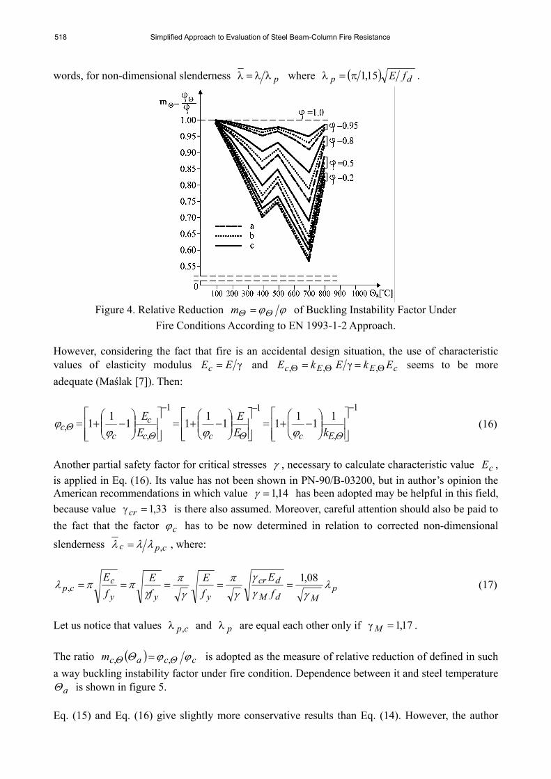
The ratio ( ) ccacm ϕϕΘ ΘΘ ,, = is adopted as the measure of relative reduction of defined in such a way buckling instability factor under fire condition. Dependence between it and steel temperature
aΘ is shown in figure 5. Eq. (15) and Eq. (16) give slightly more conservative results than Eq. (14). However, the author
M. Maślak 519
must underline the fact that both presented above methodologies to determine buckling instability factor under fire conditions are not compatible. Only values Θ,yk and Θ,Ek originating from Eq. (7) and Eq. (8) can be substitute to Eq. (15) and Eq. (16) because all formulae in this approach have been calibrated especially for them. On the other hand, application of Eq. (14) leads to correct results only if data from table 1 are taken into consideration (let us notice that according to Eq. (7) and Eq. (8) ΘΘ ,, Ey kk < which means that 1>ψ in Eq. (14) so it is inconsistent with the intuition).
Figure 5. Relative Reduction cccm ϕϕ ΘΘ ,, = of Buckling Instability
Factor According to PN-90/B-03200. Reminding one more approach proposed by J. Murzewski and M. Gwóźdź (Murzewski and Gwóźdź [9]) seems to be advisable in this place. They have postulated the application of elastic-plastic buckling theory. Such an analysis allowed them to generalize a typical formula proposed in PN-90/B-03200 for ambient temperature and persistent design situation:
ΘΘλϕΘnn1
21−⎟⎠⎞⎜
⎝⎛ += (18)
where:
α
Θ Θ ⎟⎟⎠
⎞⎜⎜⎝
⎛=
ann 175 (19)
Parameter Θn is here also an imperfection factor; however, it depends now on steel temperature. Values of an exponent α are collected in table 2 for the temperature interval
CC aoo 600300 ≤≤Θ and when buckling curves are determined by imperfection parameter n,
identically as in typical stability analysis made in ambient temperature.
Table 2. Exponents α for Particular Buckling Curves (Murzewski, J. and Gwóźdź, M.) Buckling curve a b c
n (according to PN-90/B-03200) 2.0 1.6 1.2 α 0.56 0.44 0.30
520 Simplified Approach to Evaluation of Steel Beam-Column Fire Resistance
The approach entirely similar to Eq. (12) may also be applied to determination of lateral-torsional buckling instability factor Θϕ ,L . If the member cross-section is bisymmetrical and dependence between Poisson’s ratio ν and steel temperature aΘ can be neglected, then for the floor beam analysed in the example it is possible to show:
crEcr MkM ΘΘ ,, = (20)
which means that:
ψλ
λΘ
Θ
Θ
ΘΘ
L
cr
R
E
y
cr
RL M
Mkk
MM
===,
,
,
,, 15,115,1 (21)
The analysis of more complex examples of member lateral-torsional buckling phenomenon under fire conditions is widely discussed in the literature (for instance Lopes et al. [6]). 4. THERMALLY INDUCED COMPRESSION FORCE Beam total elongation δ when, under fire conditions, thermally induced compression force
Θ,cN is generated, depends on deformability of its supports on horizontal displacement K1 :
KNcΘδ ,= (22)
Furthermore, it is the sum of unlimited beam thermal deformation Θδ ( L means its span length,
Θα coefficient of steel thermal expansion, 20 Co estimated temperature of beam erection):
( )La 20−= Θαδ ΘΘ (23) and mechanical strain mδ which is the measure of supports reaction:
AELNc
mΘ
Θδ ,= (24)
Value of compression force Θ,cN can be obtained directly from the strain equilibrium condition. Because:
0=++ δδδΘ m (25) hence:
( )
KLAE
AEN a
cΘ
ΘΘΘ
Θα
+
−−=
1
20, (26)
M. Maślak 521
Evaluation of such a thermally induced axial force allows to check the safety conditions given by Eq. (1), Eq. (3) and Eq. (4) and, consequently, to determine the member fire resistance dfit , . However, in most of cases it will be its quite conservative estimation. Let us notice that elastic-plastic buckling of the member as well as yielding of its most efficient cross-section can be considered as a beam-column failure modes only if they are associated with appropriately small member deflections. Such a requirement can be fulfilled under fire conditions when support deformability on horizontal displacement K1 is small enough. Consequently, thermally induced compression force Θ,cN is sufficient to generate the beam-column global instability very quickly. It should take place just in the beginning of fire, when the member temperature aΘ is not yet very high and reduction of beam flexural stiffness is relatively little. On the other hand, elastic-plastic buckling does not have to mean an ultimate beam-column collapse, but only rapid deflection growth accompanying a critical value of compression force. The behaviour of the member at large deflections is quite different from its behaviour at small deflections. Compression force Θ,cN completely declines and oppositely directed tension force
Θ,tN is generated instead of it, as a result of beam shortening due to increasing deflection. This is the reason why plasticization of its most efficient cross-section does not occur, in spite of the fact that sudden deflection increment always induces simultaneous bending moment growth. Imposed loads are still carried because the beam works like transverse loaded tie-beam. Value of Θ,tN is equal to the tie-beam tightening. This phenomenon is called a catenary effect (Allam et al. [1]). Such a post-critical beam behaviour during fire makes additional safety reserve; however, adequately large deflections, as a rule not to be tolerated, must be taken into consideration. Let us assume that the total imposed load q calculated in accordance with accidental load combination rule is uniformly distributed, and 0y means the tie-beam deflection (sag), then:
0
2
0
max, 8y
qLy
MNt ==Θ (27)
in other words:
Θ,
20 8 tN
qLy = (28)
The shape of a sagging tie-beam can be approximately described as a parabola with the length equal to:
LLLy
Ls Δ+=⎥⎥⎦
⎤
⎢⎢⎣
⎡⎟⎠
⎞⎜⎝
⎛+=2
0381 (29)
then its elongation is considered as:
( )
Ly
L2
038
=Δ (30)
522 Simplified Approach to Evaluation of Steel Beam-Column Fire Resistance
The value of tension force Θ,tN may be determined, analogously like in case of Θ,cN , from strain equilibrium condition:
( ) ( )L
yK
NAELN
L tta 3
820
20,, =++− Θ
Θ
ΘΘ Θα (31)
Hence, after transformations, a root of a cubic equation should be found:
( ) ( ) ( ) 024
201 322
,3
, =−−+⎟⎟⎠
⎞⎜⎜⎝
⎛+
LqLNKAE
LN att ΘαΘΘΘ
Θ (32)
To sum up, an additional fourth safety condition (apart from Eq. (1), Eq. (3) and Eq. (4)), associated with beam rupture resulting from action of too strong tension force Θ,tN is defined:
1,
,
,
,,4 ≤==ρ
Θ
Θ
Θ
ΘΘ
d
t
Rt
tAfN
NN
(33)
The fact that such an additional beam load bearing capacity reserve exists in reality, even after complete exhaustion of all other possibilities for carrying loads imposed to the member in very high temperature, has also found the confirmation in the experiment (Allam et al. [1]). The attention must be paid to the fact that both compression force Θ,cN induced by the restraints of member thermal expansion, and tension one Θ,tN which is the result of so called catenary effect should also be considered as an additional action applied to the columns bounding a beam analysed in the example. Let us notice that first of them generates the effect of column push out, on the contrary to the second one which is the source of column pull in effect. More precise structural analysis in which such thermally induced column loads are taken into account is given in the literature (Cai et al. [3]). 5. NUMERICAL EXAMPLE A numerical example presented below seems to be a good illustration of the methodology of fire resistance dfit , evaluation developed in this paper. Let the floor beam from figure 1 have a span
length 06,L = m and cross-section IPE 300 ( 300=h mm, 150=b mm, 853,A = 2cm ,
062803142 ,,W pl =⋅= 3cm ) (see fig. 6). There is permanent load G as well as the only one
variable load Q , both uniformly distributed. Their characteristic values are 08,Gk = mkN , 012,Qk = mkN , respectively. The beam is made from S235JR steel grade with the following
limited yield point values - design 215=df MPa , and characteristic 235=kf MPa . Moreover, the member is protected against lateral-torsional buckling instability, because adjacent reinforced concrete floor slab can be considered as a fully rigid plate. Box type fire protected insulation made from mineral silicate composite plates with 12 mm thickness has been applied. Basic insulation parameters are as follows: density 870=pρ 3mkg , thermal conductivity 175,0=pλ ( )KmW ⋅ ,
specific heat 1200=pc ( )KkgJ ⋅ . According to the specifications given by insulation producer, if

M. Maślak 523
such parameters are chosen the required class of beam fire resistance R60 is warranted. Beam is heated on three sides as it is presented in figure 6. The section factor value is equal to:
( ) 41392 ,AbhAU =+= 1m− .
Figure 6. Cross-section of Insulated Floor Beam Analysed in the Example.
Let us assume that 35,1=Gγ and 5,1=Qγ . The total load applied to the beam and summed in accordance with persistent load combination rule can be carried by the member before fire ignition and flashover occurs, since:
( ) ( ) kNm 6,12980,60,125,10,835,1 2 =⋅⋅+⋅=SdM , kNm 0,13510215100,628 36 =⋅⋅⋅= −RdM ,
6,129 kNm < 135,0 kNm. In accidental fire situation values 0,1=GAγ and 5,011 =ψ have been adopted, hence:
mkN 0,140,125,00,80,1 =⋅+⋅=fiq . Cross-section load bearing capacity if pure bending as well as pure axial compression is taken into consideration ( 0,1=Mγ is assumed) may be calculated as:
kNm 6,14710235100,628 36, =⋅⋅⋅= −ΘRxM ,
kN 3,126410235108,53 34, =⋅⋅⋅= −ΘRcN .
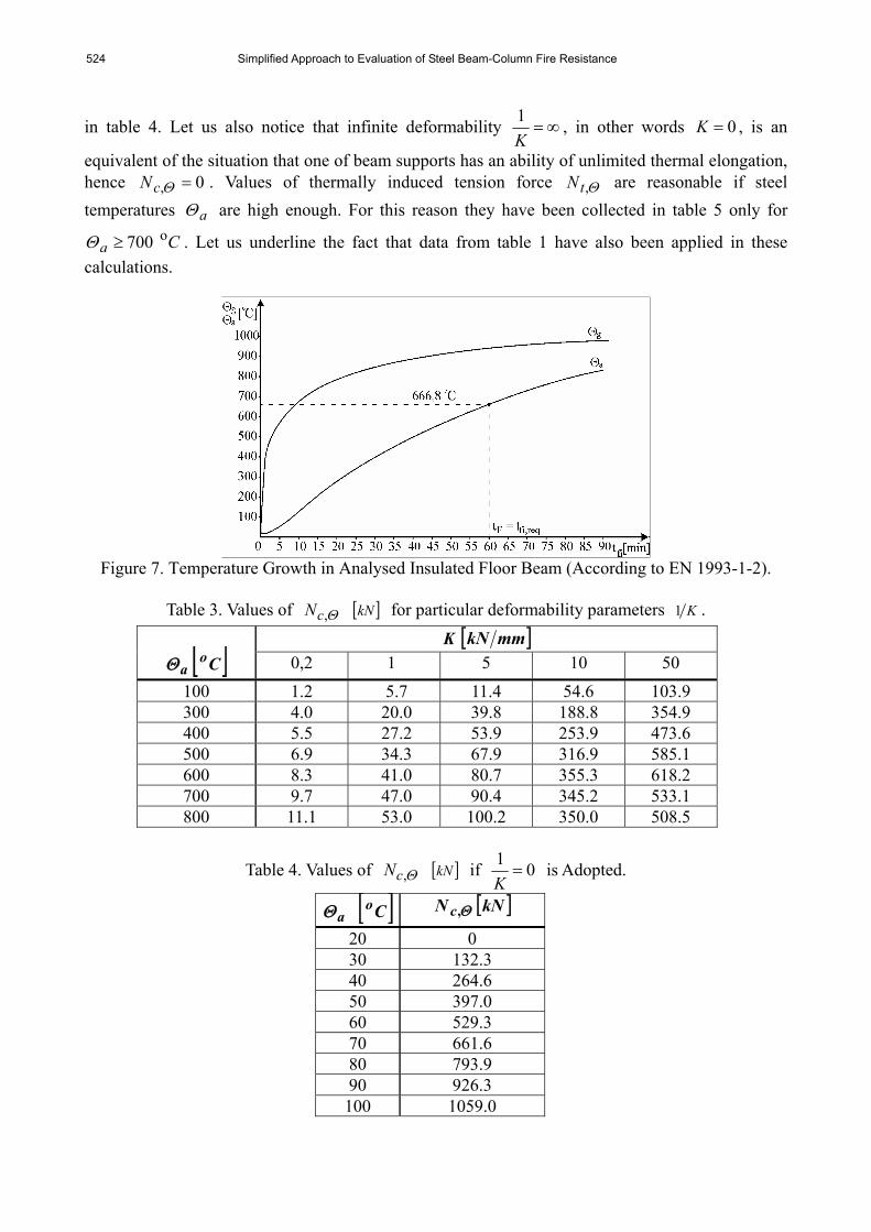
It is accepted that gas temperature gΘ increases in fire according to the standard fire curve.
Furthermore, uniform member steel temperature aΘ distribution is assumed, both across each beam cross-section and along the whole of its length. It means that the influence of more intensive top flange cooling process due to adjacent massive reinforced concrete floor slab is neglected. Values of aΘ in particular fire times fit have been determined applying EN 1993-1-2 approach.
Let us notice that after h 1, == reqfifi tt fire time period temperature aΘ reaches value
8,666 Co (fig. 7). The basic safety requirement reqfidfi tt ,, > leads to the conclusion that the analysed steel beam should loose the ability to carry applied loads in temperatures higher than this one. Values Θ,yk and Θ,Ek for particular aΘ have been adopted from table 1. Buckling instability
factor Θϕ has been calculated according to Eq. (14); moreover, value 0,1, =ΘϕL has been accepted. Finally, compression force Θ,cN values, taken from Eq. (26) for particular
deformability parameters K1 , are presented in table 3. In addition, values of Θ,cN if 01=
K
( ∞=K ) (in other words for fully restrained beam thermal elongation) have been separately shown
524 Simplified Approach to Evaluation of Steel Beam-Column Fire Resistance
in table 4. Let us also notice that infinite deformability ∞=K1 , in other words 0=K , is an
equivalent of the situation that one of beam supports has an ability of unlimited thermal elongation, hence 0, =ΘcN . Values of thermally induced tension force Θ,tN are reasonable if steel temperatures aΘ are high enough. For this reason they have been collected in table 5 only for
Cao 700≥Θ . Let us underline the fact that data from table 1 have also been applied in these
calculations.
Figure 7. Temperature Growth in Analysed Insulated Floor Beam (According to EN 1993-1-2).
Table 3. Values of Θ,cN [ ]kN for particular deformability parameters K1 .
K [ ]mmkN
aΘ [ ]Co 0,2 1 5 10 50 100 1.2 5.7 11.4 54.6 103.9 300 4.0 20.0 39.8 188.8 354.9 400 5.5 27.2 53.9 253.9 473.6 500 6.9 34.3 67.9 316.9 585.1 600 8.3 41.0 80.7 355.3 618.2 700 9.7 47.0 90.4 345.2 533.1 800 11.1 53.0 100.2 350.0 508.5
Table 4. Values of Θ,cN [ ]kN if 01=
K is Adopted.
aΘ [ ]Co Θ,cN [ ]kN
20 0 30 132.3 40 264.6 50 397.0 60 529.3 70 661.6 80 793.9 90 926.3 100 1059.0

M. Maślak 525
If the value of thermally activated force Θ,cN is known for given member temperature aΘ determination of specific safety levels is possible - Θρ ,1 from Eq. (1), similarly Θρ ,2 basing on Eq. (3) and Θρ ,3 according to Eq. (4). Moreover, value of Θρ ,4 can be identified if tension force Θ,tN is taken from Eq. (33). Study of particular dependences ( )aii Θρρ Θ =, obtained from such the calculations and shown in succeeding figures 8, 9, 10 and 11 enables the designer to evaluate one decisive value of beam fire resistance dfit , . It means the smallest aΘ value for
which the level ( ) 0,1=ai Θρ is reached.
Table 5. Values of Θ,tN [ ]kN for Particular Deformability Parameters K1 . K [ ]mmkN
aΘ [ ]Co 0,2 1 5 10 50
700 67,4 105,4 123,4 157,3 165,8 800 66,9 103,2 119,7 148,5 155,1
As it has been said before, in general the steel temperature increases together with fire development not only in analysed floor beam but also in columns bounding it. Then column flexural stiffness monotonically decreases. It means simultaneous growth of beam support deformability on horizontal displacement. For this reason real dependences ( )aii Θρρ Θ =, are more complicated than the ones shown in figures 8÷11, if such variability ( )aKK Θ11 = is taken into account. Nevertheless, for particular fire moment fit only one definite value of deformability K1 can always be reckoned. It allows to check all safety conditions Eq. (1), Eq. (3), Eq. (4) and Eq. (33) and, finally, to evaluate member fire resistance dfit , in a conventional manner, described above.
Figure 8. Fire resistance of Beam Analysed in the Example if Elastic-plastic Stability Condition
Eq. (1) is Taken Into Account.

526 Simplified Approach to Evaluation of Steel Beam-Column Fire Resistance
Figure 9. Fire Resistance of Beam Analysed in the Example, Received Basing on cNM −
Interaction Cross-section Load Bearing Capacity Limitation, Eq. (2).
Figure 10. Fire Resistance of the Same Beam Derived Owing to Elimination
of Ability of Weak Axis Buckling, Eq. (4).
M. Maślak 527
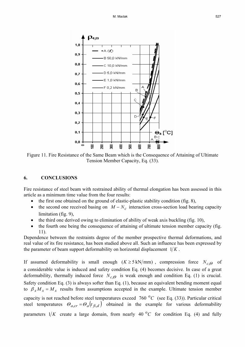
Figure 11. Fire Resistance of the Same Beam which is the Consequence of Attaining of Ultimate
Tension Member Capacity, Eq. (33). 6. CONCLUSIONS Fire resistance of steel beam with restrained ability of thermal elongation has been assessed in this article as a minimum time value from the four results:
• the first one obtained on the ground of elastic-plastic stability condition (fig. 8), • the second one received basing on cNM − interaction cross-section load bearing capacity
limitation (fig. 9), • the third one derived owing to elimination of ability of weak axis buckling (fig. 10), • the fourth one being the consequence of attaining of ultimate tension member capacity (fig.
11). Dependence between the restraints degree of the member prospective thermal deformations, and real value of its fire resistance, has been studied above all. Such an influence has been expressed by the parameter of beam support deformability on horizontal displacement K1 . If assumed deformability is small enough )5( mmkN ≥K , compression force Θ,cN of a considerable value is induced and safety condition Eq. (4) becomes decisive. In case of a great deformability, thermally induced force Θ,cN is weak enough and condition Eq. (1) is crucial. Safety condition Eq. (3) is always softer than Eq. (1), because an equivalent bending moment equal to xxx MM =β results from assumptions accepted in the example. Ultimate tension member
capacity is not reached before steel temperatures exceed Co 760 (see Eq. (33)). Particular critical steel temperatures ( )dfiacra t ,, ΘΘ = obtained in the example for various deformability
parameters K1 create a large domain, from nearly Co 40 for condition Eq. (4) and fully
528 Simplified Approach to Evaluation of Steel Beam-Column Fire Resistance
restrained beam elongation ( )∞=K (broken line A in fig. 10), to about Co 620 if condition Eq. (1) and infinite deformability ( )0=K are taken into account (broken line G in fig. 8). In conclusion, careful attention should be paid to the fact that such critical temperatures cra,Θ are
always significantly lower than ( ) Ct reqfiao 8,666, =Θ . It means that basic safety requirement
reqfidfi tt ,, > is not fulfilled. These results demonstrate that the designer’s belief that she/he will secure (without any additional structural analysis) safe and failure-free member working under fire conditions during at least required time reqfit , (in the above example one hour), if fire develops identically as the standard fire model, and fire protected insulation is chosen directly from producer specifications, is completely unjustified. In particular, beam protected in this way and analysed in the example could be buckled just after a few minutes of fire if flexural stiffness of columns bounding the beam is large enough. The catenary action of restrained steel beams comes into effect only when the beam deflection has been evidently developed. Consequently, the tension rupture failure mode of such beams takes place always behind the other failure domains (due to instability and yielding of cross-section). Considering the yielding of cross-section is not crucial for fire resistance evaluation of restrained steel beams, it is suggested that the global instability criterion should be used always if the beam deflection needs to be limited. On the other hand, the tension rupture criterion can be used only if such a deflection does not need to be limited. The study presented above shows absolute necessity to make separate thermal and structural analysis always if the parameters of fire protected insulation are chosen. Firstly, thermal field
( )fia tΘ in every member of load bearing structure should be obtained for particular fire scenario. Secondly, values of all thermally induced internal forces and moments, as well as the possible ways of their redistribution, should be calculated and discussed for given fire moments fit . Finally,
determination of critical temperature ( )dfiacra t ,, ΘΘ = which is a measure of member fire resistance is necessary, for instance in the simplified way presented in this article. Member fire resistance dfit , seems to be an appropriate measure giving the designer an opportunity to choose the parameters of fire insulation in optimal and easy way. Simply, its adopted kind will be satisfactory only if critical steel temperature cra,Θ is reached in each structural member later than
reqfit , occurs. In the presented example, the analysis of only one single member isolated from the whole of load bearing structure has been quite sufficient to reliably evaluate its fire resistance dfit , . However, in general complexity of possible interactions between all external as well as thermally induced actions leads to the conclusion that such a simple study can be insufficient. For this reason more complete research, basing on the analysis of the whole structure or at least its suitable substructure is recommended to perform always if possible. Finally, it is necessary to say that all results obtained on the ground of the methodology discussed in this paper can be interpreted only as an approximation of real values. In high temperatures, especially higher than Co 400 , creep of steel becomes considerably influential. A more precise analysis in which rheological effects are taken into account requires appropriate computer modelling.
M. Maślak 529
REFERENCES [1] Allam, A.M., Burgess, I.W. and Plank, R.J., “Performance-based Simplified Model for a
Steel Beam at Large Deflection in Fire”, Proceedings of 4th International Conference “Performance-based Codes and Fire Safety Design Methods”, 2002, Melbourne, Australia.
[2] Boissonnade, N., Jaspart, J-P., Muzeau, J-P. and Vilette, M., “New Interaction Formulae for Beam-columns in Eurocode 3: The French-Belgian Approach”, Proceedings of 3rd European Conference on Steel Structures “Eurosteel 2002”, September 19-20 2002, Coimbra, Portugal.
[3] Cai, J., Burgess, I.W. and Plank, R.J., “The Effect of Push-out of Perimeter Building Columns of Their Survival in Fire”, Proceedings of International Conference “Steel Structures of the 2000’s, 2002, Istanbul, Turkey.
[4] Huang, Z., Burgess, I.W. and Plank, R.J., “3D Modelling of Beam-columns with General Cross-sections in Fire”, Proceedings of 3rd International Workshop “Structures in Fire”, 2004, Ottawa, Canada.
[5] Liu, T.C.H., Fahad, M.K. and Davies, J.M., “Experimental Investigation of Behaviour of Axially Restrained Steel Beams in Fire”, Journal of Constructional Steel Research, 2002, Vol. 58.
[6] Lopes, N., Simões da Silva, L., Vila Real, P.M.M. and Piloto, P., “New Proposals for the Design of Steel Beam-columns in Case of Fire Including a New Approach for the Lateral-torsional Buckling, Computer and Structures, 2004, Vol. 82.
[7] Maślak, M., “Fire Resistance of Steel Beam-columns”, Proceedings of 11th International Conference on Metal Structures “Progress in Steel, Composite and Aluminium Structures, 2006, Rzeszów, Poland.
[8] Murzewski, J., “Columns and Beam-columns”, Proceedings of 2nd Regional Colloquium of Steel Structures, 1986, Budapest, Hungary.
[9] Murzewski, J., Gwóźdź, M., “Resistance of Steel Columns in Fire Temperatures”, Proceedings of 37th Scientific Conference, 1991, Krynica, Poland, Vol. 4.
[10] Muzeau, J-P., “Reliability of Steel Columns. Study of the Polish Standard Code”, Proceedings of 34th Scientific Conference, 1988, Krynica, Poland, Vol. 3.
[11] Valente, J.C., “Fire Resistance of Steel Columns with Elastically Restrained Axial Elongation and Bending”, Journal of Constructional Steel Research, 1999, Vol. 52.
[12] Vila Real, P.M.M., Lopes, N., Simões da Silva, L., Piloto, P. and Franssen, J-M., “Towards a Consistant Safety Format of Steel Beam-columns: Application of the New Interaction Formulae for Ambient Temperature to Elevated Temperatures”, Steel & Composite Structures, 2003, Vol. 3, No. 6.
[13] Vila Real, P.M.M., Lopes, N., Simões da Silva, L., Piloto, P. and Franssen, J-M., “Numerical Modelling of Steel Beam-columns in Case of Fire – Comparison with Eurocode 3, Fire Safety Journal, 2004, Vol. 39.
[14] Yin, Y.Z. and Wang, Y.C., “A Numerical Study of Large Deflection Behaviour of Restrained Steel Beams at Elevated Temperatures”, Journal of Constructional Steel Research, 2004, Vol. 60.
[15] DIN 18800, Stahlbauten, Bemessung und Konstruktion, Part 1 & 2. [16] EN 1993-1-2, Eurocode 3: Design of Steel Structures, Part 1-2: General Rules – Structural
Fire Design. [17] PN-90/B-03200, Steel Structures, Design rules.

![THE YAMABE FLOW arXiv:1803.07787v1 [math.DG] … · θ = −(Rθ −Rθ)θ for t ≥ 0, θ|t=0 = θ0, where R θ is the Webster scalar curvature of the contact form θ, and R θ is](https://img.pdfslide.net/doc/110x75/5ba147e809d3f2c06a8bf7e6/the-yamabe-flow-arxiv180307787v1-mathdg-r-r-for-t-.jpg)