Embed Size (px)
Citation preview
State departments of transportation are being requested to produce bridgedesigns that are cost-effective, require less maintenance over a projected75- to 100-year lifetime, and are adaptable to rapid construction opera-tions. Most continuous bridges in the United States constructed of pre-fabricated girders and high-quality materials meet these requirements.Some geographic areas, however, have steel beam girder bridges that areat a competitive disadvantage to precast, prestressed concrete in spans upto 150 ft. Tennessee is developing bridge systems for steel bridges that canbe erected similarly to precast, prestressed beams made continuous, withcranes of the same or lower lifting capacity, and can be fabricated at areduced cost to be competitively priced. This development, it is hoped, willlower prices for both concrete and steel bridges.
In 1995, the American Iron and Steel Institute (AISI) issued a set ofstandard rolled beam bridge designs, published as Short-Span SteelBridges (1). During the development of these standardized designs,the Tennessee Department of Transportation (TDOT) was asked toreview the draft versions. These standard designs served their statedpurposes: provide local agencies, which had no design staff, withpredesigned and detailed plans; provide efficient designs that couldcompete with standardized precast, prestressed simple-span concretebridges; and promote the use of rolled steel beam bridges in general.
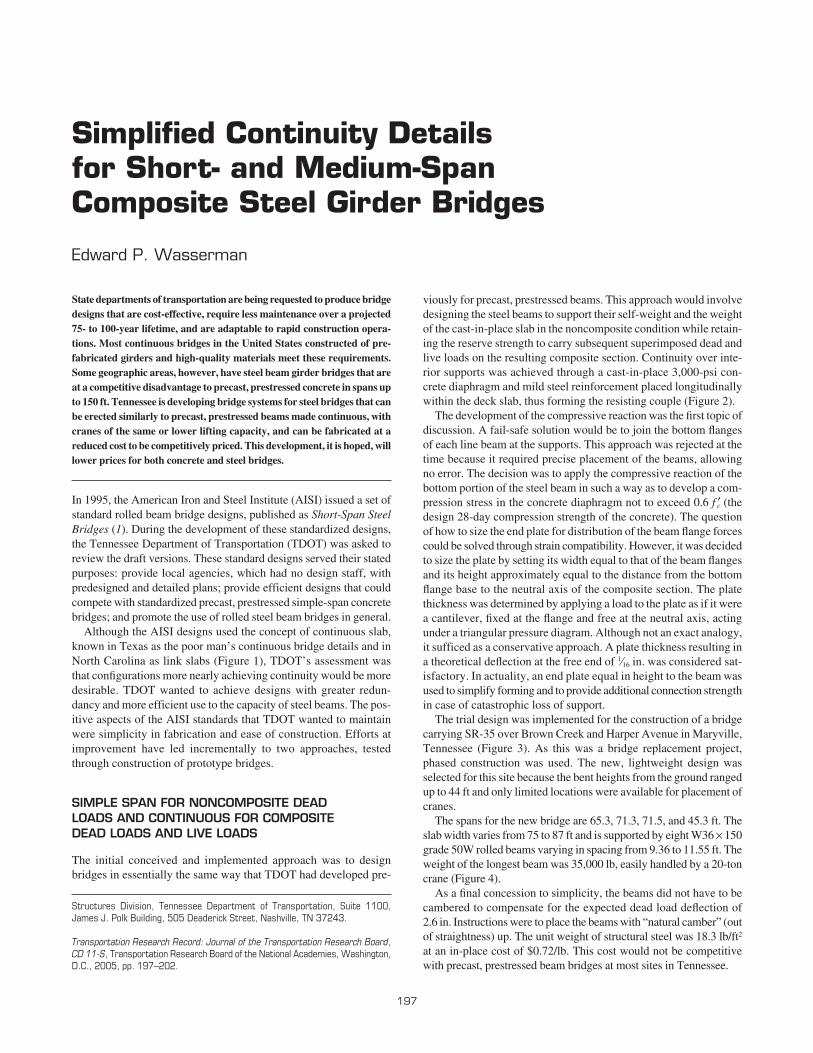
Although the AISI designs used the concept of continuous slab,known in Texas as the poor man’s continuous bridge details and inNorth Carolina as link slabs (Figure 1), TDOT’s assessment wasthat configurations more nearly achieving continuity would be moredesirable. TDOT wanted to achieve designs with greater redun-dancy and more efficient use to the capacity of steel beams. The pos-itive aspects of the AISI standards that TDOT wanted to maintainwere simplicity in fabrication and ease of construction. Efforts atimprovement have led incrementally to two approaches, testedthrough construction of prototype bridges.
SIMPLE SPAN FOR NONCOMPOSITE DEADLOADS AND CONTINUOUS FOR COMPOSITEDEAD LOADS AND LIVE LOADS
The initial conceived and implemented approach was to designbridges in essentially the same way that TDOT had developed pre-
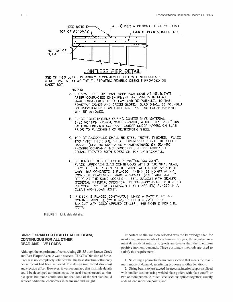
viously for precast, prestressed beams. This approach would involvedesigning the steel beams to support their self-weight and the weightof the cast-in-place slab in the noncomposite condition while retain-ing the reserve strength to carry subsequent superimposed dead andlive loads on the resulting composite section. Continuity over inte-rior supports was achieved through a cast-in-place 3,000-psi con-crete diaphragm and mild steel reinforcement placed longitudinallywithin the deck slab, thus forming the resisting couple (Figure 2).
The development of the compressive reaction was the first topic ofdiscussion. A fail-safe solution would be to join the bottom flangesof each line beam at the supports. This approach was rejected at thetime because it required precise placement of the beams, allowingno error. The decision was to apply the compressive reaction of thebottom portion of the steel beam in such a way as to develop a com-pression stress in the concrete diaphragm not to exceed 0.6 f ′c (thedesign 28-day compression strength of the concrete). The questionof how to size the end plate for distribution of the beam flange forcescould be solved through strain compatibility. However, it was decidedto size the plate by setting its width equal to that of the beam flangesand its height approximately equal to the distance from the bottomflange base to the neutral axis of the composite section. The platethickness was determined by applying a load to the plate as if it werea cantilever, fixed at the flange and free at the neutral axis, actingunder a triangular pressure diagram. Although not an exact analogy,it sufficed as a conservative approach. A plate thickness resulting ina theoretical deflection at the free end of 1⁄16 in. was considered sat-isfactory. In actuality, an end plate equal in height to the beam wasused to simplify forming and to provide additional connection strengthin case of catastrophic loss of support.
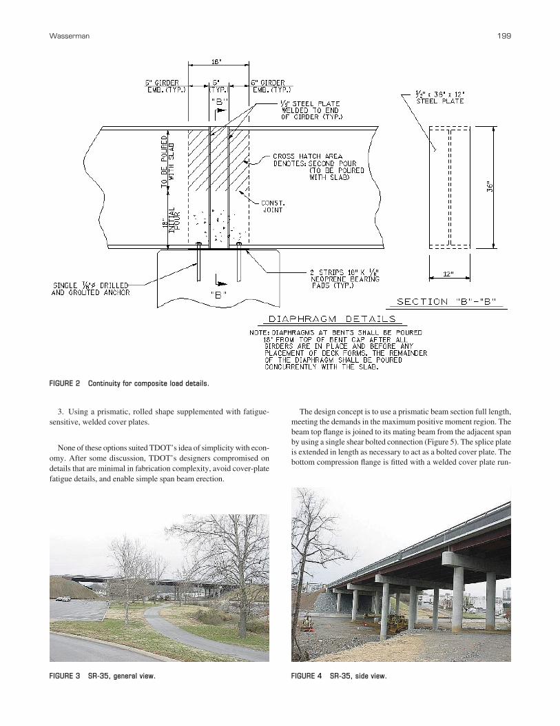
The trial design was implemented for the construction of a bridgecarrying SR-35 over Brown Creek and Harper Avenue in Maryville,Tennessee (Figure 3). As this was a bridge replacement project,phased construction was used. The new, lightweight design wasselected for this site because the bent heights from the ground rangedup to 44 ft and only limited locations were available for placement ofcranes.
The spans for the new bridge are 65.3, 71.3, 71.5, and 45.3 ft. Theslab width varies from 75 to 87 ft and is supported by eight W36 × 150grade 50W rolled beams varying in spacing from 9.36 to 11.55 ft. Theweight of the longest beam was 35,000 lb, easily handled by a 20-toncrane (Figure 4).
As a final concession to simplicity, the beams did not have to becambered to compensate for the expected dead load deflection of 2.6 in. Instructions were to place the beams with “natural camber” (outof straightness) up. The unit weight of structural steel was 18.3 lb/ft2
at an in-place cost of $0.72/lb. This cost would not be competitivewith precast, prestressed beam bridges at most sites in Tennessee.
Simplified Continuity Details for Short- and Medium-Span Composite Steel Girder Bridges
Edward P. Wasserman
Structures Division, Tennessee Department of Transportation, Suite 1100,James J. Polk Building, 505 Deaderick Street, Nashville, TN 37243.
197
Transportation Research Record: Journal of the Transportation Research Board,
CD 11-S, Transportation Research Board of the National Academies, Washington,D.C., 2005, pp. 197–202.
SIMPLE SPAN FOR DEAD LOAD OF BEAM,CONTINUOUS FOR ALL OTHER DEAD AND LIVE LOADS
Although the experiment of constructing SR-35 over Brown Creekand East Harper Avenue was a success, TDOT’s Division of Struc-tures was not completely satisfied that the best structural efficiencyper unit cost had been achieved. The design minimized shop costand erection effort. However, it was recognized that if simple detailscould be developed at modest cost, the steel beams erected as sim-ple spans but made continuous for dead load of the wet slab couldachieve additional economies in beam size and weight.
198 Transportation Research Record CD 11-S
Important to the solution selected was the knowledge that, formost span arrangements of continuous bridges, the negative mo-ment demands at interior supports are greater than the maximumpositive moment demands. Three customary methods are used tosatisfy this requirement:
1. Selecting a prismatic beam cross section that meets the maxi-mum moment demand, sacrificing economy at other locations;
2. Sizing beams to just exceed the needs at interior supports splicedwith smaller sections using welded plate girders with plate cutoffs ortwo or more prismatic, rolled-steel sections spliced together, usuallyat dead load inflection points; and
FIGURE 1 Link slab details.
3. Using a prismatic, rolled shape supplemented with fatigue-sensitive, welded cover plates.
None of these options suited TDOT’s idea of simplicity with econ-omy. After some discussion, TDOT’s designers compromised ondetails that are minimal in fabrication complexity, avoid cover-platefatigue details, and enable simple span beam erection.
Wasserman 199
The design concept is to use a prismatic beam section full length,meeting the demands in the maximum positive moment region. Thebeam top flange is joined to its mating beam from the adjacent spanby using a single shear bolted connection (Figure 5). The splice plateis extended in length as necessary to act as a bolted cover plate. Thebottom compression flange is fitted with a welded cover plate run-
FIGURE 2 Continuity for composite load details.
FIGURE 4 SR-35, side view.FIGURE 3 SR-35, general view.
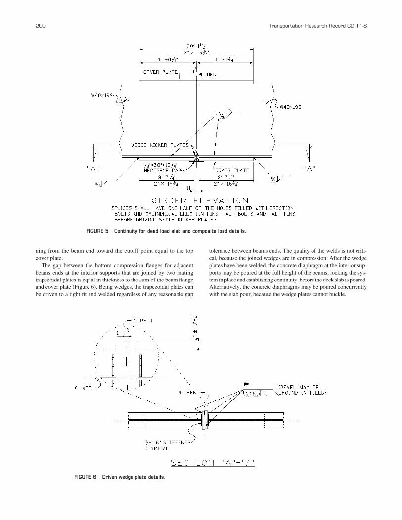
ning from the beam end toward the cutoff point equal to the topcover plate.
The gap between the bottom compression flanges for adjacentbeams ends at the interior supports that are joined by two matingtrapezoidal plates is equal in thickness to the sum of the beam flangeand cover plate (Figure 6). Being wedges, the trapezoidal plates canbe driven to a tight fit and welded regardless of any reasonable gap
200 Transportation Research Record CD 11-S
tolerance between beams ends. The quality of the welds is not criti-cal, because the joined wedges are in compression. After the wedgeplates have been welded, the concrete diaphragm at the interior sup-ports may be poured at the full height of the beams, locking the sys-tem in place and establishing continuity, before the deck slab is poured.Alternatively, the concrete diaphragms may be poured concurrentlywith the slab pour, because the wedge plates cannot buckle.
FIGURE 5 Continuity for dead load slab and composite load details.
FIGURE 6 Driven wedge plate details.

This concept was used to construct a two-span overpass replace-ment bridge at the DuPont Access Road over SR-1 in New John-sonville, Tennessee (Figure 7). The bridge has spans of 87 and76 ft and is 40 ft wide. Six W33 × 240 grade 50W rolled beamsspaced approximately 7 ft 5 in. on centers and supporting an 81⁄2-in.deck compose the superstructure. The unit weight of structuralsteel was 37.7 lb/ft2. Although the DuPont Access Road bridgemay appear to have less structural efficiency than the SR-35bridge, the two are comparable. The reason is that the end spanscontrolled both designs and the ratio of maximum positive momentsfor the DuPont Access Road to that of the SR-35 bridge is about1.57. The price of the steel from the low bidder was $0.56/lb inplace. Two other bids averaged $0.74/lb.
Significantly, the total bridge was constructed in 90 calendardays, without incentives, using the details.
EXPANDING THE RANGE OF APPLICABILITY
TDOT now has two other bridges under construction that increasethe limits on span length, using the simple span for dead load ofbeam, continuous for all other loads.
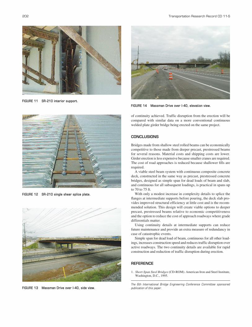
SR-210 over Pond Creek is an example of the upper limits of spanlength achievable with rolled-steel I-sections. The bridge is a five-span configuration with spans of 93.50, 103.25, 132.25, 132.25, and118.33 ft (Figure 8). The bridge is jointless, having integral abut-ments (Figures 9 and 10). These features reduce maintenance anddampen seismic motions.
The substructures are skewed 35° from the longitudinal axis. The42-ft-wide roadway is supported on five W40 × 248 ASTM A70950W rolled beams, spaced 8 ft 6 in. on centers. Figures 11 and 12show details of the continuity connections before the deck waspoured. The structural steel density was 34.48 lb/ft2. The beamswere set in 30 calendar days.
Massman Avenue over I-40 in Nashville (Figures 13 and 14) is anexperiment with welded plate girders erected as simple span for deadload girder and continuous for dead load of slab and all continuouscomposite loads. The 287-ft bridge has integral abutments and spansof 140 and 147 ft. Five 60-in. welded plate girders, spaced 9 ft 9 in.on centers, support a 46-ft roadway. The structural steel density is36.73 lb/ft2. This bridge will also be instrumented to verify the degree
Wasserman 201
FIGURE 7 DuPont Access Road, elevation view.
FIGURE 8 SR-210 under construction.
FIGURE 9 SR-210 integral abutment details.
FIGURE 10 SR-210 beam penetration details.
202 Transportation Research Record CD 11-S
of continuity achieved. Traffic disruption from the erection will becompared with similar data on a more conventional continuouswelded plate girder bridge being erected on the same project.
CONCLUSIONS
Bridges made from shallow steel rolled beams can be economicallycompetitive to those made from deeper precast, prestressed beamsfor several reasons. Material costs and shipping costs are lower.Girder erection is less expensive because smaller cranes are required.The cost of road approaches is reduced because shallower fills arerequired.
A viable steel beam system with continuous composite concretedeck, constructed in the same way as precast, prestressed concretebridges, designed as simple span for dead loads of beam and slab,and continuous for all subsequent loadings, is practical in spans upto 70 to 75 ft.
With only a modest increase in complexity details to splice theflanges at intermediate supports before pouring, the deck slab pro-vides improved structural efficiency at little cost and is the recom-mended solution. This design will create viable options to deeperprecast, prestressed beams relative to economic competitivenessand the option to reduce the cost of approach roadways where gradedifferentials matter.
Using continuity details at intermediate supports can reducefuture maintenance and provide an extra measure of redundancy incase of catastrophic events.
Simple span for dead load of beam, continuous for all other load-ings, increases construction speed and reduces traffic disruption overactive roadways. The two continuity details are available for rapidconstruction and reduction of traffic disruption during erection.
REFERENCE
1. Short-Span Steel Bridges (CD-ROM). American Iron and Steel Institute,Washington, D.C., 1995.
The 6th International Bridge Engineering Conference Committee sponsored
publication of this paper.
FIGURE 11 SR-210 interior support.
FIGURE 13 Massman Drive over I-40, side view.
FIGURE 14 Massman Drive over I-40, elevation view.
FIGURE 12 SR-210 single shear splice plate.