Embed Size (px)
Citation preview
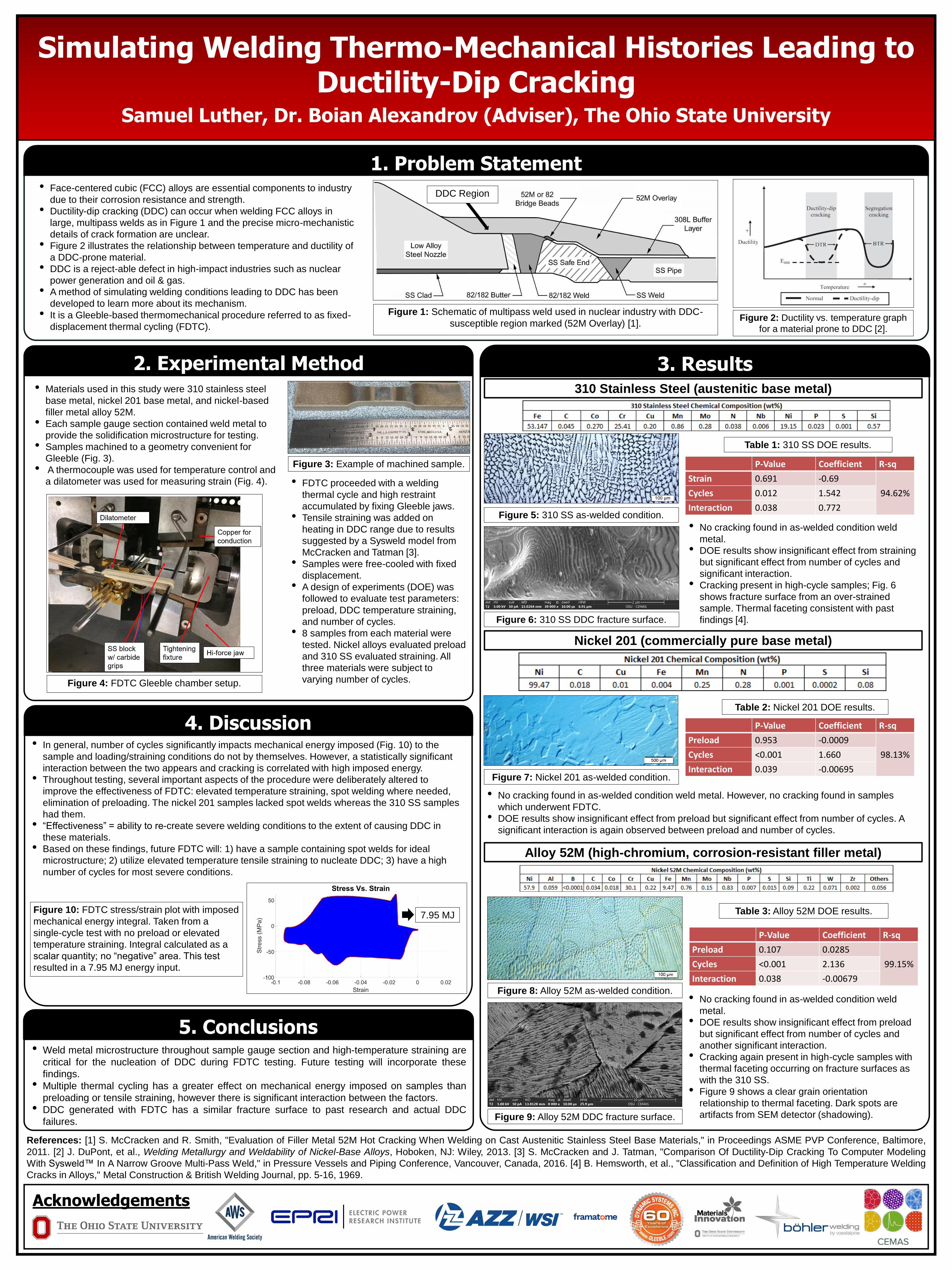
Simulating Welding Thermo-Mechanical Histories Leading to Ductility-Dip Cracking
Samuel Luther, Dr. Boian Alexandrov (Adviser), The Ohio State University
1. Problem Statement
3. Results
4. Discussion
5. Conclusions
2. Experimental Method
• Face-centered cubic (FCC) alloys are essential components to industry
due to their corrosion resistance and strength.
• Ductility-dip cracking (DDC) can occur when welding FCC alloys in
large, multipass welds as in Figure 1 and the precise micro-mechanistic
details of crack formation are unclear.
• Figure 2 illustrates the relationship between temperature and ductility of
a DDC-prone material.
• DDC is a reject-able defect in high-impact industries such as nuclear
power generation and oil & gas.
• A method of simulating welding conditions leading to DDC has been
developed to learn more about its mechanism.
• It is a Gleeble-based thermomechanical procedure referred to as fixed-
displacement thermal cycling (FDTC).
References: [1] S. McCracken and R. Smith, "Evaluation of Filler Metal 52M Hot Cracking When Welding on Cast Austenitic Stainless Steel Base Materials," in Proceedings ASME PVP Conference, Baltimore,
2011. [2] J. DuPont, et al., Welding Metallurgy and Weldability of Nickel-Base Alloys, Hoboken, NJ: Wiley, 2013. [3] S. McCracken and J. Tatman, "Comparison Of Ductility-Dip Cracking To Computer Modeling
With Sysweld™ In A Narrow Groove Multi-Pass Weld," in Pressure Vessels and Piping Conference, Vancouver, Canada, 2016. [4] B. Hemsworth, et al., "Classification and Definition of High Temperature Welding
Cracks in Alloys," Metal Construction & British Welding Journal, pp. 5-16, 1969.
• Weld metal microstructure throughout sample gauge section and high-temperature straining are
critical for the nucleation of DDC during FDTC testing. Future testing will incorporate these
findings.
• Multiple thermal cycling has a greater effect on mechanical energy imposed on samples than
preloading or tensile straining, however there is significant interaction between the factors.
• DDC generated with FDTC has a similar fracture surface to past research and actual DDC
failures.
Acknowledgements
Figure 2: Ductility vs. temperature graph
for a material prone to DDC [2].
Figure 4: FDTC Gleeble chamber setup.
Figure 1: Schematic of multipass weld used in nuclear industry with DDC-
susceptible region marked (52M Overlay) [1].
DDC Region
• Materials used in this study were 310 stainless steel
base metal, nickel 201 base metal, and nickel-based
filler metal alloy 52M.
• Each sample gauge section contained weld metal to
provide the solidification microstructure for testing.
• Samples machined to a geometry convenient for
Gleeble (Fig. 3).
• A thermocouple was used for temperature control and
a dilatometer was used for measuring strain (Fig. 4).
Figure 3: Example of machined sample.
310 Stainless Steel (austenitic base metal)
• FDTC proceeded with a welding
thermal cycle and high restraint
accumulated by fixing Gleeble jaws.
• Tensile straining was added on
heating in DDC range due to results
suggested by a Sysweld model from
McCracken and Tatman [3].
• Samples were free-cooled with fixed
displacement.
• A design of experiments (DOE) was
followed to evaluate test parameters:
preload, DDC temperature straining,
and number of cycles.
• 8 samples from each material were
tested. Nickel alloys evaluated preload
and 310 SS evaluated straining. All
three materials were subject to
varying number of cycles.
Nickel 201 (commercially pure base metal)
Alloy 52M (high-chromium, corrosion-resistant filler metal)
Figure 5: 310 SS as-welded condition.
Figure 6: 310 SS DDC fracture surface.
Table 1: 310 SS DOE results.
• No cracking found in as-welded condition weld
metal.
• DOE results show insignificant effect from straining
but significant effect from number of cycles and
significant interaction.
• Cracking present in high-cycle samples; Fig. 6
shows fracture surface from an over-strained
sample. Thermal faceting consistent with past
findings [4].
Table 2: Nickel 201 DOE results.
Figure 7: Nickel 201 as-welded condition.
• No cracking found in as-welded condition weld metal. However, no cracking found in samples
which underwent FDTC.
• DOE results show insignificant effect from preload but significant effect from number of cycles. A
significant interaction is again observed between preload and number of cycles.
Figure 8: Alloy 52M as-welded condition.
P-Value Coefficient R-sq
Preload 0.107 0.0285
99.15%Cycles <0.001 2.136
Interaction 0.038 -0.00679
Table 3: Alloy 52M DOE results.
Figure 9: Alloy 52M DDC fracture surface.
• No cracking found in as-welded condition weld
metal.
• DOE results show insignificant effect from preload
but significant effect from number of cycles and
another significant interaction.
• Cracking again present in high-cycle samples with
thermal faceting occurring on fracture surfaces as
with the 310 SS.
• Figure 9 shows a clear grain orientation
relationship to thermal faceting. Dark spots are
artifacts from SEM detector (shadowing).
• In general, number of cycles significantly impacts mechanical energy imposed (Fig. 10) to the
sample and loading/straining conditions do not by themselves. However, a statistically significant
interaction between the two appears and cracking is correlated with high imposed energy.
• Throughout testing, several important aspects of the procedure were deliberately altered to
improve the effectiveness of FDTC: elevated temperature straining, spot welding where needed,
elimination of preloading. The nickel 201 samples lacked spot welds whereas the 310 SS samples
had them.
• “Effectiveness” = ability to re-create severe welding conditions to the extent of causing DDC in
these materials.
• Based on these findings, future FDTC will: 1) have a sample containing spot welds for ideal
microstructure; 2) utilize elevated temperature tensile straining to nucleate DDC; 3) have a high
number of cycles for most severe conditions.
7.95 MJFigure 10: FDTC stress/strain plot with imposed
mechanical energy integral. Taken from a
single-cycle test with no preload or elevated
temperature straining. Integral calculated as a
scalar quantity; no “negative” area. This test
resulted in a 7.95 MJ energy input.
P-Value Coefficient R-sq
Preload 0.953 -0.0009
98.13%Cycles <0.001 1.660
Interaction 0.039 -0.00695
P-Value Coefficient R-sq
Strain 0.691 -0.69
94.62%Cycles 0.012 1.542
Interaction 0.038 0.772