Embed Size (px)
Citation preview

Automation of misaligned Simulation and Alignment
November 2019 Panda Collaboration Meeting, Darmstadt
Roman Klasen | [email protected]
1
Motivation
For software alignment studies, hundreds of simulation scenarios must be run.
Each scenario must include MC Data generation (100-500 concurrent jobs), Luminosity Fit (10-100
concurrent jobs), actual software alignment (3 Jobs) and result reprocessing.
They have to be in order, be sorted by misalignment case and magnitude, and each for multiple beam
momenta.
Calling each substep by hand is simply out of the question.
Im building upon Stefan Pflügers Luminosity Fit Framework
(https://github.com/panda-luminosity-detector-group/LuminosityFit), which calls performs simulations
and Luminosity Fit for a single run scenario, and expand it to easily execute hundreds of scenarios.
2
Reminder: Where to apply Misalignment
For misplaced Geometry:
- SimBox / SimDPM
- Digitization
- Reconstruction
Use this for realistic detector acceptances, but no
check for intersection components is available!
For misplaces Reconstructed Tracks:
- Reconstruction only, but use appropriate Flag
Use this is you need many different misaligned
scenarios, all can be done with a single MC data set.
Disadvantage: unrealistic detector acceptance.
3
Both use the same interface in FairRoot! Matrices are simple std::map<TString, TGeoHMatrix> and can be either streamed to root files or simple JSON files.
How does our Misalignment Model work?
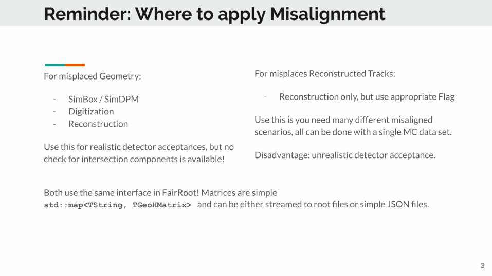
- Every component has a design position and a deviation from that design position
- Sub-components inherit this deviation, and have another deviation from their own design position
- Each box below represents a transformation matrix:
Note: intermediary matrices are optional / can be set to identity matrix! 4
cave_0 Main component M1*
Sub- component 1
Sub- component 2
M2_1*
M2_2*
etc.
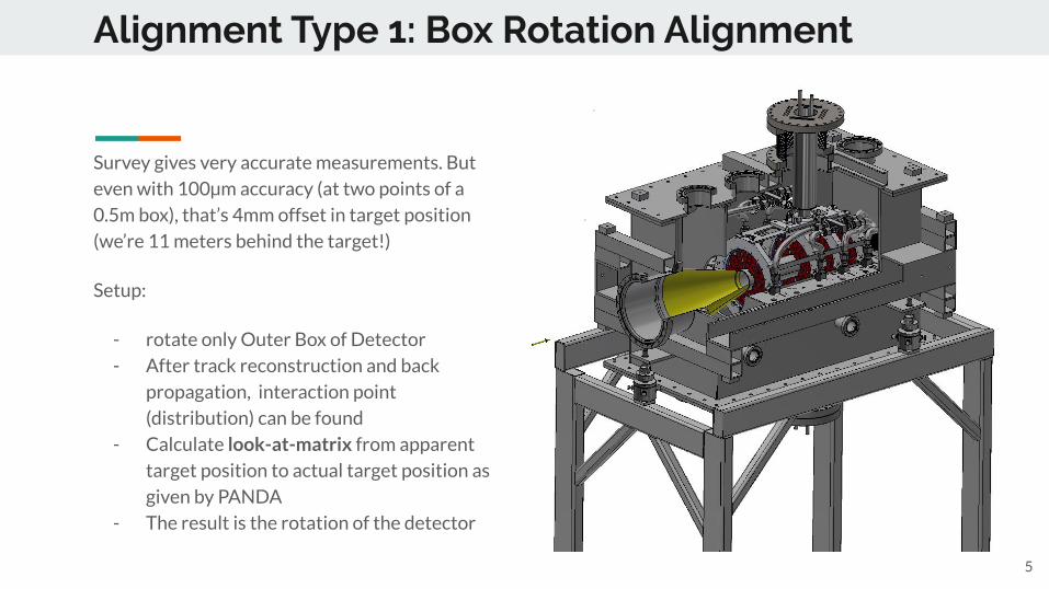
Alignment Type 1: Box Rotation Alignment
Survey gives very accurate measurements. But
even with 100µm accuracy (at two points of a
0.5m box), that’s 4mm offset in target position
(we’re 11 meters behind the target!)
Setup:
- rotate only Outer Box of Detector
- After track reconstruction and back
propagation, interaction point
(distribution) can be found
- Calculate look-at-matrix from apparent
target position to actual target position as
given by PANDA
- The result is the rotation of the detector
5
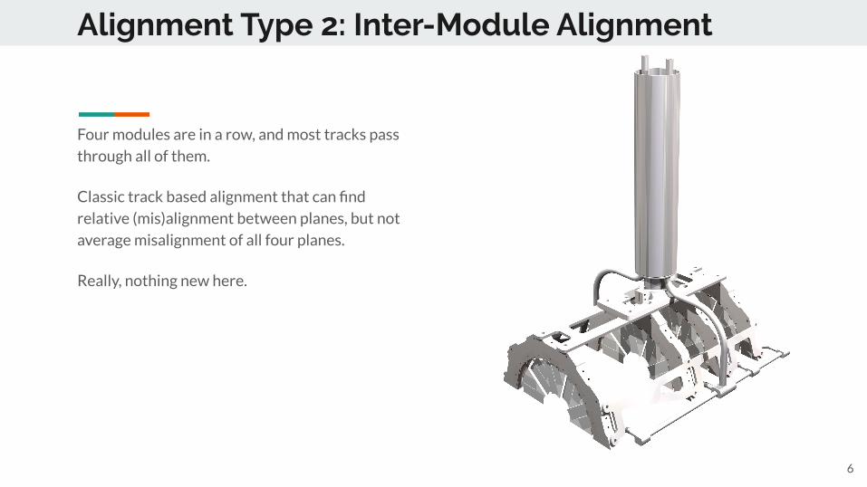
Alignment Type 2: Inter-Module Alignment
Four modules are in a row, and most tracks pass
through all of them.
Classic track based alignment that can find
relative (mis)alignment between planes, but not
average misalignment of all four planes.
Really, nothing new here.
6
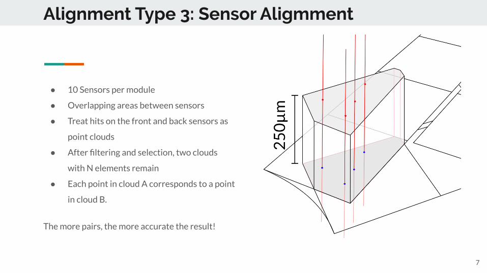
Alignment Type 3: Sensor Aligmment
7
● 10 Sensors per module
● Overlapping areas between sensors
● Treat hits on the front and back sensors as
point clouds
● After filtering and selection, two clouds
with N elements remain
● Each point in cloud A corresponds to a point
in cloud B.
The more pairs, the more accurate the result!
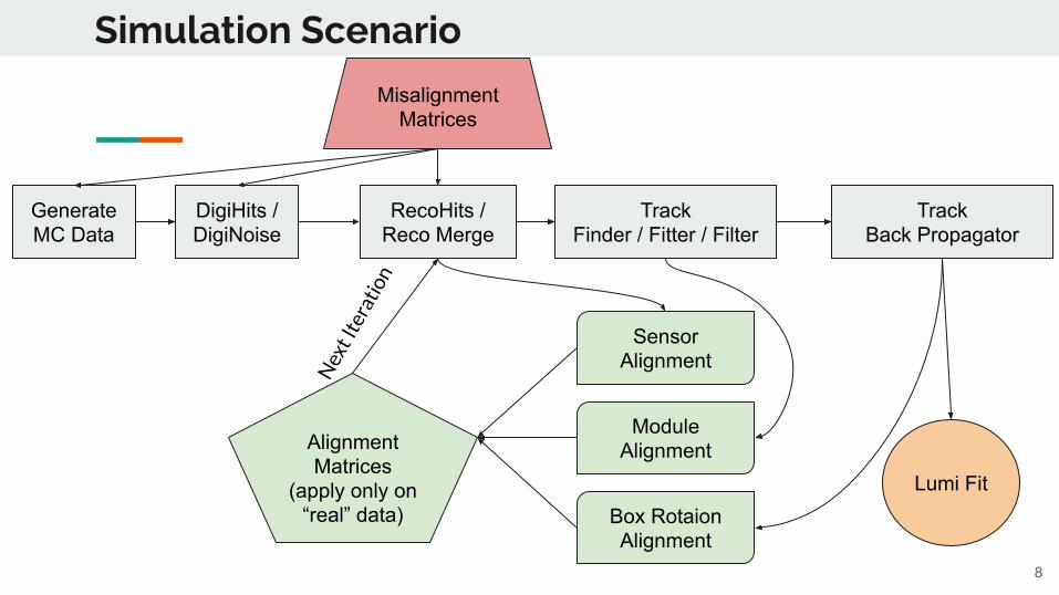
Simulation Scenario
8
GenerateMC Data
DigiHits /DigiNoise
RecoHits /Reco Merge
TrackFinder / Fitter / Filter
TrackBack Propagator
Box Rotaion Alignment
Module Alignment
Sensor Alignment
AlignmentMatrices
(apply only on “real” data)
Nex
t Ite
ratio
n
Misalignment Matrices
Lumi Fit
Automating Simulations
So obviously, this entire process is extremely tedious. We have multiple macros that perform the
PandaROOT simulations, several other scripts for the Luminosity Fit and then several more for the
alignment procedures.
It would be great, if we could somehow automate this process:
- Specify scenario in runConfigs (more later)
- Add scripts that create default runConfigs
- Use “Watchdogs” for running jobs
- Automate calls of Luminosity Fit Framework
- Automate Alignment (must be done after all jobs are complete)
- Run simulations again with new alignment matrices
- Fit Luminosity again
9
Specify a scenario in a runConfig!
RunConfig: Json files that have all infos for a scenario. They are the lingua franca for all alignment
modules. They contain:
- Beam Momentum
- Number of Jobs/Events per Job
- Files for misalignment matrices
- Which kind of alignment to do (some must be done sequentially!)
- Misalignment parameters, tailored to our detector
- Where to store alignment files
- Various housekeeping
The sequential part is very important, because alignment must happen from innermost components to
outermost. Misaligned Modules will give wrong target positions, so Box Rotation alignment is impossible
before Module alignment has happened. Same goes for Sensor Alignment.
In future versions, the runConfig will contain this sequential order as well, for now, only a single type of
misalignment is supported. 10
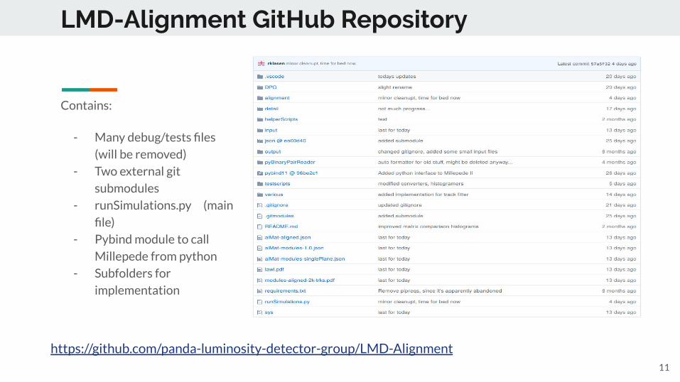
LMD-Alignment GitHub Repository
Contains:
- Many debug/tests files
(will be removed)
- Two external git
submodules
- runSimulations.py (main
file)
- Pybind module to call
Millepede from python
- Subfolders for
implementation
11
https://github.com/panda-luminosity-detector-group/LMD-Alignment
runSimulations.py
Main script that accepts command line flags and calls all submodules
- Create default runConfigs (json can be edited by Hand)
- Run Simulation Chain up to track fitter
- Run all alignment Scripts
- Run Luminosity Fit Framework
- Extract Luminosity from LumiFit result file
And most importantly, all of the above in a single call (just specify runConfig file):
- Run Simulations with specified misalignment matrices
- Get Luminosity
- Perform Alignment
- Run Simulations again with found alignment matrices
- Get new Luminosity
And even for a complete set of runConfig files. With a single command, 100s of scenarios can be run! 12
detail/ and alignment/
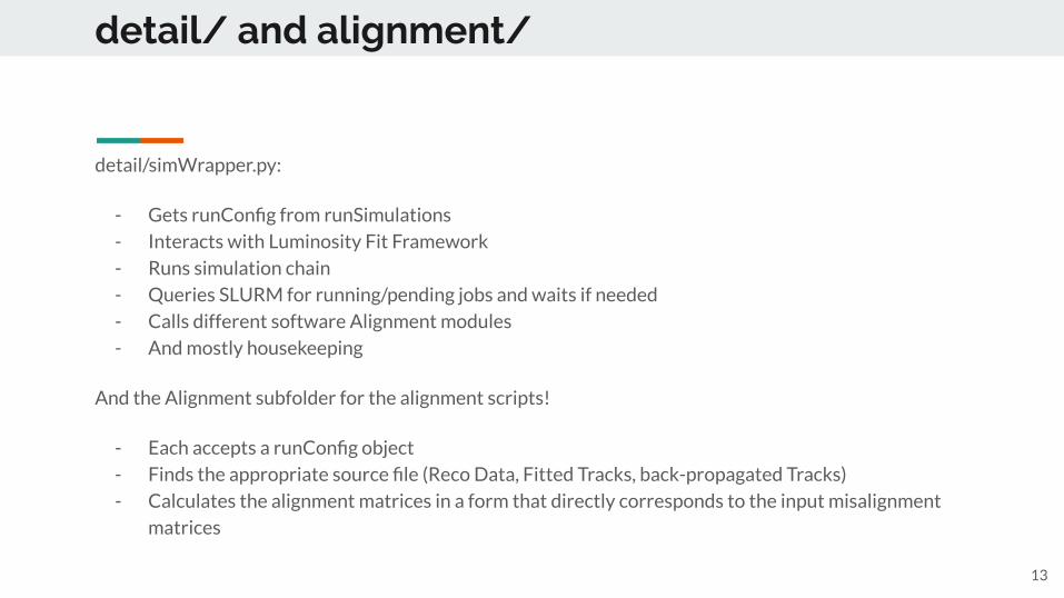
detail/simWrapper.py:
- Gets runConfig from runSimulations
- Interacts with Luminosity Fit Framework
- Runs simulation chain
- Queries SLURM for running/pending jobs and waits if needed
- Calls different software Alignment modules
- And mostly housekeeping
And the Alignment subfolder for the alignment scripts!
- Each accepts a runConfig object
- Finds the appropriate source file (Reco Data, Fitted Tracks, back-propagated Tracks)
- Calculates the alignment matrices in a form that directly corresponds to the input misalignment
matrices
13
Example: Job Watchdog code
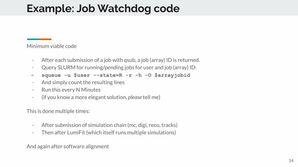
Minimum viable code
- After each submission of a job with qsub, a job (array) ID is returned.
- Query SLURM for running/pending jobs for user and job (array) ID:
- squeue -u $user --state=R -r -h -O $arrayjobid- And simply count the resulting lines
- Run this every N Minutes
- (if you know a more elegant solution, please tell me)
This is done multiple times:
- After submission of simulation chain (mc, digi, reco, tracks)
- Then after LumiFit (which itself runs multiple simulations)
And again after software alignment
14

Case study:Misaligned Geometries
- We study all three misalignment
scenarios.
- Apply misalignments of three degrees
for each misalignment type
- Determine Luminosity without
alignment
- Perform Software Alignment
- Compare found Matrices with actual
Matrices
- Apply alignment Matrices onto “real”
Data (=Reco Hits, re-merge, find tracks
again etc)
- Determine Luminosity again
- For multiple beam momenta
In total these are 11 run scenarios (9
misaligned, one aligned, one “misaligned” with
identityu matrices for cross-checks), each with
10+ sub steps -> 110+ individual commands
Extremely tedious without proper automation! 15
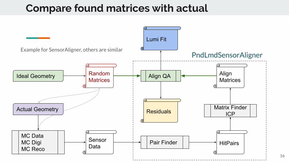
Compare found matrices with actual
16
Ideal Geometry
SensorData
AlignMatrices
RandomMatrices
Align QA
Pair Finder HitPairsMC DataMC DigiMC Reco
Matrix Finder ICP
PndLmdSensorAligner
ResidualsActual Geometry
Example for SensorAligner, others are similar
Lumi Fit
Optimizations for Box Rotation Alignment
17
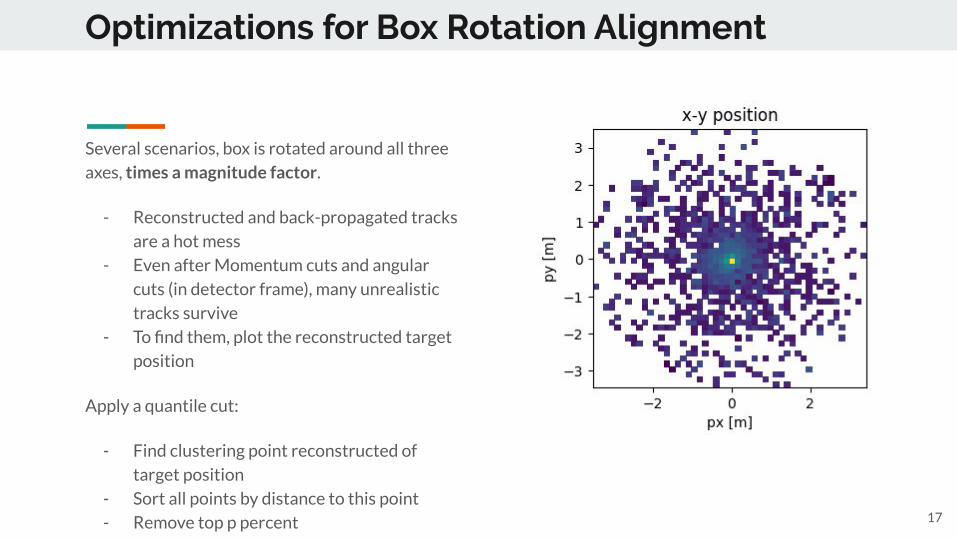
Several scenarios, box is rotated around all three
axes, times a magnitude factor.
- Reconstructed and back-propagated tracks
are a hot mess
- Even after Momentum cuts and angular
cuts (in detector frame), many unrealistic
tracks survive
- To find them, plot the reconstructed target
position
Apply a quantile cut:
- Find clustering point reconstructed of
target position
- Sort all points by distance to this point
- Remove top p percent
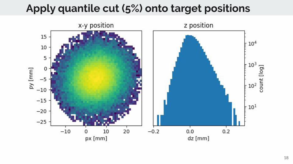
Apply quantile cut (5%) onto target positions
18
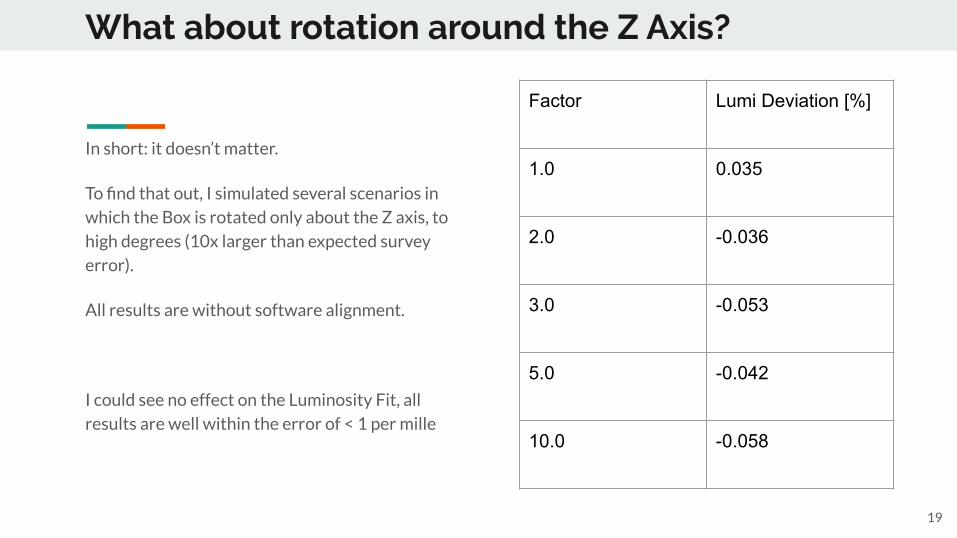
What about rotation around the Z Axis?
In short: it doesn’t matter.
To find that out, I simulated several scenarios in
which the Box is rotated only about the Z axis, to
high degrees (10x larger than expected survey
error).
All results are without software alignment.
I could see no effect on the Luminosity Fit, all
results are well within the error of < 1 per mille
19
Factor Lumi Deviation [%]
1.0 0.035
2.0 -0.036
3.0 -0.053
5.0 -0.042
10.0 -0.058
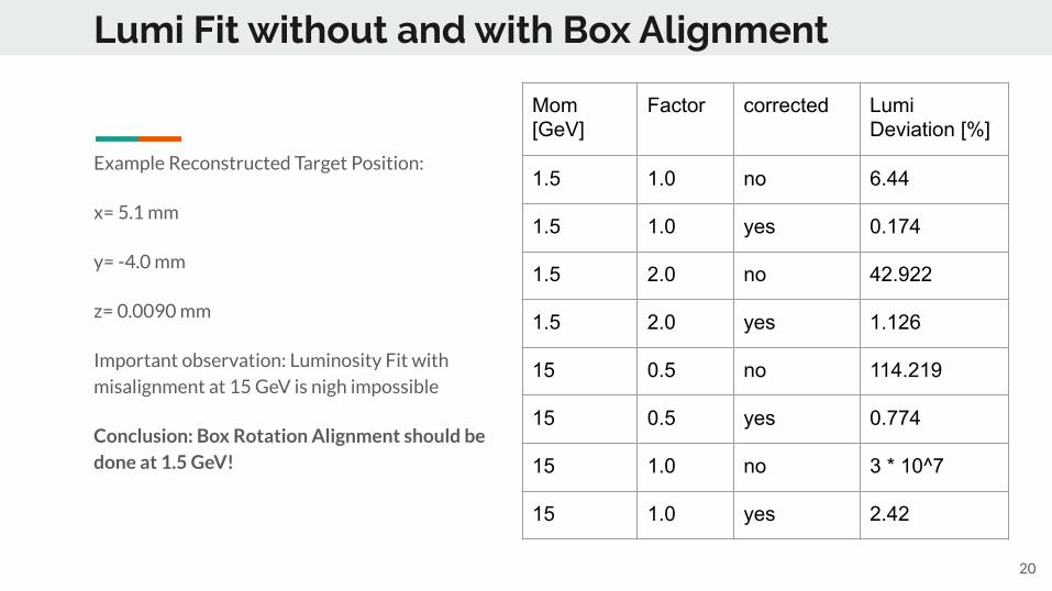
Lumi Fit without and with Box Alignment
20
Example Reconstructed Target Position:
x= 5.1 mm
y= -4.0 mm
z= 0.0090 mm
Important observation: Luminosity Fit with
misalignment at 15 GeV is nigh impossible
Conclusion: Box Rotation Alignment should be done at 1.5 GeV!
Mom [GeV]
Factor corrected Lumi Deviation [%]
1.5 1.0 no 6.44
1.5 1.0 yes 0.174
1.5 2.0 no 42.922
1.5 2.0 yes 1.126
15 0.5 no 114.219
15 0.5 yes 0.774
15 1.0 no 3 * 10^7
15 1.0 yes 2.42
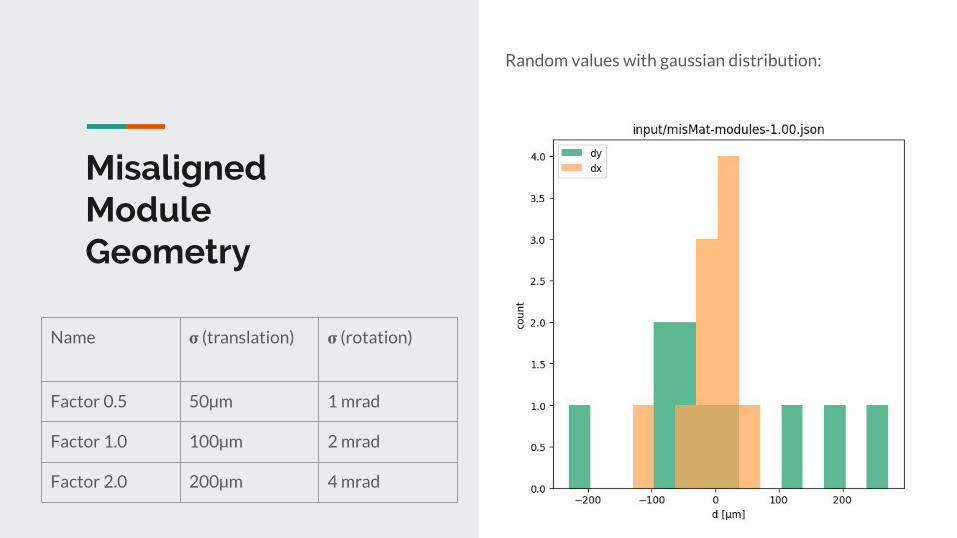
Misaligned ModuleGeometry
21
Random values with gaussian distribution:
Name 𝛔 (translation) 𝛔 (rotation)
Factor 0.5 50µm 1 mrad
Factor 1.0 100µm 2 mrad
Factor 2.0 200µm 4 mrad
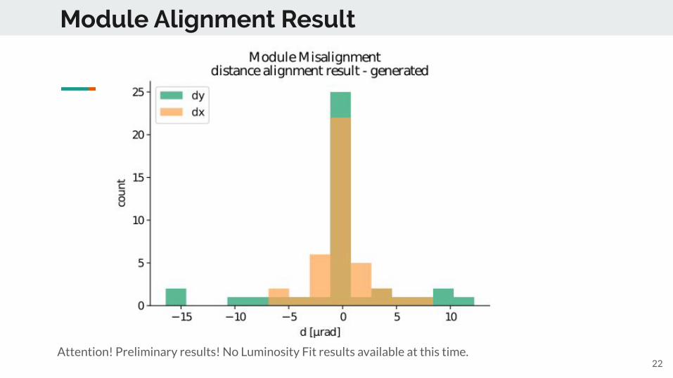
Module Alignment Result
22Attention! Preliminary results! No Luminosity Fit results available at this time.
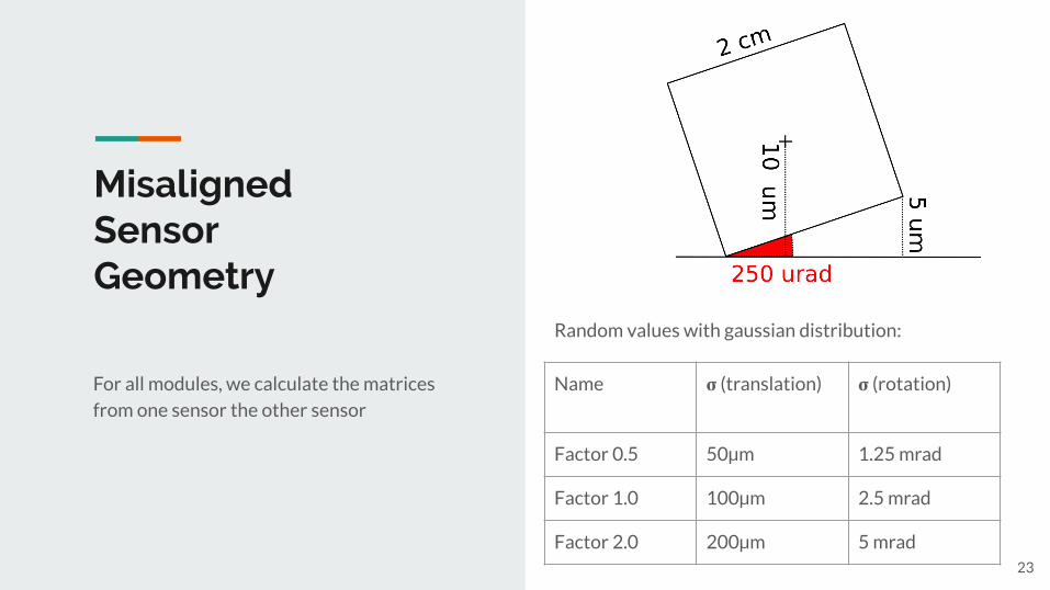
Misaligned SensorGeometry
For all modules, we calculate the matrices
from one sensor the other sensor
23
Random values with gaussian distribution:
Name 𝛔 (translation) 𝛔 (rotation)
Factor 0.5 50µm 1.25 mrad
Factor 1.0 100µm 2.5 mrad
Factor 2.0 200µm 5 mrad
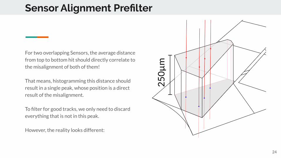
Sensor Alignment Prefilter
24
For two overlapping Sensors, the average distance
from top to bottom hit should directly correlate to
the misalignment of both of them!
That means, histogramming this distance should
result in a single peak, whose position is a direct
result of the misalignment.
To filter for good tracks, we only need to discard
everything that is not in this peak.
However, the reality looks different:
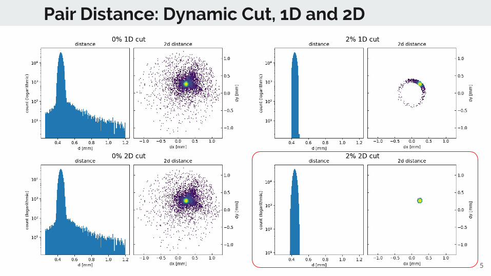
Pair Distance: Dynamic Cut, 1D and 2D
25
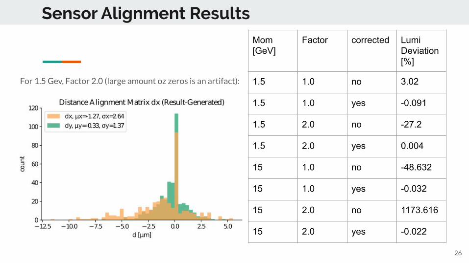
Sensor Alignment Results
26
Mom [GeV]
Factor corrected Lumi Deviation [%]
1.5 1.0 no 3.02
1.5 1.0 yes -0.091
1.5 2.0 no -27.2
1.5 2.0 yes 0.004
15 1.0 no -48.632
15 1.0 yes -0.032
15 2.0 no 1173.616
15 2.0 yes -0.022
For 1.5 Gev, Factor 2.0 (large amount oz zeros is an artifact):
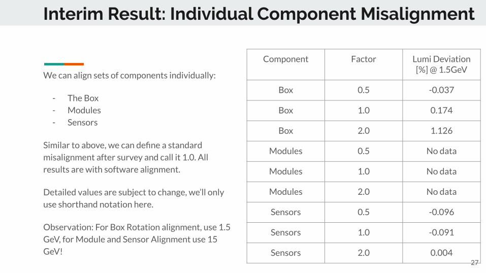
Interim Result: Individual Component Misalignment
We can align sets of components individually:
- The Box
- Modules
- Sensors
Similar to above, we can define a standard
misalignment after survey and call it 1.0. All
results are with software alignment.
Detailed values are subject to change, we’ll only
use shorthand notation here.
Observation: For Box Rotation alignment, use 1.5
GeV, for Module and Sensor Alignment use 15
GeV!
Component Factor Lumi Deviation [%] @ 1.5GeV
Box 0.5 -0.037
Box 1.0 0.174
Box 2.0 1.126
Modules 0.5 No data
Modules 1.0 No data
Modules 2.0 No data
Sensors 0.5 -0.096
Sensors 1.0 -0.091
Sensors 2.0 0.00427
Conclusion
- Software alignment is still work-in-progress
- Luminosity determination with misaligned geometry is difficult
- Determined Alignment Matrices drastically improve LumiFit Quality!
Roadmap:
- Mixing of misalignments- Modularization for different experiments
28

Thank you for your attention!
29