Embed Size (px)
Citation preview

ISIJ International, Vol. 55 (2015), No. 8
© 2015 ISIJ1633
ISIJ International, Vol. 55 (2015), No. 8, pp. 1633–1641
* Corresponding author: E-mail: [email protected]: http://dx.doi.org/10.2355/isijinternational.ISIJINT-2014-791
1. Introduction
Phosphorus is known as embrittlement prone during heat treatment and to decrease the ductility of steel. For petro-leum pipeline, cryogenic vessel, marine and automobile exterior,1,2) lowering phosphorus content in steel is a critical requirement. Dephosphorization is an optional oxidation process of phosphorus and carbon. Considering the ther-modynamic condition of the dephosphorization reaction,3–5) the temperature of molten bath should be low and carbon–oxygen reaction should be restrained.
The key to dephosphorization operation is to attain P con-tents as close to equilibrium as possible and strengthen the stirring effects of dephosphorization. Many researchers3–7) had reported previous works on removing phosphorus from liquid iron and there were several methods8–12) to remove phosphorus to produce low phosphorus steel. In particular, Healy,3) in 1970, published the formula (Eq. (1)) very often referred to the calculation of equilibrium phosphorus parti-tion ratio involving phosphorus partition ratio, lime, and iron contents in slag and temperature.
Simulation and Application of Top Lance with Various Tilt Angles in Dephosphorization Ladle Furnace
Fuhai LIU,1,2) Rong ZHU,1,2)* Qigang WANG2) and Ruiguo BAI3)
1) Beijing Key Laboratory of Research Center of Special Melting and Preparation of High-end Metal Materials, University of Science and Technology Beijing, No. 30, Xueyuan Road, Haidian District, Beijing, 100083 China. 2) School of Metallurgi-cal and Ecological Engineering, University of Science and Technology Beijing, No. 30, Xueyuan Road, Haidian District, Beijing, 100083 China. 3) Chengde Iron and Steel Company, Chengde Iron and Steel Company, No. 1, Binguan Road, Shuan-gluan District, Chengde, Hebei, 067002 China.
(Received on December 15, 2014; accepted on April 2, 2015)
Characteristics of flow field and stirring effects of top lance with various tilt angles (Tilt angles were 39°, 41°, 43°, 45° and 47°, respectively) on the molten bath were studied. The mixing time, impacting depth and impacting diameter were measured by water experiment. Flow field characteristics of three-phase flow were simulated by Fluent software. It was found that 43° oxygen lance could get the shortest mixing time being 56 s, the medium impacting depth being 36 mm and medium impacting diameter being 115 mm. When injecting by the 43° oxygen lance, average flow velocity of molten bath was the biggest being 0.0329 m/s, and volume of dead-zone was the minimum being 1.90 m3. In order to study metallurgi-cal effects of oxygen lance with tilt angle, both 43° and 45° oxygen lances were experimented in a dephos-phorization ladle furnace. The experiment showed that the oxygen lance with tilt angle can guarantee the normal smelting process. Compared with the 45° oxygen lance, the content of phosphorus in semi-steel B was decreased by 0.012 mass%, the dephosphorization rate was increased by 7.9% and the content of T. Fe loss was dropped by 1.9 mass%. It proved the oxygen lance with tilt angle could get a remarkable dephosphorization effect in a ladle furnace.
KEY WORDS: ladle furnace; top-blowing; water experiment; numerical simulation.
log
(mass%P)
[mass%P]. (mass%CaO)
. log(mass%T. Fe
= +
+
22 3500 08
2 5
T
))−16 ...... (1)
Mukawa and Mizukami6) concluded that if stirring energy (ε) and the rate of oxygen supply (V) simultane-ous increased, it was a effective measure to promote the dephosphorization reaction, when ε=1.51 V2+3.31 V. K. Yoshida and I. Yamazaki et al.9) analyzed the effect of SRP (Simple Refining Process) technology on improving the mass production process of low-phosphorus, which had been developed at Kashima steel works. M. Ina11) reported that injecting CaO powder by bottom-nozzle in BOF could improve stirring effect and increase the dephosphorization rate, and the method was called LD-ORP (LD converter–Optimized Refining Process).
From the literature reviews,3–12) the following aspects could be taken for granted: In dephosphorization process, both CaO and FeO were important components in slag. The amount of CaO was determined so as the CaO/SiO2 weight ratio of slag to attain appropriate basicity. Lowering smelt-ing temperature and improving stirring effect increased the dephosphorization rate.
Chengde iron and steel company prohibited CaO addi-tion in converter vanadium extraction process, since CaO addition decreased the level of vanadium content in slag
ISIJ International, Vol. 55 (2015), No. 8
© 2015 ISIJ 1634
leading to disadvantages for economic recovery. Without CaO addition, P2O5 could not form tri-calcium phosphate (3CaO·P2O5) in slag, and returned into the molten bath. In order to attain P contents as close to equilibrium as pos-sible and strengthen the effects of vanadium extraction and dephosphorization, the MURC (Multi-Refining Converter) operation was carried out in Chengde iron and steel com-pany. In this operation, one converter was used to obtain high level of vanadium content in slag, and the other one was used to smelt high phosphorus semi-steel. However, the phosphorus content in molten steel was still in the range of 0.025 mass% to 0.031 mass%.
For further decreasing the content of phosphorus in mol-ten steel, the top lance with tilt angle was used in a ladle furnace. Since, the silicon content was quite low in the range of 0.003 mass% to 0.005 mass% and the temperature of semi-steel <1 320°C, that seemed a suitable thermodynamic condition for dephosphorization, even though the range of phosphorus content in semi-steel was from 0.136 mass% to 0.143 mass% after vanadium extraction.
In this paper, characteristics of flow field and stirring effects of five kinds of tilt angles were analyzed. Mixing time, impacting depth and impacting diameter were mea-sured by water experiment. The flow field characteristics of three-phase flow were researched by numerical simulation. The oxygen lance with tilt angle was used to dephosphori-zation in a 100 t ladle furnace to study dephosphorization rate and T. Fe content in slag. It lays a foundation on the application of oxygen lance with tilt angle in a ladle furnace and on the improvement of dephosphorization rate.
2. Water Model Experiment
2.1. Experimental PrincipleThe stirring force, which was generated by carbon oxygen
reaction in dephosphorization process, was small. Therefore, it was a scientific and effective way to study stirring energy in a ladle furnace dephosphorization process by water exper-iment. Based on the similarity of kinetics and geometry,13–15) a physical model was developed. The top lance with tilt angle was used in the physical model. Taking inertial force and gravity into account (Eq. (2)), the modified Froude16) number was used to calculate similar principle numbers.
Fr Fru
gd
u
gdg
l g
g
l g
’ ’ ,= ×−
= ×−
1
212
1
1
1 1
that isρ
ρ ρρ
ρ ρ .... (2)
The conversion can get Eq. (3):
Q
Q
d
d
M
l g
l g
g
g
l g
l g
g
g
1 1
5
1 1
1
5
1 1
1
=
×
−−
×
= ×−−
×
ρ ρρ ρ
ρρ
ρ ρρ ρ
ρρ
.................. (3)
where, M was similarity ratio of the model; u, u1 were gas velocities of the model and the prototype (m·s −1); Q, Q1 presented gas flows of the model and the prototype (m3·h −1); d, d1 standed for nozzle diameters of the model and the pro-totype (mm); ρl, ρl1 were liquid density of the model and the prototype (kg·m −3); ρg, ρg1 presented gas density of the model and the prototype (kg·m −3); g acted as acceleration
of gravity (m·s −2); the subscripts l, g were short for liquid and gas. The prototype and model parameters were shown in Table 1.
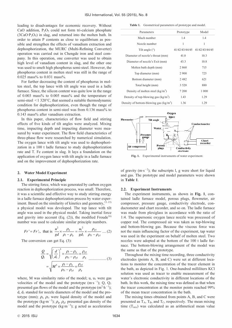
2.2. Experiment InstrumentsThe experiment instruments, as shown in Fig. 1, con-
tained ladle furnace model, porous plugs, flowmeter, air compressor, pressure gauge, conductivity electrode, con-ductometer and chart recorder, and so on. The ladle furnace was made from plexiglass in accordance with the ratio of 1:4. The supersonic oxygen lance nozzle was processed of copper rod. The compressed air was taken as top-blowing and bottom-blowing gas. Because the viscous force was not the main influencing factor of the experiment, tap water was used in the experiment on behalf of molten steel. Two nozzles were adopted at the bottom of the 100 t ladle fur-nace. The bottom-blowing arrangement of the model was the same as that of the prototype.
Throughout the mixing time recording, three conductivity electrodes (points A, B, and C) were set at different loca-tions to monitor the concentration of the tracer element in the bath, as depicted in Fig. 1. One-hundred milliliters KCl solution was used as tracer to enable measurement of the water’s electronic conductivity in different locations of the bath. In this work, the mixing time was defined as that when the tracer concentration at the monitor points reached 99% of the mean tracer concentration in the bath.
The mixing times obtained from points A, B, and C were presented as TA, TB, and TC, respectively. The mean mixing time (Tmix) was calculated as an arithmetical mean value
Table 1. Geometrical parameters of prototype and model.
Parameters Prototype Model
Mach number 1.4 1.4
Nozzle number 1 1
Tilt angle (°) 41/42/43/44/45 41/42/43/44/45
Diameter of nozzle’s throat (mm) 41.0 10.3
Diameter of nozzle’s Exit (mm) 43.3 10.8
Molten bath depth (mm) 2 860 715
Top diameter (mm) 2 900 725
Bottom diameter (mm) 2 482 621
Total height (mm) 3 520 880
Density of molten steel (kg/m3) 7 200 1 000
Density of top-blowing gas (kg/m3) 1.43 1.29
Density of bottom-blowing gas (kg/m3) 1.36 1.29
Fig. 1. Experimental instruments of water experiment.
ISIJ International, Vol. 55 (2015), No. 8
© 2015 ISIJ1635
using Eq. (4):
TT T T
MA B C=+ +3
........................... (4)
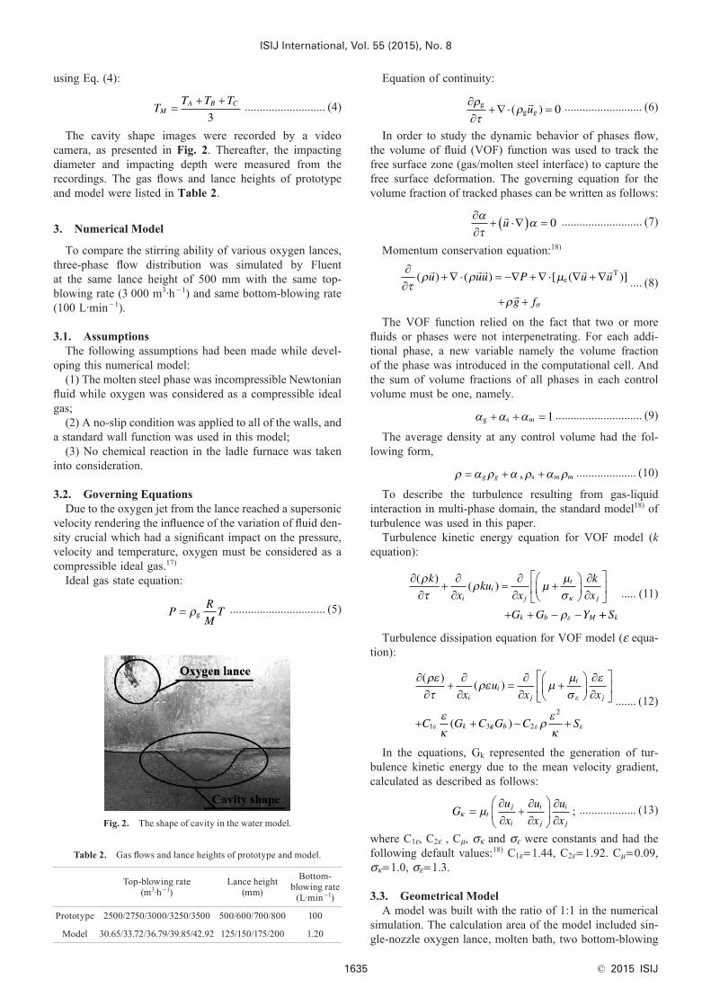
The cavity shape images were recorded by a video camera, as presented in Fig. 2. Thereafter, the impacting diameter and impacting depth were measured from the recordings. The gas flows and lance heights of prototype and model were listed in Table 2.
3. Numerical Model
To compare the stirring ability of various oxygen lances, three-phase flow distribution was simulated by Fluent at the same lance height of 500 mm with the same top-blowing rate (3 000 m3·h −1) and same bottom-blowing rate (100 L·min −1).
3.1. AssumptionsThe following assumptions had been made while devel-
oping this numerical model:(1) The molten steel phase was incompressible Newtonian
fluid while oxygen was considered as a compressible ideal gas;
(2) A no-slip condition was applied to all of the walls, and a standard wall function was used in this model;
(3) No chemical reaction in the ladle furnace was taken into consideration.
3.2. Governing EquationsDue to the oxygen jet from the lance reached a supersonic
velocity rendering the influence of the variation of fluid den-sity crucial which had a significant impact on the pressure, velocity and temperature, oxygen must be considered as a compressible ideal gas.17)
Ideal gas state equation:
PR
MT= ρg ................................ (5)
Equation of continuity:
∂∂
+∇ ⋅ =ρτ
ρgg( )
ug 0 .......................... (6)
In order to study the dynamic behavior of phases flow, the volume of fluid (VOF) function was used to track the free surface zone (gas/molten steel interface) to capture the free surface deformation. The governing equation for the volume fraction of tracked phases can be written as follows:
∂∂
+ ⋅∇( ) =ατ
α
u 0 ........................... (7)
Momentum conservation equation:18)
∂∂
+∇ ⋅ = −∇ +∇ ⋅ ∇ +∇
+ +τρ ρ µ
ρ
( ) ( ) [ ( )]
u uu u uP
g f
eT
σ
.... (8)
The VOF function relied on the fact that two or more fluids or phases were not interpenetrating. For each addi-tional phase, a new variable namely the volume fraction of the phase was introduced in the computational cell. And the sum of volume fractions of all phases in each control volume must be one, namely.
α α αg + + =s m 1 ............................. (9)
The average density at any control volume had the fol-lowing form,
ρ α ρ α ρ α ρ= + +g g m ms s .................... (10)
To describe the turbulence resulting from gas-liquid interaction in multi-phase domain, the standard model18) of turbulence was used in this paper.
Turbulence kinetic energy equation for VOF model (k equation):
∂∂
+∂∂
=∂∂
+
∂∂
+ + − −
( )( )
ρτ
ρ µµσ
ρκ
ε
k
xku
x
k
x
G G Y
ii
j
t
j
k b M ++ Sk
..... (11)
Turbulence dissipation equation for VOF model (ε equa-tion):
∂∂
+∂∂
=∂∂
+
∂∂
+ +
( )( )
(
ρετ
ρε µµσ
ε
εκ
ε
ε
xu
x x
C G C
ii
j
t
j
k1 3εε ε ερεκ
G C Sb )− +2
2....... (12)
In the equations, Gk represented the generation of tur-bulence kinetic energy due to the mean velocity gradient, calculated as described as follows:
Gu
x
u
x
u
xt
j
i
i
j
i
jκ µ=
∂∂
+∂∂
∂∂
; ................... (13)
where C1ε, C2ε , Cμ, σκ and σε were constants and had the following default values:18) C1ε=1.44, C2ε=1.92. Cμ=0.09, σκ=1.0, σε=1.3.
3.3. Geometrical ModelA model was built with the ratio of 1:1 in the numerical
simulation. The calculation area of the model included sin-gle-nozzle oxygen lance, molten bath, two bottom-blowing
Fig. 2. The shape of cavity in the water model.
Table 2. Gas flows and lance heights of prototype and model.
Top-blowing rate (m3·h −1)
Lance height (mm)
Bottom- blowing rate
(L·min −1)
Prototype 2500/2750/3000/3250/3500 500/600/700/800 100
Model 30.65/33.72/36.79/39.85/42.92 125/150/175/200 1.20
ISIJ International, Vol. 55 (2015), No. 8
© 2015 ISIJ 1636
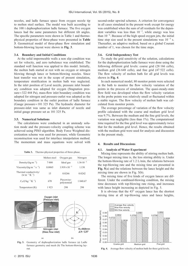
nozzles, and ladle furnace space from oxygen nozzle tip to molten steel surface. The model was built according to the 100 t dephosphorization ladle furnace. The five oxygen lances had the same parameters but different tilt angles. The specific parameters were shown in Table 1 and thermo-physical properties of three-phase were presented in Table 3. Geometrical model of three-phase flow simulation and bottom-blowing layout were shown in Fig. 3.
3.4. Boundary and Initial ConditionsAt the solid impermeable walls a non slip condition was
set for velocity, and zero turbulence was established. The standard wall function was applied to this model. Initially, the molten bath started at rest with no oxygen or nitrogen blowing through lance or bottom-blowing nozzles. Since heat transfer was not in the scope of present simulation, temperature stratification in molten bath was neglected. In the inlet position of Laval nozzle, pressure inlet bound-ary condition was adopted for oxygen (Stagnation pres-sure=322 444 Pa), mass-flow inlet boundary condition was adopted for nitrogen and pressure-outlet was adopted as the boundary condition in the outlet position of ladle furnace (Gauge pressure=101 325 Pa). The hydraulic diameter for pressure-inlet was same as inlet diameter of nozzle and initial gauge pressure set as 101 325 Pa.
3.5. Numerical SolutionsThe calculations were conducted in an unsteady solu-
tion mode and the pressure-velocity coupling scheme was achieved using PISO algorithm. Body Force Weighted dis-cretization scheme was used for pressure, while Geometric reconstruction was used for interface interpolation method. The momentum and mass equations were solved with
second-order upwind schemes. A criterion for convergence in all cases simulated in the present work except for energy was established when the sum of all residuals for the depen-dent variables was less than 10 −3, while energy was less than 10 −6. Because of the high speed oxygen jets, the initial time step size used in the present simulations was 10 −5 s. Thereafter, an adaptive method, based on a global Courant number of 1, was chosen for the time steps.
3.6. Grid Independency TestTo study the grid sensitivity of the solution, calculations
for the dephosphorization ladle furnace were done using the following different grid levels: coarse grid (28 166 cells), medium grid (36 648 cells), and fine grid (47 522 cells). The flow velocity of molten bath for all grid levels was shown in Fig. 4.
In each numerical model, 80 monitor points were selected in the bath to monitor the flow velocity variation of the points in the process of simulation. The quasi-steady-state flow field was developed when the flow velocity variation in the probe points was relatively small or fluctuated within a stable region. The flow velocity of molten bath was cal-culated from monitor points.
The average percentage of variation of the flow velocity profile calculated with the coarse and medium grid level was 9.7%. Between the medium and the fine grid levels, the variation was negligible (less than 1%). The computational time required for the fine grid level was approximately twice that for the medium grid level. Hence, the results obtained with the medium grid were used for analysis and discussion in the present study.
4. Results and Discussions
4.1. Analysis of Water ExperimentMixing time represents the ability of stirring molten bath.
The longer mixing time is, the less stirring ability is. Under the bottom-blowing rate of 1.2 L/min, the relations between the top-blowing rate and the mixing time are presented in Fig. 5(a) and the relations between the lance height and the mixing time are shown in Fig. 5(b).
The mixing time of five kinds of oxygen lances are dif-ferent. Under the combined-blowing condition, the mixing time decreases with top-blowing rate rising, and increases with lance height increasing as depicted in Fig. 5.
It is obvious that the 43° oxygen lance has the shortest mixing time at all top-blowing rates and lance heights,
Table 3. Thermo-physical properties of three-phase.
Molten steel Oxygen gas Nitrogen
Density/(kg·m −3) 7 000 Ideal gas 1.36·10 − 5
Viscosity/(kg·m −1·s −1) 0.0065 1.919×10 − 5 1.138
Thermal conductivity/(w·m −1·K−1) 15 0.0246 0.0242
CP/(J·kg −1·K−1) 670 Piecewise- polynomial 1 040.67
Temperature/(K) 1 923 298 298
Fig. 3. Geometry of dephosphorization ladle furnace (a) Ladle furnace geometry and mesh (b) The bottom-blowing lay-out. Fig. 4. Average flow velocity of molten bath for three grid levels.

ISIJ International, Vol. 55 (2015), No. 8
© 2015 ISIJ1637
which proves its stirring effect of molten bath is the best. Based on average values of five kinds of oxygen lances in Fig. 5(b), the slopes of the linear regression are 0.05, 0.18 and 0.20 when lance heights are in the range of 125 to 150 mm, 150 to 175 mm and 175 to 200 mm, respectively. That means the uptrend of mixing time would be accelerated with lance height increasing at the tested lance height.
It can be found from Fig. 5 that mixing time of 45° and 47° oxygen lances are shorter than that of 41° and 39° oxygen lances, respectively. It seems that the lance with tilt angle>43° could get better stirring effect than that with tilt angle<43°.
Impacting diameter represents the size of impacting area, which is an important indicator of contacting and mixing degrees of oxygen and molten bath. Figure 6 shows the impacting diameters of five kinds of oxygen lances at dif-ferent lance heights and gas flows.
As Fig. 6 presents, it can be known that as the lance height and flow rate rising, the impacting diameter increases. Based on average values of five kinds of oxygen lances in Fig. 6(b), the slopes of the linear regression are 0.46, 0.14 and 0.08 when lance heights are in the range of 125 to 150 mm, 150 to 175 mm and 175 to 200 mm, respectively. That means the uptrend of impacting diameter would be slow with lance height increasing. Based on analyzing of average slopes in Figs. 5(b) and 6(b), it seems that lance height=150 mm is inflection point of mixing time and impacting diameter at
the tested lance height.Unlike the decrease in mixing time, impacting diameters
of 39° and 41° oxygen lances are both bigger than those of 45° and 47° oxygen lances in Fig. 6. It seems that the lance with smaller tilt angle could form bigger impacting diam-eter. Although the 43° lance gets a bigger impacting diam-eter than 41° lance at the top-blowing rate=33.72 Nm3/h, the impacting diameter with the 43° lance is still the third.
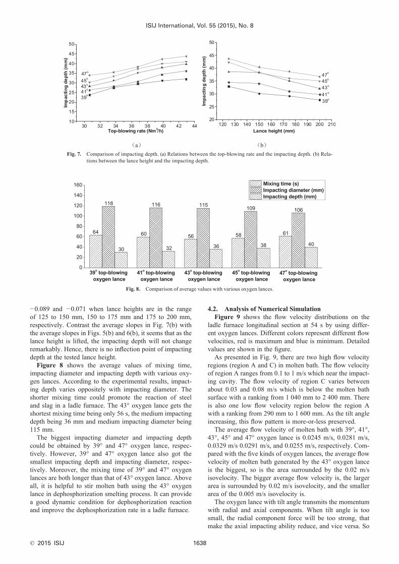
Figure 7 is the contrast of impacting depth of oxygen lance with various tilt angles at different lance heights and flow rates. From the above figures, it can be known as the flow rate increases, the impacting depth increases. More-over, as the lance height rises, the impacting depth reduces, which is opposite to impacting diameter.
The lower the lance height is, the shorter the distance from the nozzle tip to the surface of molten bath is, and the less the supersonic jet attenuation is. If the jet still has higher speed when reaching the molten bath surface, the impacting energy on molten bath will be greater, so the impacting depth is deeper. At the same lance height, with the increasing of gas flow, the jet kinetic energy increases, so the impacting ability is larger and the impacting depth is greater. Hence, smaller tilt angle will intensify the attenu-ation of jet velocity, which is against the improvement of impacting ability.
Based on average values of five kinds of oxygen lances in Fig. 7(b), the slopes of the linear regression are −0.086,
Fig. 5. Comparison of mixing time. (a) Relations between the top-blowing rate and the mixing time. (b) Relations between the lance height and the mixing time.
Fig. 6. Comparison of impacting diameter. (a) Relations between the top-blowing rate and the impacting diameter. (b) Relations between the lance height and the impacting diameter.
ISIJ International, Vol. 55 (2015), No. 8
© 2015 ISIJ 1638
−0.089 and −0.071 when lance heights are in the range of 125 to 150 mm, 150 to 175 mm and 175 to 200 mm, respectively. Contrast the average slopes in Fig. 7(b) with the average slopes in Figs. 5(b) and 6(b), it seems that as the lance height is lifted, the impacting depth will not change remarkably. Hence, there is no inflection point of impacting depth at the tested lance height.
Figure 8 shows the average values of mixing time, impacting diameter and impacting depth with various oxy-gen lances. According to the experimental results, impact-ing depth varies oppositely with impacting diameter. The shorter mixing time could promote the reaction of steel and slag in a ladle furnace. The 43° oxygen lance gets the shortest mixing time being only 56 s, the medium impacting depth being 36 mm and medium impacting diameter being 115 mm.
The biggest impacting diameter and impacting depth could be obtained by 39° and 47° oxygen lance, respec-tively. However, 39° and 47° oxygen lance also got the smallest impacting depth and impacting diameter, respec-tively. Moreover, the mixing time of 39° and 47° oxygen lances are both longer than that of 43° oxygen lance. Above all, it is helpful to stir molten bath using the 43° oxygen lance in dephosphorization smelting process. It can provide a good dynamic condition for dephosphorization reaction and improve the dephosphorization rate in a ladle furnace.
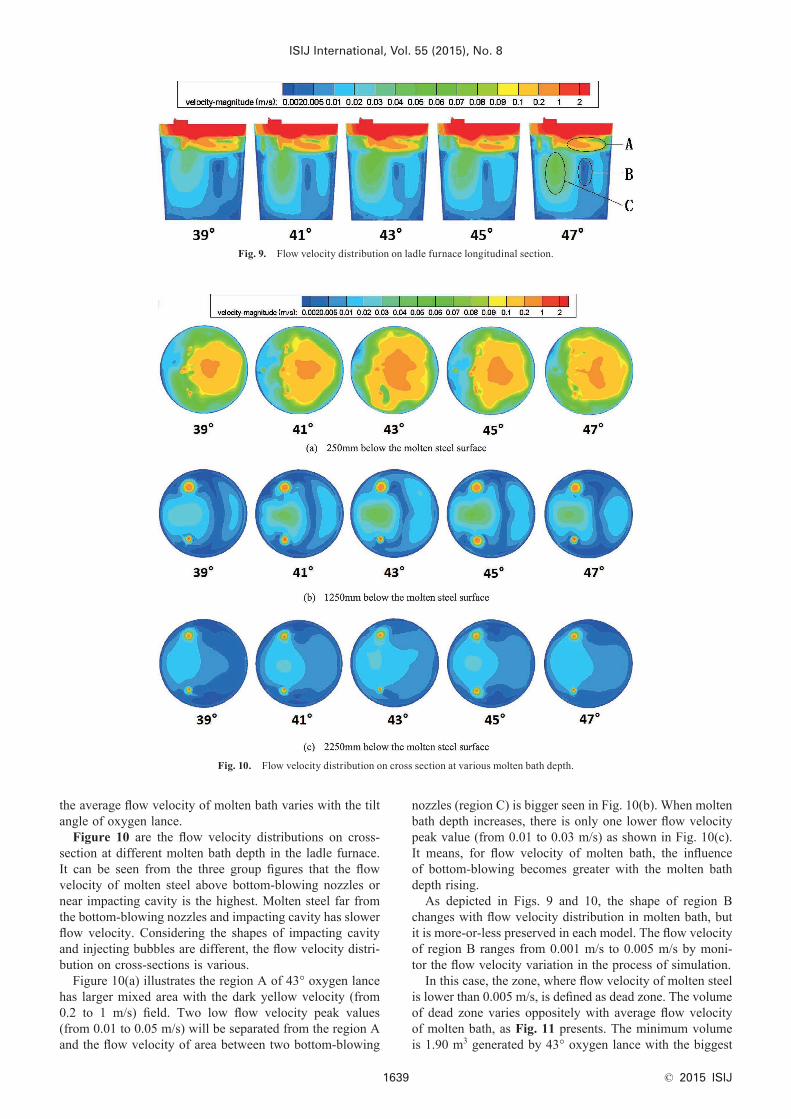
4.2. Analysis of Numerical SimulationFigure 9 shows the flow velocity distributions on the
ladle furnace longitudinal section at 54 s by using differ-ent oxygen lances. Different colors represent different flow velocities, red is maximum and blue is minimum. Detailed values are shown in the figure.
As presented in Fig. 9, there are two high flow velocity regions (region A and C) in molten bath. The flow velocity of region A ranges from 0.1 to 1 m/s which near the impact-ing cavity. The flow velocity of region C varies between about 0.03 and 0.08 m/s which is below the molten bath surface with a ranking from 1 040 mm to 2 400 mm. There is also one low flow velocity region below the region A with a ranking from 290 mm to 1 600 mm. As the tilt angle increasing, this flow pattern is more-or-less preserved.
The average flow velocity of molten bath with 39°, 41°, 43°, 45° and 47° oxygen lance is 0.0245 m/s, 0.0281 m/s, 0.0329 m/s 0.0291 m/s, and 0.0255 m/s, respectively. Com-pared with the five kinds of oxygen lances, the average flow velocity of molten bath generated by the 43° oxygen lance is the biggest, so is the area surrounded by the 0.02 m/s isovelocity. The bigger average flow velocity is, the larger area is surrounded by 0.02 m/s isovelocity, and the smaller area of the 0.005 m/s isovelocity is.
The oxygen lance with tilt angle transmits the momentum with radial and axial components. When tilt angle is too small, the radial component force will be too strong, that make the axial impacting ability reduce, and vice versa. So
Fig. 7. Comparison of impacting depth. (a) Relations between the top-blowing rate and the impacting depth. (b) Rela-tions between the lance height and the impacting depth.
Fig. 8. Comparison of average values with various oxygen lances.
ISIJ International, Vol. 55 (2015), No. 8
© 2015 ISIJ1639
the average flow velocity of molten bath varies with the tilt angle of oxygen lance.
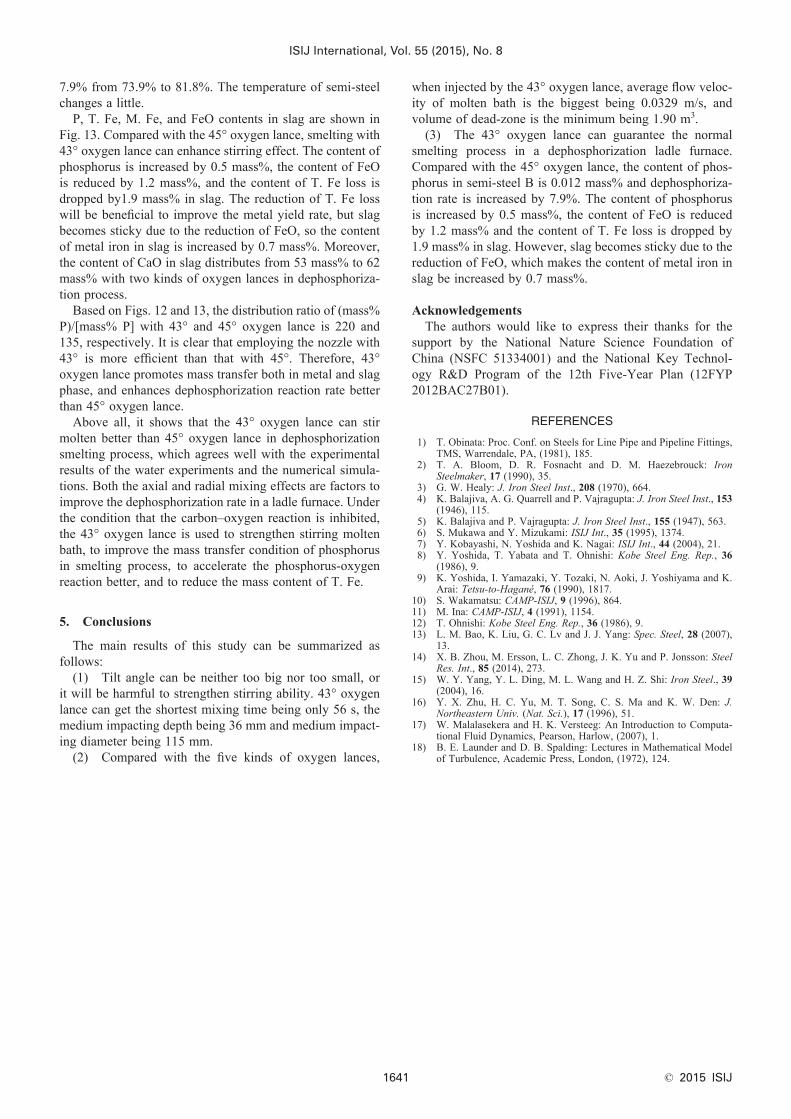
Figure 10 are the flow velocity distributions on cross-section at different molten bath depth in the ladle furnace. It can be seen from the three group figures that the flow velocity of molten steel above bottom-blowing nozzles or near impacting cavity is the highest. Molten steel far from the bottom-blowing nozzles and impacting cavity has slower flow velocity. Considering the shapes of impacting cavity and injecting bubbles are different, the flow velocity distri-bution on cross-sections is various.
Figure 10(a) illustrates the region A of 43° oxygen lance has larger mixed area with the dark yellow velocity (from 0.2 to 1 m/s) field. Two low flow velocity peak values (from 0.01 to 0.05 m/s) will be separated from the region A and the flow velocity of area between two bottom-blowing
nozzles (region C) is bigger seen in Fig. 10(b). When molten bath depth increases, there is only one lower flow velocity peak value (from 0.01 to 0.03 m/s) as shown in Fig. 10(c). It means, for flow velocity of molten bath, the influence of bottom-blowing becomes greater with the molten bath depth rising.
As depicted in Figs. 9 and 10, the shape of region B changes with flow velocity distribution in molten bath, but it is more-or-less preserved in each model. The flow velocity of region B ranges from 0.001 m/s to 0.005 m/s by moni-tor the flow velocity variation in the process of simulation.
In this case, the zone, where flow velocity of molten steel is lower than 0.005 m/s, is defined as dead zone. The volume of dead zone varies oppositely with average flow velocity of molten bath, as Fig. 11 presents. The minimum volume is 1.90 m3 generated by 43° oxygen lance with the biggest
Fig. 9. Flow velocity distribution on ladle furnace longitudinal section.
Fig. 10. Flow velocity distribution on cross section at various molten bath depth.

ISIJ International, Vol. 55 (2015), No. 8
© 2015 ISIJ 1640
flow velocity being 0.0329 m/s. The maximum volume is 4.21 m3 generated by 39° oxygen lance with the minimum flow velocity being 0.0245 m/s.
The results indicate that suitable tilt angle can prevent flow velocity stratification in the centre of the molten bath, and help reduce the volume of dead zone. When injecting by the 43° oxygen lance, average flow velocity of molten bath is the biggest being 0.0329 m/s, and volume of dead-zone is the minimum being 1.90 m3.
4.3. Industrial Application ResearchThrough water experiment and numerical simulation
study, injecting by 43° oxygen lance can improve stirring effect on molten bath in the dephosphorization process. In order to study metallurgical effects and technical indicators of the oxygen lance with tilt angle for dephosphorization, both the 43° and 45° oxygen lances were adopted in a 100 t ladle furnace. There were 102 heats collected in the indus-trial smelting process, including 51 heats with 43° oxygen lance and 51 heats with 45° oxygen lance, and the operation conditions were same with both the 43° and 45° oxygen lances. Semi-steel component, dephosphorization rate and T. Fe loss were analyzed in this research.
There are two kinds of semi-steel in smelting process: semi-steel A (prior to dephosphorization), and semi-steel B (after dephosphorization). Figure 12 illustrates the dis-tribution of phosphorus in semi-steel B using two kinds of oxygen lances for dephosphorization. When the 43° oxygen lance is used for dephosphorization, the content of phosphorus in semi-steel B distributes from 0.010 mass% to 0.042 mass%. And the content of phosphorus in semi-steel B is from 0.017 mass% to 0.052 mass% with the 45° oxygen lance.
According to components of slag layer and steelmak-ing temperature, equilibrium phosphorus content of each smelting heat has been calculated using Eq. (1). It should be noticed that the term of (mass% T. Fe) in Eq. (1) is deduced from FeO which does not involve M. Fe shown in Fig. 13. The content of equilibrium phosphorus in semi-steel B is 4.3×10 −4 mass% using 43° oxygen lance. And the content of equilibrium phosphorus in semi-steel B is 3.1×10 −4 mass% with the 45° oxygen lance. It is obvi-ous that both equilibrium phosphorus contents are most importantly negligibly small. This fact can prove that the reaction rate with 43° oxygen lance can be enhanced due to
the efficient agitation as observed by the water experiments and the simulations.
The average components, temperatures of semi-steel, and smelting time are shown in Table 4. The content of tita-nium in semi-steel A is limited, which means influences of dephosphorization rate could be negligible. When smelting with two different oxygen lances, the conditions of semi-steel A are fundamentally the same.
The content of phosphorus in semi-steel B is dropped by 0.012 mass% injecting by the 43° oxygen lance. The dephosphorization rate in the ladle furnace is improved by
Fig. 11. The formula of average flow velocity of bath and volume of dead zone.
Fig. 12. Distribution of phosphorus contents in semi-steel B.
Fig. 13. Distribution of P, T. Fe, M. Fe and FeO contents in slag.
Table 4. Average values analysis of semi-steels with two kinds of oxygen lances.
Label 43° oxygen lance 45° oxygen lance
Semi-steel A
C (mass%) 3.85 3.82
Si (mass%) 0.004 0.003
Ti (mass%) 0.003 0.003
P (mass%) 0.137 0.142
Temperature (°C) 1 303 1 307
Semi-steel B
C (mass%) 3.58 3.57
P (mass%) 0.025 0.037
Temperature (°C) 1 318 1 319
Smelting time (min) 6 6
ISIJ International, Vol. 55 (2015), No. 8
© 2015 ISIJ1641
7.9% from 73.9% to 81.8%. The temperature of semi-steel changes a little.
P, T. Fe, M. Fe, and FeO contents in slag are shown in Fig. 13. Compared with the 45° oxygen lance, smelting with 43° oxygen lance can enhance stirring effect. The content of phosphorus is increased by 0.5 mass%, the content of FeO is reduced by 1.2 mass%, and the content of T. Fe loss is dropped by1.9 mass% in slag. The reduction of T. Fe loss will be beneficial to improve the metal yield rate, but slag becomes sticky due to the reduction of FeO, so the content of metal iron in slag is increased by 0.7 mass%. Moreover, the content of CaO in slag distributes from 53 mass% to 62 mass% with two kinds of oxygen lances in dephosphoriza-tion process.
Based on Figs. 12 and 13, the distribution ratio of (mass% P)/[mass% P] with 43° and 45° oxygen lance is 220 and 135, respectively. It is clear that employing the nozzle with 43° is more efficient than that with 45°. Therefore, 43° oxygen lance promotes mass transfer both in metal and slag phase, and enhances dephosphorization reaction rate better than 45° oxygen lance.
Above all, it shows that the 43° oxygen lance can stir molten better than 45° oxygen lance in dephosphorization smelting process, which agrees well with the experimental results of the water experiments and the numerical simula-tions. Both the axial and radial mixing effects are factors to improve the dephosphorization rate in a ladle furnace. Under the condition that the carbon–oxygen reaction is inhibited, the 43° oxygen lance is used to strengthen stirring molten bath, to improve the mass transfer condition of phosphorus in smelting process, to accelerate the phosphorus-oxygen reaction better, and to reduce the mass content of T. Fe.
5. Conclusions
The main results of this study can be summarized as follows:
(1) Tilt angle can be neither too big nor too small, or it will be harmful to strengthen stirring ability. 43° oxygen lance can get the shortest mixing time being only 56 s, the medium impacting depth being 36 mm and medium impact-ing diameter being 115 mm.
(2) Compared with the five kinds of oxygen lances,
when injected by the 43° oxygen lance, average flow veloc-ity of molten bath is the biggest being 0.0329 m/s, and volume of dead-zone is the minimum being 1.90 m3.
(3) The 43° oxygen lance can guarantee the normal smelting process in a dephosphorization ladle furnace. Compared with the 45° oxygen lance, the content of phos-phorus in semi-steel B is 0.012 mass% and dephosphoriza-tion rate is increased by 7.9%. The content of phosphorus is increased by 0.5 mass%, the content of FeO is reduced by 1.2 mass% and the content of T. Fe loss is dropped by 1.9 mass% in slag. However, slag becomes sticky due to the reduction of FeO, which makes the content of metal iron in slag be increased by 0.7 mass%.
AcknowledgementsThe authors would like to express their thanks for the
support by the National Nature Science Foundation of China (NSFC 51334001) and the National Key Technol-ogy R&D Program of the 12th Five-Year Plan (12FYP 2012BAC27B01).
REFERENCES
1) T. Obinata: Proc. Conf. on Steels for Line Pipe and Pipeline Fittings, TMS, Warrendale, PA, (1981), 185.
2) T. A. Bloom, D. R. Fosnacht and D. M. Haezebrouck: Iron Steelmaker, 17 (1990), 35.
3) G. W. Healy: J. Iron Steel Inst., 208 (1970), 664.4) K. Balajiva, A. G. Quarrell and P. Vajragupta: J. Iron Steel Inst., 153
(1946), 115.5) K. Balajiva and P. Vajragupta: J. Iron Steel Inst., 155 (1947), 563.6) S. Mukawa and Y. Mizukami: ISIJ Int., 35 (1995), 1374.7) Y. Kobayashi, N. Yoshida and K. Nagai: ISIJ Int., 44 (2004), 21.8) Y. Yoshida, T. Yabata and T. Ohnishi: Kobe Steel Eng. Rep., 36
(1986), 9.9) K. Yoshida, I. Yamazaki, Y. Tozaki, N. Aoki, J. Yoshiyama and K.
Arai: Tetsu-to-Hagané, 76 (1990), 1817.10) S. Wakamatsu: CAMP-ISIJ, 9 (1996), 864.11) M. Ina: CAMP-ISIJ, 4 (1991), 1154.12) T. Ohnishi: Kobe Steel Eng. Rep., 36 (1986), 9.13) L. M. Bao, K. Liu, G. C. Lv and J. J. Yang: Spec. Steel, 28 (2007),
13.14) X. B. Zhou, M. Ersson, L. C. Zhong, J. K. Yu and P. Jonsson: Steel
Res. Int., 85 (2014), 273.15) W. Y. Yang, Y. L. Ding, M. L. Wang and H. Z. Shi: Iron Steel., 39
(2004), 16.16) Y. X. Zhu, H. C. Yu, M. T. Song, C. S. Ma and K. W. Den: J.
Northeastern Univ. (Nat. Sci.), 17 (1996), 51.17) W. Malalasekera and H. K. Versteeg: An Introduction to Computa-
tional Fluid Dynamics, Pearson, Harlow, (2007), 1.18) B. E. Launder and D. B. Spalding: Lectures in Mathematical Model
of Turbulence, Academic Press, London, (1972), 124.