Embed Size (px)
Citation preview

Simulation Model of the Temperature Inside an Intermittent Kiln of the Red Ceramic Industry
Lima, Y.R.S1*;Morais, A.S.C1;Ferreira, C.N.1;Souza, B.L.1 1 Federal Fluminense Institute
Dr. Siqueira Street, 273 – Parque Dom Bosco, Campos dos Goytacazes – RJ
Abstract The ceramic industry in Brazil is characterized by the low level of automation
applied in its production process and by the cheap and low-skilled workforce. Among
the obstacles observed for the implementation of automation in Brazilian ceramics, it
is worth mentioning its high cost and the low qualification of the workforce at the
operational level. A simplified and low-cost Feed Control System (FCS) for
intermittent kilns is proposed so that the firing is more homogeneous, consumes less
fuel and, consequently, produces fewer environmental impacts. Therefore, the
objective of this paper is to demonstrate the development of the simulation and the
behavior of the FCS system. The simulation is done using the hardware-in-the-loop
technique, where the system plan and its interaction are recreated in the Simulink of
Matlab Software through blocks diagrams and the control system is executed in a
PLC through control logic. The results (burn curve) of the simulation allow to state
that the system behaves in a more stable way and the fuel expense decreases
considerably when compared to the real system. The process of system simulation is
very important to the industries, especially of red ceramics, so that it is possible to
know how the system will behave before being literally executed and then avoid
unnecessary expenses.
Keywords: Simulation, clayey ceramics, temperature, energy efficiency, intermittent
kiln.
7th International Congress on Ceramics & 62º Congresso Brasileiro de CerâmicaJune 17-21, 2018, Foz do Iguaçu - PR - Brazil
976
Introduction
The ceramic industry activity is one of the main industrial activities in Brazil, that
is the 2nd largest producer of ceramic coating as well as the 2nd largest consumer
market in the world, only spotted behind China. In addition to that, in recent years,
Brazil has surpassed important markets such as Italy and Spain [1].
In order to implement new technologies in the industry, it is necessary to break
down some barriers that prevent the development. Due to small and medium-sized
companies, for the most part their production process is quite artisanal and
exceeded, without controlling the main variables in an automatic way, where the
whole process is manually managed based on the experience of the labor force [2].
This way, the quality of the final product can be affected by the linearity of the
conditions in the production process stages, so the production of batches of parts
can differ significantly and not match the technical requirements standard defined.
These difficulties can also be found in the ceramist pole located in Campos
dos Goytacazes, north of Rio de Janeiro state. Most of the cities in this region have
the capacity for innovation, both in terms of product and process. The main factors
for this, are mainly the lack of professionalization of the labor force, as already
mentioned, besides the lack of innovative vision by the owners, once their processes
have been working that way for years [3].
In order for these difficulties to be overcome, there are some actions that need
to be taken by the ceramists, as an improvement of the production process by
establishing the automation and control of the system. Such measures require time
and financial resources. So, the steps of the production process that directly interfere
the final product should be prioritized, as well as considering low-cost alternatives for
the implementation of the control.
The stage of the productive process that can be considered as critical and
then prioritized, once it is about controlling, is the burning stage. It is on this process
that technical and static capabilities are conferred to the product, through sintering,
that generates the physical-chemical transformation in the ceramic material [4].
Due to this fact and with all financial and structural impasses faced by the
ceramic sector, the critical stage of the process has to be prioritized and the use of
alternatives to improve the productive process in intermediate levels of automation
7th International Congress on Ceramics & 62º Congresso Brasileiro de CerâmicaJune 17-21, 2018, Foz do Iguaçu - PR - Brazil
977
has to be considered. These options are simple, easy to implement, maintain, and
result in a direct improvement related to the productive process.
Materials and methods This section of the research demonstrates in 3 phases of the materials and
methods used to elaborate the project. In the first one, it is exposed the
characteristics of the kiln where the project was conceived. In the second, the control
system is detailed, clarifying its interaction with the system. Finally, it is shown how
the system simulation is done, detailing from the part of the communication between
the softwares and hardware used in the project to all the algorithms and diagrams
made during its execution.
The object of study on this research is an intermittent domed kiln located at
Arte Cerâmica Sardinha, in the district of São Sebastião, municipality of Campos dos
Goytacazes.
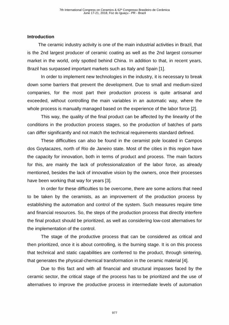
The kiln used to develop the project has 6.83 meters in diameter, 2.2 meters in
height from the ground up to the load and 3.3 meters from the ground to the center of
the dome, in addition it has 4 furnaces and two doors of 1.84 meters each one, the
width of the kiln wall is 1.20 meters. In figure 1, one of the doors and two of its four
furnaces can be seen.
Figure 1 – Intermittent domed kiln
The kiln operates in 3 phases; the first one is the heating of internal atmosphere
to the desired temperature, after reaching that temperature, the furnace supply is
decreased in order to maintain the constant value for a determined period of time and
finally the kiln is cooled so that the load can be handled.
7th International Congress on Ceramics & 62º Congresso Brasileiro de CerâmicaJune 17-21, 2018, Foz do Iguaçu - PR - Brazil
978
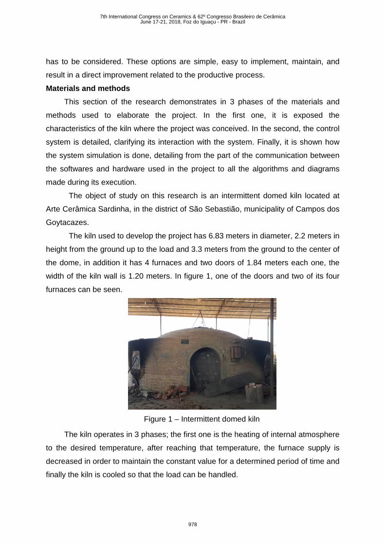
The proposed feed control system (FCS) focuses on the temperature control
of the internal atmosphere of the kiln. In order for this to be possible, the temperature
is measured through thermocouples placed inside the kiln. There are 6 type K
thermocouples installed, they were placed as shown in figure 2.
Figure 2 – Thermocouples placed on the kiln
These thermocouples send information about temperature to a Programmable
Logic Controller (P.L.C.) that has the control logic. In order to be manipulated by the
P.L.C, these temperature data are pre-purchased by a Phoenix Contact Mini MCR-
SL-TC-UI-NC thermocouple module that performs the reception, noise treatment,
reference joint compensation and scanning through a 12-bit analog-to-digital
converter, sending to the Arduino the temperature values with a resolution of 0.25° C.
Considering the values of the temperature the process control can be
automatic or manual. Automatically, any increase of the temperature and control in a
certain value is processed automatically through the control logic implemented in the
P.L.C. Manually, the set-point related to the temperature and the "output" value of the
frequency inverter for the sawdust and air-blower machine are defined by the
operator, remaining on this value while the operator judge it is necessary.
In automatic mode, the P.L.C. acts in the process through the addition or not
of fuel in the furnaces besides the addition of oxidizer (air). The fuel used in the
studied kiln is the sawdust. This fuel is sent to the interior of the furnace through a
sawdust feeding machine that has a motor that rotates a kind of toothed gearing
responsible for throwing the fuel into the furnace. This way you can control the
rotation speed and consequently the amount of sawdust that will feed the furnace,
7th International Congress on Ceramics & 62º Congresso Brasileiro de CerâmicaJune 17-21, 2018, Foz do Iguaçu - PR - Brazil
979
through its connection to a frequency inverter that regulates the frequency will reach
the machine.
According to the temperature information that comes from the thermocouples
and with the interaction of these data in the control logic, the P.L.C. will have the
motor rotating faster or slower and this way more or less sawdust in the furnaces.The
same goes for adding air to the interior of the furnace. The relationship between fuel
and oxidizer is described in the control logic.
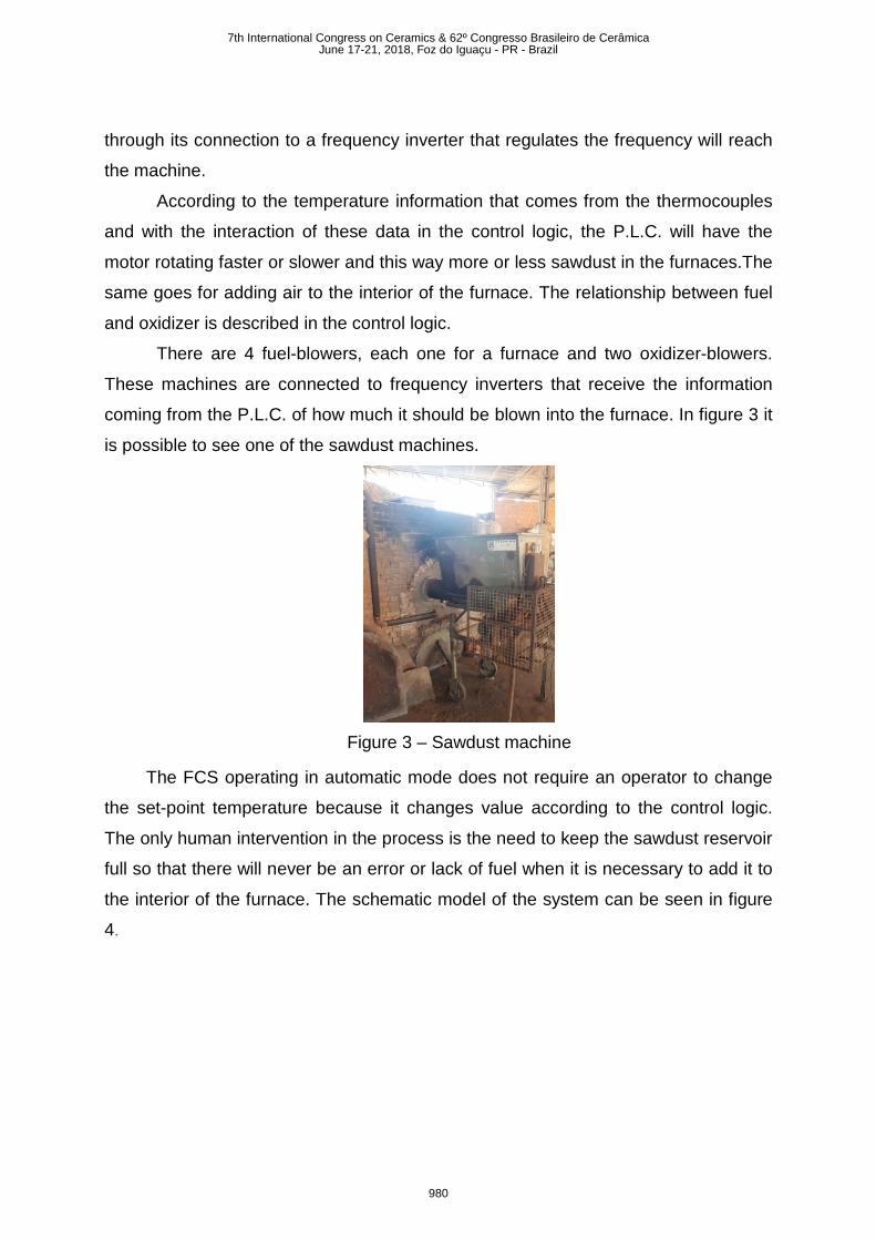
There are 4 fuel-blowers, each one for a furnace and two oxidizer-blowers.
These machines are connected to frequency inverters that receive the information
coming from the P.L.C. of how much it should be blown into the furnace. In figure 3 it
is possible to see one of the sawdust machines.
Figure 3 – Sawdust machine
The FCS operating in automatic mode does not require an operator to change
the set-point temperature because it changes value according to the control logic.
The only human intervention in the process is the need to keep the sawdust reservoir
full so that there will never be an error or lack of fuel when it is necessary to add it to
the interior of the furnace. The schematic model of the system can be seen in figure
4.
7th International Congress on Ceramics & 62º Congresso Brasileiro de CerâmicaJune 17-21, 2018, Foz do Iguaçu - PR - Brazil
980
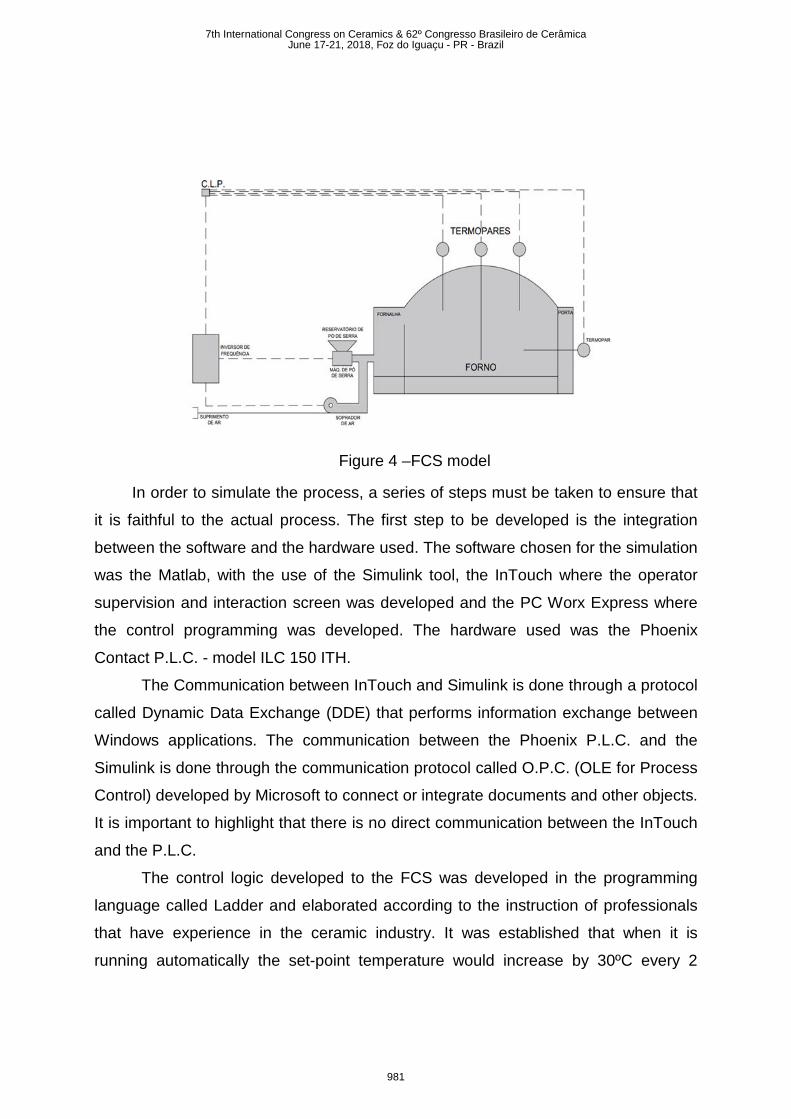
Figure 4 –FCS model
In order to simulate the process, a series of steps must be taken to ensure that
it is faithful to the actual process. The first step to be developed is the integration
between the software and the hardware used. The software chosen for the simulation
was the Matlab, with the use of the Simulink tool, the InTouch where the operator
supervision and interaction screen was developed and the PC Worx Express where
the control programming was developed. The hardware used was the Phoenix
Contact P.L.C. - model ILC 150 ITH.
The Communication between InTouch and Simulink is done through a protocol
called Dynamic Data Exchange (DDE) that performs information exchange between
Windows applications. The communication between the Phoenix P.L.C. and the
Simulink is done through the communication protocol called O.P.C. (OLE for Process
Control) developed by Microsoft to connect or integrate documents and other objects.
It is important to highlight that there is no direct communication between the InTouch
and the P.L.C.
The control logic developed to the FCS was developed in the programming
language called Ladder and elaborated according to the instruction of professionals
that have experience in the ceramic industry. It was established that when it is
running automatically the set-point temperature would increase by 30ºC every 2
7th International Congress on Ceramics & 62º Congresso Brasileiro de CerâmicaJune 17-21, 2018, Foz do Iguaçu - PR - Brazil
981
hours until reaching the maximum temperature selected by the operator, being the
Top Thermocouple (T9) defined as a parameter to increase the temperature.
The burning time varies according to the maximum temperature set by the
operator what will affect the amount of increments the temperature will suffer.
However, from expert information the average burning time determined on the
simulation was 100 hours, with 50 hours for heating to the maximum temperature of
900ºC and 50h controlling this value. After this, the process goes into natural cooling
and the automatic control system is switched off.
For the simulation to occur, it is necessary to implement a block diagram in
Simulink that lists all the system variables with the transfer function that correctly
relates the input and output of the process.
The control strategy chosen was the feedback control, simply known as
"feedback", where only the information of the Thermocouple is used to compare with
the reference value of the temperature that generates an error and then causes an
action of control that interacts with the system plant, returning a value that will be
read back by the sensor and sent for comparison [5].
According to the idea of how a feedback control system behaves, it was
necessary to obtain the transfer function that relates the amount of fuel to the
temperature. This way, an experiment was performed where the initial temperature of
the system with 0% of fuel was measured. After this, the fuel machine and the air-
blower with maximum load were placed to verify at which temperature it would
stabilize. It is important to note that the procedure was performed with load inside the
kiln.
By analyzing the system behavior, it can be verified that it behaves like a
system of order 1. It is known that a first order system behaves according to equation
A. 𝐶𝐶(𝑠𝑠)𝑅𝑅(𝑆𝑆) =
𝐾𝐾𝑇𝑇𝑆𝑆+ 1
(A)
This way, in order to find the time constant T, it is necessary to check in the
graph the moment when the system reaches 63.2% of the final value. So, we used
Matlab. The values were placed in a matrix and plotted on a graph. By knowing that
the final value of the temperature is 200 ° C and the initial value is 130 ° C, the value
corresponding to 63.2% in that temperature range is 174.2 ° C. The time the system
7th International Congress on Ceramics & 62º Congresso Brasileiro de CerâmicaJune 17-21, 2018, Foz do Iguaçu - PR - Brazil
982
reaches this temperature is approximately 2880s. In this way the transfer function
obtained can be seen in equation B. 𝐶𝐶(𝑠𝑠)𝑅𝑅(𝑆𝑆) =
702880𝑆𝑆 + 1
(B)
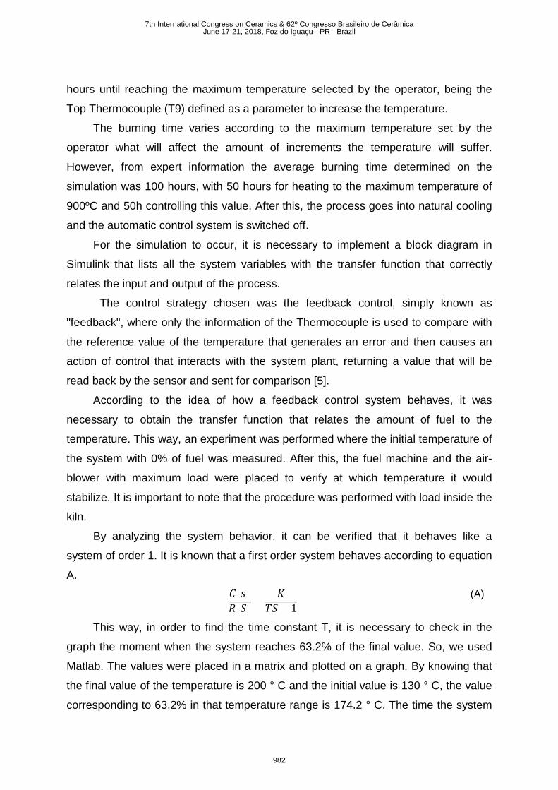
For comparison of the actual system with the transfer function, the behavior of
the real system and the response to a step-type input of the transfer function was
plotted on a graph. Figure 5 shows the comparison of the transfer function with the
current burning of the kiln and a very similar behavior can be checked.
Figure 5 - Comparison transfer function x Real temperature
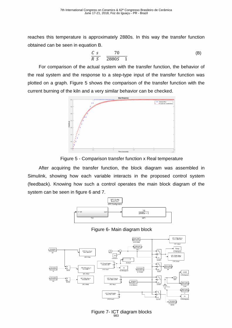
After acquiring the transfer function, the block diagram was assembled in
Simulink, showing how each variable interacts in the proposed control system
(feedback). Knowing how such a control operates the main block diagram of the
system can be seen in figure 6 and 7.
Figure 6- Main diagram block
Figure 7- ICT diagram blocks
7th International Congress on Ceramics & 62º Congresso Brasileiro de CerâmicaJune 17-21, 2018, Foz do Iguaçu - PR - Brazil
983
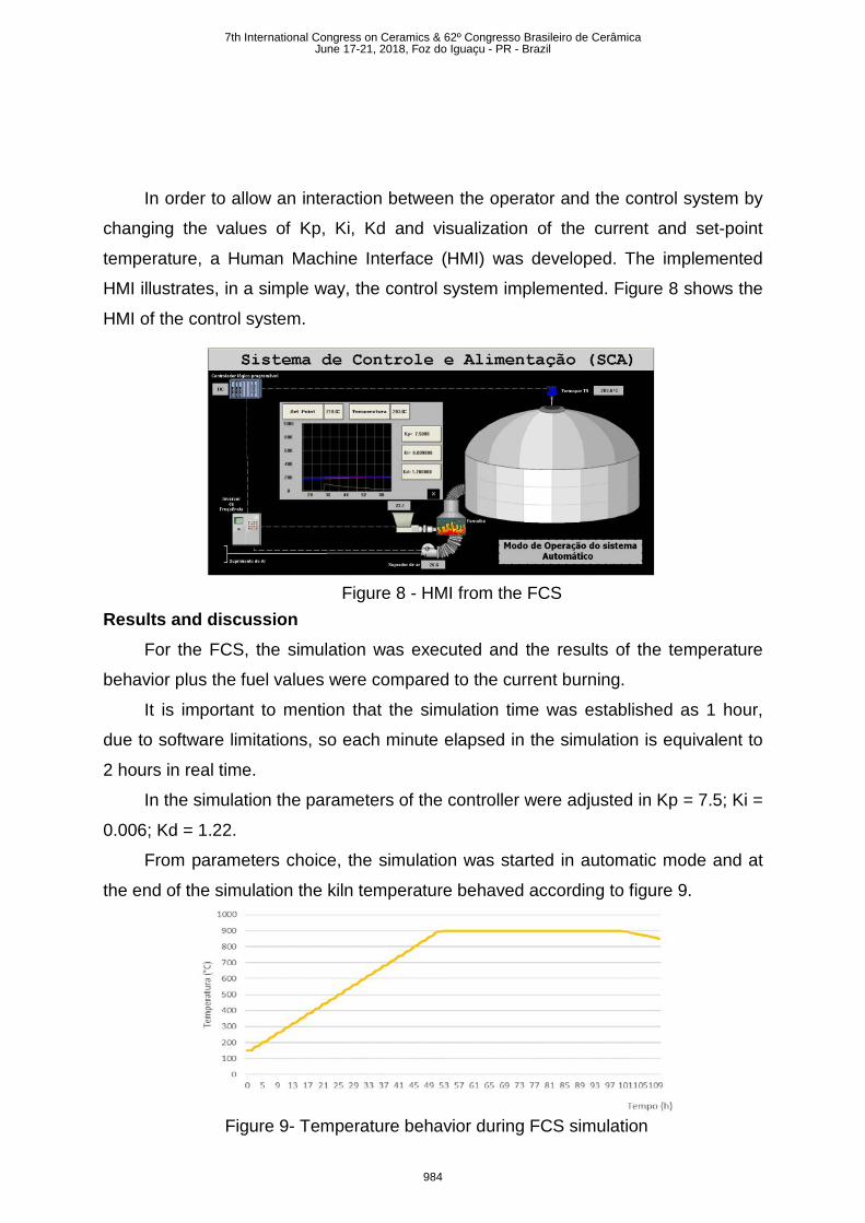
Figure 8 - HMI from the FCS
Figure 9- Temperature behavior during FCS simulation
In order to allow an interaction between the operator and the control system by
changing the values of Kp, Ki, Kd and visualization of the current and set-point
temperature, a Human Machine Interface (HMI) was developed. The implemented
HMI illustrates, in a simple way, the control system implemented. Figure 8 shows the
HMI of the control system.
Results and discussion For the FCS, the simulation was executed and the results of the temperature
behavior plus the fuel values were compared to the current burning.
It is important to mention that the simulation time was established as 1 hour,
due to software limitations, so each minute elapsed in the simulation is equivalent to
2 hours in real time.
In the simulation the parameters of the controller were adjusted in Kp = 7.5; Ki =
0.006; Kd = 1.22.
From parameters choice, the simulation was started in automatic mode and at
the end of the simulation the kiln temperature behaved according to figure 9.
7th International Congress on Ceramics & 62º Congresso Brasileiro de CerâmicaJune 17-21, 2018, Foz do Iguaçu - PR - Brazil
984
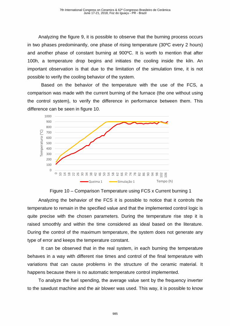
Analyzing the figure 9, it is possible to observe that the burning process occurs
in two phases predominantly, one phase of rising temperature (30ºC every 2 hours)
and another phase of constant burning at 900ºC. It is worth to mention that after
100h, a temperature drop begins and initiates the cooling inside the kiln. An
important observation is that due to the limitation of the simulation time, it is not
possible to verify the cooling behavior of the system.
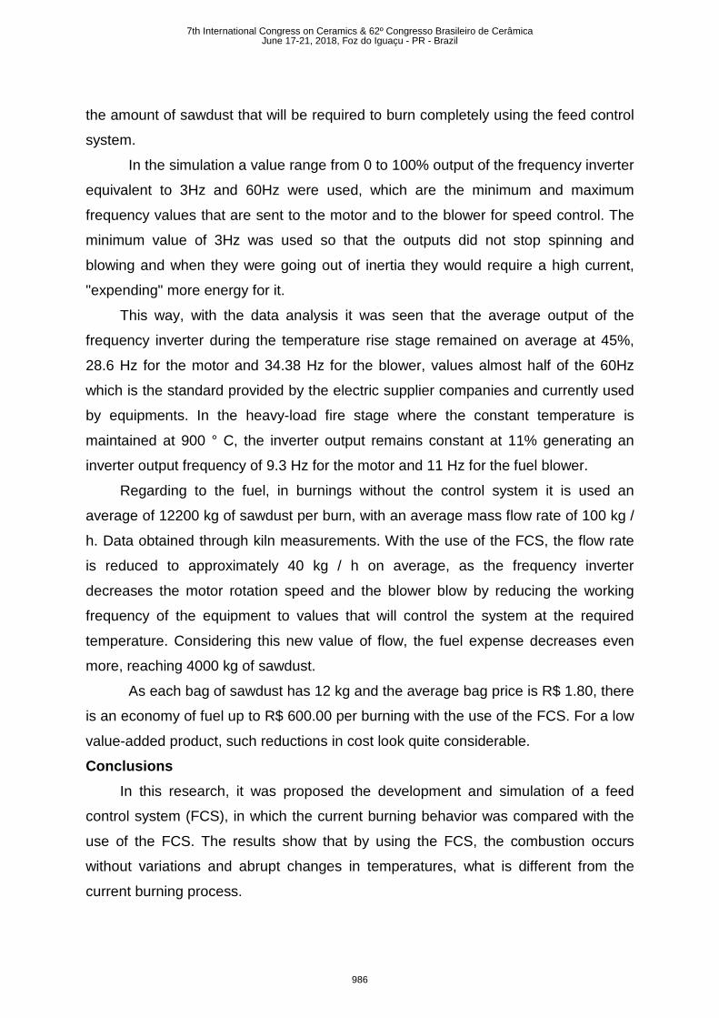
Based on the behavior of the temperature with the use of the FCS, a
comparison was made with the current burning of the furnace (the one without using
the control system), to verify the difference in performance between them. This
difference can be seen in figure 10.
Figure 10 – Comparison Temperature using FCS x Current burning 1
Analyzing the behavior of the FCS it is possible to notice that it controls the
temperature to remain in the specified value and that the implemented control logic is
quite precise with the chosen parameters. During the temperature rise step it is
raised smoothly and within the time considered as ideal based on the literature.
During the control of the maximum temperature, the system does not generate any
type of error and keeps the temperature constant.
It can be observed that in the real system, in each burning the temperature
behaves in a way with different rise times and control of the final temperature with
variations that can cause problems in the structure of the ceramic material. It
happens because there is no automatic temperature control implemented.
To analyze the fuel spending, the average value sent by the frequency inverter
to the sawdust machine and the air blower was used. This way, it is possible to know
0100200300400500600700800900
1000
0 10 14 18 22 26 30 34 38 42 46 50 54 58 62 66 70 74 78 82 86 90 94 98 102
106
Tem
pera
tura
(°C)
Tempo (h)Queima 1 Simulação 1
7th International Congress on Ceramics & 62º Congresso Brasileiro de CerâmicaJune 17-21, 2018, Foz do Iguaçu - PR - Brazil
985
the amount of sawdust that will be required to burn completely using the feed control
system.
In the simulation a value range from 0 to 100% output of the frequency inverter
equivalent to 3Hz and 60Hz were used, which are the minimum and maximum
frequency values that are sent to the motor and to the blower for speed control. The
minimum value of 3Hz was used so that the outputs did not stop spinning and
blowing and when they were going out of inertia they would require a high current,
"expending" more energy for it.
This way, with the data analysis it was seen that the average output of the
frequency inverter during the temperature rise stage remained on average at 45%,
28.6 Hz for the motor and 34.38 Hz for the blower, values almost half of the 60Hz
which is the standard provided by the electric supplier companies and currently used
by equipments. In the heavy-load fire stage where the constant temperature is
maintained at 900 ° C, the inverter output remains constant at 11% generating an
inverter output frequency of 9.3 Hz for the motor and 11 Hz for the fuel blower.
Regarding to the fuel, in burnings without the control system it is used an
average of 12200 kg of sawdust per burn, with an average mass flow rate of 100 kg /
h. Data obtained through kiln measurements. With the use of the FCS, the flow rate
is reduced to approximately 40 kg / h on average, as the frequency inverter
decreases the motor rotation speed and the blower blow by reducing the working
frequency of the equipment to values that will control the system at the required
temperature. Considering this new value of flow, the fuel expense decreases even
more, reaching 4000 kg of sawdust.
As each bag of sawdust has 12 kg and the average bag price is R$ 1.80, there
is an economy of fuel up to R$ 600.00 per burning with the use of the FCS. For a low
value-added product, such reductions in cost look quite considerable.
Conclusions In this research, it was proposed the development and simulation of a feed
control system (FCS), in which the current burning behavior was compared with the
use of the FCS. The results show that by using the FCS, the combustion occurs
without variations and abrupt changes in temperatures, what is different from the
current burning process.
7th International Congress on Ceramics & 62º Congresso Brasileiro de CerâmicaJune 17-21, 2018, Foz do Iguaçu - PR - Brazil
986
During the simulation of the FCS, the parameters for the PID controller were
defined and it behaved with a very satisfactory temperature control, because, as it
can be seen in figures 12 and 13, the temperature increase is carried out in a non-
abrupt manner, within the time required to acquire structural and aesthetic properties,
reducing the chances of structural deformities and increasing the standardization of
the final product at each burn. During the stage of heavy-load fire, the temperature
remains constant at 900ºC without variations.
The FCS is able to provide to the burning process, a reduction of fuel and
consequently a reduction of production cost that can reach R$ 600 per burn.
References [1] ANICER, - Associação Nacional da Industrial Cerâmica. Recovered from http://portal.anicer.com.br/setor/, 2016. [2] BRAGA, W. A.; SANTOS, M. W. L. C.; SALES, J. C. Qualidade na Indústria de Cerâmica Vermelha: Medidas e Alternativas para o Controle Dimensional. Cerâmica Industrial, 21(5–6), p. 40–43, 2016. [3] ROCHA, A. F.; PALMA, M. A. M. Gestão da inovação e capacidade competitiva: uma análise não paramétrica no setor cerâmico de Campos dos Goytacazes, RJ. Cerâmica, 58(346), p. 244–252, 2012 [4] PAIVA FILHO, E.; AGOSTINHO, R.; JÚNIOR, J.; BEZERRA, F.; AQUINO, P.Cooperação Internacional E Desenvolvimento Tecnológico: Controle Do Processo De Queima Em Fornos Hoffmann Para Cerâmica Vermelha. Presented at the Brazilian Congress of Engineering Education, Brasília, 2004. [5] OGATA, K. Engenharia de controle moderno. 4o ed. São Paulo: Pearson Prentice Hall, 2007.s
7th International Congress on Ceramics & 62º Congresso Brasileiro de CerâmicaJune 17-21, 2018, Foz do Iguaçu - PR - Brazil
987


![Propagation on 630-Meters and 2200-Meters Carl ...€¦ · Propagation on 630-Meters and 2200-Meters ... extraordinary wave [note 4]. ... from your antenna to the characteristic wave](https://img.pdfslide.net/doc/110x75/5f3d34451ceef234f76719be/propagation-on-630-meters-and-2200-meters-carl-propagation-on-630-meters-and.jpg)