Embed Size (px)
Citation preview

97
Simulation of Free Piston Linear Engine Motion with Different Intake and Exhaust Port Positions
Ahmad Kamal Ariffin, Nik Abdullah Nik Mohamed and Syarizal Fonna
Department of Mechanical and Materials EngineeringFaculty of Engineering
Universiti Kebangsaan Malaysia43600 UKM Bangi, Selangor D.E. email: [email protected]
ABSTRACT
This paper presents the simulation of two-stroke free piston linear engine motion consisting of combustion and air-kickback chambers. Dynamic and gas-dynamic models for slider-piston motion are presented. The influence of the intake and exhaust port position on the engine performance is explored. Using chosen variables, the motion of two-stroke free piston linear engine is successfully simulated. It shows that the velocity profile of slider-piston motion is far from sinusoidal. The comparison between both simulations with different location of intake and exhaust port reveals that the slider-piston velocities are not similar. Slider-piston velocity of model 2 with intake and exhaust port at the top of the cylinder block is 19 % higher than model 1 (intake and exhaust port at the cylindrical-side of cylinder block). Although that was the case, model 1 has an advantage in a way that it does not need valves and open-close valves system.
Keywords: Free piston engine, two-stroke engine, intake, exhaust, dynamic
ABSTRAK
Kertas kerja ini membentangkan simulasi gerakan enjin linear omboh bebas dua lejang yang mempunyai satu kebuk pembakaran dan satu kebuk udara-tendang balik. Model dinamik dan model dinamik-gas untuk gerakan gelangsar-omboh dibentangkan. Kajian ini menyelidiki kesan kedudukan pancarongga masukan dan ekszos terhadap pergerakan enjin. Hasil simulasi menunjukkan bahawa profil halaju gelangsar-omboh tidak menyerupai bentuk sinus. Perbandingan hasil simulasi antara kedua model yang berbeza kedudukan pancarongga mendapati bahawa halaju kedua-dua model adalah tidak serupa. Halaju gelangsar-omboh model 2 dengan pancarongga terletak di hujung atas silinder adalah 19 % lebih tinggi daripada model 1 yang pancarongga di sisi silinder. Walaupun demikian, model 1 memiliki satu kelebihan iaitu tidak memerlukan injap dan sistem injap buka-tutup.
Kata kunci: Enjin linear omboh bebas, enjin dua lejang, masukan, ekzos, dinamik
Received Date: 12th March 2005 Accepted Date: 15th May 2006
http://www.eng.ukm.my
Journal.indb 97 3/13/08 12:38:57 PM

98
INTRODUCTION
A free piston linear engine is a machine with linear motion as the primary motion. The crankshaft that is present on the conventional engine has been elimi-nated. This linear engine has benefits in terms of efficiency, weight reduction, robustness, variable compression operation and multi-fuel possibilities (Arshad et al. 2002). Free piston linear engines offer the potential to provide power without the conversion of linear to rotary motion (Nandkumar 1998).
The most common model that has been developed for free piston linear engine systems is dual opposed combustion chamber model (Atkinson et al. 1999; Goldsborough & Blarigan 1999;Houdyschell 2000; Nandkumar 1998). Meanwhile, the other model of free piston linear engine that have been developed is the model that replace one combustion chamber with other device. For example, a free piston linear engine that uses a spring as the opposite to combustion chamber has been developed (Annen et al. 2002). Air cushion chamber has been developed by Aichlmayr et al. (2002) in order to replace a combustion chamber in common free piston linear engine.
This paper focuses on free piston linear engine that one combustion chamber is replaced with air kickback chamber. The influences of different location of intake and exhaust ports in modeled engine are investigated for the system. The previous work, Fonna et al. (2004), clearly shows that the motion profile of linear engine is far from sinusoidal.
MODELED ENGINE
Free piston linear engine could be divided into two categories. The first category is free piston linear engine with intake and exhaust port at the cylindrical-side of the cylinder block. This engine is shown in Figure 1. The second category is engine with intake and exhaust port at the top of the cylinder block that is shown in Figure 2. These engines are called model 1 and model 2, respectively, for easy identification. The models are two-stroke spark ignition engine. The free piston linear engines consist of five main parts, i.e. combustion chamber, scavenging chamber, kickback chamber, generator housing, and slider-piston. The term slider-piston is used to describe the unity of combustion piston, kickback piston, connecting rod, and permanent magnet. The rod connects the two oppositely placed pistons and also acts as a prime mover for linear engine. The permanent magnet is placed at certain position of the rod. The two opposing pistons have different diameter. Kickback piston diameter is larger than combustion piston diameter to ensure the generated force in the kickback chamber is adequate to push back slider-piston.
Free piston linear engine when coupled with linear alternator becomes a linear generator. When the slider-piston moves linearly, it will cause a disturbance of the field that was produced by the permanent magnet. Thus, an electromagnetic force will be in-duced in the coil of the linear alternator. This is the working principle of free piston linear generator that is producing electricity directly from the linear motion of the
Figure 1. Free piston linear engine with intake and exhaust port at cylindrical-side of the cylinder block (model 1)
Intake port Transfer duct
Scavenging chamber Kickback chamber
Combustion chamber
Exhaust port magnet
Generator housing rodExhaust & intake port
Ahmad Kamal Ariffin, et al./ Jurnal Kejuruteraan 18 (2006): 97-106
Journal.indb 98 3/13/08 12:38:58 PM

99
pistons. The salient feature of free piston linear engine is a mechanically unconstrained piston (Aichlmayr et al. 2002). Thus, the system obeys Newton’s second law,
where the left hand side of equation (1), i.e. ∑F, represents the s ummation of the forces that act in the plane of motion, the right hand side of equation (1), i.e. d2x/dt2, is the acceleration of slider-piston with x representing the displacement of sliderpiston and m is the slider-piston mass.
In order to analyze the slider dynamics, the forces acting on the slider-piston are determined. These forces are due to the combustion cylinder pressure, the scavenging pressure, the air kickback cylinder pressure, the piston ring-wall friction, and electromagnetic force. The forces balance on free piston is given by equation (2) at combustion condition and equation (3) at air kickback condition.
where Pc is the instantaneous combustion chamber pressure, Pk is the instantaneous air-kickback chamber pressure, Ps is the instantaneous
scavenging chamber pressure, Ac is the combustion piston area, Ak is the air-kickback piston area, As is the combustion piston back area, Ff is the friction force, and Fe is the electromagnetic force. Assuming the engine is running within no load condition, i.e. no power delivered, the electromagnetic force may be neglected in this simulation. According to Atkinson et al. (1999), the friction force is not significant for linear engine. Thus, it can be neglected since the force is relatively very small due to no crankshaft system. Figure 3 is given to illustrate a force balance on free piston for simplified no load condition.
THE GAS-DYNAMIC MODEL
MODEL 1
The compression and expansion of each cylinder are modeled adiabatically and internally reversible. The process in combustion chamber is represented by Otto cycle, while in kickback chamber and scavenging chamber by the ideal gas adiabatic pro-cess (Figure 4). The dimensions of engine model 1, i.e. intake and exhaust port at cylindrical-surface of cylinder block, are also described in Figure 4. The effects of intake and exhaust port length to the generated pressure in each chamber are considered in the analysis. For the initial condition, the slider is considered to move from the left (combustion chamber top dead center) to the right in positive x direction i.e. expansion process. Then, combustion. chamber is chosen as reference. At these conditions, the pressure in combustion chamber is Pc3 as the
Figure 2. Free piston linear engine with intake and exhaust port at the top of the cylinder block (model 2
2
2
dt
xdmF ��
constPV n �
mRTPV �
n
atmc
n
c
inn
atm c
cLPA
xa
a
AaL
na
aLQ
a
aLP �
���
�� �
�����
��
����
���
�
���
���
�
�
�����
�� �
�����
�� � 2
1
1
1
)(
)1(
s
n
atmk
n
AxLbLb
LbLbPA
xcLL
c
���
���
���
����
����
���� )2()()(
2)()(2
152
3
215
23
42
2
2
dt
xdmFF ef ���
c
nn
atmk
nn
atm Axa
a
a
aLPA
xcLL
c
c
cLP �
���
��
�����
�� �
����
����
����
����
�� � 1
42
2
2
2
dtxd
mFFAP efsatm ����
n
atmc
n
c
inn
atm c
cLPA
xa
a
AaL
na
aLQ
a
aLP �
��
��� ���
��
���
����
���
�
���
���
�
�
����
��� �
����
��� �
)(
)1(
s
n
atmk
n
AxLbLb
LbLbPA
xcL
c
���
���
�����
��
���
�� )2()()(
2)()(2
152
3
215
23
2
2
dt
xdmFF ef ���
c
nn
atmk
nn
atm Axa
aaaL
PAxcL
cccL
P ���
���
����
��� ���
��
���
�����
��� �
2
2
dtxd
mFFAP efsatm ����
(1)
(2)
(3)
2
2
dt
xdmFFAPAPAP efsskkcc �����
2
2
dtxd
mFFAPAPAP efsscckk �����
2
2
dt
xdmFFAPAPAP efsskkcc �����
2
2
dtxd
mFFAPAPAP efsscckk �����
Combustion chamber
Intake port Transfer duct
Scavenging chamber Kickback chamber
magnet
Exhaust Port
Generator Housing rodExhaust & make port
Ahmad Kamal Ariffin, et al./ Jurnal Kejuruteraan 18 (2006): 97-106
Journal.indb 99 3/13/08 12:38:59 PM

100
Figure 3. Slider free-body diagram
Figure 4. The dimension of engine and pressure volume diagrams for each chambers modeled for the simulation of model 1
(TDC: top dead center, BDC: bottom dead center)
Pc
Ps
Pk
Ac
A5
Ak
m
x
Pc
Ps
P
A
A A
m
x
b1b
2
b3
x
a
x
L1 L3
L L L
L4
L4
L5
c L2
TDC BDC
Pc
Vc
2
11 1
3
4
Pk
Vk
2
Ps
Vs
2
Ahmad Kamal Ariffin, et al./ Jurnal Kejuruteraan 18 (2006): 97-106
Journal.indb 100 3/13/08 12:39:00 PM
101
result of instantaneous heat addition in the combustion process. Meanwhile the pressure in the kickback chamber and scavenging chamber are free-air pressure Pk1 and Ps1, respectively. When the slider is moving to the right, the combustion pressure will follow 3-4 path of the PcVc diagram and at point 4 the exhaust port s tarts to open, and the pressure suddenly drops to Pc1 due to instantaneous heat rejection. The scavenging pressure will in-crease along 1-2 path in the PsVs diagram and the pressure drops to Ps1 from point 2 when the intake port starts to open. The kickback pressure mean-while remains at Pk1
along L4 because the port is still open and starting from point 1, the pressure will increase following 1-2 path in the PkVk diagram. Considering the condition when the slider moves from r ight to left after the expansion stroke i.e. compression stroke, the combustion pressure is Pc1 along L
3 and the pressure increase
following 1 -2 path in PcVc diagram starting from point 1. The kickback pressure will take the same path as the expansion stroke; while the scavenging pressure remains at Ps1 along compression stroke.
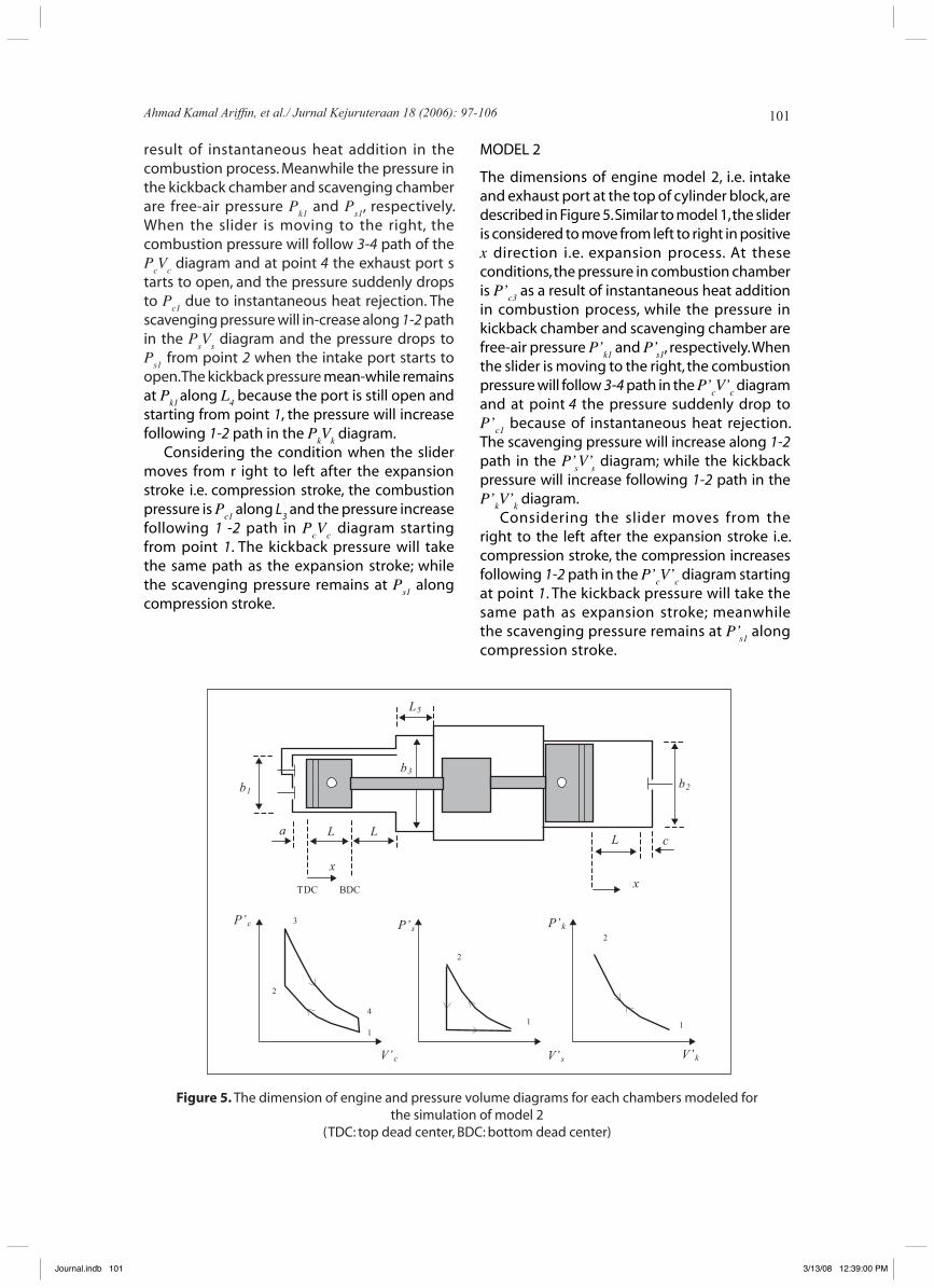
MODEL 2
The dimensions of engine model 2, i.e. intake and exhaust port at the top of cylinder block, are described in Figure 5. Similar to model 1, the slider is considered to move from left to right in positive x direction i.e. expansion process. At these conditions, the pressure in combustion chamber is P’c3 as a result of instantaneous heat addition in combustion process, while the pressure in kickback chamber and scavenging chamber are free-air pressure P’k1 and P’s1, respectively. When the slider is moving to the right, the combustion pressure will follow 3-4 path in the P’cV’c diagram and at point 4 the pressure suddenly drop to P’c1 because of instantaneous heat rejection. The scavenging pressure will increase along 1-2 path in the P’sV’s diagram; while the kickback pressure will increase following 1-2 path in the P’kV’k diagram.
Considering the slider moves from the right to the left after the expansion stroke i.e. compression stroke, the compression increases following 1-2 path in the P’cV’c diagram starting at point 1. The kickback pressure will take the same path as expansion stroke; meanwhile the scavenging pressure remains at P’s1 along compression stroke.
Figure 5. The dimension of engine and pressure volume diagrams for each chambers modeled for the simulation of model 2
(TDC: top dead center, BDC: bottom dead center)
b1b2
b3
x x
a L L L
L5
c
TDC BDC
P’c
V’c
1
2
3
4
P’k
V’k
1
2P’s
V’s
1
2
Ahmad Kamal Ariffin, et al./ Jurnal Kejuruteraan 18 (2006): 97-106
Journal.indb 101 3/13/08 12:39:00 PM
102
In order to develop the pressure equations of each chamber, the processes are assumed to obey a polytropic process. The relationship between the pressure and the volume for polytropic process is described by (Heywood 1988):
The interdependence between the three thermodynamic properties pressure (P), volume (V), and temperature (T) is given by the state equation. For ideal gases, the state equation is given by (Heywood 1988):
where P is the gas pressure, V is the gas volume, m is the gas mass, R is the gas constant, and T is the absolute temperature. This is also known as the law of ideal gases.
RESULTS AND DISCUSSION
MODEL 1
The equations that described the pressures of each chambers are derived from equation (4) and/or equation (5). Equations (6) and (7) represent the force balance equations for expansion process and for compression process, respectively, in engine model 1, where Patm is atmospheric pressure, Qin is the heat addition to combustion chamber during combustion process, and n is the specific heat ratio.
MODEL 2
Equations (8) and (9) represent the force balance equations for expansion process and for compression process respectively, in engine model 2. These equations show that compression ratio for model 2 is higher than model 1 since L>L
1 and L>L
2.
(4)
2
2
dt
xdmF ��
constPV n �
mRTPV �
n
atmc
n
c
inn
atm c
cLPA
xa
a
AaL
na
aLQ
a
aLP �
���
�� �
�����
��
����
���
�
���
���
�
�
�����
�� �
�����
�� � 2
1
1
1
)(
)1(
s
n
atmk
n
AxLbLb
LbLbPA
xcLL
c
���
���
���
����
����
���� )2()()(
2)()(2
152
3
215
23
42
2
2
dt
xdmFF ef ���
c
nn
atmk
nn
atm Axa
a
a
aLPA
xcLL
c
c
cLP �
���
��
�����
�� �
����
����
����
����
�� � 1
42
2
2
2
dtxd
mFFAP efsatm ����
n
atmc
n
c
inn
atm c
cLPA
xa
a
AaL
na
aLQ
a
aLP �
��
��� ���
��
���
����
���
�
���
���
�
�
����
��� �
����
��� �
)(
)1(
s
n
atmk
n
AxLbLb
LbLbPA
xcL
c
���
���
�����
��
���
�� )2()()(
2)()(2
152
3
215
23
2
2
dt
xdmFF ef ���
c
nn
atmk
nn
atm Axa
aaaL
PAxcL
cccL
P ���
���
����
��� ���
��
���
�����
��� �
2
2
dtxd
mFFAP efsatm ����
2
2
dt
xdmF ��
constPV n �
mRTPV �
n
atmc
n
c
inn
atm c
cLPA
xa
a
AaL
na
aLQ
a
aLP �
���
�� �
�����
��
����
���
�
���
���
�
�
�����
�� �
�����
�� � 2
1
1
1
)(
)1(
s
n
atmk
n
AxLbLb
LbLbPA
xcLL
c
���
���
���
����
����
���� )2()()(
2)()(2
152
3
215
23
42
2
2
dt
xdmFF ef ���
c
nn
atmk
nn
atm Axa
a
a
aLPA
xcLL
c
c
cLP �
���
��
�����
�� �
����
����
����
����
�� � 1
42
2
2
2
dtxd
mFFAP efsatm ����
n
atmc
n
c
inn
atm c
cLPA
xa
a
AaL
na
aLQ
a
aLP �
��
��� ���
��
���
����
���
�
���
���
�
�
����
��� �
����
��� �
)(
)1(
s
n
atmk
n
AxLbLb
LbLbPA
xcL
c
���
���
�����
��
���
�� )2()()(
2)()(2
152
3
215
23
2
2
dt
xdmFF ef ���
c
nn
atmk
nn
atm Axa
aaaL
PAxcL
cccL
P ���
���
����
��� ���
��
���
�����
��� �
2
2
dtxd
mFFAP efsatm ����
(5)
2
2
dt
xdmF ��
constPV n �
mRTPV �
n
atmc
n
c
inn
atm c
cLPA
xa
a
AaL
na
aLQ
a
aLP �
���
�� �
�����
��
����
���
�
���
���
�
�
�����
�� �
�����
�� � 2
1
1
1
)(
)1(
s
n
atmk
n
AxLbLb
LbLbPA
xcLL
c
���
���
���
����
����
���� )2()()(
2)()(2
152
3
215
23
42
2
2
dt
xdmFF ef ���
c
nn
atmk
nn
atm Axa
a
a
aLPA
xcLL
c
c
cLP �
���
��
�����
�� �
����
����
����
����
�� � 1
42
2
2
2
dtxd
mFFAP efsatm ����
n
atmc
n
c
inn
atm c
cLPA
xa
a
AaL
na
aLQ
a
aLP �
��
��� ���
��
���
����
���
�
���
���
�
�
����
��� �
����
��� �
)(
)1(
s
n
atmk
n
AxLbLb
LbLbPA
xcL
c
���
���
�����
��
���
�� )2()()(
2)()(2
152
3
215
23
2
2
dt
xdmFF ef ���
c
nn
atmk
nn
atm Axa
aaaL
PAxcL
cccL
P ���
���
����
��� ���
��
���
�����
��� �
2
2
dtxd
mFFAP efsatm ����
2
2
dt
xdmF ��
constPV n �
mRTPV �
n
atmc
n
c
inn
atm c
cLPA
xa
a
AaL
na
aLQ
a
aLP �
���
�� �
�����
��
����
���
�
���
���
�
�
�����
�� �
�����
�� � 2
1
1
1
)(
)1(
s
n
atmk
n
AxLbLb
LbLbPA
xcLL
c
���
���
���
����
����
���� )2()()(
2)()(2
152
3
215
23
42
2
2
dt
xdmFF ef ���
c
nn
atmk
nn
atm Axa
a
a
aLPA
xcLL
c
c
cLP �
���
��
�����
�� �
����
����
����
����
�� � 1
42
2
2
2
dtxd
mFFAP efsatm ����
n
atmc
n
c
inn
atm c
cLPA
xa
a
AaL
na
aLQ
a
aLP �
��
��� ���
��
���
����
���
�
���
���
�
�
����
��� �
����
��� �
)(
)1(
s
n
atmk
n
AxLbLb
LbLbPA
xcL
c
���
���
�����
��
���
�� )2()()(
2)()(2
152
3
215
23
2
2
dt
xdmFF ef ���
c
nn
atmk
nn
atm Axa
aaaL
PAxcL
cccL
P ���
���
����
��� ���
��
���
�����
��� �
2
2
dtxd
mFFAP efsatm ����
(7)
2
2
dt
xdmF ��
constPV n �
mRTPV �
n
atmc
n
c
inn
atm c
cLPA
xa
a
AaL
na
aLQ
a
aLP �
���
�� �
�����
��
����
���
�
���
���
�
�
�����
�� �
�����
�� � 2
1
1
1
)(
)1(
s
n
atmk
n
AxLbLb
LbLbPA
xcLL
c
���
���
���
����
����
���� )2()()(
2)()(2
152
3
215
23
42
2
2
dt
xdmFF ef ���
c
nn
atmk
nn
atm Axa
a
a
aLPA
xcLL
c
c
cLP �
���
��
�����
�� �
����
����
����
����
�� � 1
42
2
2
2
dtxd
mFFAP efsatm ����
n
atmc
n
c
inn
atm c
cLPA
xa
a
AaL
na
aLQ
a
aLP �
��
��� ���
��
���
����
���
�
���
���
�
�
����
��� �
����
��� �
)(
)1(
s
n
atmk
n
AxLbLb
LbLbPA
xcL
c
���
���
�����
��
���
�� )2()()(
2)()(2
152
3
215
23
2
2
dt
xdmFF ef ���
c
nn
atmk
nn
atm Axa
aaaL
PAxcL
cccL
P ���
���
����
��� ���
��
���
�����
��� �
2
2
dtxd
mFFAP efsatm ����
2
2
dt
xdmF ��
constPV n �
mRTPV �
n
atmc
n
c
inn
atm c
cLPA
xa
a
AaL
na
aLQ
a
aLP �
���
�� �
�����
��
����
���
�
���
���
�
�
�����
�� �
�����
�� � 2
1
1
1
)(
)1(
s
n
atmk
n
AxLbLb
LbLbPA
xcLL
c
���
���
���
����
����
���� )2()()(
2)()(2
152
3
215
23
42
2
2
dt
xdmFF ef ���
c
nn
atmk
nn
atm Axa
a
a
aLPA
xcLL
c
c
cLP �
���
��
�����
�� �
����
����
����
����
�� � 1
42
2
2
2
dtxd
mFFAP efsatm ����
n
atmc
n
c
inn
atm c
cLPA
xa
a
AaL
na
aLQ
a
aLP �
��
��� ���
��
���
����
���
�
���
���
�
�
����
��� �
����
��� �
)(
)1(
s
n
atmk
n
AxLbLb
LbLbPA
xcL
c
���
���
�����
��
���
�� )2()()(
2)()(2
152
3
215
23
2
2
dt
xdmFF ef ���
c
nn
atmk
nn
atm Axa
aaaL
PAxcL
cccL
P ���
���
����
��� ���
��
���
�����
��� �
2
2
dtxd
mFFAP efsatm ����
(6)
2
2
dt
xdmF ��
constPV n �
mRTPV �
n
atmc
n
c
inn
atm c
cLPA
xa
a
AaL
na
aLQ
a
aLP �
���
�� �
�����
��
����
���
�
���
���
�
�
�����
�� �
�����
�� � 2
1
1
1
)(
)1(
s
n
atmk
n
AxLbLb
LbLbPA
xcLL
c
���
���
���
����
����
���� )2()()(
2)()(2
152
3
215
23
42
2
2
dt
xdmFF ef ���
c
nn
atmk
nn
atm Axa
a
a
aLPA
xcLL
c
c
cLP �
���
��
�����
�� �
����
����
����
����
�� � 1
42
2
2
2
dtxd
mFFAP efsatm ����
n
atmc
n
c
inn
atm c
cLPA
xa
a
AaL
na
aLQ
a
aLP �
��
��� ���
��
���
����
���
�
���
���
�
�
����
��� �
����
��� �
)(
)1(
s
n
atmk
n
AxLbLb
LbLbPA
xcL
c
���
���
�����
��
���
�� )2()()(
2)()(2
152
3
215
23
2
2
dt
xdmFF ef ���
c
nn
atmk
nn
atm Axa
aaaL
PAxcL
cccL
P ���
���
����
��� ���
��
���
�����
��� �
2
2
dtxd
mFFAP efsatm ����
2
2
dt
xdmF ��
constPV n �
mRTPV �
n
atmc
n
c
inn
atm c
cLPA
xa
a
AaL
na
aLQ
a
aLP �
���
�� �
�����
��
����
���
�
���
���
�
�
�����
�� �
�����
�� � 2
1
1
1
)(
)1(
s
n
atmk
n
AxLbLb
LbLbPA
xcLL
c
���
���
���
����
����
���� )2()()(
2)()(2
152
3
215
23
42
2
2
dt
xdmFF ef ���
c
nn
atmk
nn
atm Axa
a
a
aLPA
xcLL
c
c
cLP �
���
��
�����
�� �
����
����
����
����
�� � 1
42
2
2
2
dtxd
mFFAP efsatm ����
n
atmc
n
c
inn
atm c
cLPA
xa
a
AaL
na
aLQ
a
aLP �
��
��� ���
��
���
����
���
�
���
���
�
�
����
��� �
����
��� �
)(
)1(
s
n
atmk
n
AxLbLb
LbLbPA
xcL
c
���
���
�����
��
���
�� )2()()(
2)()(2
152
3
215
23
2
2
dt
xdmFF ef ���
c
nn
atmk
nn
atm Axa
aaaL
PAxcL
cccL
P ���
���
����
��� ���
��
���
�����
��� �
2
2
dtxd
mFFAP efsatm ����
(8)
2
2
dt
xdmF ��
constPV n �
mRTPV �
n
atmc
n
c
inn
atm c
cLPA
xa
a
AaL
na
aLQ
a
aLP �
���
�� �
�����
��
����
���
�
���
���
�
�
�����
�� �
�����
�� � 2
1
1
1
)(
)1(
s
n
atmk
n
AxLbLb
LbLbPA
xcLL
c
���
���
���
����
����
���� )2()()(
2)()(2
152
3
215
23
42
2
2
dt
xdmFF ef ���
c
nn
atmk
nn
atm Axa
a
a
aLPA
xcLL
c
c
cLP �
���
��
�����
�� �
����
����
����
����
�� � 1
42
2
2
2
dtxd
mFFAP efsatm ����
n
atmc
n
c
inn
atm c
cLPA
xa
a
AaL
na
aLQ
a
aLP �
��
��� ���
��
���
����
���
�
���
���
�
�
����
��� �
����
��� �
)(
)1(
s
n
atmk
n
AxLbLb
LbLbPA
xcL
c
���
���
�����
��
���
�� )2()()(
2)()(2
152
3
215
23
2
2
dt
xdmFF ef ���
c
nn
atmk
nn
atm Axa
aaaL
PAxcL
cccL
P ���
���
����
��� ���
��
���
�����
��� �
2
2
dtxd
mFFAP efsatm ����
Ahmad Kamal Ariffin, et al./ Jurnal Kejuruteraan 18 (2006): 97-106
Journal.indb 102 3/13/08 12:39:04 PM
103
Table 1. Simulated engine specifications
2
2
dt
xdmF ��
constPV n �
mRTPV �
n
atmc
n
c
inn
atm c
cLPA
xa
a
AaL
na
aLQ
a
aLP �
���
�� �
�����
��
����
���
�
���
���
�
�
�����
�� �
�����
�� � 2
1
1
1
)(
)1(
s
n
atmk
n
AxLbLb
LbLbPA
xcLL
c
���
���
���
����
����
���� )2()()(
2)()(2
152
3
215
23
42
2
2
dt
xdmFF ef ���
c
nn
atmk
nn
atm Axa
a
a
aLPA
xcLL
c
c
cLP �
���
��
�����
�� �
����
����
����
����
�� � 1
42
2
2
2
dtxd
mFFAP efsatm ����
n
atmc
n
c
inn
atm c
cLPA
xa
a
AaL
na
aLQ
a
aLP �
��
��� ���
��
���
����
���
�
���
���
�
�
����
��� �
����
��� �
)(
)1(
s
n
atmk
n
AxLbLb
LbLbPA
xcL
c
���
���
�����
��
���
�� )2()()(
2)()(2
152
3
215
23
2
2
dt
xdmFF ef ���
c
nn
atmk
nn
atm Axa
aaaL
PAxcL
cccL
P ���
���
����
��� ���
��
���
�����
��� �
2
2
dtxd
mFFAP efsatm ����
2
2
dt
xdmF ��
constPV n �
mRTPV �
n
atmc
n
c
inn
atm c
cLPA
xa
a
AaL
na
aLQ
a
aLP �
���
�� �
�����
��
����
���
�
���
���
�
�
�����
�� �
�����
�� � 2
1
1
1
)(
)1(
s
n
atmk
n
AxLbLb
LbLbPA
xcLL
c
���
���
���
����
����
���� )2()()(
2)()(2
152
3
215
23
42
2
2
dt
xdmFF ef ���
c
nn
atmk
nn
atm Axa
a
a
aLPA
xcLL
c
c
cLP �
���
��
�����
�� �
����
����
����
����
�� � 1
42
2
2
2
dtxd
mFFAP efsatm ����
n
atmc
n
c
inn
atm c
cLPA
xa
a
AaL
na
aLQ
a
aLP �
��
��� ���
��
���
����
���
�
���
���
�
�
����
��� �
����
��� �
)(
)1(
s
n
atmk
n
AxLbLb
LbLbPA
xcL
c
���
���
�����
��
���
�� )2()()(
2)()(2
152
3
215
23
2
2
dt
xdmFF ef ���
c
nn
atmk
nn
atm Axa
aaaL
PAxcL
cccL
P ���
���
����
��� ���
��
���
�����
��� �
2
2
dtxd
mFFAP efsatm ���� (9)
Parameter Model 1 Model 2
Effective combustion stroke 0.04 m (L1) 0.07 m (L)
Effective kickback stroke 0.055 m (L2) 0.07 m (L)
Exhaust length (L3) 0.03 m 0.03 m
Intake length (L4) 0.015 m 0.015 m
Back-scavenging length (L5) 0.05 m 0.05 m
Specific heat ratio (n) 1.4 1.4
Mass of slider (m) 4.6 kg 4.6 kg
Free air pressure (P1) 100 kPa 100 kPa
Combustion crevice length (a) 0.004 m 0.004 m
Kickback crevice length (c) 0.006 m 0.006 m
Combustion bore diameter (b1) 0.076 m 0.076 m
Kickback bore diameter (b2) 0.11 m 0.11 m
Back-scavenging diameter (b3) 0.114 m 0.114 m
Heat addition (Qin) 300 J 300 J
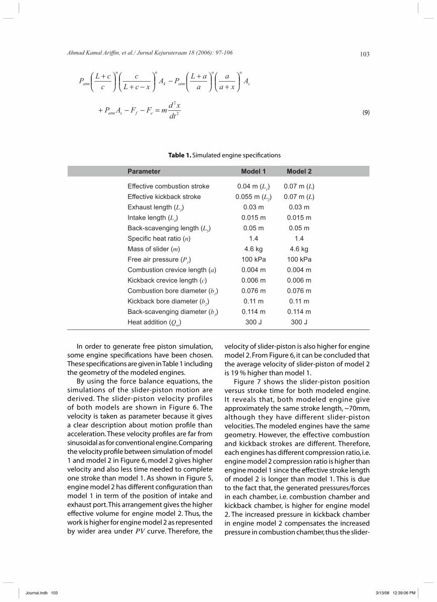
In order to generate free piston simulation, some engine specifications have been chosen. These specifications are given in Table 1 including the geometry of the modeled engines.
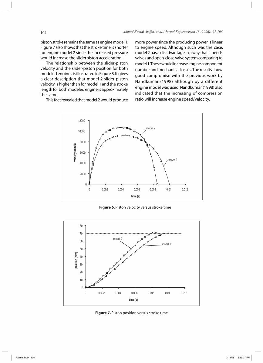
By using the force balance equations, the simulations of the slider-piston motion are derived. The slider-piston velocity profiles of both models are shown in Figure 6. The velocity is taken as parameter because it gives a clear description about motion profile than acceleration. These velocity profiles are far from sinusoidal as for conventional engine. Comparing the velocity profile between simulation of model 1 and model 2 in Figure 6, model 2 gives higher velocity and also less time needed to complete one stroke than model 1. As shown in Figure 5, engine model 2 has different configuration than model 1 in term of the position of intake and exhaust port. This arrangement gives the higher effective volume for engine model 2. Thus, the work is higher for engine model 2 as represented by wider area under PV curve. Therefore, the
velocity of slider-piston is also higher for engine model 2. From Figure 6, it can be concluded that the average velocity of slider-piston of model 2 is 19 % higher than model 1.
Figure 7 shows the slider-piston position versus stroke time for both modeled engine. It reveals that, both modeled engine give approximately the same stroke length, ~70mm, although they have different slider-piston velocities. The modeled engines have the same geometry. However, the effective combustion and kickback strokes are different. Therefore, each engines has different compression ratio, i.e. engine model 2 compression ratio is higher than engine model 1 since the effective stroke length of model 2 is longer than model 1. This is due to the fact that, the generated pressures/forces in each chamber, i.e. combustion chamber and kickback chamber, is higher for engine model 2. The increased pressure in kickback chamber in engine model 2 compensates the increased pressure in combustion chamber, thus the slider-
Ahmad Kamal Ariffin, et al./ Jurnal Kejuruteraan 18 (2006): 97-106
Journal.indb 103 3/13/08 12:39:06 PM
104
Figure 7. Piston position versus stroke time
10
20
30
40
50
60
70
80
0 0.002 0.004 0.006 0.008 0.01 0.012
time (s)
model 1
model 2
posi
tion
(mm
)
piston stroke remains the same as engine model 1. Figure 7 also shows that the stroke time is shorter for engine model 2 since the increased pressure would increase the sliderpiston acceleration.
The relationship between the slider-piston velocity and the slider-piston position for both modeled engines is illustrated in Figure 8. It gives a clear description that model 2 slider-piston velocity is higher than for model 1 and the stroke length for both modeled engine is approximately the same.
This fact revealed that model 2 would produce
Figure 6. Piston velocity versus stroke time
0
2000
4000
6000
8000
10000
12000
0 0.002 0.004 0.006 0.008 0.01 0.012
time (s)
model 2
model 1velo
city
(mm
/s)
more power since the producing power is linear to engine speed. Although such was the case, model 2 has a disadvantage in a way that it needs valves and open-close valve system comparing to model 1. These would increase engine component number and mechanical losses. The results show good compromise with the previous work by Nandkumar (1998) although by a different engine model was used. Nandkumar (1998) also indicated that the increasing of compression ratio will increase engine speed/velocity.
Ahmad Kamal Ariffin, et al./ Jurnal Kejuruteraan 18 (2006): 97-106
Journal.indb 104 3/13/08 12:39:07 PM

105
CONCLUSIONS
Dynamic and gas-dynamic model of free piston linear engine have been presented in this paper. The velocity and displacement profiles of slider-piston motion with respect to time are investigated for different modeled engines. The slider-piston motion of two-stroke free piston linear engine was successfully simulated. By comparing the results between engine model 1 and model 2, it revealed that the slider-piston velocity for the engines are not similar
in completing one stroke, even for the same-modeled engine geometry. Slider-piston velocity of model 2 is 19 % higher than model 1. However, model 1 does not need valves and open-close valves system as for model 2.
ACKNOWLEDGMENTS
The project was financed by Malaysian Ministry of Science, Technology, and Innovation under IRPA project 03-02-02-0056 PR0025/04-03.
Figure 8. Piston velocity versus piston position
model 1
model 2
0
2000
4000
6000
8000
10000
12000
0 20 40 60 80
position (mm)
velo
city
(mm
/s)
TERMINOLOGY
Symbol Description Units Symbol Description Units
A Area m2 Qin Heat addition J b Diameter m R Gas constant kJ/(kmol.K)
F Force N T Temperature K m mass kg t Time s n Specific heat ratio - V Volume m3
P Pressure Pa x Displacement m
Ahmad Kamal Ariffin, et al./ Jurnal Kejuruteraan 18 (2006): 97-106
Journal.indb 105 3/13/08 12:39:07 PM

106
REFERENCES
Aichlmayr, H.T., Kittelson, D.B. & Zachariah, M.R. 2002. Miniature Free-Piston Homogeneous Charge Compression Ignition Engine-Compressor Concept Part I: Performance Estimation and Design Considerations Unique to Small Dimensions. Chemical Engineering Science 57 :4161-4171.
Annen, K.D., Stickler D.B. & Woodroffe J. 2002. Miniature Internal Combustion Engine (MICE) for Portable Electric Power, Aerodyne Research. Inc. Proceeding of 23rd Army Science Conference. Florida.
Arshad W.M., Bäckström T., Thelin P., and Sadarangani C. 2002. Integrated Free-Piston Generator: an Overview. Proceeding of NORPIE/2002. Stockholm. Sweden.
Atkinson, C.M., Petreanu, S., Clark, N.N., Atkinson, R.J., McDaniel, T.I., Nandkumar, S. &Famouri, P. 1999. Numerical Simulation of Two-Stroke Linear Engine-Alternator Combination. SAE Paper 1999-01-0921.
Fonna, S., Mohamed, N.A.N. & Ariffin, A.K. 2004. Simulation Including Intake and Exhaust Port Effects of Two-stroke Free Piston Linear Generator Engine Motion. Proceedings Seminar Computational Mechanics & Numerical Analysis. pp. 57-62. June 5th. Banda Aceh.
Goldsborough, S.S. &Van Blarigan, P. 1999. A Numerical Study of a Free Piston IC Operating on Homogeneous Charge Compression Ignition Combustion. SAE Paper 1999-01-0619.
Heywood, J.B. 1988. Internal Combustion Engine Fundamentals. Singapore: McGraw-Hill Book Company.
Houdyschell, D. 2000. A Diesel Two-stroke Linear Engine. Master of Science Thesis. West Virginia University: Morgantown. West Virginia.
Nandkumar, S. 1998. Two-Stroke Linear Engine. Master of Science Thesis. West Virginia University: Morgantown. West Virginia.
Ahmad Kamal Ariffin, et al./ Jurnal Kejuruteraan 18 (2006): 97-106
Journal.indb 106 3/13/08 12:39:08 PM