Embed Size (px)
Citation preview
Department of Electrical Engineering Sharif University of Technology
Data Networks Dr. M. R. Pakravan 1
Simulation of LAN Parts
Ethernet (Aloha, CSMA-CD), Wireless LAN
Goals
1) To understand the Aloha, CSMA and 802.3 protocols as well as CSMA/CA protocol in 82.11 and RTS/CTS function and see how a LAN shares its workspace.
2) To perform simulations in OPNET which incorporate the Aloha random channel access method and the 1-persistent CSMA method on a multi-tap bus link, where multiple nodes are connected through a shared channel. Each method’s performance will be compared against the others.
3) To evaluate the behavior of IEEE 802.3 protocol and analyze delay, jitter and throughput of a nominal LAN versus its load.
4) To become familiar with “wlan_station_adv” node, basic procedures to design and simulate a simple infrastructure WLAN network and collecting and viewing simple performance figures such as throughput and delay.
5) To understand the effects of hidden node and packet fragmentation on the delay, collision and throughput of a channel.
Part 1: Introduction
The MAC (Medium Access) is a sub-layer of data link layer and it mainly deals with protocols that are used to share the resources and determine who could use them next on a multi access channel. The simplest algorithm in MAC layer is pure ALOHA. In this protocol, stations transmit whenever they have something to send and then listen to channel to find out whether any frames are destroyed by collision, then retransmit those frames. The next version is slotted ALOHA at which the time is divided up into discrete intervals and stations are allowed to send only at the beginning of each slot. As you know the efficiency of slotted ALOHA is twice the pure ALOHA.
Department of Electrical Engineering Sharif University of Technology
Data Networks Dr. M. R. Pakravan 2
To improve the efficiency of the MAC layer a carrier sense protocol can be used to reduce the number of packets that are lost due to collision. Using this approach, when a station has something to send it first listens to channel to make sure that nobody else is transmitting at the moment. If the channel is idle, it begins transmitting its packets, if not, the station waits until the channel becomes free. This protocol is called “1-persistent CSMA”. Another carrier sense protocol is “non persistent CSMA”. In this protocol, stations sense the channel and begin transmitting if the channel is detected to be free as in “1-persistent CSMA”. However, if the channel is busy, the station does not continually sense it but waits a random amount of time and then senses the channel again. The third carrier sense protocol is “p-persistent CSMA” that is used for slotted channels. In this protocol even if the channel is sensed to be idle, the transmission is done with the probability p. It’s obvious that non-persistent CSMA has the best efficiency, but it can have a large delay in processing packets and sending them. The most widely used protocol in MAC layer is CSMA/CD that is an improved version of CSMA because stations abruptly stop transmitting when they detect collision and avoid the waste that is caused by transmitting the remaining bytes of a destroyed frame. Ethernet, which is the most dominant LAN protocol, uses 1-persistent CSMA/CD protocol that is standardized by IEEE as 802.3. In this experiment, we want to simulate Aloha, CSMA and 802.3 protocols. The goal of this Lab is to observe how the performance of these protocols varies as a function of channel traffic.
Where to start?
For the simulation of ALOHA and CSMA protocol you should first add the directory of this models to OPNET model directories. The directory path of the models depends on the OPNET install directory. For example if OPNET is installed in “C:\Program Files\OPNET””, it will be “C:\Program Files\OPNET\14.5.A\models\tutorial_ref\modeler”
Select File ⇒ Manage Model Files ⇒ select Add Model Directory, and Then go to above directory ⇒ Click OK.
OPNET has a sample project related to ALOHA and CSMA. The project name is cct_ref. There are two pre-built simulation scenarios in this project. You can use these samples as a guide to help you through the rest of the Lab. You can also refer to the OPNET Documentation for further help on this project. There is another project named ethcoax_net_ref that can give you hints on how to simulate LANs. You can refer to this project and its documentation for further information.
Create a new project
The first step in the Lab is to create a new project in OPNET: 1. Start OPNET Modeler⇒ Choose New from the File menu.
Department of Electrical Engineering Sharif University of Technology
Data Networks Dr. M. R. Pakravan 3
2. Select Project ⇒ Click OK ⇒ Name the project <your_initials>_MAC ⇒ Click OK. 3. In the Startup Wizard: Initial Topology dialog box, make sure that Create Empty Scenario is selected ⇒ Click Next ⇒ Choose Office from the Network Scale list ⇒ Click Next ⇒ Choose a proper size for the network⇒ Click Next 4. Choose ethcoax among objects and click Next. The project is created and the object palette is opened where you should add the link and node models that you want through the rest of the project. Add cct_rx_ref, cct_tx_ref and cct_csma_tx_ref Node models and cct_link_ref link model to the palette. 1. Click on the Node Models button, and then add cct_tx_ref, cct_rx_ref and cct_csma_tx_ref from the list of available node models. 2. Click on the Link Models button, and then add cct_link_ref from the list of available link models. 3. Close the object palette. You can access it when needed via the leftmost icon on the toolbar. .
Topology Configuration
In the first scenario, we want to simulate a network with nodes using ALOHA to access the shared bus. To perform such simulation, we should create a bus topology with a number of nodes. Instead of creating the entire bus network by hand, you can use rapid configuration to build it quickly: 1) Choose Rapid Configuration from the Topology menu. 2) Select Bus from the menu of available configuration, and then click OK. 3) In the Rapid Configuration: Bus dialog box, set the node model to cct_tx_ref and link model and tap model to cct_link_ref and number of nodes to 25. 4) Click OK when all the values are entered Now you should add a receiver to the bus. To add this node and connect it to the network: 1) Click and drag the receiver node cct_rx_ref from the Object Palette into the left side of the tool area. 2) Click on the cct_link_ref tap link in the palette, and then draw a tap from the bus to the receiver node.
ALOHA simulation
Configure a network of 25 nodes running ALOHA protocol. Select Configure/Run Discrete Event Simulation from the DES menu and refer to OPNET Documentation to learn how to run a set of simulations using this tool. Add max_packet_count and packet inter-arrival time to the simulation attributes. (Hint: Input ⇒ Global Attributes and Object Attributes) max_packet_count is the number of packets exchanged until the end of the simulation. Choose a typical value such as 2000 for it. Choose multiple values for the inter-arrival time and run the simulation. The results
Department of Electrical Engineering Sharif University of Technology
Data Networks Dr. M. R. Pakravan 4
of each simulation are stored as two scalar values in the output scalar file, allowing you to view the network’s performance as a function of an input parameter rather than a function of time. Now the only remaining task is to create a plot of the results. Choose DES ⇒ Results ⇒ View Results Draw a plot of Channel throughput versus channel traffic in this editor environment. Refer to OPNET help to learn how to create a graph of two scalars in this editor. This Plot shows the performance of the ALOHA network.
CSMA simulation
In this part, we want to find the performance of a 1-persistant CSMA network. To do this, follow these steps: Create a new scenario: Choose Scenario ⇒New scenario Repeat the previously mentioned procedure to build a CSMA network. The only difference is in the Rapid Topology Configuration where you should choose cct_csma_tx_ref for the node models. Run a series of simulations to find a plot of network throughput versus channel traffic for CSMA network. Compare the performance of CSMA with ALOHA.
802.3 simulation
In this part, you will set up an Ethernet with some nodes connected via a coaxial link in a bus Topology. The coaxial link is operating at a data rate of 10 Mbps. You will study how the Throughput of the network is affected by the network load as well as the size of the Packets. Create a new scenario in your project. Use rapid configuration to create a bus topology of 15 nodes. Use ethcoax_station as Node Model, ethcoax as Link model and eth_tap as tap model. Change the traffic generation attribute of the Ethernet workstations to a proper value. Right click on the station ⇒Edit attributes ⇒ Traffic generation parameters ⇒Edit Choose the bus utilization as a static to be collected during simulation: DES ⇒Choose Individual statistics ⇒ Link Statistics ⇒ Bus ⇒ Utilization Run the simulation and observe the results:
Department of Electrical Engineering Sharif University of Technology
Data Networks Dr. M. R. Pakravan 5
DES ⇒ Results ⇒ View Results Find the time_average value of the link utilization as a performance measure for CSMA network. Run the simulation for various loads and find the utilization of the Ethernet network. Compare it with the case of ALOHA and CSMA. Also run the simulation for proper values of packet size and study the effect of packet size on utilization. By segmenting the packets in proper size, consider the effect of segmentation on the performance of protocol.
Part 2: Introduction
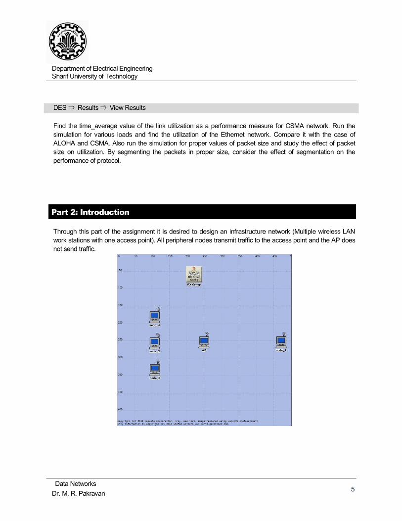
Through this part of the assignment it is desired to design an infrastructure network (Multiple wireless LAN work stations with one access point). All peripheral nodes transmit traffic to the access point and the AP does not send traffic.
Department of Electrical Engineering Sharif University of Technology
Data Networks Dr. M. R. Pakravan 6
RTC/CTS and Hidden node Simulation
In this part we will investigate the Hidden node Problem and how RTS/CTS function intends to prevent collisions. Our sample network consists of one access point surrounded by four wireless stations (laptops). This network employs either CSMA/CA or RTS/CTS access.
Project Creation Steps
• From the project editor window, open a new project. Note: Make sure that you have saved your project under the name “<Your Initials>_Wireless” and the scenario name “1_No_Hidden_nodes_without_RTS_CTS” • From the “Startup Wizard: Initial Topology” window, select “Create empty scenario”. • From the “Startup Wizard: Choose Network Scale” window select “Office Scale”. • In the “Startup Wizard: Specify Size” window select 500 for both “X span” and “Y span”. Make sure the unit is set to “Meters”. • From the “Startup Wizard: Select Technologies” window include “wireless_lan” and “wireless_lan_adv”. • End the startup wizard by pressing “Finish”. OPNET opens an “Object Palette Tree” window where all built in nodes and links for the technologies of interest are listed.
Customizing Node Behavior
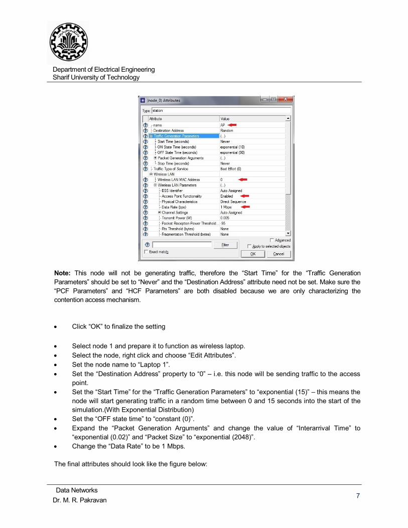
From the “Object Palette Tree” select the “wlan_station_adv” node and place two copies in the project editor window. (Note OPNET gives sequential names for two nodes: node 0 and node 1) (To end the placing of node – right click the mouse) Now we will customize node 0 to behave as an access point while node 1 will be customized to behave as a regular laptop transmitting traffic to the access point. • Select node 0 and prepare it to function as an access point • Select the node, right click and choose “Edit Attributes” • Set the node name to “AP” Set the “Wireless LAN MAC Address” property to “0” • Enable the “Access Point Functionality” property. • Change the “Data Rate” to be 1 Mbps. The final attributes should look like the figure below
Department of Electrical Engineering Sharif University of Technology
Data Networks Dr. M. R. Pakravan 7
Note: This node will not be generating traffic, therefore the “Start Time” for the “Traffic Generation Parameters” should be set to “Never” and the “Destination Address” attribute need not be set. Make sure the “PCF Parameters” and “HCF Parameters” are both disabled because we are only characterizing the contention access mechanism. • Click “OK” to finalize the setting
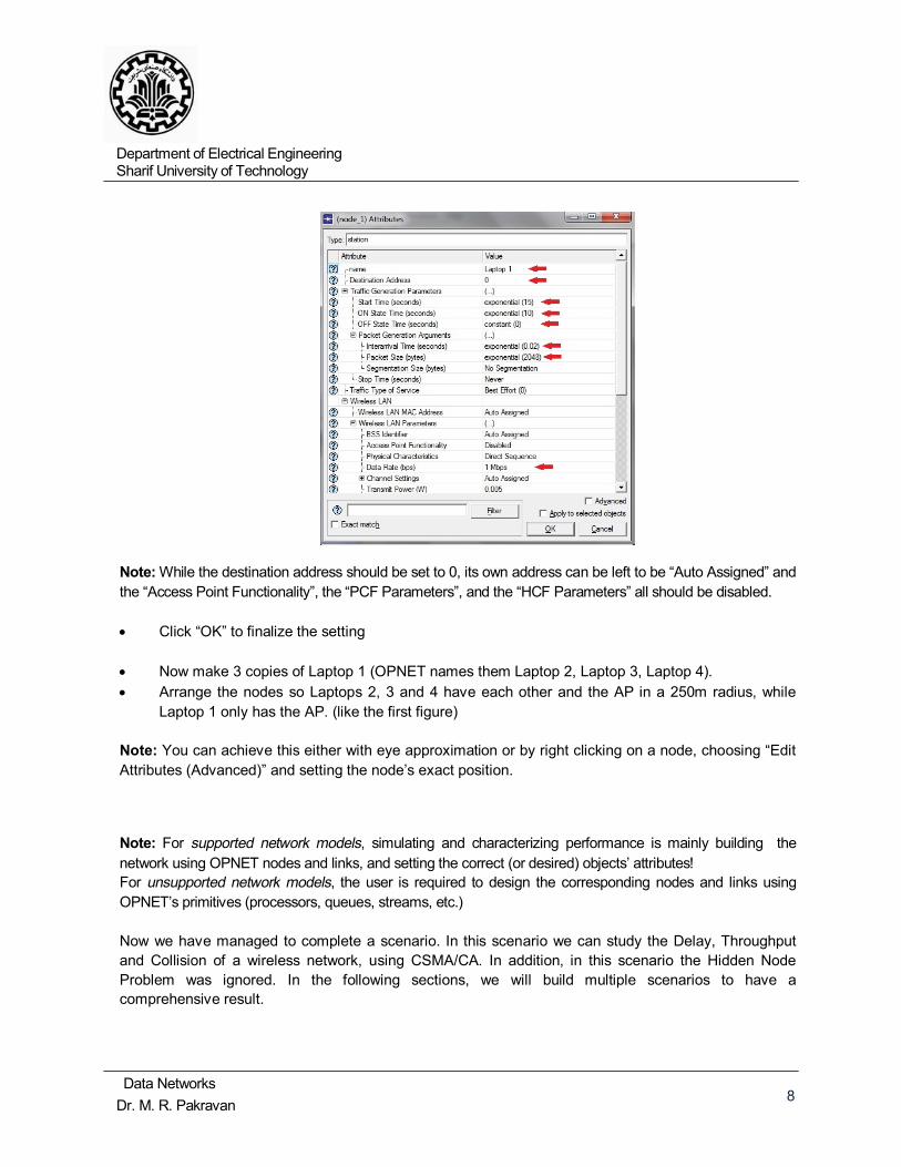
• Select node 1 and prepare it to function as wireless laptop. • Select the node, right click and choose “Edit Attributes”. • Set the node name to “Laptop 1”. • Set the “Destination Address” property to “0” – i.e. this node will be sending traffic to the access point. • Set the “Start Time” for the “Traffic Generation Parameters” to “exponential (15)” – this means the node will start generating traffic in a random time between 0 and 15 seconds into the start of the simulation.(With Exponential Distribution) • Set the “OFF state time” to “constant (0)”. • Expand the “Packet Generation Arguments” and change the value of “Interarrival Time” to “exponential (0.02)” and “Packet Size” to “exponential (2048)”. • Change the “Data Rate” to be 1 Mbps. The final attributes should look like the figure below:
Department of Electrical Engineering Sharif University of Technology
Data Networks Dr. M. R. Pakravan 8
Note: While the destination address should be set to 0, its own address can be left to be “Auto Assigned” and the “Access Point Functionality”, the “PCF Parameters”, and the “HCF Parameters” all should be disabled. • Click “OK” to finalize the setting • Now make 3 copies of Laptop 1 (OPNET names them Laptop 2, Laptop 3, Laptop 4). • Arrange the nodes so Laptops 2, 3 and 4 have each other and the AP in a 250m radius, while Laptop 1 only has the AP. (like the first figure) Note: You can achieve this either with eye approximation or by right clicking on a node, choosing “Edit Attributes (Advanced)” and setting the node’s exact position.
Note: For supported network models, simulating and characterizing performance is mainly building the network using OPNET nodes and links, and setting the correct (or desired) objects’ attributes! For unsupported network models, the user is required to design the corresponding nodes and links using OPNET’s primitives (processors, queues, streams, etc.) Now we have managed to complete a scenario. In this scenario we can study the Delay, Throughput and Collision of a wireless network, using CSMA/CA. In addition, in this scenario the Hidden Node Problem was ignored. In the following sections, we will build multiple scenarios to have a comprehensive result.
Department of Electrical Engineering Sharif University of Technology
Data Networks Dr. M. R. Pakravan 9
Selecting Performance Figures
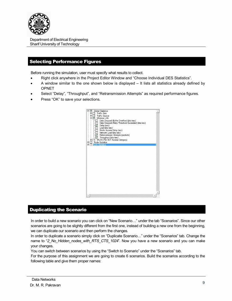
Before running the simulation, user must specify what results to collect. • Right click anywhere in the Project Editor Window and “Choose Individual DES Statistics”. • A window similar to the one shown below is displayed – It lists all statistics already defined by OPNET • Select “Delay”, “Throughput”, and “Retransmission Attempts” as required performance figures. • Press “OK” to save your selections.
Duplicating the Scenario
In order to build a new scenario you can click on “New Scenario…” under the tab “Scenarios”. Since our other scenarios are going to be slightly different from the first one, instead of building a new one from the beginning, we can duplicate our scenario and then perform the changes. In order to duplicate a scenario simply click on “Duplicate Scenario…” under the “Scenarios” tab. Change the name to “2_No_Hidden_nodes_with_RTS_CTS_1024”. Now you have a new scenario and you can make your changes. You can switch between scenarios by using the “Switch to Scenario” under the “Scenarios” tab. For the purpose of this assignment we are going to create 6 scenarios. Build the scenarios according to the following table and give them proper names:
Department of Electrical Engineering Sharif University of Technology
Data Networks Dr. M. R. Pakravan 10
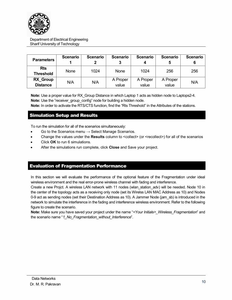
Parameters Scenario 1
Scenario 2
Scenario 3
Scenario 4
Scenario 5
Scenario 6
Rts Threshold None 1024 None 1024 256 256
RX_Group Distance N/A N/A A Proper
value A Proper
value A Proper
value N/A
Note: Use a proper value for RX_Group Distance in which Laptop 1 acts as hidden node to Laptops2-4. Note: Use the ”receiver_group_config” node for building a hidden node. Note: In order to activate the RTS/CTS function, find the “Rts Threshold” in the Attributes of the stations.
Simulation Setup and Results
To run the simulation for all of the scenarios simultaneously: • Go to the Scenarios menu → Select Manage Scenarios. • Change the values under the Results column to <collect> (or <recollect>) for all of the scenarios • Click OK to run 6 simulations. • After the simulations run complete, click Close and Save your project.
Evaluation of Fragmentation Performance
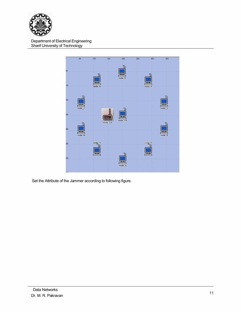
In this section we will evaluate the performance of the optional feature of the Fragmentation under ideal wireless environment and the real error-prone wireless channel with fading and interference. Create a new Projct. A wireless LAN network with 11 nodes (wlan_station_adv) will be needed. Node 10 in the center of the topology acts as a receiving only node (set its Wirelss LAN MAC Address as 10) and Nodes 0-9 act as sending nodes (set their Destination Address as 10). A Jammer Node (jam_sb) is introduced in the network to simulate the interference in the fading and interference wireless environment. Refer to the following figure to create the scenario. Note: Make sure you have saved your project under the name “<Your Initials>_Wireless_Fragmentation” and the scenario name “1_No_Fragmentation_without_Interference”.
Department of Electrical Engineering Sharif University of Technology
Data Networks Dr. M. R. Pakravan 11
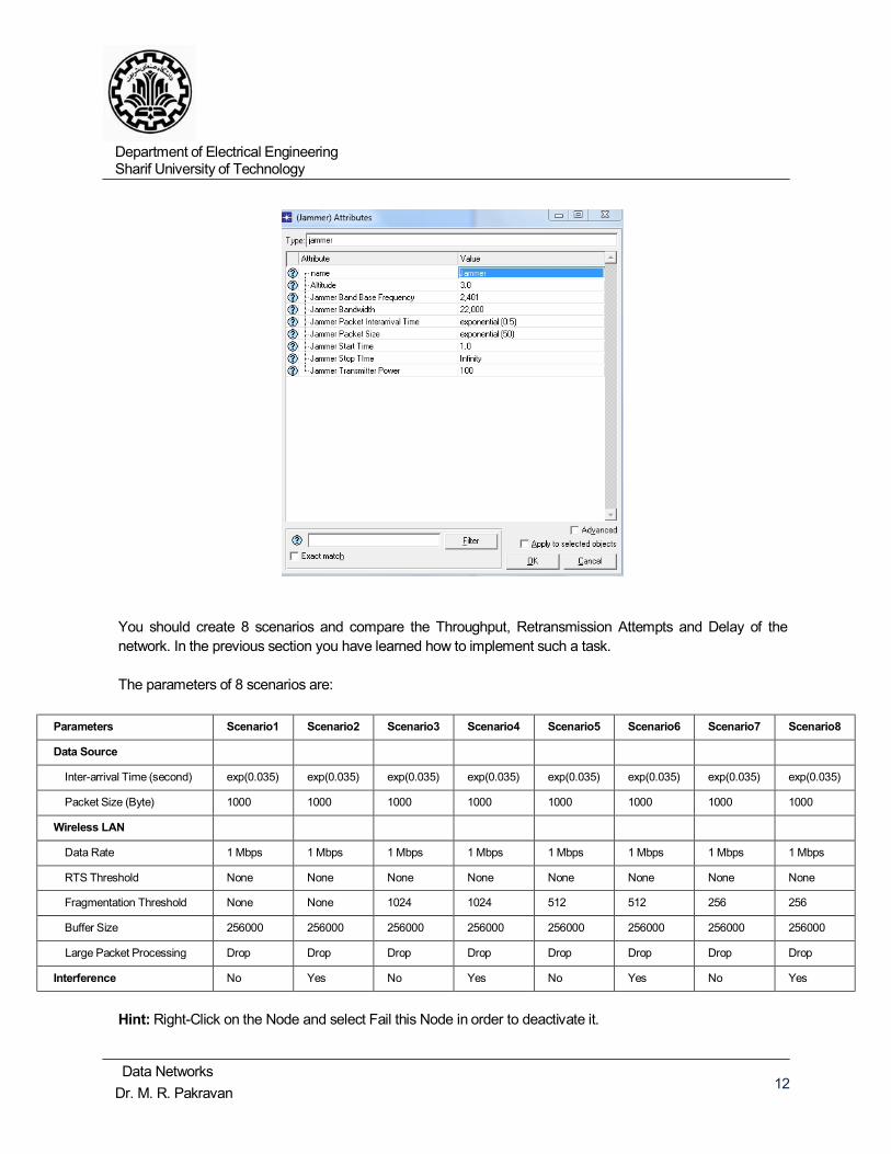
Set the Attribute of the Jammer according to following figure.
Department of Electrical Engineering Sharif University of Technology
Data Networks Dr. M. R. Pakravan 12
You should create 8 scenarios and compare the Throughput, Retransmission Attempts and Delay of the network. In the previous section you have learned how to implement such a task. The parameters of 8 scenarios are:
Parameters Scenario1 Scenario2 Scenario3 Scenario4 Scenario5 Scenario6 Scenario7 Scenario8
Data Source
Inter-arrival Time (second) exp(0.035) exp(0.035) exp(0.035) exp(0.035) exp(0.035) exp(0.035) exp(0.035) exp(0.035)
Packet Size (Byte) 1000 1000 1000 1000 1000 1000 1000 1000
Wireless LAN
Data Rate 1 Mbps 1 Mbps 1 Mbps 1 Mbps 1 Mbps 1 Mbps 1 Mbps 1 Mbps
RTS Threshold None None None None None None None None
Fragmentation Threshold None None 1024 1024 512 512 256 256
Buffer Size 256000 256000 256000 256000 256000 256000 256000 256000
Large Packet Processing Drop Drop Drop Drop Drop Drop Drop Drop
Interference No Yes No Yes No Yes No Yes
Hint: Right-Click on the Node and select Fail this Node in order to deactivate it.
Department of Electrical Engineering Sharif University of Technology
Data Networks Dr. M. R. Pakravan 13
Experiment Report
Write a proper report using MS Word and include the results and discussions of your results in the report. You should then pack this report with the project file in your OPNET, zip them and upload it in the cw. The received file should contain:
• The OPNET project • The report that includes the results of simulations in the form of OPNET Plots (Directly Print
screened or exported to another form). For each part, explain the results you have found and how they are related to the theories discussed in the course.
• Explanation of the under study MAC protocols and the advantages and disadvantages of each of them when comparing to the others.


![[Bahman Kalantari] Polynomial Root-Finding and Pol(BookFi.org)](https://img.pdfslide.net/doc/110x75/55cf991d550346d0339bac00/bahman-kalantari-polynomial-root-finding-and-polbookfiorg.jpg)