Embed Size (px)
Citation preview

ELEKTRONIKA IR ELEKTROTECHNIKA, ISSN 1392-1215, VOL. 19, NO. 5, 2013
Abstract—Passive Optical Networks (PONs) are mostly used
as modern high-speed access networks today. Typically, PONs
are based mainly on tree or hybrid tree-star topologies in
practice. However, these topologies are significantly vulnerable,
especially in case of sophisticated attacks or global malfunctions
of central optical line termination (OLT) units. Due to that, an
innovative idea of forming PON with a simple ring topology by
using standard passive splitters was proposed and is presented
within this paper. Thanks to a ring topology, the secondary
OLT unit can be placed in any potential location within the
ring and this can significantly increase the vulnerability of the
whole network. The article contains the description of this idea
and also necessary simulations were performed. To verify these
theoretical assumptions, experimental PON network with a
ring topology was created and its characteristics were
measured and compared with simulations and models.
Moreover, the functionality of the protection mechanism was
confirmed as well as the functionality of the entire ring PON
network.
Index Terms—Passive optical network, protection, ring
topology, splitters.
I. INTRODUCTION
Modern passive optical networks (PONs) represent a
promising solution for future high-speed access networks
providing shared transmission rates of 1, 2.5 or 10 Gbps for
up to 256 connected users [1]. Typical PON consists of
central optical line termination (OLT) unit, which connects
the whole PON into backbone telecommunication systems
and it also provides management and controlling functions,
since it acts as a master unit [2]. Optical distribution network
(ODN) represents necessary optical infrastructure and it
contains only passive optical components such as optical
fibres, connectors, splices, passive splitters or filters, etc.
Optical network units (ONUs) or terminations (ONTs) are
located at the end-users (subscribers) and they provide
optical-electrical conversion as well as conversion of
communication protocols to ensure the connection of
subscribers into PON [1].
Manuscript received May 10, 2012; accepted March 27, 2013.
The work presented in this paper was supported by the grant No.
VG20102015053 – The modern structure of photonic sensors and new
innovative principles for intrusion detection systems, integrity and
protection of critical infrastructure (GUARDSENSE).
Nowadays, PONs are typically deployed for first-mile
access networks to provide fast and reliable network
connection mainly for households, offices and industry
applications [1]. These applications are generally not very
critical regarding the protection against network
malfunctions. However, PONs can be also used for several
specific applications [3] in industry, business, office or army
sectors, which usually require higher level of protection
together with the guarantee of maximum functionality of the
whole network infrastructure. It is obvious that it is
necessary to develop efficient protection and backup
mechanisms to protect critical optical units in PONs as well
as the whole optical distribution network. One of the most
serious problems consists in a protection of OLT unit, which
is a central optical unit of the whole PON. It is obvious that
its potential failure or malfunction would surely result into a
collapse of the whole PON. A typical optical distribution
network usually has a star topology with a single branching
point, or a tree topology with several branching points [1],
which makes the methods for OLT backup difficult. While
in case of a star or a tree topology all optical fibres are
concentrated into one single central point, the secondary
OLT can be placed only into the same place as the primary
one. This OLT backup cannot be very reliable, since the
whole infrastructure is still vulnerable in many situations,
e.g. global power failure, floods, terrorist action, etc.,
because both OLT units (primary and secondary) can be
disabled by a single sophisticated attack [4].
For that reason, the following innovative idea of forming a
PON network with ring topology is proposed to protect
critical applications of PON networks. The first proposals of
ring topologies for PON were already introduced [5], [6],
but they usually require special ONU units with optical
switches and other nonstandard enhancements [7].
Nevertheless, a ring topology could be also easily formed by
using standard passive optical splitters with symmetric or
asymmetric splitting ratios, which would enable placing the
backup (secondary) OLT unit at any position in a ring thus
making the whole infrastructure less vulnerable. However,
due to the high insertion loss of passive splitters causing
high attenuation in case of a ring topology, this idea would
not be very suitable for standard PON applications, but still
it could be useful for well-protected specific situations and
applications in local area networks [1].
Simulation of Ring-based Passive Optical
Network and Its Experimental Verification
P. Lafata1, J. Vodrazka
1
1Department of Telecommunication Engineering, Faculty of Electrical Engineering,
Czech Technical University in Prague,
Technicka 2, 16627, Prague, Czech Republic
http://dx.doi.org/10.5755/j01.eee.19.5.1683
93

ELEKTRONIKA IR ELEKTROTECHNIKA, ISSN 1392-1215, VOL. 19, NO. 5, 2013
The problem with high insertion loss can be partially
eliminated by using asymmetric passive splitters with
optimum splitting ratios to balance the attenuation in the
ring-based PON network. Thanks to that, more ONU units
can be connected to provide more efficient solution. The
initial idea of PON protection using ring topology was
partially presented in [8] as well as the mathematical model
for calculating optimum splitting ratios of used asymmetric
splitters. Therefore, this idea was further extended and the
simulations of transmission characteristics of ring-based
PON were performed and are presented in this paper.
Moreover, the experimental ring PON network was realized
by using real equipment and asymmetric splitters, the
protection mechanism verified and network parameters
measured. Thanks to that, the comparisons between
simulated and measured results are presented in this article
as well as the verification of the functionality of proposed
idea.
II. RING-BASED PON NETWORK
The ring topologies are usually used for backbone
telecommunication networks (SDH, OTH, SONET), because
they offer simple possibilities for efficient network
protection. However, PONs are typically based on simple
tree or star topologies, which represent the optimum
scenarios for access networks. The PONs with bus
topologies are not very typical, however, several potential
applications for bus-type PONs have been already proposed
[9]. Nevertheless, since the whole PON is controlled and
operated from central OLT unit, its critical failure would
certainly result in global PON collapse [1], [2]. Typical star
or tree topologies usually offer only one possible location
for both OLT units, because all optical fibres are
concentrated only in a single point. Therefore, any
sophisticated or global attack can easily disable both OLT
units (primary and secondary) and this makes both
topologies vulnerable. The ring topologies for PON were
already presented, but only in case of WDM PON networks
and hybrid WDM-TDM long reach PONs [6], or these
solutions were based on special ONU units with optical
switches and others nonstandard enhancements [5].
The concept of a ring-based PON presented in this article
is based on using standard passive splitters with splitting
ratios 1:2, which are connected to form a ring topology, as
illustrated in Fig. 1. The main advantage of proposed ring-
based PON is that it contains two independent OLT units,
which can be placed at any potential location within the ring
topology. The illustration in Fig. 1 assumes their location
symmetrical on the opposite sides of the ring, but the whole
infrastructure can be easily adapted to place both OLT units
independently in the ring. In the initial state, the left half of a
ring PON network containing ONU units no. 1, 2 and 3 is
controlled and connected to OLT unit no. 1, while the
second half with ONU units no. 4, 5 and 6 communicates
with the OLT unit no. 2. However, since both halves of a
ring are connected together to form a full ring topology, both
halves can be operated by either OLT no. 1 or no. 2.
Fig. 1. The proposed idea of ring-based PON with both OLT 1 and OLT 2
units active.
This scenario with critical failure of OLT unit no. 1 is
presented in Fig. 2.
Fig. 2. The scenario with critical failure of OLT 1, when OLT unit no. 2
immediately restores the communication.
The important fact is that all ONU units can be easily
switched between both OLT units in case of a failure of one
of them without using any active switching unit. The traffic
directions in a presented ring PON network can be easily
adapted thanks to interconnections between both halves of a
ring, which are illustrated as dashed lines in previous Fig. 1.
It is obvious that the presented ring PON is basically
composed of two bus-type networks with interconnecting
fibres unused in initial state in Fig. 1, which are important
when the communication directions are adapted, as
illustrated in Fig. 2. Fig. 1 also contains looping optical SIR
94

ELEKTRONIKA IR ELEKTROTECHNIKA, ISSN 1392-1215, VOL. 19, NO. 5, 2013
(signal to interference ratio) signals propagating around the
ring and passing through the backup (dashed) fibres between
both hales of a ring. These optical signals can cause
interferences with primary optical signals in both halves and
can act as additional noises. Nevertheless, their optical
power levels can be sufficiently attenuated due to passing all
passive splitters and in case of optimizing their splitting
ratios, these interfering signals can cause only minor
increase of a noise.
Presented ring-based PON network can be based on
symmetric passive splitters, but that scenario would result
into very uneconomic solution. That is why an application of
asymmetric splitters with calculated and optimized splitting
ratios results into more optimum solution enabling maximum
ONU units to be connected in a ring network. That is why it
is necessary to perform detailed calculations and planning of
the attenuation and optical power levels in all network
nodes. The mathematical model for calculating optimum
splitting ratios as well as resulting attenuations, optical
levels and SIR values was presented in [8] and was used for
designing following experimental ring-based PON network.
III. EXPERIMENTAL RING-BASED PON NETWORK
To verify previous ideas about the protection mechanism
of proposed ring-based PON, the following experimental
network was realized and also simulated. First, the
mathematical model presented in [8] was used to calculate
optimum splitting ratios of all asymmetric splitters used for
forming the experimental network. However, only several
asymmetric splitters with possible combinations of splitting
ratios were available, therefore the designed ring PON
network was optimized for using these specific splitters. The
experimental network was based on the following optical
components and equipment:
1) Huawei MA5603T multi-access platform containing
H802GPBD OLT card with 2 OLT GPON modules
using C class attenuation specification [10];
2) 6 pieces of Huawei EchoLife HG8010 GPON
terminals used as ONU units;
3) EXFO FTB-500 platform containing FTB-5240S/BP
module with optical spectrum analyser;
4) a set of asymmetric passive optical splitters with
splitting ratios: 5%-95%, 10%-90%, 20%-80% and
symmetric splitters 50%-50%;
5) two optical fibres with lengths of 5 km and
characteristics according to the ITU-T G.652 D
recommendation [11];
6) short optical patchcords with lengths of 2 or 5 meters
with SC-APC connectors.
The OLT card used for the experimental ring PON
network containing 2 OLT modules was based on the ITU-T
GPON attenuation class C, therefore the interval of granted
attenuation is Amax = 30 dB and Amin = 15 dB [10]. The
recommendation also specifies the tolerable optical power
levels for both upstream and downstream transmission
directions in all network nodes. That is why the levels of
optical signals were simulated and also measured and were
compared with the values granted in proper
recommendation. All optical fibres meet the ITU-T G.652 D
specifications [11], therefore the attenuation coefficient used
for simulations was α = 0.4 dB/km, the residual loss of all
passive splitters was Ar = 0.7 dB and the insertion loss of
SC-APC connectors was 0.2 dB. The ring PON network was
designed by using asymmetric passive splitters with
optimum splitting ratios, however, only a limited set of
splitters with the most common splitting ratios was available.
Therefore, the ring-based PON was designed to meet these
criteria. Resulting PON network in the initial state with both
OLT units active is presented in Fig. 3.
Fig. 3. The experimental ring-based PON network.
The transmission functions of asymmetric splitters are
expressed as Ni, where i is the number of a splitter (position)
in a ring. Obviously, both OLT units are connected via
symmetric splitters (50%-50%) and the whole ring topology
is symmetric, representing the most optimum solution, as it
was described in [8]. The transmission functions of short
optical patchcords are expressed as H0 and transmission
functions of fibres with the length of 5 km are Hf in the
previous Fig. 3. Next, the functionality of projected PON
network was simulated first followed by real measurements
and experiments with real network. The functionality was
tested during the simulations and measurements in 3
different scenarios – both OLT units active (normal status),
only OLT unit no. 1 active (OLT no. 2 disabled due to its
failure) and only OLT unit no. 2 active (OLT no. 1 disabled
due to its failure). During these simulations and real
experiments, the functionality of OLT backup mechanism
was examined, the optical power levels in all network nodes
measured and eye-diagram and Q-factor during simulations
examined. The values and results obtained by simulations
and real measurements were compared and are presented in
the next section.
IV. SIMULATIONS AND MEASUREMENTS PERFORMED FOR
EXPERIMENTAL RING PON NETWORK
A. Scenario with both OLT units Active
This situation is based on the initial state presented in
Fig. 3, where both OLT units are active. The OLT unit no. 1
95

ELEKTRONIKA IR ELEKTROTECHNIKA, ISSN 1392-1215, VOL. 19, NO. 5, 2013
provides the communication with ONU units no. 1, 2 and 3,
while OLT no. 2 is connected with ONU units no. 4, 5 and
6. First, the proposed ring-based PON network was
simulated using RSoft OptSimTM
optical simulator,
especially the eye-diagrams in both upstream and
downstream directions, Q-factors and optical power levels
(Rx for received and Tx for transmitted optical power
levels). The values of optical levels and Q-factors are
presented in Table I, simulated eye-diagrams are shown in
Fig. 4 for upstream and in Fig. 5 for downstream direction.
TABLE I. SIMULATED OPTICAL POWER LEVELS AND Q-FACTORS
IN BOTH TRANSMISSION DIRECTIONS FOR A SCENARIO WITH
BOTH OLT UNITS ACTIVE.
Path
Upstream @1310 nm Downstream @1490 nm
Rx
[dBm]
Tx
[dBm]
Q-factor
[dB]
Rx
[dBm]
Tx
[dBm]
Q-factor
[dB]
1st segment
OLT 1 active
OLT 1 – ONU 1 -15.56 3.06 29.37 -15.19 3.52 35.96
OLT 1 – ONU 2 -14.37 3.03 27.24 -13.14 3.52 37.28
OLT 1 – ONU 3 -12.85 3.08 36.97 -11.92 3.52 37.11
2nd segment
OLT 2 active
OLT 2 – ONU 4 -15.56 3.06 29.37 -15.19 3.52 35.96
OLT 2 – ONU 5 -14.37 3.03 27.24 -13.14 3.52 37.28
OLT 2 – ONU 6 -12.85 3.08 36.97 -11.92 3.52 37.11
Fig. 4. The eye-diagrams for all ONU units in upstream direction.
It is evident that due to the symmetry of both halves of
proposed ring network, the simulated transmission
characteristics of ONU units in both halves are the same.
The simulated optical power levels confirmed that the
designed ring PON network with asymmetric splitters
according to the Fig. 3 meets the criteria of GPON
attenuation class C. Moreover, the Q-factors and eye-
diagrams illustrate that the proposed PON network is
functional without any potential errors and problems. To
verify these simulations, the ring-based PON network was
realized, its characteristics measured and the functionality of
the proposed backup mechanism tested. The following Table
II contains the values of optical power levels measured by
EXFO analyser and obtained by using Huawei internal
monitoring system.
Fig. 5. The eye-diagrams for all ONU units in downstream direction.
TABLE II. MEASURED OPTICAL POWER LEVELS FOR REAL PON
NETWORK IN BOTH TRANSMISSION DIRECTIONS FOR THE FIRST
SCENARIO.
Path Upstream @1310 nm Downstream @1490 nm
Rx [dBm] Tx [dBm] Rx [dBm] Tx [dBm]
1st segment
OLT 1 active
OLT 1 – ONU 1 -15.58 3.22 -15.43 3.47
OLT 1 – ONU 2 -14.32 3.22 -13.15 3.47
OLT 1 – ONU 3 -12.77 2.83 -11.94 3.47
2nd segment
OLT 2 active
OLT 2 – ONU 4 -15.50 2.65 -14.81 3.57
OLT 2 – ONU 5 -13.87 3.37 -12.97 3.57
OLT 2 – ONU 6 -12.63 2.65 -11.85 3.57
The results presented in Table II measured for real ring
PON network are close to the simulated values from
previous Table I, therefore the mathematical model and
96

ELEKTRONIKA IR ELEKTROTECHNIKA, ISSN 1392-1215, VOL. 19, NO. 5, 2013
simulations are accurate. Moreover, the experimental ring-
based PON was fully operational in case that both OLT units
were active.
B. Scenario with OLT no. 1 Active and no. 2 Disabled
Next simulation was performed for a situation, when OLT
unit no. 2 was disabled and OLT no. 1 remained active. This
should simulate the scenario with critical failure of OLT unit
no. 2 and the whole ring PON network is connected only to
OLT unit no. 1. The following Table III contains the results
of simulated optical power levels and Q-factor for both
transmission directions, while the eye-diagrams for upstream
direction are presented in Fig. 6 and for downstream
direction in Fig. 7 for this scenario.
TABLE III. SIMULATED OPTICAL POWER LEVELS AND Q-
FACTORS WHEN OLT UNIT NO. 2 IS DISABLED AND OLT NO. 1
REMAINS ACTIVE.
Path
Upstream @1310 nm Downstream @1490 nm
Rx
[dBm]
Tx
[dBm]
Q-factor
[dB]
Rx
[dBm]
Tx
[dBm]
Q-factor
[dB]
1st segment
OLT 1 active
OLT 1 – ONU 1 -15.80 3.17 34.92 -15.64 3.52 40
OLT 1 – ONU 2 -13.94 3.15 34.85 -13.38 3.52 40
OLT 1 – ONU 3 -12.46 3.12 39.61 -12.26 3.52 40
2nd segment
OLT 2 disabled
OLT 1 – ONU 4 -26.32 3.10 30.36 -26.13 3.52 32.86
OLT 1 – ONU 5 -24.83 3.12 33.23 -24.45 3.52 35.31
OLT 1 – ONU 6 -22.97 3.16 35.67 -22.41 3.52 36.32
Fig. 6. The eye-diagrams for all ONU units in upstream direction.
Fig. 7. The eye-diagrams for all ONU units in downstream direction.
Again, the simulations of Q-factor and eye-diagrams
confirmed the functionality of all ONU units in ring-based
PON network, moreover, all values of optical power levels
meet the granted interval for GPON attenuation class C. To
verify that the ring PON network is functional when OLT
unit no. 2 was disabled, the experiment with designed real
ring PON network was performed and the values of
measured optical levels are presented in Table IV.
TABLE IV. MEASURED OPTICAL POWER LEVELS FOR REAL PON
NETWORK IN BOTH TRANSMISSION DIRECTIONS FOR THE
SECOND SCENARIO.
Path Upstream @1310 nm Downstream @1490 nm
Rx [dBm] Tx [dBm] Rx [dBm] Tx [dBm]
1st segment
OLT 1 active
OLT 1 – ONU 1 -16.23 2.78 -15.75 3.44
OLT 1 – ONU 2 -14.51 3.15 -13.09 3.44
OLT 1 – ONU 3 -12.92 3.15 -11.75 3.44
2nd segment
OLT 2 disabled
OLT 1 – ONU 4 -26.51 3.15 -25.51 3.44
OLT 1 – ONU 5 -25.05 2.78 -23.69 3.44
OLT 1 – ONU 6 -23.32 3.15 -21.95 3.44
The practical experiment with real PON network verified
the functionality of a ring protection mechanism. OLT unit
no. 2 was disabled and as it was expected, the ONU units no.
4, 5 and 6 started to communicate with OLT unit no. 1,
while ONU units no. 1, 2 and 3 remained connected to
97
ELEKTRONIKA IR ELEKTROTECHNIKA, ISSN 1392-1215, VOL. 19, NO. 5, 2013
OLTunit no. 1 as well. Thanks to that, the proposed ring
mechanism can be used in practical PON applications to
significantly improve their vulnerability against the
malfunctions of central OLT units. All values of optical
power levels measured for real ring PON network presented
in previous Table IV meet the requirements for GPON class
C. There are only some minor differences between measured
and simulated values comparing Table III and Table IV.
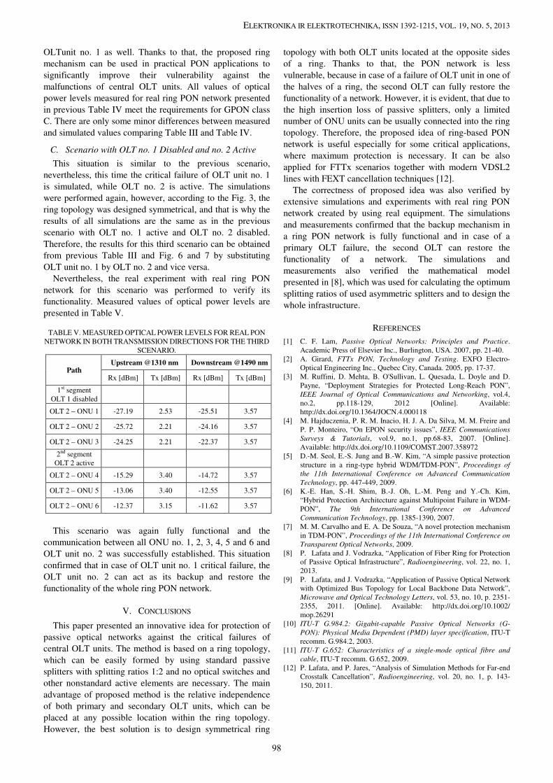
C. Scenario with OLT no. 1 Disabled and no. 2 Active
This situation is similar to the previous scenario,
nevertheless, this time the critical failure of OLT unit no. 1
is simulated, while OLT no. 2 is active. The simulations
were performed again, however, according to the Fig. 3, the
ring topology was designed symmetrical, and that is why the
results of all simulations are the same as in the previous
scenario with OLT no. 1 active and OLT no. 2 disabled.
Therefore, the results for this third scenario can be obtained
from previous Table III and Fig. 6 and 7 by substituting
OLT unit no. 1 by OLT no. 2 and vice versa.
Nevertheless, the real experiment with real ring PON
network for this scenario was performed to verify its
functionality. Measured values of optical power levels are
presented in Table V.
TABLE V. MEASURED OPTICAL POWER LEVELS FOR REAL PON
NETWORK IN BOTH TRANSMISSION DIRECTIONS FOR THE THIRD
SCENARIO.
Path Upstream @1310 nm Downstream @1490 nm
Rx [dBm] Tx [dBm] Rx [dBm] Tx [dBm]
1st segment
OLT 1 disabled
OLT 2 – ONU 1 -27.19 2.53 -25.51 3.57
OLT 2 – ONU 2 -25.72 2.21 -24.16 3.57
OLT 2 – ONU 3 -24.25 2.21 -22.37 3.57
2nd segment
OLT 2 active
OLT 2 – ONU 4 -15.29 3.40 -14.72 3.57
OLT 2 – ONU 5 -13.06 3.40 -12.55 3.57
OLT 2 – ONU 6 -12.37 3.15 -11.62 3.57
This scenario was again fully functional and the
communication between all ONU no. 1, 2, 3, 4, 5 and 6 and
OLT unit no. 2 was successfully established. This situation
confirmed that in case of OLT unit no. 1 critical failure, the
OLT unit no. 2 can act as its backup and restore the
functionality of the whole ring PON network.
V. CONCLUSIONS
This paper presented an innovative idea for protection of
passive optical networks against the critical failures of
central OLT units. The method is based on a ring topology,
which can be easily formed by using standard passive
splitters with splitting ratios 1:2 and no optical switches and
other nonstandard active elements are necessary. The main
advantage of proposed method is the relative independence
of both primary and secondary OLT units, which can be
placed at any possible location within the ring topology.
However, the best solution is to design symmetrical ring
topology with both OLT units located at the opposite sides
of a ring. Thanks to that, the PON network is less
vulnerable, because in case of a failure of OLT unit in one of
the halves of a ring, the second OLT can fully restore the
functionality of a network. However, it is evident, that due to
the high insertion loss of passive splitters, only a limited
number of ONU units can be usually connected into the ring
topology. Therefore, the proposed idea of ring-based PON
network is useful especially for some critical applications,
where maximum protection is necessary. It can be also
applied for FTTx scenarios together with modern VDSL2
lines with FEXT cancellation techniques [12].
The correctness of proposed idea was also verified by
extensive simulations and experiments with real ring PON
network created by using real equipment. The simulations
and measurements confirmed that the backup mechanism in
a ring PON network is fully functional and in case of a
primary OLT failure, the second OLT can restore the
functionality of a network. The simulations and
measurements also verified the mathematical model
presented in [8], which was used for calculating the optimum
splitting ratios of used asymmetric splitters and to design the
whole infrastructure.
REFERENCES
[1] C. F. Lam, Passive Optical Networks: Principles and Practice.
Academic Press of Elsevier Inc., Burlington, USA. 2007, pp. 21-40.
[2] A. Girard, FTTx PON, Technology and Testing. EXFO Electro-
Optical Engineering Inc., Quebec City, Canada. 2005, pp. 17-37.
[3] M. Ruffini, D. Mehta, B. O'Sullivan, L. Quesada, L. Doyle and D.
Payne, “Deployment Strategies for Protected Long-Reach PON”,
IEEE Journal of Optical Communications and Networking, vol.4,
no.2, pp.118-129, 2012 [Online]. Available:
http://dx.doi.org/10.1364/JOCN.4.000118
[4] M. Hajduczenia, P. R. M. Inacio, H. J. A. Da Silva, M. M. Freire and
P. P. Monteiro, “On EPON security issues”, IEEE Communications
Surveys & Tutorials, vol.9, no.1, pp.68-83, 2007. [Online].
Available: http://dx.doi.org/10.1109/COMST.2007.358972
[5] D.-M. Seol, E.-S. Jung and B.-W. Kim, “A simple passive protection
structure in a ring-type hybrid WDM/TDM-PON”, Proceedings of
the 11th International Conference on Advanced Communication
Technology, pp. 447-449, 2009.
[6] K.-E. Han, S.-H. Shim, B.-J. Oh, L.-M. Peng and Y.-Ch. Kim,
“Hybrid Protection Architecture against Multipoint Failure in WDM-
PON”, The 9th International Conference on Advanced
Communication Technology, pp. 1385-1390, 2007.
[7] M. M. Carvalho and E. A. De Souza, “A novel protection mechanism
in TDM-PON”, Proceedings of the 11th International Conference on
Transparent Optical Networks, 2009.
[8] P. Lafata and J. Vodrazka, “Application of Fiber Ring for Protection
of Passive Optical Infrastructure”, Radioengineering, vol. 22, no. 1,
2013.
[9] P. Lafata, and J. Vodrazka, “Application of Passive Optical Network
with Optimized Bus Topology for Local Backbone Data Network”,
Microwave and Optical Technology Letters, vol. 53, no. 10, p. 2351-
2355, 2011. [Online]. Available: http://dx.doi.org/10.1002/
mop.26291
[10] ITU-T G.984.2: Gigabit-capable Passive Optical Networks (G-
PON): Physical Media Dependent (PMD) layer specification, ITU-T
recomm. G.984.2, 2003.
[11] ITU-T G.652: Characteristics of a single-mode optical fibre and
cable, ITU-T recomm. G.652, 2009.
[12] P. Lafata, and P. Jares, “Analysis of Simulation Methods for Far-end
Crosstalk Cancellation”, Radioengineering, vol. 20, no. 1, p. 143-
150, 2011.
98