Embed Size (px)
Citation preview
Acta IV[echanica 63, 113--130 (1986) A C T A M E C H A N I C A | by Springer-Verlag 1986
Simulation of Rock Falls down a Valley Side
By
D. Bozzolo and R. Pamini, Lugano, Switzerland
With 14 Figures
(Received January 6, 1986; revised January 15, 1986)
Summary
The SASS computer model was developed to simulate the planar motion of a single rock down a mountain side. The falling rock is modelled as a rigid ellipsoidal body with axes varying between defined limits. The slope is partitioned into discrete elements, and the model accounts for sliding, rolling, impact and free flight of the individual rock. Data relating to the geology and morphology of the slope are required. With them one may calculate the distribution of linear and angular velocities of a rock along its p a t h its height of rise and its run-out distances. Varying initial and/or basal conditions permits estimation of the extent of endangered zones. Two applications illustrate the workability and usefulness of the code.
1. Introduction
The Swiss Canton 'Ticino ' lies in Alpine and Prealpine areas. Several of its
valley regions are prone to rock falls ; every year they cause ra ther severe damage
to forests, roads and buildings. For planning purposes, it is thus of u tmos t im-
por tance to be able to map out the "degrees of r isk" of the terri tory.
Motivated by Canadian researches (D. g . P i teau; [3]) we decided to develop
a model which could describe the mot ion of a single rock down ~ planar sloping
bed. The first mathemat ica l model tha t was developed defined the rock as a
simple mass point. I t s applicat ion depended on numerical values of the dynamic parameters (e.g. the coefficient of rest i tut ion and the coefficient of friction) which
were poor ly known. I n the initial stage of computa t ion these were adopted f rom the literature,
see L. Broili [1]. Later , it was decided to carry out field experiments on those
valley slopes to which our roekfall research was direct ly related and to obta in est imates for the phenomenologieal parameters f rom these observations. Scrut iny of the individual frames of the film showed tha t the ro ta t ion of the rocks could b y no means be ignored, and in order to take this into account , it was decided
to proceed to a model which t reated the rock as a rigid b o d y with ellipsoidal
shape.
8 A c t a Mech . 63./1--4
114: D. Bozzolo and 1~. Pamini:
2. Description of the Model "SASS"
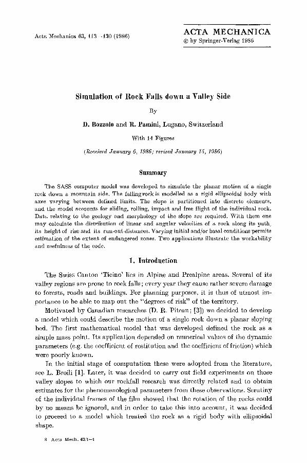
With this new model it is possible to calculate the trajectory of a rock down a sloping bed when the effects of sliding, rolling, impact and free flight are taken into account. The model is two-dimensional in that it describes the motion of the rock down a trace of successive vertical sections with the true topography. This trace is further idealized if necessary by rotating it into a common vertical plane and by approximating it by a series of straight segments. Partial allowance for the shape and the distribution of mass of the rock is made by treating it as an ellipsoid (Fig. 1). This guarantees proper dynamic modelling under free flight conditions (when aerodynamic drag can be ignored) but only part ly accounts for proper modelling under contact.
The model operates through a succession of free flights and contacts with the prescribed bed of an individual rock by integrating its equations of motion for the free flight phase and applying the principles of balance of linear and angular momentum under contact with the ground. This contact involves
~)
true ~ ~ t r a j e c t o r y ~ - ~
\ rotated ~ ~ trajectory I
STONE z b)
'y
b\
ELLIPSOID Fig. i. a Explaining how the true trajectory is mapped into a succession of straight segments within a vertical plane; b The block is replaced by an ellipsoid with three different
semi-a,xes
Simulation of Rock Falls down a Valley Side 115
impact and possibly rolling and sliding immediately afterwards. All essential quantities in the course of the motion of a rock are computed, but collisions of two flying rocks and fracturing of a rock under impact with the ground are ignored. The starting position of rocks are randomly varied within a prescribed area.
The model thus provide information regarding the dynamical properties along the trajectory, and in particular the height of flight, the linear and angular velocities of a single rock along its idealized mountain side and the run-out distances. The location where output is sought is selectable along the slope.
The test results can be presented in various ditferent ways. With random initial and/or boundary conditions distributional properties oi physical quantities can be analysed. The following selected data proved to be useful:
-- Plots of the idealized topography and the trajectories of the individual blocks (for examples see later :Figs. 13, 14), -- histograms of speeds, frequencies of rotation (angular velocities are given here as rotational frequencies), height of flight (all at a given position) and run-out distances of the blocks (for examples see later :Fig. 12), -- tables which contain the data obtained for each rock along its path in the observational plane.
Computations, of course, depend on the numerical values of several phenom- enological parameters such as a maximum value of the coefficient of restitution and minimum and maximum values of the slope angles. :For a given segment those slope angles were randomly varied between these extrema to account (i) for the difference between the true topography and the idealized trace that replaces it and (ii) the deformation of the ground due to impact. These values were however adjusted by comparison with field observations.
3. Summary of Experimental Data
In order to assign values to the phenomenological parameters of the model, three experiments were carried out oil slopes of differing morphological charac- teristics. Two aimed at an understanding of the motion of single rocks, in the third, an unstable rocky spur was blasted and resulted in the motion of an entire set of rocks of different shapes and sizes.
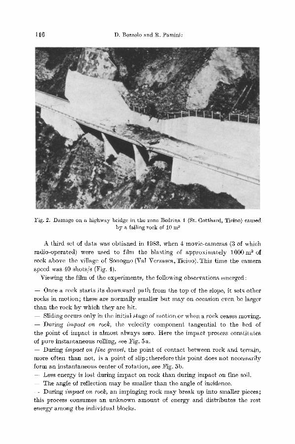
The first tests were conducted in 1981 on a slope in the Bedrina 1 area (St. Gotthard, Ticino): it was here that a falling rock had crashed through a highway bridge (Fig. 2). Three movie-cameras, placed at different positions along the test slope and operating at a speed of 24 shots/s, recorded the rocks at various stages along their trajectories, especially during the impact phase. The test slope was soft covered with a thin layer of humus.
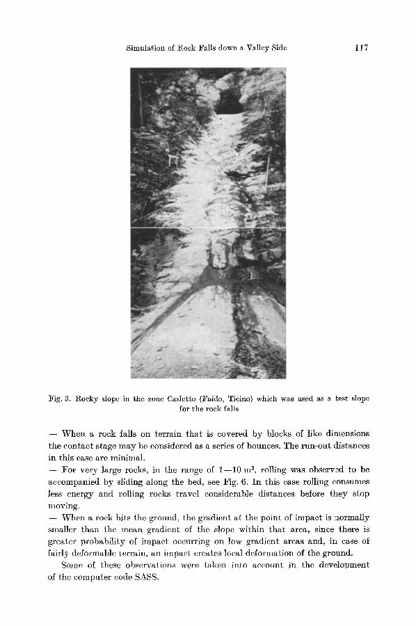
A second series of experiments was carried out in 1982 on a rocky slope in the Casletto area (Faido, Ticino [2]). On this occasion, 4 super-8 movie-cameras operating at a speed of 54 shots/s were used to record the falling rocks (Fig. 3).
8"
116 D. Bozzolo and 1%. Pamini:
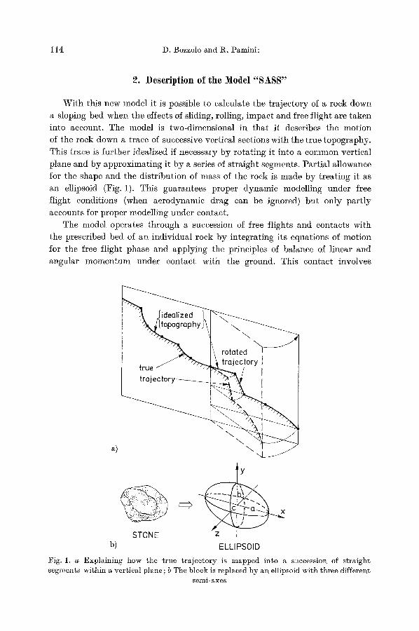
Fig. 2. Damage on a highway bridge in the zone Bedrina 1 (St. Gotthard, Ticino) caused by a falling rock of 10 m 3
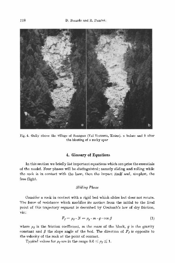
A third set of da ta was obt ianed in 1983, when 4 movie-cameras (3 of which
radio-operated) were used to film the blasting of approximate ly 1000 m a of
rock above the village of Sonogno (Val Verzasca, Ticino). This time the camera speed was 40 shots/s (Fig. 4).
Viewing the film of the experiments, the following observations emerged:
- - Once a rock starts its downward pa th f rom the top of the slope, it sets other
rocks in mot ion; these are normal ly smaller bu t m a y on occasion even be larger
than the roek b y which they are hit.
- - Sliding occurs only in the initial stage of mot ion or when a rock ceases moving.
- - During impact on rocl~, the veloci ty component tangential to the bed of
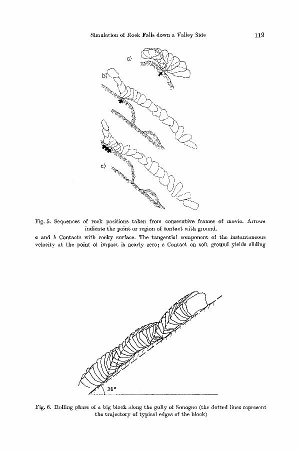
the point of impact is a lmost always zero. Here the impact process consti tutes of pure ins tantaneous rolling, see Fig. 5 a.
- - During impact on/ ine gravel, the point of contact between rock and terrain, more of ten than not, is a point of s l ip; therefore this point does no t necessarily form an ins tantaneous eenter of rotation, see Fig. 5b.
- - Less energy is lost during impact on rock than during impact on fine soil.
- - The angle of reflection m a y be smaller than the angle of incidence. - - Dur ing impact on rock, an impinging rock m a y break up into smaller pieces; this process consumes an unknown amoun t of energy and distributes the rest energy among the individual blocks.
Simulation of Rock Falls down a Valley Side 117
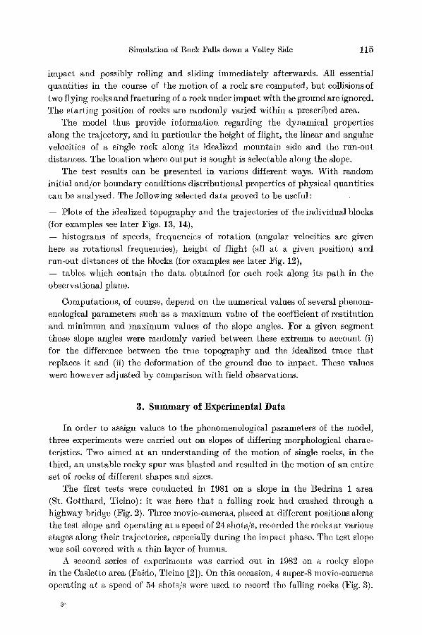
Fig. 3. Rocky slope in the zone Casletto (Faido, Ticino) which was used as a test slope for the rock falls
- - When a rock falls on terrain that is covered by blocks of like dimensions
the contact stage may be considered as a series of bounces. The run-out distances
in this ease are minimal.
- - For very large rocks, in the range of 1--10 m 3, rolling was observed to be
accompanied by sliding along the bed, see Fig. 6. In this ease rolling consumes
less energy and rolling rocks travel considerable distances before they stop
moving. - - When a rock hits the ground, the gradient at the point of impact is normally smaller than the mean gradient of the slope within that area, since there is
greater probability of impact occurring on low gradient areas and, in ease of fairly deformable terrain, an impact creates local deformation of the ground.
Some of these observations were taken into account in the development
of the computer code SASS.
t18 D. Bozzolo and I~. Pamini:
Fig. 4. Gully above the village of Sonogno (Val Verzasca, Ticino). a before and b after the blasting of a rocky spur
4. Glossary of Equations
In this section we briefly list important equations which can prise the essentials of the model. Four phases will be distinguisted; namely sliding and rolling while the rock is in contact with the base, then the impact itself and, simplest, the free flight.
Slidi~g Phase
Consider a rock in contact with a rigid bed which slides but does not rotate. The force of resistance which modifies its motion from the initial to the final point of this t rajectory segment is described by Cou]omb's law of dry friction, viz :
FI = #I" N =/~S" m . g . cos fi (1)
where #1 is the friction coefficient, m the mass of the block, g is the gravi ty constant and fi the slope angle of the bed. The direction of F I is opposite to the velocity of the rock at the point of eontaet.
Typical values for/~s are in the range 0.6 =</t! =< 1.
Simulation of Rock Falls down a Valley Side 119
Fig. 5. Sequences of rock positions taken from consecutive frames of movie. Arrows indicate the point or region o~ contact with ground.
a and b Contacts wi+,b rocky surface. The "~angential component of the instantaneous velocity at the point of impact is nearly zero; c Contact on soft ground yields sliding
/
72"
Fig. 6. Rolling phase of a big block along the gully of Sonogno (the dotted lines represent the trajectory of typical edges of the block)
120 D. Bozzolo and g. Pamini:
R o l l i n g P h a s e
Consider a rock in contact with the ground such that no sliding arises. This
phase is frequently composed of a succession of jumps in particular when the rock hits a surface with roughness scales which are comparable in dimension to those of the rock. I f the dimensions of the falling rock are much greater than those of the roughness lenghts of the base, the contact process can be defined as rolling with simultaneous slippage at the point of contact. According to
Sta tham [4], who carried out numerous laboratory and field experiments, a fairly accurate description of this complex phase can again be given by using Coulumb's law of friction with a friction coefficient that depends en the prop-
erties of the test terrain. The formula is
with
F r = ,ar " m " g " cos /~
u , = #o § k . d * / d
(2)
where/~r is a drag coefficient typical of rolling, and #0, k are constants (0.37 =< r =< 0.67, 0.17 _< k _<_ 0.26, see [4]) while d* and d are characteristic diam- eters of the rocks of the bed and the rolling block, respectively. The direction
of F ! is again tangential to the base. Numerical values for #r tend to be smaller
than those for/~s"
I m p a c t P h a s e
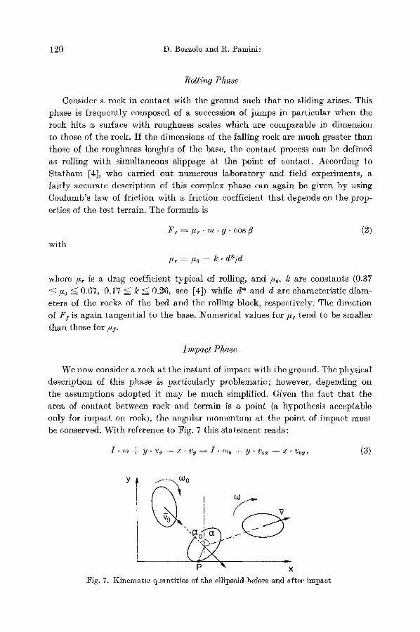
We now consider a rock at the instant of impact with the ground. The physical description of this phase is particularly problematic; however, depending on the assumptions adopted it may be much simplified. Given the fact that the area of contact between rock and terrain is a point (a hypothesis acceptable only for impact on rock), the angular momentum at the point of impact must be conserved. With reference to Fig. 7 this s ta tement reads:
I - co ~- y . vx - - x . v~ = I - coo § y" vo~ - - x- Vow, (3)
y t
p X ~x Fig. 7. Kinematic qaanti~ies of the ellipsoid before and after impact
Simulation of Rock Falls down a Valley Side 121
where I is the moment of inertia per unit mass and with respect to the centre of mass; co0, ~o are the angular velocities before and after th 9 impact (clockwise rotations considered positiv), x, y are the coordinates of the centre of mass in a Cartesian frame and v0x, vx and Vov, vv are the velocity components of the centre of mass before and after impact, respectively, compare Fig. 7.
Scrutiny of the individual photographs of the films shows that the friction between impinging rock and rocky surface is normally sufficiently high to prevent any horizontal displacement of the point of impact P. This is demonstrated in Fig. 5a, b. Thus the point of contact becomes an instantaneous center of rotation, and the relationships for the tangential and normal components of
the velocity of the centre of mass are
v~ = y . ~ , v v = - - x . ~ . (4)
Combining (3) and (4) ~elds
( I . ~ % + y . v o , - - x . Voy)
( I + x 2 + y 2) (5)
one obtains
1 K ---- ~ - ( I - ~o 2 + v~ ~ § v~ ~)
( I . ~o0 § y" v0. - - x - v0,) 2 (6)
~mln= ( I .o)o 2 § v~x § v~x ) " (I § x ~ § y~)
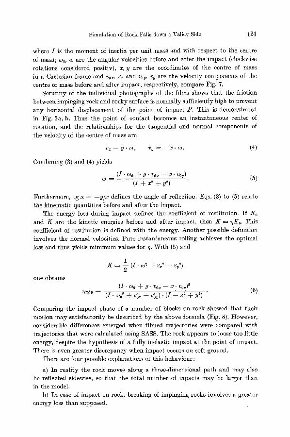
Comparing the impact phase of a number of blocks on rock showed that their motion may satisfactorily be described by the above formula (Fig. 8). However, considerable differences emerge d when filmed trajectories were compared with trajectories that were calculated using SASS. The rock appears to loose too little energy, despite the hypothesis of a fully inelastic impact at the point of impact. There is even greater discrepancy when impact occurs on soft ground.
There are four possible explanations of this behaviour :
a) In reality the rock moves along a three-dimensional path and may also be reflected sidewise, so that the total number of inpacts may be larger than in the model.
b) In case of impact on rock, breaking of impinging rocks involves a greater energy loss than supposed.
Furthermore, tg o~ = - - y / x defines the angle of reflection. Eqs. (3) to (5) relate the kinematic quantities before and after the impact.
The energy loss during impact defines the coefficient of restitution. If Ko and K are the kinetic energies before and after impact, then K----uK0. This coefficient of restitution is defined with the energy. Another possible ,definition involves the normal velocities. Pure instantaneous rolling achieves the optimal loss and thus yields minimum values for ~]. With (5) and
122 D. Bozzolo and R. P~mini:
al vc (m/s)
/ o
1 ~ "~
0
V m (m/s) % (Hz)
b) 4.0
3.0 ~ o
2.0
0
1.0 . . . . . . . . . 2'.0 3.0 f~ (Hz)
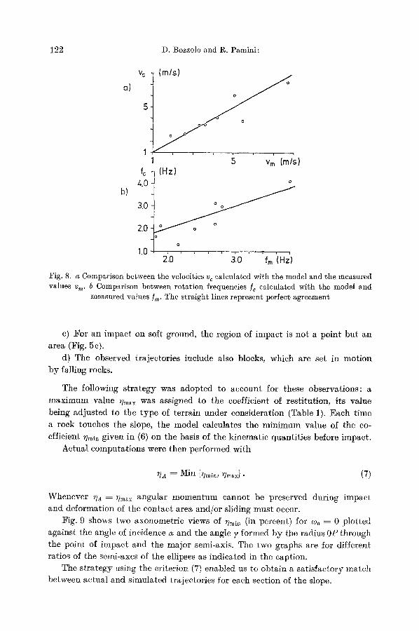
Fig. 8, a Comparison between the velocities v c calculated with the model and the measured values v m. b Comparison between rotation frequencies fc calculated with the model and
measured values/m" The straight lines represent perfect agreement
c) For an impact on soft ground, the region of impact is not a point but an area (Fig. 5c).
d) The observed trajectories include also blocks, which are set in motion by falling rocks.
The following strategy was adopted to account for these observations: a
maximum value ~Tm~x was assigned to the coefficient of restitution, its value
being adjusted to the type of terrain under consideration (Table 1). Each time
a rock touches the slope, the model calculates the minimum value of the co-
efficient ~min given in (6) on the basis of the kinematic quantities before impact. Actual computations were then performed with
UA : Min {~]min, Umax}. (7)
Whenever U• = )~max angular momentum cannot be preserved during impact and deformation of the contact area and/or sliding must occur.
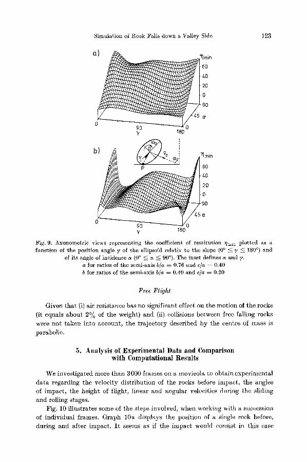
Fig. 9 shows two axonometric views of Vmi~ (in percent) for ~o0 = 0 plotted against the angle of incidence r and the angle y formed by the radius 0P through the point of impact and the major semi-axis. The two graphs are for different ratios of the semi-axes of the ellipses as indicated in the caption.
The strategy using the criterion (7) enabled us to obtain a satisfactory match between actual and simulated trajectories for each section of the slope.
Simulation of l~ock Falls down a Valley Side 123
a)
0 90 y 180
b) ~ % i
0 90 y 180
~ rain +; 4O
0
ff
0
3]min
4O
0
Fig. 9. Axonometric views representing the coefficient of restitution ~n,ln plotted as a function of the position angle ? of the ellipsoid relativ to the slope (0 ~ ~ ? ~ 180 ~ and
of its angle of incidence a (0 ~ --~ a --~ 90~ The inset defines ~ and y. a for ratios of the semi-axis b/a ~ 0.76 and c/a ~ 0.40
b for ratios of the semi-axis b/a ~ 0.40 and c/a ~ 0.20
F r e e F l i g h t
Given tha t (i) air resistance has no significant effect on the mot ion of the rocks
(it equals about 2% of the weight) and (ii) collisions between free falling rocks
were no t taken into account , the t r a jec to ry described b y the centre of mass is
parabolic.
5. Ana lys i s of E x p e r i m e n t a l D a t a and Compar i son wi th C o m p u t a t i o n a l Resu l t s
We investigated more than 3000 frames on a movieola to obtain experimental
da ta regarding the veloci ty distr ibution of the rocks before impact, the angles of impact , the height of flight, linear and angular velocities during the sliding
and rolling stages. Fig. 10 illustrates some of the steps involved, when working with a succession
of individual frames. Graph 10a displays the posit ion of a single rock before,
dur ing and after impact . I t seems as if the impact would consist in this case
124 D. Bozzolo and R. Pamini:
/ -/~/~p
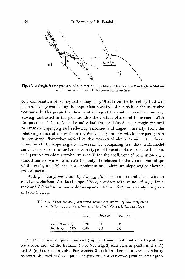
Fig. 10. a Single frame pictures of the motion of a block. The stake is 2 m high. b Motion of the centre of mass of the same block as in a
of a combinat ion of rolling and sliding. Fig. 10b shows the t ra jec tory tha t was
constructed by connecting the approximate eentres of the rock at the successive
positions. I n this graph the absence of sliding at the contact point is more con-
vincing. Indica ted in the plot are also the contact plane and its normal. Wi th
the posit ion of the rock in the individual frames defined it is s t raight forward
to est imate impinging and reflecting velocities and angles. Similarly, f rom the
relative position of the rock its angular velocity, or the ro ta t ion f requency can
be estimated. Somewhat critical in this process of identification is the deter-
minat ion of the slope angle ft. However, b y comparing test da ta with model simulations performed for two extreme types of impact surfaces, rock and debris,
it is possible to obta in typical values: (i) for the coefficient of rest i tut ion Vm~x,
(unfor tunate ly we were unable to s tudy its relation to the volume and shape
of the rock), and (ii) the local m a x i m um and min imum slope angles about a typical mean.
Wi th p = tan fl, we define b y Apmln,max/p the min imum and the m a x i m u m relative variat ions of a local slope. These, together with values of ~?max, for a rock and debris bed on mean slope angles of 44 ~ and 57 ~ respectively are giver~ in table 1 below.
Table 1. Experimentally estimated maximum values o/ the coe/]icient o] restitution r]n~ax, and extremas o/local relative variations in slope
~lmax Apmin/P dpm~x/P
rock (fl ~ ~:4 ~ 0.70 0.0 0.3 debris (fl = 57 ~ 0.55 0.2 0.6
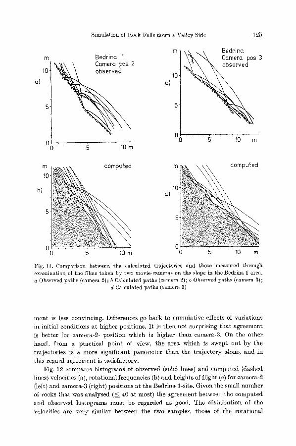
I n Fig. 11 we compare observed (top) and computed (bottom) trajectories for a local area of the Bedrina l-site (see Fig. 2) and camera positions 2 (left) and 3 (right), respectively. :For camera-2 position there is a great similarity between observed and computed trajectories, for camera-3 position this agree-
Simulation of Rock Falls down a Valley Side 125
ct
m
10"
5
0
Bedrino 1
observed
0 I'O m
m Beeino Camera pos 3
10.
.
~ 6
m
10
b)
I~" t~ ~ ~ I I ~" ~ / ' I ~ m
d) 10.
al
0 0 0 5 10 m 0 5 10 m
Fig. 11. Comparison between the calculated trajectories and those nmasured through examination of the films taken by two movie-cameras on the slope in the Bedrina 1 area. a Observed paths (camera 2) ; b Calculated paths (camera 2) ; c Observed paths (camera 3) ;
d Calculated paths (camera 3)
ment is less convincing. Differences go back to cumulative effects of variations in initial conditions at higher positions. I t is then not surprising that agreement is better for camera-2- position which is higher than camera-3. On the other hand, from a practical point of view, the area which is swept out by the trajectories is a more significant parameter than the trajectory alone, and in
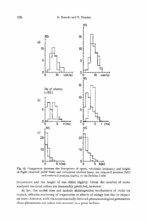
this regard agreement is satisfactory. Fig. 12 compares histograms of observed (solid lines) and computed (dashed
lines) velocities (a), rotational frequencies (b) and heights of flight (e) for camera-2 (left) and camera-3 (right) positions at the Bedrina 1-site. Given the small number of rocks that was analysed ( ~ 40 at most) the agreement between the computed and observed histograms must be regarded as good. The distribution of the velocities are very similar between the two samples, those of the rotational
126 D. Bozzolo and R. :Pamini:
NS
a) NS
10 r'l I i ! i
O0 10 v{m/s)
15
10
"1
; t 5 :
0 0 10 v(m/s) NS
b)
c) 20
10
No. of stones (=NS)
L!,,,, ,',' L - 7
06:' " g " i(Hzi ,NS
i
1
I
o
i
O0 g h(m)
15 r - 1
- I
r - 4 . . . , . . �9
~ 5 f (H=z) NS
20: -i,, i
t | i
t
10 '
i i
0 0 5 h(rn}
Fig. 12. Comparison between the histograms of speed, rotational frequency and height of flight observed (solid lines) and calculated (dashed lines), for camera-2 position (left.)
and camera-3 position (right), at the Bedrina l-site
frequencies and the height of rise differ slightly. Given the number of rocks
analysed maximal values are reasonably predicted, however. So far, the model does no t include disintegration mechanisms of rocks on
impact, sidewise scattering of trajectories or effects of energy ]oss due to impact on trees; however, with the experimental ly deduced phenomenological parameters these phenomena are taken into account in a gross fashion.
Simulation of Rock Falls down a Valley Side 127
6. Applications
Even though the individual t rajectory of a rock may not be adequately predicted by SASS, it definitely permits deductions of reliable results when random conditions (the usual situation) prevail. In this sense our model is very
useful as a tool of design. In particular the model enable us
- - to determine the probabil i ty of impact on existing or projected structures
by rocks which have been set in motion,
- - to determine the optimal site for safety structures and to obtain data for
their design,
- - to determine the areas where rocks will cease to move (zoning),
- - to evaluate the feasibility of measures to prevent or limit rocks from falling
off a mountain,
- - to obtain necessary data for the design of save-guard tunnels against falling
stones.
To make adequate use of the model a geological survey of the area concerned must be carried out: it should provide the information essential to the simulation,
i.e. the dimensions of the rocks existing on the slope and of those likely to break off the rock face, the topology and morphology of the section, estimates for
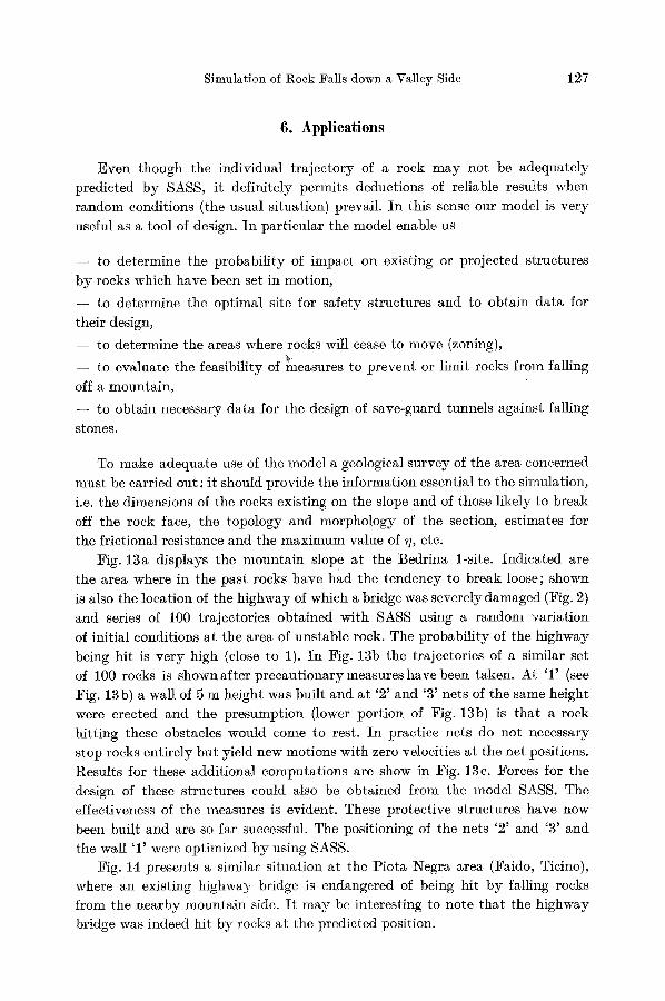
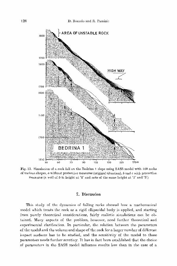
the frictional resistance and the maximum value of ,], etc. Fig. 13a displays the mountain slope at the Bedrina 1-site. Indicated are
the area where in the past rocks have had the tendency to break loose; shown is also the location of the highway of which a bridge was severely damaged (Fig. 2)
and series of 100 trajectories obtained with SASS using a random variation of initial conditions at the area of unstable rock. The probabil i ty of the highway being hit is very high (close to 1). In Fig. 13b the trajectories of a similar set of 100 rocks is shown after precautionary measures have been taken. At '1' (see
Fig. 13b) a wall of 5 m height was built and at '2 ' and '3' nets of the same height were erected and the presumption (lower portion of Fig. 13b) is that a rock hitting these obstacles would come to rest. In practice nets do not necessary stop rocks entirely but yield new motions with zero velocities a t the net positions.
Results for these additional computations are show in Fig. 13e. Forces for the design of these structures could also be obtained from the model SASS. The effectiveness of the measures is evident. These protective structures have now
been built and are so far successful. The positioning of the nets '2' and '3' and the wall T were optimized by using SASS.
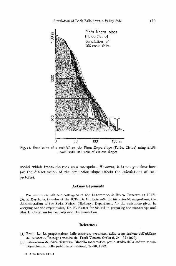
Fig. 14 presents a similar situation at the Piota Negra area (Faido, Tieino), where an existing highway bridge is endangered of being hit by falling rocks from the nearby mountain side. I t may be interesting to note that the highway bridge was indeed hit by rocks a t the predicted position.
128 D. Bozzolo and g . Pamini:
1800
1750
1800
1750
1800
1750
I700
1650 30 50 70 90 110 130 150 170m
Fig. 13. Simulation of a rock fall on the Bedrina 1 slope using SASS model with 100 rocks of various shapes, a without protective measures (original situation), b and c with protective
measures (a well of 5 m height at '1' and nets of the same height at '2' and '3')
7. Discussion
This s t u d y of the dynamics of fal l ing rocks showed how a m a t h e m a t i c a l
model which t r ea t s the rock as a r igid e l l ipsoidal b o d y is appl ied , and s t a r t ing
f rom p u r e l y theore t ica l considerat ions , f a i r ly real is t ic s imula t ions can be ob-
ta ined. M a n y aspec ts of the problem, however , need fur ther theore t ica l and
expe r imen t a l clar if icat ion. I n pa r t i cu la r , the re la t ion be tween the p a r a m e t e r s
of the model and the vo lume and shape of the rock for a la rger n u m b e r of d i f ferent
i m p a c t surfaces has to be s tudied, and the sens i t iv i ty of the model to these
p a r a m e t e r s needs fu r the r sc ru t iny . I t has in fac t been es tab l i shed t h a t the choice
of p a r a m e t e r s in the SASS model inf luence resul ts less t han in the ease of a
Simulation of Rock Falls down a Valley Side 129
E 0 0
0 0 0
0 0
0 50 100 150 m
:Fig. 14. Simulation of ~ rockfall on the Piota Negra slope (Faido, Ticino) using SASS model with 100 rocks of various shapes
model which t r ea t s the rock as a masspoin t . However , i t is no t y e t clear how
fa r the d iscre t iza t ion of the s imula t ion s lope affects the calcula t ions of t ra -
jectories .
Acknowledgements
We wish to thank our colleagues of the Laboratorio di Fisica Terrestre at ICTS, Dr. M. Martinola, Director of the ICTS, Dr. G. Beatrizotti for his valuable suggestions, the Administration of the Swiss Federal Highways Department for the assistance given in carrying out the experiments, Dr. K. Huttcr for his aid in preparing the manuscript and Mrs. E. Castellani for her help with the translation.
References
[1] Broili, L.: La progettazione delle strutture paramassi nella progettazione dell'utilizzo del territorio. Rassegna tecnica del Friuli Venezia Giulia 2, 25--31 (1979).
[2] Laboratorio di Fisica Terrestre: Modello matematico per lo studio della caduta massi. Dipartimento della pubblica educazione, 1--80, 1982.
9 Acta Mech , 63/I--4

130 D. Bozzolo and g. Pamini: Simulation of Rock Falls down a Valley Side
[3] Piteau, D. 1%.: Computer rockfall model. Pubblicazione ISMES (Bergamo, Italy) 90, 1976.
[4] Statham, I. : A simple dynamic model of rockfalh some theoretical principles and model and field experiments. Iaternational Colloquium on physical and geomechanical 5Iodels, ISMES (Bergamo, Italy), 1979.
D. Bozzolo and R. Pamini Istituto Cantonale Tecnico Sperimentale (ICTS)
Laboratorio cli Fisica Terrestre CH- 6952 Canobbio
Switzerland