Embed Size (px)
Citation preview
.-J
AD 4
S/LI IJIIII/i3Y JIII Y IZIZ
SIMULATION OF THE STATE OF THEM42/M46 GRENADE DURING PRESS LOADING
GEORGE J. SCHLENKER
g ,l
DECEMBER 1985
Cn
Distribution .Statement
I Approved for public-release; distribution unlimited.
0N
1ýLEGTE
U.S. ARMY ARMAMENT, MUNITIONS AND CHEMICAL COMMANDREADINESS DIRECTORATE
"ROCK ISLAND, ILUNOIS 61299-6000 01 "
* .~ ** * *~1*4,
* * *'~~/,- I. NW~ _%1
DIS2OSITION
Destroy this repo-t when no longer needed. Do notreturn it to the originator.
DISCLAIMER
The findings in this report are not to bi construed asan official position of either the Department of the ArmySor of the US Army Armament, Munitions and Chemical Command.r..f - C C ' Vo '¶ C t
-- -
, 2: 9 -.. {
AMSMC/RD/MR-7
SIMULATION OF THE STATE OF THE
M42/M46 GRENADE DURING PRESS LOADING
George J. Schlenker
December 1985
"UNCLASSIFIED-)SECURITY CLASSIFICATION OF 7-HI, PAGE (When Doet Entered)
REPORT DO)CUMENrATION PAGE READ INSTRUCTIONSBEFORE COMPLETING FORM
[-I. REPORT NUMOER 2. GVT ACCESSION NO 3.RE IPIENT'S CATALOG NUMBER
AMSMC/RD/MR-74. TITLE (and Subtitle) 3. TYPE OF REPORT & PERIOD COVERED
Simulation of the State of the M42/M46 Grenade Report - FinalDuring Press Loading
6. PERFORMING ORG. REPORT NUMBER
7. AUTHOR(&) 8. CONTRACT OR GRANT NUMBER(a)'
George J. Schlenker
9. PERFORMING ORGANIZAT!ON N.AME AND ADDRESS 10. PROGRAM ELEMENT, PROJECT. TASK
US Army Armament, Munitions and Chemical Command AREA & WORK UNIT NUMBERSReadiness DirectorateRock Island, IL 61299-6000
I1. CONTROLLING OFFICE NAME AND ADDRESS 12. REPORT DATEDecember 1985
13. NUMBER OF PAGES
_ __-_ _ _6414. MONITORING AGENCY NAME & ADDRESS('l different from Controlling Office) 15. SECURITY CLASS. (of this report)
UNCLAS
15s. DECLASSI FICATION/DOWNGRADINGSCHEDULE
16. DISTRIBUTION STATEMENT (of thie Report)
"Approved for public release; distribution unlimited.
17. DISTRIBU'TION STATEMEN r (of the abstract entered in Block 20, if different from Report)
Additions to/from the DISTRIBUTION LIST are invited and should be forwarded tothe following address: Commander, US Army Armament, Munitions and ChemicalCommaod, ATTN: AMSMC-RDA-S, Rock Island, IL 61299-6000 AUTOVON 793-5041/6370
18. SUPPLEMENTARY NOTES
IS. KEY WORDS (Continue or, reverse side It necessary and Idewiftly by block number)
Operations Research, Explosive ,IncidentsContinuous Simulationc Energetic MaterialsIndustrial Operations. Pressed Composition A-5SPress Loading Numerical Methods,
"... 20. ABSTRACT (Continue on reverse stae if necessary and ldenitfr by block number)
This report is a contribution to an ongoing study of explosive incidents (blows)which occur during press loading of the M42/M46 grenade. One of the causalmechanisms posited for the blows is brittle fracture of the grenade body. Thephysical state of the grenade during final consolidation is of critical impor-tance for this mechanism. A detailed simulation of the compression phase offinal loading helps to verify the feasibility of this causal mechanism and tosuggest means of minimizing a part of the rate of incidents. This report
FOA
SD AN3 473 LDITION OF I NOV S5 IS OBSOLETEDD 1473 E UNCLASSIFIED
SECURITY CLASSIFICATION OF T',IS PAGE (Plien Dat. Enterd)
----... ,
•-w• ,•;•. • •;,• .w -• • •`•-•'•%-• •'•`'•'d• 'iL•;•=`•`-•`•l•J•<• `• ;•T1• •1• i•i•i•-;¸•¸. .•.• • .• •,•-•.• •.-.• W• •. "..,• ",, " , •," .•
•,i UNCLASS I F i ED
•-;•,; Block 20 (Continued)
•'i•'•." • describes a continuous simulation of several related phenomena wnich occur
S/ during final consolidation. These phenomena include: (a) compaction uf the• bulk HE, (b) production of elastic strain in the grenade body, (c) elastic
•'. compression of RDX particles in the HE, (d) kinematics of the punch, (e) heat-•i'- ing of the HE, and (f) diffusion of heat within the grenade. A s•mple of.'." simul•tion results is given in graphical form with key variables displayed as,- functions of punch displacement and of time. Sensitivity o$ results to certain
_ parameters is shown. Comparisons are made between some experimental measure-m
,• ments and results of the simulation. These comparisons demonstrate the validity• of the simulation within the limits imposed by its scope. For the interested
•i•\.... analyst, the implementing computer program is listed and explained. I¢ ,,.,•, ,,/•
.@° -
UNCLASSIFIED
•-" . . . . . . .... • - - "- - - "- " - " - "• "" • - " - • - " °" - " • ' -" - "-" - " -" •" • •, "•.r-" -'" -'- -'" -" "" •' •'•" •"W°•'W •"- "'• •'.•k• --''•-''-'\'-. "'-'" •
EXECUTIVE SUMvMARY
This report is a contribution to an ongoing study of explosiveincidents (blows) which occur during press loading of the M42/M46grenade. High explosive (HE) Composition A-5 is pressed into asteel Lody (either M42 or M46) of the grenade in two operations:pre- and final -consolidation. The latter is nearly always whereblows occur. Several causal physical mechanisms for blows have beenhypotnesized. One of these mechanisms involves brittle fracture ofthe grenade body. If a crack opens and propagates, the rapid releaseof elastic strain energy at the interface of the body wall and HE fillappears to be capable of igniting the HE. The physical states of thegrenade body and of the HE during the compaction phase of final con-solioation are critical to this mecnanism. Quantification of thesestates helps to verify the feasibility of the brittle-fracture mech-
anism and to suggest means of minimizing the portion of tne blow ratecontributed by this mechanism. This report describes a continuoussimulation of several, related physical processes which occur duringthe final consolidation of the HE in the M42/M46 grenade. Typicalsimulation results are presented in graphical form, with pertinentvariables displayed as functions of both punch displacement and time.The sensitivity of these results to certain parameters is shown. Forexample, punch travel and work done by the punch are shown to be
% sensitive to the initial, preconsolidated system state. Also the maxnoop stress and noop strain energy a,'e sensitive to peak punch pres-sure. Where possible, comparisons are made between experimental dataand results of the simulation. These comparisons demonstrate thevalidity of tne simulation within tne limits imposed :y its scope.For the interested analyst, the implementing computer program islisted and explained.
Accession For
NTIS GRA&IDTIC TABUnannounced .
•--.-.- ~Just if icat ionL____
By-Distribution/
Availability Codes-Avail and/or
4 Dist Special
. -- -
....- .....v ... ..-.- ., ....... ... ..... -..... ,, ..... .... ............-..-.. -..-. ... .... . . . . . . .-. ........ :... ..... . . . . . . . . . . . . . . . . . . . . ... :.: ..:.
•.-
CONTENTS
Page
List of Tables ....................................... ii
List of Figures ....................................... iii
Forewora .................. . e .......... .. ........ 1
References .......................................... 1
Background ............................ ................ 2
Goals of the Simulation ............................... 3
Scope and Assumptions ................................. 3
Results of the Simulation ............................. 4
Parametric Analyses .................................... 4
Discussion of Results ................................ 17
Validation of the Model ............................... 18
Methodology ........................................... 19
Model Equations ...................................... 21
Temperature in an RDX Particle ........................ 26
Distribution .......................................... 28
Annex A... Computer Source Program: COMPACT .......... A-1
Annex B. Predicted Bulk Densities of Composition A-5and Composition A-4 as Functions of Peak
Consolidption Pressure ....................... B-I
t•V.
--- - - .
LIST OF TABLES
Table Page
1. Sample Output from the Computer Program: COMPACT 5
2. Sensitivity of Simulation Output to Body Wall
Thickness 6
3. Sensitivity of Simulation Output to EffectiveBody Length 6
4. Sensitivity of Simulation Output to Initial SystemState 6
5. Sensitivity of Simulation Output to Peak PunchPressure 6
ii
4-LK" Wý ,rtI V7,"r~ý(
"LIST OF FIGURES
Figure Page
1. Avg Density of HE as a Function of Punch Displacement 7
2. Max Pressure on the HE Versus Punch Displacement 7
3. -`corp L.rain Energy and Max Hoop Stress in the Grenade7>-cIy Versus Punch Displacement 8
4. Avg Density of the HE Versus Max HE Pressure 8
5. Max Hoop S+-ress in Grenade Body Versus Max HE Pressure 9
6. Hoop Strain Pnergy in the Grenade Body Versus Max HEPressure 9
7. Comparison (r Several Variables as Functions ofPunch Displacement 10
Comparison c- Several Varj.ables Versus Avg HE Density 10
- .'-. '. Work Done by the Punch as a Function of PunchDisplacement 11
10. Comparison of Energy Components as Functions of_ Punch Displacement 11
11. Punch Displacement Versus Cycle Time 12
12. Avg Density of the HE Versus Cycle Time 12'-A
13. Max HE Pressure Versus Cycle Time 13
14. Max Hoop Stress Versus Cycle Time 13
15. Punch Work Versus Cycle Time 14
16. Comparison of Energy Components as Functions ofCycle Time 14
17. Avg HE Temperature Rise as a Function of PunchJ, Displacement 15
18. Avg HE Temperature Rise as a Function of Cycle Time 15
19. Radial Profile of Temperature in an RDX Particle 16
20. Experimental Consolidation Load Versus Cycle Time 16
.. . .,,. ,. il
AMSMC-RDA-S December 1985
MEMORANDUM REPORT
SUBJECT: Siuulation of the State of the M42/M46 Grenade During':•['['[Press Loading
1. Foreword
Order of topics in this report represents increasing detail. Back-
ground information is presented first to set a context and to motivatethe work presented here. The goals of the subject simulation aregiven next, followed by the scope of- and assumptions for -the sim-ulation. Simulation results are given in tables and graphs, followedby comments about these results. Sections on validation and method-ology complete the body of the report. A source program listing ofthe simulation is given in Annex A. Annex B contains a memorandum
-:. concerning a model of the bulk density of Comp A-5. The followingreferences are cited thruout the report.
2. References
a. MFR, AMSMC-RDA-S, 22 Oct 85, subject: Evidence for a Steel-Supplier Effect on the Rate of Press Blows in M42 and XM77Grenades.
b. Technical Report ARLCD-TR-79002, Collett, R.W'. and England J.T.,ARRADCOM, LCWSL, Dover, NJ, Jun 79, title: Press LoadingTncident Investigation of M42/M46 Grenade Bodies.
c. MFR, AMSMC-RDA-S, 9 Aug 85, subject: Some Observations Aboutthe Explosive Sensitivity of Comp A-5.
d. MFR, AMSMC-RDA-S, 28 Aug 85 (Revised 24 Sep 85), subject:Predicted Bulk Densities of Comp A-5 and Comp A-4 as Functionsof Peak Consolidation Pressure. (Given in Annex B.)
e. Technical Report #371, 23 Aug 85, Day & Zimmerman Kansas Div.,subject: Investigation of Effects of Charge Density on Penetra-tion in M42/M46 Grenades.
f. MFR, DRSMC-SAS (R), 4 Nov 83, subject: Particle-Size Distribu-tion of Nominal Class 1 RDX Before Incorporation and After Ex-traction From Extrusions of Comp C-4.
g. Reference Book, Kaye, S.M., US ARDC, Dover, NJ, c. 1980,title- Encyclopedia of Explosives and Related Items, Vol 9.
"h. Text Book, Timoihenko and Goodier, McGraw-Hill, NY, c. 1951,
title: Theory of Elasticity.
i. MFR, AMSMC-RDA-S, 23 Aug 85, subject: Time Series Analysis ofthe Peak Consolidation Load for Pressing of HE into M42/M46Grenades.
3. Background
Previous studies of explosive incidents during press loading ofM42/M46 grenades posited various physical mechanisms for initiatingan explosion. Ref 2a presents arguments supporting the mechanism
Sof brittle fracture of the grenade body. The scenario for an ex-
Splosion with this mechanism is as follows: During final consolida-tion of the HE (Comp A-5), a latent crack sudden3y opens and propaga-tes. A rapid release of elastic strain energy in tne grenade body
-. is deposited at the surface of the HE in proximity to the cracK. Thisenergy release over a small area is rega.7ded as sufficient to initiatean explosion of the HE *. if this mechanism is responsible for some ofthe incidents, one would expect to see the observed variation in blowrate between bodies by different body producers, since variation inmetal parts quality oetween producers is quite evident. Ref 2b alsopresents evidence for a steel-supplier effect, which, again, is germaneto tne mecnanism of brittle fracture. A similar phenomenon, occurringin the powder nest, is one of the mechanisms hypothesized in Ref 2b.The very limited set of experiments reported in Ref 2b failed todemonstrate a blow with either a cracked oody or a cracked nest. How-ever, these negative results are not persuasive, because only rareand special conditions--very rapid energy deposit in a small area--must exist in order to provoke a blow. Based on simulated results,
brittle fracture must still be considered a credible mechanism.
-4. Considering tnis mechanism, several actions to reduce the frequencyof press blows are appropriate: (a) Improve the specified quality,including fracture toughness, of steel used in making grenade bodies.This action is suggested in Ref 2a. (b) Improve quality of grenadebodies from the "marginal" body producers. Actions started by AMCCOMQuality Assurance in 1985 address tnis issue. (c) Use a less sensitiveHE fill, such as Comp A-4. This idea is still on the back burner.(d) Load at a lower peaK consolidation pressure. This suggestion ismade in Ref 2c, and justified by data which snow reduced explosivesensitivity when grain breakage is minimized. Altho easy to imple-ment, the last suggestion has met resistance on the grounds thateffectiveness (penetration & letnal area) would suffer. Nevertheless,
4.1! some tradeoff here seems possible to reduce olow rates.
5. Because of the importance of the state of stress of the grenadebody to the brittle fracture mechanism, some effort was made totake experimental measurements (for example, Ref 2b). And, becauseof the importance of HE density to grenade performance, various data
nave oeen gathered relating HE density to peak consolidation load(or pressure), under botn quasi-static (very slow rate of loauing) andtransient conditions (wnich occur in load plants). Some of these
experimental results are comparea witn simple mathematical models inRef 2d. Ref 2e presents additional results for the transient loading
condition, in a study designed to relate avarage HE density to grenade
penetration performance. Notwithstanding tnese experiments to under-stand the processes occurring during press loading, to my knowledge no
unified mathematical model nas been developed to simulate the physicalprocesses which interact during final consolidation. This memorandumpresents such a model. Tno the simulation is not very sophisticated,model output is in good agreement with pertinent experimental data.
* Ref 2g indicates that the thre3hold value of energy per unit area
for shock ignition of RDX is about 10 cal/sq cm, a value whichmay be achieved by release of elastic strain energy in the body.
2
. L--

6. Goals of the Simulation
The primary goal of the simulation is to achieve better understanding"of the relationship of several physical parameters pertinent to load-ing of the M42/M46 grenade. Understandings of this sort ultimatelyguide design of experiments and help to quantify improvement in rateof press blows, expected to accompany loading at lower peak pressure.A partial list of questions addressed by the simulation may clarifymy intentions:
(a) How does the HE respond to punch displacement during consolid-ation? For example, how does punch load vary with punchdisplacement and with time? (In this case, time is simplya convenient variable for use in comparison with experimentalresults. Since punch acceleration is quite low, inertial forcesare not important. The phenomena are mostly kinematic ratherthan dynamic.)
(b) How does the work done by the punch vary as a function of punchdisplacement and as a function of time?
(c) What portion of the punch work is invested in elastic, i.e.,recoverable, energy components? This question has a bearing onvolume change in the HE following punch withdrawl. Also, theseelastic strain-energy components would become sources of energy
for initiating an explosion of the HE, if a metal failureoccurred during compression.
(d) Are physically significant temperature gradients developedwithin the RDX particles during consolidation?
(e) Do any of the variables of interest display a large sensitivityto the initial conditions for final consolidation, i.e., doesvariation in preconsolidation affect final results?
(f) How well does the model match the experimental load-versu.-time data?
"It is beyond the scope of this model to address issues such as:pm C(a) Specifically, what happens if a brittle fracture of a grenade
t.'".' -body occurs during consolidation?
(b) What stress concentrations occur in various regions of the body?
(c) Where does RDX grain fracture occur during loading, and what isits extent?
(d) What is the nature of the flow in the HE during consolidation?
7. Scope and Assumptions
In terms of fidelity to geometric details of the grenade body, ',hemodel is quite crude. For the purpose of calculating hoop stre.ss andhoop strain in the body, the grenade is modeled as a regular cylin-drical sleeve, supported on one end by a smooth, unyielding surface.The HE configuration is assumed to have cylindrical symmetry
_z V
within the cavity. The simulation model is descriptive; it usessemiempirical results whee'e appropriate, and does not insist onstarting from first principles. In spite of evidence of RDX grain"fracture, cited in Refs 2c and 2f, the model ignores this phenomenon."Further, because of its simple geometry, no attempt is made todescribe the actual flow of the HE with respect to the punch andbody cavity in an actual M42/M46 grenade. However, the effects ofa pressure gradient within the HE are considered. Most of themechanical and thermal material characteristics were obtained from"standard references such as Ref 2g. The compaction model (avg HE
'~ density versus peak pressure) uses the functional form described inAnnex B. This model assumes a constant pressure gradient within theHE. The pressure decreases linearly from a maximum value of pmax,at the punch face, to a minimum value of a constant, g, times pmax.The value of g used here (0.6) is obtained from data in Ref 2e. Theassumed constant pressure gradient within the HE is also used inderiving an expression for the RDX elastic strain energy. Hoop stressin the simulated grenade body is calculated using the Lame equation forthick-walled cylinders (Ref 2h). A formula for body strain energyis derived from the last equation, which assumes elastic behavior.
8. Results of the Simulation
The loading simulation is implemented by a computer program COMPACT.A source listing of this program, in Simscript 2.5, is located in"Annex A. The logic of this program is sketched below (p. 19, Method-ology). A portion of the output from COMPACT is shown in Table 1.After echoing the input parameters, the state variables, whichcharacterize the hE and the grenade body, are printed as functionsof the displacement of the punch. The initial, average density ofthe HE is chosen by the program user. This value suffices to init-ialize the simulation for tae final consolidation cycle. Punch dis-placement and cycle time are taken as zero at this point. Time iscalculated from punch displacement, since these are kinematicallyrelated by the punch cam shape and operational speed of the press.Program variables are plotted as functions of punch travel and time.These are shown in Figures 1 thru 19, on pages 7 thru 16. Resultsare discussed in paragraph 10, page 17.
9. Parametric Analyses
Two simulated body dimensions were treated as parameters for sensit-ivity analysis: (a) the thickness of the wall of the sleeve, rep-resenting the grenade body, and (b) the effective length of thesleeve which is exposed to internal pressure. The last parameter"is determined by shape of the punch and by the 1-D nature of body
Jv. stress calculations. Three values of wall thickness -- 0.110 inch,0.115 inch, and 0.120 inch -- are used at a effective body length of1.4 inch. And, two values of the body length -- 1.0 inch and 1.4 inch-- are used with a nominal wall thickness of 0.115 inch. Results areshown in Tables 2 and 3. In each case the Initial punch pressure is5.1 kpsi and the final pressure is 25 kpsi (to terminate the comressionphase). The initial pressure corresponds to an average HE density of1.44 g/cc. Since the final state is prescribed, certain variables,such as punch work and loading time, are not very sensitive to theparameters. However, variables such as hoop strain energy, are.Sensitivity to the initial state of compression is shown in Table 4.Sensitivity to the final state of compression is shown in Table 5.
4
TABLE 1. SAMPLE OUTPUT FROM THE COMPUTER PROGRAM: COMPACT
DIMENSIONS OF CYLINDRICAL SLEEVE SIMULATING THE GRENADE BODYINTERNAL DIAMETER _ 3.2004 CM _ 1.2600 INCH"OUTSIDE DIAMETER 3.8100 CM 1.5000 IGiCHEFFECTIVE HEIGHT 3.5560 CM _ 1.4000 IN!CHPUNCH TRAVEL LIMIT 0.4157 CM 0.1637 INCH
PROPERTIES OF RDX , USED IN THE EXPLOSIVE FILL:
DIAMETER OF RDX PARTICLE 160.0 MICRONRADIAL GRID ELEMENT OF RDX 8.0 MICRONSPECIFIC SURFACE OF RDX 206.0 SQ CM/GTHEORETICAL MAX DENSITY OF RDX 1.820 G/CCSPECIFIC HEAT OF RDX 0.300 CAL/G/DEG KTHERMAL CONDUCTIVITY OF RDX +7.OOOOOE-04 CAL/CM/S/DEG KTHERMAL DIFFUSIVITY OF RDX +1.28205E-03 SQ CM/SY'%UNG'S CONSTANT FOR RDX +1.80000E+10 PASCALPOISSON'S RATIO FOR RDX +2.20000E-01BULK MODULUS FOR RDX +1.07143E+10 PASCAL
"MASS FRACTION OF RDX IN HE 0.985
THERMAL PROPERTIES OF GRENADE MATERIALS:
RADIAL GRID ELEMENT OF HE +8.00100E-02 CM
TMD OF HE +1.78917E+00 G/CCSPECIFIC HEAT OF HE +3.01485E-01 CAL/G/DEG KTHERMAL CONDUCTIVITY OF HE +6.95200E-04 CAL/CM/S/DEG KTHERMAL DIFFUSIVITY OF HE +1.28882E-03 SQ CM/S"RADIAL GRID ELEMENT OF STEEL +7.62000E-02 CMTMD OF STEEL _________+7.87000E+00 0/CCSPECIFIC HEAT OF STEEL ____+1.25000E-01 CAL/G/DEG KTHERMAL CONDUCTIVITY OF STEEL +1.65000E-01 CAL/CM/S/DEG KTHERMAL DIFFUSIVITY OF STEEL +1.6772oE-01 SQ CM/S
INITIAL CONDITIONS AT START OF FINAL CONSOLIDATION:HE DENSITY 1.44000 G/CCPRESSURE ON HE 5.1046 KPSI 35.195 MPA
HEIGHT OF HE COLUMN 2.58468 CMMAX BODY HOOP STRESS _ 29.474 KPSI 203.21 MPAHOOP STRAIN IN BODY -- +9.82452E-04HOOP STRAIN ENERGY 1.179tý JOULE _ 0.2819 CALRDX ELASTIC ENERGY 0.4880 JOULE . 116ob CALCUM WORK BY PUNCH 1.6675 JOULE _ 0.3985 CAL
SIMULATED CONDITIONS DURING HE CONSOLIDATION
-[ PUNCH HE HE MAX HOOP H STRN PUNCH THERM TEMP CYCLEDISPL DENS PRESS STRESS STRAIN ENERGY WORK WORK RISE TIME
-- (CM) (G/CC) (KPSI) (KPSI) (MU/U) (CAL) (CAL) (CAL) (D K) (MS)
0.0010 1.440b 5.115 29.53 984.5 0.283 0.467 0.067 0.007 2.75
TABLE 2. SENSITIVITY OF SIMULATION OUTPUT TO BODY WALL THICKNESS
S)Body Wall Thickness (inch)OutputVariable 0.110 0.115 0.120
Loading Time (ims) 266 268 269Punch Travel (rm) 3.976 4.031 4.087Punch Work (cal) 57.5 57.3 57.1Max Hoop Stress (kpsi) 159.1 151.8 144.9Hoop Strain Energy (cal) 7.765 7.724 6.815
TABLE 3. SENSITIVITY OF SIMULATION OUTPUT TO EFFECTIVE BODY LENGTH
Effective Length of Body (inch)Output------------------------------------------Variable 1.0 1.4
Loading Time (ms) 268 268"': Punch Travel (imn) 4.031 4.031
Punch Work (cal) 57.3 57.3Max Hoop Stress (kpsi) 151.8 151.8Hoop Strain Energy (cal) 5.196 7.274
TABLE 4. SENSITIVITY OF SIMULATION OUTPUT TO INITIAL, SYSTEM STATEInternal Diameter (cm) J.226 Effective Length (cm) 3.556
OututInitial Punch Pressure/HE DensitySOutput--- - - - - - - - - - - - - - - - - - -
Variable 4.75/1.42 (kpsi)/(g/cc) 5.10/1.44
Loading Time (ms) 281 268Punch Tr3vel (mm) 4.392 4.031Puneh Work (cal) 59.6 57.3Max Hoop Stress (kpsi) 151.8 151.8Hoop Strain Energy (cal) 7.27 7.27Remain Heat Energy (cal) 49.5 47.2
TABLE 5. SENSITIVITY OF SIMULATION OUTPUT TO PEAK PUNCH PRESbjRE
Peak Punch PressureOutput-------------------------------------PercantVariable 25 (kpsi) 20 (kpsi) Decrease
r Max HE Density (g/cc) 1.697 1.678 1.1 $Final HE Density (g/cc) 1.676 1.661 0.9 %Max Hoop Stress (kpsi) 144.8 115.8 20.0 %Hoop Strain Energy (cal) 6.80 4.35 36.0 %
6

Page 7
0
N'\
0
£-oC)
00
(1) U)z.-
S~0LLI
".o000 1 .00 2'.00 3 .00 4.00
"PUNCH DISPL (CM) XIO-I
Figure 1. Avg Density of HE as a Function of Punch Displacement
0_
c-)
m. /ci)
0~
(1)0
PUNCH OISP (CM XO_) o.
"•' .00O0 11.00 21.00 3,0 4'O00
.•"PUNCH OISPL (CII) XIO-!
"Figure 2. Max Pressure on the HE Versus Punch Displacement
.- - -.- - -. - -. . -. .-. -.. -.- - -, - - -. -. .. -. -.• , .. , . . . , .,.. . - .. ,. . .., - _- . .. -. -. -. . .. . - .- .. .. ., .. .. . - - . - . . - . - . . . . . - .. . . .. .. . . .. •. .r .. , %_

Page 8
h,.-.,",. CD
, _J
C-a_
/
LI0
-C'. I
CD 0
,PUNCH DISPL (C0) X10
.,'>'-Ficire 3. Hoop Strain Energy and Max Hoop Stress in the Grenade Body Versus
"'•" " Punch DisplacementCD
C--)0
8- ".1,- --. I.
-,. -. 1500100 1500 20.0200 3000400
'-UNCHE PQESP (CM8)X1
-.. Figuire 3. Hoop Strans t ofn terg and Versu Hoop St ressui h re nd Boy V ru
0
CU)
0
~11
-t'.oo 10.0 15.0 20.0 25.0 30.0HE PRESS (KPSI)
Figure 4. Avg Density of the HE Versus Max HE Pressure
Page 9
0.
S0 C
S0
,<.-..¢HE PRESS (KPSI)
SFigure 5. Max Hoop Stress in Grenada Body Versus Max HE Pressure
U )0
0
-i~
0
•:
C1 .00 10.0 15.0 20.0 25.0 30.0HIE PRESS (KPSI)
Figure 5.Ma Hoop StranEessy in th Grenade Body Versus Max HE Pressure
• "% .-,"C.'-,:" "
08
•,'0
=C
;""' h-..- • , 15, 20, 25, 30,•'"'"HE PESS KPS0
•\bt'.SFgr 6 op tan nry nte rndeBd Vru MxH Pesr"• - . , . -. . . . . . .. . . . . . .. .. . .` • • • ̀ • : .: • ̀ • • • ̀ •• • • • ` • : • • ̀ • • : • •• : • . ` ̀ • • • • : . ` • • • • . . . - .. ' . - - . , , . . . . . . , : . . . . . . , . . . .. .,w. ,1 , . - : .. : . ,. . , . . - . . . . . . . . , , . - . - . , , • - , , • . , , . . .. . . . , . . . - . , . . . . • , . , . .:Z : . . . . . .
'7V J- 7 i1
Page 10
-04 n 0/
Z (n
u0 (.0
00
C;- c c o.000 1i.00 2 O00 3 .00 4.00
• '--
7.:-'_-PUNC" BISPL (CM) XIO"!
•'•.:.Figure 7. Comparison of Several Variables as Functions of Punch Displacement
0 C;(0- 0..
0 0
% ~0 C.-
Si!--
0D
Cc0 a) 0
w0 000 w 0 0
0 1- Thoo in0 2'0 '040
PUNC -IPL (tc)X1O
(0-0, 0 [0
a_• - a_ I0 0
000
0= 0 0 '--
0-- 40 1.50 1.60 1.70
2' .. HE DENS (G/ICC)
•D,•Figure 8. Comparison of Several Variables Versus Avg HE Density
• .\N- 0
,: . ,---",:, ¢ , " - - --,- .. -.• ' \ • . -. k • " - • •, ' ,"-" - .. . . "-" ., .- . -. . " - - , - .. .. -C--- . --D . -. .--. ,.-
I-IV~i nIx..Ivjwuv L% - n1 . I I I9V..l n N; 'I ý
Page 11
A:' r
10
,C;-
04
C.
0
i .000 '.00 21,00 3.00 4.00
PUNCH DISPL (CM) X10-1
Figure 9. Work Done by the Punch as a Function of Punch Displacement
0.-o
0 [
cc
0
0 0-
-- ,' •00 1,00 2.00 3 ,00 4.00o
,.•'--'PUNCH DISPL (COH] XIO"1
S~~~Figure 90. WomprkiDone by therg PuChmpas nsa Function s of Punch Displacement
04
00
-,'b " .. 1. 2400 3. , 0 4 . 00
PUNCH .OOPL (CM) , -,-"
Fiur 00 oprsno nryCmoet a ucin fPnhDslcmn
Page 12
0)
-- 4
.%-I x 0
Cý-
0~
(L
Th.0oo 100. 200. 300.CYCLE TIMlE (MS)
* Figure 11. Punch Displacement Versus Cycle Time
U)
-JIB
154~
.'c3I C-)3;",,3
2":% 03 N
; .•' -"C-
{uu£,<•--"- oo :o. 2o. oz•.¢'1•-4.CYCL TIML(MS•i igue 2. vgDenit ofth HEVesusCyle im
•'.- LU
z• • : • . ;'%;; : zi • W V •, •N l i •. ,i •L.• L7' •.U• •.J • , W Co..•. .. o* ,.K; w( ..
Page 13
k~kUi
~. •
0~
0' 000 ibo. 200. 300.CYCLE TIME EMS)
Figure 13. Max HE Pressure Versus Cycle Time
CD
CD
_i-.
'•.%NN
A 4 -- 4
00 10 . 200. 300.'CYCLE TIME MS)
• ~Figure 14, Max Hoop Stress Versus Cycle Time
<:,' 0 .. . . . . . . ... . .;.• ,,: ',•¢ "';,' •.< ;• ,,v 'VO:""t•< '.-,-..,...-,'v ,-".'V ' .. • " '. '.. v• . :•.-"----.- . . . . . .".C' '
Page i4
0 -
0
CD
€:}
C-,
CL.
";"1.,000 100. 200. 300.CYCLE TIME (MS)
Figure 15. Punch Work Versus Cycle Time
0-
C0 El
cc 0
zCr wJ
00
00 ibo. 200. 3100.
CYCLE TIME (MS)
Figure 16. Comparison of Energy Components as Functions of Cycle Time
Page 15
(0
!0
03
* .... 0 -
4N "N
w0
00.ooo 1.00 2.00 3.00 4.00 5.00
PUNCH OISPL (CM) X10-
Figure 17. Avg HE Temperature Rise as a Function of Punch Displacement
0
0
0clii
0
9j'.00o 100. 2500. 300.
CYCLE TIMIE (MS)
Figure 18. Avg HE Temperature Rise as a Function of Cycle Time
Page 16
C'. 0
L0
0T---
0
Co
,. Cb.00_ 20.0 40.0 60.0 80.0•;:'':':;,,.RRDIUS (MICRON)
• Figure 19, Radial Profile of Temperature in an RDX Particle (at 3.28mmPunch Travel)
M
J 0
Cr)
S~0 0
00oo00 I00. 200. 300.TIME (MS)
Figure 20. Experimental Consolidation Load Versus Cycle Time
F'
>', - I *.'*
10. Discussion of Results
For the most part the graphical results do not requLre comment. In
some cases, however, my observatLons mnay help to clarify an Lssue
or to make an interpretation. The 'irst ten PLgures show importantvariables as functions of punch displacement (or travel), whereas thelast ten are largely functions of cycle time. By "cycle time" ismeant time, measured from the start of the -Dpression phase of thefinal consolidation cycle. Another semantic point: Maximum pres-sure on the HE fill is identical to the punch pressure. These termsare used interchangeably. In Figure 1 the average density of the HEis shown plotted as a function or punch displacement. Al'ýho thisrelationship appears linear, it is not quite. Departure from linear-ity i: due to progressive hoop strain in the body wall as the punchadvances. Figure 2 shows the punch pressure as a function of punchtravel. It is clear that the most rapid increase in pressure happensduring the final half of the forward displacement. This functionalform indicates that the HE behaves compressionally as a very nonlinearspring. Hoop strain energy and maximum hoop stress in the grenadebody are shown as functions of punch displacement in Figure 3. it isnoted that strain energy is a quadratic function of stress. Alsoobserve that hoop stress builds rapidly near the end of forward travelof the punch. For these reasons the hoop strain energy in the body isstrongly dependent upon punch travel during the last quarter of theforward stroke. Therefore, one expects that brittle fracture wouldmost probably ocour in the last quarter of compressional punch travel.
Only in this last quarter does the body strain energy exceed abouttwo calories. Note that the max strain energy is nearly 8 calories.Figure 4 is a cross-plot of avg HE density versus punch pressure. Itis apparent that at about 15 kpsi pressure, the rate of increase ofHE density diminishes rapidly. Max body hoop stress is shown as a
function of punch pressure in Figure 5. Maximum hoop stress occursat the inside surface of the body well. As predicted by this model,max hoop stress is a linear function of punch pressure. Figure 6
shows the hoop strain energy in the grenade body as a function ofpunch pressure. When plotted in this manner, hoop strain energy ex-hibits a more uniform rate of increase than when plotted versus punchdisplacement, as in Figure 3. In both Figures 7 and 8, hoop strainK energy, max hoop stress, and max HE pressure are compared functionally.Whether the abscissa is punch travel (Fig 7) or avg. HE density (Fig 8),it is seen that strain energy shows the greatest relative variationof these variables. Hoop stress and punch pressure exhibit moreuniform growth. Figure 9 shows work done by the punch as a function
of punch displacement. Because of the greater stiffness of Che HEfill near the end of forward travel of the punch, the rate of workdone by the punch increases progressively. This work is converted intoboth elastic and inelastic energy •omponents. The elastic components
are: (a) hoop strain energy in the grenade body, and (b) bulk-compres-sion strain energy of RDX crystals in the HE. Punch work, availableheat, and hoop strain energy are shown as functions of punch travelin Figure 10. The work performed by the punch is the total availableenergy. This is divided among the components: (a) body hoop surainenergy, (b) RDX strain energy, (c) thermal loss, and (d) availablethermal energy. Of these components, only the largest two are shownhere.
K.- 17
-7- - - - - --d-

THIS
PAGEis
MISSINGI.N
ORIGINAL/NrTM71~ T9mDOuu vrNT
-,.• predicted rise in HE temperature, when loading to 2'.4 kpsi, is 5.2deg K. This compares with a measured value of 3.9 deg K, when load-ing to the same point (max load of 33 klbf) *. A max external hoop
4 stress is reported (Ref 2b) as 105.5 kpsi for a peak punch load of26.5 klbf. Simulated external stresses were obtained for the memax compression (21.2 kpsi) for two values of body ** wall thickness.For a 0.12-inch wall, the predicted peak, external hoop stress is about102 kpsi; whereas, for a 0.11-inch wall, this value is about 107 kpsi.Agreement between the simulated anJ measured values of these variablesis surprisingly close. With respect to the third variable used forcomparison, one should note that functions, not scalars, are beingcompared. A single, arbitrary parameter in the simulation--max punchspeed--is selected to obtain a good match of theory and experiment.This parameter adjusts the kinematics of the simulation to that ofthe experiment; however, this parameter does not affect the shapeor the amplitude of the load function. Therefore, good agreement inthe simulated and measured load functions constitutes a challenging"test of the validity of the model. The experimental load-time curve,shown in Figure I in Ref 2i, is matched by simulated results wellwithin experimental error (+ or - 1.6 klbf) over the loading intervalof about 260 ms from start of cycle. The experimental load functionis ,shown for comparison in Figure 20, for just the compression phaseof the load cycle. No systematic. difference is apparent between modeland measured functions.
13. Methodology
Before discussing math models for various phenomena, I will outlinethe procedure followed in simulating the loading process. The indep-endent variable in the simulation is the displacement (or travel) ofthe punch. The kinematics of th. process are obtained thru the func-
-" tional relationship between punch displacement, xp, and punch speed,sp. Only the compression-, or loading, -phase of the consolidation
"-'., ~ Temperature in this environment is very difficult to measure. Ref2b states that two types of transducers were used--theromcouple andnickel-foil gage. The nickel-foil gages were too fragile; threeof four were damaged. Two measurements, at different locationswithin the HE, were made with thermocouples. One measurement wasmade just above the tip of the punch, with the HE consolidated atat max load of 43 klbf. The reported temperature r-se in this caseis 18.9 deg K. This value seems much too high; and, in any case,does not represent a volume-average temp rise. The other reportedmeasurement was made between the axis and wall near the top or capend of the cavity. This is the value (3.9 deg K) cited here, whichwas obtained at the lowest reported peak load (33 klbf). Parenthe-tically, one observes that if the temperature variation within the
"-• HE is a great as measured, this fact would support tne assertionthat considerable differential flow and, possibly, grain fractureoccurs within the HE.
"* Recall that tne grenade body is represented by a uniform cylindri-cal sleeve. Wall thickness of the sleeve is the parameter in this"instance. The parametric variation studied (0.010 incn) is aboutthree times the body-to-body standard deviation for a particularbody producer.
19•.- "%" •o • " %-.-. .- - "• -°" , ,-. , -. .- % -" . ." ,0- °• .°% . " % . . " . - . , ..'
cycle Li simulated. After Ln tLai z:it ion or' the grenadeo to a gLvenEl" density and corresponding punch pressure, the following steps arc
followed until the desired terminal state is achieved:
r;l, -A\ (a) The punch is advanced thru a small increment. This increases thedensity of the HE. (One micrometer is the increment used here.)
(b) The max pressure on the punch and the pressure gradient in the HEare calculated at the current average HE density. The incrementalwork performed by the punch, to advance incrementally at thispressure, is added to cumulative punch work.
(c) The (one-dimensional) hoop strain in the cylindrical sleeve, whichý,4, represents the grenade body, is calculated. Max strain is reached
at the inside radius. Elastic behavior of the metal is assumed.
(d) Since the hoop strain increases the HE cross-section, calculatethe additional displacement of the punch (at this pressure) re-quired to preserve HE densicy at the value calculated previouslywith no incremental body strain.
1'• ~ (e) At each movement of the punch, by delxp, add the punch work tothe cumulative punch work. The isobaric, incremental work isjust the total force times delxp, where the total force is theproduct of the current values of HE cross-section and punch pres-sure. Updates of punch work are required at steps (b) and Wd).
(f) Since the RDX particles within the HE experience elastic volu-metric compression, calculate the strain and the strain energyin the RDX mass.
(g) To obtain *he total available heat energy, subtract the sum ofhoop-strain energy plus RDX strain energy plus thermal loss tobody from the punch work. (All cumulative energy terms arecalculated in joules and reported in units of J and calories.)
W(h) he total incremental punch displacement (since priur loop pass).," has consumed a time increment which is the ratio of the displace-
ment increment to the punch speed. This speed is obtained as afunction of current value of xp. Time is updated by addition ofthe time increment.
(i) The time increment is also used to calculate the thermal flux tothe RDX particles. Flux is the incremental heat/total particlesurface/time increment. At the program user's option, the temp-erature distribution as a function of RDX particle radius isobtained by numerically solving the diffusion equation, usingthe average thermal flux as the outside boundary condition.
(j) The heat generated incrementally during this loop pass is used tocalculate the volume-average temperature rise of the HE, by divid-ing by the heat capacity of the HE. HE temperature is updated by
* this increment.
20
N••. .- ,- -, . . . . - - - -, •-, . • . ,. . . . . • . • • . . ,-. . . . . - .
P"-[ i'Z'R ~ _T NM' 7 XAI U1V'V % KVN %:_ L -V VWiN ~ UM L'V UW1NrV 1 1.1 inA"I 'UA~ K. ýC ýk k"- .11M-1.
(k) The incremental heat loss from the HE to steel body is calculatedusing current average values of HE temperature and steel tempera-
ture. Continuity of temperature and thermal flux at the HE-wallboundary are assumed. The incremental heat loss is used to update
the total heat lcss and the average steel temperature.
(1) Current values of the state variables are printed optionally atmultiples of the number of loops. Regardless of option, savedvalues--such as punch displacement and available heat--are stored.
(m) If the required terminal state has not been reached, loop backto (a) for another pass. Otherwise, stop and print final results.Among the final results are: volumetric increase in the HE dueto elastic recovery and the associated decrease in HE density.(If a portion of the mass of RDX experienced grain fracture, someof the RDX strain energy would be thermalized, and the volumetricrecovery would be smaller than calculated.)
14. Model Equations
The average density of the HE is, by definition, the ratio of HE mass,M, to volume, V. But, the volume of HE depends upon the cross sectionand length (or height) of the HE column. Denoting cross sectional areaby A, initial column length by xo, and punch displacement by xp, thevolume of the HE is given by
V = A(xo - xp), 0 le xp le xpmax. (1)
Denoting the average (bulk HE) density by E(rho),
E(rho) = M/(A(xo - xp)) . (2)
Altho not explicitly written as a function of displacement, thearea A should be considered a function of xp, since the max hoopstrain, eps, is a function of xp, and since
2A = Ao( + eps) , (3)
where Ao is the unstrained, internal cross section of the body.A formula for E(rho) is derived in Ref 2d in terms of the theoreticalmaximum density of the HE, TMD, &'d of the punch pressure, p. Thisformula is repeated here:
"E(rho)/TMD = I + (0.8/c)ln((p+0.8-c)/(p+0.8)), (4)
where c is the difference between maximum and minimum pressurewithin the volume of the HE. This result assumes a constant pressuregradient within the volume. The basis of the derivation is a con-
stituative relationship between local HE density, rho, and localpressure, p:
rho/TMD = p/(p + 0.8), (5)
where the constant 0.8 is given in kpsi.
21
- -,- - -%
?~ ~ V.
Based on several experimental studies, cited in Ref 2d, the parameter"-: c, which is a measure of the pressure gradient, is found to oe direct-
--.. ly proportional to the maximum pressure on the HE. Thus, parameter
c = g P ,(6)
where g is a constant. From Ref 2e, the value of g which best fitsdata on average bulk density is 0.6. This value is used here. (In
earlier experiments at KSAAP and MAAAP, a value of 0.8 for g wasindicated.)
15. Equation (4) for average density is not re,'dily inverted inorder to give punch pressure as a function of E(rho). This factposes no problem numerically, however, since the relationship ofthese variables is monotonic. In a subroutine of COMPACT, punchpressure is calculated as a function of E(rho) by an iterativeNewton-Raphson method. Given the punch pressure from (4), one cancalculate the maximum hoop (i.e., tangential) stress within the wallof the cylindrical sleeve, representing the steel body, by Lame'sformula (Ref 2h). The hoop stress at radius r is s(r):
2 2 2 2a b (p-po) p a - po b
"s(r) - -+ (7)"2 2 2 2 2
(b - a ) r b - a
where p is the pressure on the inside wall and po is the pressureon the outside of the wall. The internal radius of the sleeve is aand the outside radius b. The radius to an arbitrary point is r.In the present application, the maximum internal pressure is identif-ied with the punch pressure, and the outside pressure is taken asatmospheric pressure, i.e., the outside of the wall is assumed unsup-ported. The maximum stress occurs at the inner wall, where r = a.The max body stress is, then,
2 2 2 2 2s(a) = (p(a + b ) - 2 po b )/(a + b ) (8)
If the body remains elastic thruout, the maximum strain is simply
eps = s(a)/E, , (9)
where Ey is Young's modulus for steel.As indicated above, the cross section of the HE is related toxp functionally thru equations (2), (3), (4), (8), and (9).
16. The total hoop strain energy in the body is obtained by• .integrating the strain energy per unit volume,
2s(r) /(2 IEy)
over the volume of the cylinder wall subject to strain. Let theeffective cylinder height experiencing this hoop strain be denoted"by h. Then, using equation (7), the hoop strain energy is given by:
22
.- .., • .. . - .... . • . ,.. .. .,,,.• . .. .. , -. -. -.. .. -. -.-..- .. - * - . .- . . . - -.- 2 .- .. ... ... . . ,. .-.
~ .... ......- *m
HSE = (pi h/Ey)(T + T + T ) , (10)1 2 3
where the indexed terms are functions of the dimensions a and band of the punch pressure p.
2 2 2 22
T A (b a )/(2 a b )
2 2 2T B (b - a )/22
T = 2 A B ln(b/a) , (Ia)3
where the auxiliary factors A and B are given by
2 2 2 2¾ A (a b (p - po))/(b - a
2 2 2 2B= (p a - po b )/(b -a) (1lb)
Energy 's also stored in the RDX crystals as elastic strain. Ifa local hydrostatic condition is assumed for each RDX particle, anexpression for the total RDX strain energy can be derived by inte-
*i grating stain energy per unit volume over the total volume. Let thebulk modulus of RDX be denoted by Bm. Also, let the pressure at anormalized axial coordinate x be denoted by p(x). The assumption ofa constant pressure gradient in the HE means that
p(x) = p (0 - g x) , 0 le x le 1, (12)
where, as above, p is the punch pressure and g is a constant.The RDA strain energy per unit volume, at x, is
2' <p(x) /Bm/2.
By integrating this expression, with p(x) given in (12), over thetotal volume of RDX, Vr, one obtains the RDX strain energy, RSE:
2 2RSE = (Vr p /(2 Bm))(1 - g + g /3) . (13)
"Work performed by the punch is, of course, the soturce of both elasticand inelastic energy components. The punch work, W, is the integralover punch travel of
A p delta(xp) , (14)
where delta(xp) is the incremental displacement of the punch, giventhe constant punch pressure p and HE cross section A. For 3-digitaccuracy the value of delta(xp) must be quite small--about 5 microns
23
"-"-" or less. At any instant, the total heat residing in the HE is theC' -[• work performed by the punch minus (elastic) potential energy, of
body and RDX, and minus heat energy lost to the body. The heat lossis relatively small, but is included to be complete. Denoting theavailable thermal energy in the HE by H and the heat lost by L, anenergy balance requires that
H = W- HSE - RSE - L . (15)
The average temperature rise, avgUh, of the HE, with heat capacity Chis, then,
avgUh = H/Ch. (16)
Similarly, the average temperature rise of the steel body, avgUs, isobtained from L and the heat capacity of the body, Cs:
avgUs = L/Cs . (17)
17. A mathematically exact calculation of the heat loss from HE tobody wall requires the solution of the diffusion equations in bothHE and steel wall. The diffusion equation in the HE involves a heatsource term, representing the rate of energy production per unitmass. To describe this source term requires an assumption concerningHE flow within the cavity, since viscous effects produce the heat.But, details of the HE flow are not modeled here. To escape this
.4.'- dilemma, I have simply as3umed that the sorce term is independentof position (but, not of time). (Actually, this isotropic assumptionimplies something concerning HE flow, but is not pursued.) Denotingthe rate of heat "-:leased per unit mass per unit time as Q, one canwrite
Q = delta(H)/delta(t)/M , (18)
where delta(H) is the increment of heat added during thu time incre-ment delta(t). Notationally, let U(r) be the temperature at radialposition r. When r is less than or equal to the inner radius, a,
.4 .4the temperature pertains to the HE. For r between a and outsideradius, b, the temperature describes the steel wall. Further, leta terminal "1" indicate a property of the HE, and a terminal "2"indicate a property of the steel. Thus, alphal denotes the thermaldiffusivity of HE, C1 denotes the specific heat of HE, and KI denotesthe thermal conductivity of HE. (The particular HE is Comp A-5.)Partial differentiation by r and by t are denoted, respectively, bysubscripts r and t. With these conventions, the temperature in the
\Y) HE is given by
U = (alphal/r)(r U ) + Q/C1 0 < r < a. (19)t r r
The diffusion equation for the cylindrical wall is:
U - (alpha2/r)(r U ) , a < r < b. (20)t r r
,..--.24

v.*
Boundary conditions are needed at radial positions: 0, a, and b.At r = 0, cylindrical symetry requires that no heat is transportedacross the center. Thus,
(U(0)) = 0. (21a)N r
At r = a, temperature is the same on each side of the boundry; and,the thermal flux out of the HE must equal flux into the steel wall.
U(a-) = U(a+)
and
KI (U(a-)) = K2 (U(a+)) , (21b)r r
where a- and a+ means r approaching a from below and from above, resp.Finally, the boundary at r = b can be treated as thermally insulated,since still air outside the cylinder is a good insulator.
' (U(b)) = 0. (21c)r
The rate of heat loss from HE is obtained from the following equation:
delta(L)/delta(t) = -K1 Awall (U(a-)) , (22)r
where Awall is the area of HE contacting the wall.The cumulative heat loss, L, is obtained by numerical integration ofthe time derivative in (22). A numerical solution of (19) thru (22)is obtained by a integrating a set of total differential equations forU(i), defined on a radial grid r(i), i=1,2,... . These equations arederived from (19,20,21) by a conventional forward-difference scheme.The implementing computer code is located on page A-7 of Annex A.
18. An Approximation for Heat Loss
Because the importance to this simulation of the heat loss from theHE is relatively small, the approach taken in paragraph 17 may entailtoo much computation. An approximation is given here which, tho notas accurate, may suffice. The approximate rate of loss makes use of
* the great difference in the thermal diffusivities of HE and steel.Because RDX has a very low diffusivity, heat loss is not felt very farinto the HE from the cylinder wall. Therefore, a very steep temper-
ON ature gradient exists in the HE near the wall. However, since heatdiffuses rapidly in steel, a rather shallow radial temperature gradientgradient exists in the wall. Thus as a first approximation, the grad-ient in the steel is taken as zero, which implies that the temperature"at the wall is nearly avgUs. Additionally, assume that the temperaturein the HE drops linearly from avgUh to the value at the wall over aradial interval DELR. The negative gradient in the HE near the wall isapproximated by
(avgUh - avgUs)/DELR . (23)
25
The approximate rate of heat loss from the HE is, from (22), the pro-duct of the factors Awall, K1, and the negative gradient in (23). Theincrement DELR is effectively the distance traveled internally fromthe wall at which the temperature rises linearly to avgUh. A naturallength for measuring temperature change is the diffusion length, thedistance a temperature spike will propagate by diffusion in time t.The diffusion length in the HE is
sqrt(alphal t) . (24)
Empirically, a good approxima'ion for the temperature gradient atthe wall, during the compression phase of loading, is obtained whenDELR is 4 times the diffusion length.
19. Temperature in an RDX Particle
Among the physical processes occurring during loading, thermaldiffusion in RDX particles appears to be of minor importance. If theheating rate of the surface of a typical RDX particle were sufficientlygreat, thermally (as well as mechanically) induced stresses might playa role in grain fracture. Actually, now this does not appear to be thecase; but, this idea led to a study of the temperature profile withrespect to radius in an RDX particle. The mean RDX particle diameteris about 160 microns for Class 1 RDX, which is presently being usedin Comp A-5. Therefore, a spherical particle of this diameter wasselected for the temperature study. The RDX specific surface--areaper unit mass--was calculated for a uniform granulation of this dia-meter. Denoting the specific surface of the RDX by spS, the heat fluxdirected at a particle is given by
'o- q = spS Q (Mass RDX/Mass HT) , (25)
where the generation rate per unit mass of HE, Q, is given by (18).Notationally, let the RDX particle diameter be d, and let a terminalt"311 denote a material property of RDX. Thus, K3 denotes the thermal
conductivity of RDX. Additionally, denote the RDX temperature riseat particle radius r by U(r). With this notation and subscript con-ventions, one can write the boundary condition at the surface of thetypical particle as
q = -K3 (U(d/2)) , (26)r
assuming that all the flux is absorbed.By spherical symmetry, the boundary condition at particle center is:
(U(0)) = 0. (27)r
These boundary conditions are applied to the spherically sym-metric form of the diffusion equation in a particle. Functionaldependence of U upon r is suppressed here:
U = alpha3 ( (2/r)U + U ) , 0 < r < d/2. (28)t r rr
26
*1 Solution of the RDX diffusion equations is an option in the programCOMPACT. The numerical method uses a radial grid of points at whichthe temperature is evaluated. The dilferential equations on this gridare developed from (28) using a central-difference &pproximation tospatial derivatives. An update is performed using two half-stepsat each step in time. Equations are found on page A-8 in Annex A.Quite small time steps, delta(t), are required for numerical stabil-ity of this method. To insure that stability is met, the incremental
punch travel, delxp, is kept small (1 micron), since this and punchspeed, implicitly determine delta(t). Additionally, when calculatingRDX particle temperature, the initial punch speed is taken to beits maximum value, (with a slight loss of fidelity to kinematics).
S.... 27
2- I
.2 ,'
.' V.
Tnrv-'T -v'~ 'J. --- F-V ¶ I-.',Th, r ' W" -J 'CJ FWJ K '(V W'r. &¶1.7?'A I Rn -,'U 'k. I. I '.-
DISTRIBUT ION
Copies
1 HQDA DAMO-ZAWASH DC 20310
1 HQDA DALO-SMZWASH DC 20310
COMMANDERUSAMO5001 EISENHOWER AVE.ALEXANDRIA, VA 22333-0001
1 ATTN: AMCRE-IP1 AMCPA-S1 AMCDP
DIRECTOR, US AMSAAABERDEEN PG, MD 21005-5066
VV"1 ATTN: AMXSY-DL1 AMXSY-MP, Herb Cohen
COMMANDER USACO MMUNICATIONS AND ELECTRONICSCOMMANDFT MONMOUTH, NJ 07703-5304
1 ATTN: AMSEL-PL-SA
COMMANDER CECOM (R&D)FT MONMOUTH, NJ 07703-5304
1 ATTN: AMSELl-SAD
COMMANDER USAMICOMREDSTONE ARSENAL,AL 35809-5060
1 ATTN: AMSMI-DS
COMMANDER USATACOMWARREN, MI 48090
1 ATTN: AMSTA-V
OFFICE OF PROJECT MGRCANNON ARTY WPNSDOVER, NJ 07801-5001
1 ATTN: AMCPM-CAWS
COMMANDER, US ARMY LOGISTICS CENTERFORT LEE, VA 238C!
1 ATTN: ATCL-S
28
1 COMMANDERDEFENSE LOGISTIC STUDIESSINFORMATION EXCHANGEFORT LEE, VA 23801
"COMMANDERUSA LOGISTICS EVAL AGENCYNEW CUMBERLAND ARMY DEPOTNEW CUMBERLAND, PA 17070
1 ATTN: DAL-LEM
COMMANDER USATECOMABERDEEN PG, MD 21005-5055
1 ATTN: AMSTE-SY
12 DEFENCE TECHNICAL INFORMATION CENTERCAMERON STATIONALEXANDRIA, VA 22314
COMMANDER US AMCCOM (D)DOVER, NJ 07801-5001
1 ATTN: SMCAR- -FSP-A (D), Dick Collett3 -FSM (D), Dom Demel'-a,
Keith Fulton, &-. '~ \ Werner Fields
2 -AEE (D), Steve Belden,
Michael Joyce, &Wally Voreck
1 -AST (D), Gus Magistro1 -ASH (D), La'ry Ostuni1 -QAQ (D), Thomas Wu
COMMANDER US AMCCOM (R)ROCK IS, IL 61299-6000
1 ATTN: AMSMC- -ASM (R), Roger Newlon"1 1 -IRC (R), George Cowan
1 -OPP (R), Jim De Wulf1 -PDM (R), Bob Marcuson2 -QAL (R), Arlen Dillin &
Curt Carlson2 -SF (R), Glenn Leach &
Anna Francis6 -RDA (R), Bernard Witherspoon1 ATTN: SMCAR-ESP-L2 ATTN: SMCAR-ESM-M (R), Bill Fortune &
Joe Menke1 ATTN: SMCAR-ESM-L (R), Larry Randol
.N1
_29
• .- -• ." .,' -- ,, u,, ,, .. ,k.•; .• -' ';• % .. .- -. --. * .- *-- - . . -.- -. " - -. - ". -.- . . Y i '. " .
COMMANDERROCK ISLAND ARSENALROCK IS, IL 61299-6000ATTN: SMCRI-EN, Duane Moberg
COMMANDERCHEMICAL R AND D CENTERABERDEEN PROVING GROUND(EDGEWOOD AREA), MD 21010-5423
1 ATTN: AMSMC-CLJ-IA (A)
DIRECTOR US AMETAROCK IS, IL b1299-6000
1 ATTN: AMXOM-QA
DIRECTORNAVAL POSTGRADUATE SCHOOL
N.' MONTEREY, CA 939401 ATTN: DEPT OF OPERATIONS ANAL.
DIRECTOR
USA TRASANAWHITE SANDS MISSILE RANGE'WHITE SANDS, NM 88002-5502
1-ATTN: ATAA-SL
COMMANDERKANSAS AAPPARSONS, KA 67357
2 ATTN: Ops Review, Luther Bailey &Jerry Boyd (Day & Zimmerman)
COK4ANDERLONE STAR AAPTEXARKANA, TX 75551
2 ATTN: SMCLS-EN, Gary Hodgson &-' N Jerry Molito
hi COMMANDERMILAN AAPMILAN, TN 38358-5000
1 ATTN: SMCMI-EN, Patrick Brew
•'•DAY & ZIMMERMAN, INCLSAAP TECHNICAL DEPT
TEXARKANA, TX 75501
2 ATTN: Bud Formby & Dillard Baker
30
- _ - - - .. - , . - " . . --. . , , - . . . .I, .%
ANNEX A
SOURCE PROGRAM FOR SIMULATING THE STATE OF ANM42/M46 GRENADE DURING PRESS LOADINGMI 1 PREAMBLE ''COMPACT
2 NORMALLY MODE IS REALK-> 3 DEFINE PRESS AS A REAL FUNCTION GIVEN 2 ARGUMENTS
"4 DEFINE RHOTRANS AS A REAL FUNCTION GIVEN 2 ARGUMENTS5 DEFINE STRN.ENER AS A REAL FUNCTION GIVEN 2 ARGUMENTS6 DEFINE ESTRN.RDX AS A REAL FUNCTION GIVEN 1 ARGUMENT7 DEFINE RPSPEED AS A REAL FUNCTION GIVEN 1 ARGUMENT8 DEFINE FLAGU AS AN INTEGER VARIABLE9 DEFINE EYOUNG,LBODY,RINT,ROUT,GRAD.PRS,XPMAX AS REAL VARIABLES
10 DEFINE BM.RDX,EY.RDX,PR.RDX,VOL.RDX AS REAL VARIABLES11 END ''PREAMBLE
1 MAIN "COMPACT23 ''PROGRAM SIMULATES THE COMPACTION OF THE HE AND THE STRAINING OF THE4 'GRENADE BODY DURING PRESS LOADING OF AN M42 GRENADE. A BODY IS REP-5 'RESENTED AS A CYLINDRICAL SLEEVE OF CONSTANT HEIGHT.6
, .7 'PARAMETERS:8 'MASSHE MASS OF THE HE (G).9 'AXHE CROSS-SECTIONAL AREA (SQ CM) OF THE HE DURING PRESSING.
10 'AXHEO INITIAL CROSS-SECTION OF THE HE (SQ CM)11 'RINT _ INITIAL INTERNAL RADIUS OF THE GRENADE (CM).12 'ROUT INITIAL OUTSIDE PADIUS OF THE GRENADE (CM).
. 13 'LBODY EFFECTIVE LENGTH OF THE BODY SUBJECT TO HOOP STRAIN (CM).14 ''XO INITIAL EFFECTIVE HEIGHT OF THE HE CYLINDER (CM).15 'XP DISPLACEMENT OF THE PUNCH (CM).16 'XPMAX MAX DISPLACEMENT OF THE PUNCH (CM).17 'DELXP INCREMENT IN DISPLACEMENT OF THE PUNCH (CM).18 'RHOHEO DENSITY OF THE HE PRIOR TO FINAL CONSOLIDATION (G/CC).19 'RHOHE AVG DENSITY OF THE HE DURING CONSOLIDATION (G/CC).20 'TMDHE THEORETICAL MAX DENSITY OF THE HE (G/CC).21 'PHE PRESSURE ON THE HE (KPSI) DURING CONSOLIDATION.22 'PINT INTERNAL PRESSURE ON THE HE BODY (PASCAL).23 'POUT _ OUTSIDE PRESSURE ON THE BODY (PA).24 'MAXKPSI MAX PRESSURE (KPSI) TO STOP THE SIMULATION.25 'EYOUNG YOUNG'S MODULUS OF THE BODY STEEL (PA).26 'DENS.STM' DENSITY OF STEEL IN BODY (G/CC).27 'SPHT.STEEL SPECIFIC HEAT OF STEEL (CAL/G/DEG Q).
"28 'TCOND.STEEL THERMAL CONDUCTIVITY OF STEEL (CAL/CM/S/DEG K).29 ''DIFUZ.STEEL THERMAL DIFFUSIVITY OF STEEL (SQ CM/S).
S30 "STGPA BODY HOOP STRESS (PA).31 ''SIGKPSI BODY HOOP STRESS (KPSI).32 'HSTRAIN BODY HOOP STRAIN.33 'GRAD. PRS COEFFICIENT FOR THE PRESSURE GRADIENT WITHIN THE HE.34 ''MASS.RDX MASS OF RDX IN HE (G).35 'FRACT.RDX-_ MASS FRACTION OF RDX IN HE.36 'VOL.RDX VOLUME OF RDX CRYSTALLS (CC).37 ''BM.RDX BULK MODULUS OF RDX (PA)."38 'EY.RDX YOUNG'S MODULUS FOR RDX (PA).39 ''PR.RDX POISSON'S RATIO FOR RDX..40 ''SPS.RDX SPECIFIC SURFACE FOR RDX (SQ CM/G).
A-i
41 '"TMD.RDX THEOPETICAL MAX DENSITY OF RDX (G/CC).4- 42 "SPHT.RDX SPECIFIC HEAT OF RDX (CAL/G/DEG K).
'• •~ 43 ' 'TCOND. RDX-- THERMAL CONDUCTIVITY OF RDX (CAL/CM/S/DEG K)."44 "'DIFUZ.RDX - THERMAL DIFFUSIVITY OF RDX (SQ CM/S)"45 '"MASS.STEH -- MASS STERIC ACID (G).
• 46 "DENS.STER _ DENSITY OF STERIC ACID (G).47 "'SPHT.STER SPECIFIC HEAT OF STERIC ACID (CAL/G/DEG K).48 "HSE -- BODY (ELASTIC) HOOP-STRAIN ENERGY (JOULE).
49 ''EE. RDX ELASTIC ENERGY IN THE RDX CRYSTALS (JOULE)50 ''HENERGY---- (THERMAL) ENERGY AVAILABLE FOR HEATING THE RDX.51 ''DELTAR SPACE INTERVAL IN RDX-PARTICLE RADIAL GRID (CM).
F. 52 ''DELTAT TIME STEP IN INTEGRATING THE qEAT TRANSFER DIFF EQNS.53 1'54 DEFINE FLAGUHE, I,J,K,KPRINT,KUPRINT,L,M,N,NGRID,NHE,NST AS INTEGER
VARIABLES55 DEFINE ANSWER AS A TEXT VARIABLE56 DEFINE UV,UOV,UIV AS REAL, 1-DIMENSIONAL ARRAYS ''RDX PARTICLE TEMP57 DEFINE UJHEV,UHEOV,USTV,USTOV AS REAL, 1-DIMENSIONAL ARRAYS ''HE TEMP58 ''
59 ''ASSIGN CONSTANTS.60 "161 LET FLAGUHE=O "IS 1 TO FLAG CALC OF RADIAL DIST OF UHE62 LET NGRID=1163 LET NHE=21
V.- 64 LET NST=565 LET DELTAR=0.0008 "CM STEP IN RDX XTAL (8 MICRON)66 RESERVE UV(*),UOV(*),U1V(*) AS NGRID6T RESERVE UHEV(*) ,UHEOV(*) AS NHE68 RESERVE USTV(*),USTOV(*) AS NST69 FOR I=I TO NHE, LET UHEOV(I)=O.O70 FOR I=I TO NST, LET USTOV(I)=O.071 FOR I=I TO NGRID DO72 LET UV(I):0.073 LET UOV(I)=0.074 LET UIV(I)=0.075 LOOP "TO INITIALIZE THE RDX TEMPERATURE PROFILE
,' ,- 76 LET HTLOSS=0.077 LET KPRINT=1078 LET KUPRINT=10079 LET DELXP0.000180 LET GRAD.PRS=0.681 LET PA.KPSI=6.89474*10**6 "PASCALS PER KPSI CONVERSION82 LET CALPJ=0.239 "CALORIES PER JOULE CONVERSION83 LET EYOUNG =2.06843*10**11 "PA. YOUNG'S MODULUS FOR STEEL84 LET DENS, STEEL=7..87 ''G/CC
. 85 LET SPHT.STEEL=0.125 "CAL/G/DEG K86 LET TCOND. STEEL=0. 165 ''CAL/CM/S/DEG K87 LET DIFUZ.STEEL=TCOND.STEEL/DENS. STEEL/SPHT.STEEL"88 LET LBODY=3.55689 LET RINT=1.6256 "FOR 110 MIL WALL THICKNESS90 ' LET RINT=1.6002 FOR 120 MIL WALL THICKNESS91 " LET RINT=1.613092 PRINT 2 LINES WITH RINT93 THUS
CURRENT VALUE OF INTERNAL RADIUS IS *.**** CM, FOR A 110 MIL WALL THICKNESS.INPUT THE VALUE OF RINT WANTED. NOTE: 1.6002 (120 MIL WALL THICKNESS).
96 READ RINT97 LET ROUT=1.9050 ''CM
A-2--------------------------------------------------.'.•''''""''•"-'. -. •-'••'" "" ."". "• ."•'" . •' "
=• •-,'•:.-.-v ,.L ij '- .• . ,•,~ . ' ." -,. .-.. . . . .¢- .,,, .' '•'. . .. .,. , - .. - "a, ,- - ', ~ -",',- "- " " •
- N U -1 7 W ý¶i I.J i 7,1 'T-. T~C jr1 MM ;'( !' . j q-~ "iJU.%' ýeY'~ ~. F M '~~' U Y 'YYY"#' '
98 LET DRHE=RINT/(NHE-1)99 LET DRST=(ROUT-RINT)/(NST-1)
100 LET POUT=1.O1353*1O**5 ''PA (114.7 PSI)101 PRINT 1 LINE THUSINPUT THE MAX PUNCH PRESSURE, IN KPSI, TO STOP SIMULATION.
103 READ MAXKPSI104 LET AXHEO=PI.C*RINT**2105 LET AXHE=AXHEO ''INITIALLY106 LET MASSHE=30.0 '"G107' LET FRACT.RD'=0.985 ''FRACTION OF RDX IN HE108 LET MASS. RDX~e1ASSHE*FRACT. RDX109 LET MASS.STER=MASSHE-MASS.RDX110 LET SPHT.STER=0.399ill LET DENS.STER=0.8147112 LET TCOND.STER=3.8/10**14113 LET HTCAP.STER=MASS.STER*SPHT.STER ''CAL/DEG K114 LET TMD.RDX=1.82 ''G/CC115 LET TMDHE=1.78 ''G/CC FOR COMP A-5116 LET VOL.RDX=MASS.RDX/TMD.RDX ''VOLUME (CC) OF RDX CRYSTALS117 LET RAD.RDX=(NGRID-1)*DELTAR118 LET NPARTICLES=VOL. RDX/PI.C/4.O'3.0/RAD.RDX**3119 LET SPS.RDX=NPARTICLESI14.OIPI.C*RAD.RDX**2/MASS.RDX120 LET SPHT.RDX=0.300 ''CAL/G/DEG K121 LET HTCAP.RDX=MASS.RDX*5?HT.RDX122 LET TCOND.RDX=0.0007 ''CAL/CM/S/DEG K123 LET DIFUZ. RDX-TCOND. RDX/TMD. RDX/SPHT. RDX
:21214 LET FRACT.STER=1.0-FRACT.RDX125 LET SPHT.HE=FRACT.RDX*SPHT. RDX+FRACT.STER*SPHT.STER126 LET TCOND. HE=FRACT. RDX*TCOND. RDX+FRACT. STER*TCOND. STER
r127 LET DENS.HE=1 .0/(FBiACT.RDX/TMD.RDX+FRACT.STER/DENS.STER)128 LET DIFUZ.HE=TCOND.HE/DENS.HE/SPHT.HE129 LET UCON.HE=DIFUZ.HE/DRHE/DRHE130 LET UCON.ST=DIFUZ.STEEL/DRST/DRST131 LET DTIME=0.27 ''(S) TIME FOR.TEMP DIFFUSION132 LET DL.HE=SQRT.F(DIFUZ.HE*DTIME) ''(CM) DIFFUSION LENGTH IN HE133 LET DELR.HE=14.0*DL.HE "'(CM) FOR APPROX THERM GRAD IN HE AT WALL1314 LET P'-' =TCOND.HE*DRST/TCOND.STEEL/DRHE135 LET J4- :1.0/(1.0+BETA)136 LET 'L =DIFUZ.RDX/DELTAR**2137 LET II0CON=DELTAR/TCOND.RDX138 LET Ul1'CN=DIFUZ.RDX/DELTAH139 LET EY.RDX=1.8*10**10 ''YOUNG'S CONSTANT FOR RDX (PA)1140 LET PR.RDX=0.22 ''POISSON'S RATIO FOR RDX141 LET BM..RDX=EY.RDX/3.0/(1.0-2.0*PR.RDX) ''BULK MODULUS FOR RDX1142 '
1143 ''GET INITIAL I=- DENSITY FROM THE TERMINAL.144 '
145 PRINT 1 LINE THUSINPUT THE INITIAL DENSITY OF THE HE. SUGGEST 1.14140 G/CC.
1147 READ RHOHEO1148 PRINT 1 LINE THUS
DO YOU WANT THE TEMPERATURE PROFILE IN AN RDX PARTICLE? (Y OR N).WT,150 READ ANSWER "1
151 IF SUJBSTR.F(ANSWF.R,1,1)152 LET FLAGU=1153 OTHERWISE1514 LET FLAGU=0
~thU A-3
155 ALWAYS156157 "GET INITIAL HEIGHT OF HE CYLINDER.158159 LET VOL.ilEO=MASSHEiRHOHE0160 LET XO=VOL.HEO/AXHEO161"
162 "CALCULATE INITIAL BODY STRAIN DUE TO PRECONSOLIDATION.163164 LET PHE=PRESS(TMDHE,RHOHEO)165 LET PTNT=PA.KPSI*PHE166 LET PINT0=PINT167 LET EE.RDX=ESTRN.RDX(PINTO) ''RDX STRAIN ENERGY FOR PRECONSOL COND168 CALL STRS.STRAIN (PINTPOUT) YIELDING SIGPA, HSTRAIN169 LET SIGKPSI=SIGPA/PA.KPSI170 LET HSTRESS=SIGPA/10**6171 ''
172 "GET CROSS-SECTION OF HE, ACCOUNTING FOR BODY STRAIN.173174 LET AXHE=AXHEO*( 1.• O+ABS. F(HSTRAIN) ) **2175 "
176 ''REEVALUATE HEIGHT OF HE COLUMN TO GIVE DESIRED DENSITY.177 "
178 LET XO=MASSHE/RHOHEO/AXHE179 '1
180 "GET MAX HOOP STRAIN AND MAX DENSITY.181 '
182 CALL STRS.STRAIN (MAXKPSI*PA.KPSI,POUT) YIELDING MAXSIGPA,MAXSTRAIN183 LET MAXRHO=RHOTRANS(TMDHE,MAXKPSI) + 0.0001184 LET XPMAX=XO-MASSHE/MAXRHO/AXHEO/( 1 • 0+ABS. F(MAXSTRAIN) ) **2 + 0.007135 LET AWALL=2.0*PI.C*(RINT*X0+RINT**2) "WALL AREA FOR HEAT LOSS186 LET HVOL.STEEL=AWALL*(ROUT-RINT) "VOL OF STEEL HEATED BY HE LOSS187 LET HTCAP.STEEL:HVOL.STEEL*'DE.'. STEEL*SPHT.STEEL188 LET USTEEL=0.0 "INITIALIZATION OF Pf-PERATURE OF STEEL BODY189 lET HSE=STRN.ENER (PINT,POUT)190 LEI PWORK=HSE+i.E. RDX191 LET HENLACYO-n f ''n1TI_7 L HEAT ENERGY DEFINED AS ZERO (REFERENCE)192 LET TIME=0.0
"" 193 LET XP=0.01994 LET XP0:XP195 LET HOLDXP=0.0196 SKIP 2 LINES197 PRINT 5 LINES WITH 2*RINT,2*RINT/2.54,2*ROUT,2*ROUT/2.54,LBODY,198 LBODY/2.54,XPMAX,XPMAX/2.54199 THUS
DIMENSIONS OF CYLINDRICAL SLEEVE SIMULATING THE GRENADE BODYINTERNAL DIAMETER . CM I INCHOUTSIDE DIAMETER *.** CM i.** INCHEFFECTIVE HEIGHT *.** CM *.** INCHPUNCH TRAVEL LIMIT *.*** CM *.** INCH
205 SKIP 2 LINES206 PRINT 15 LINES WITH 20000*RAD. RDX,1 O000*DELTAR, SPS. RDX, TMD. RDX,207 SPHT.RDX,TCOND.RDX,DIFUZ.RDX,EY.RDX,PR.RDX,BM.RDX,FRACT.RDX208 THUS
PROPERTIES OF RDX , USED IN THE EXPLOSIVE FILL:
A-4
,.., •, ." •.- .. , ",,,'..,.. •.-..,..°..,. ,..... ,..... ............... ,'... . .". .".... .,.-....... '.,..,.,.-'.,.,..•.,,-:,."'...
DIAMETER OF RDX PARTICLE *** MICRONRADIAL GRID ELEMENT OF RDX **. MICRONSPECIFIC SURFACE OF RDX ***.* SQ CM/GTHEORETICAL MAX DENSITY OF RDX . * G/CCSPECIFIC HEAT OF RDX *.*** CAL/G/DEG KTHERMAL CONDUCTIVITY OF RDX ............ CAL/CM/S/DEG KTHERMAL DIFFUSIVITY OF RDX ............ SQ CM/SYOUNG'S CONSTANT FOR RDX ............ PASCALPOISSON'S RATIO FOR RDX ........BULK MODULUS FOR RDX .............. PASCAL
-.- MASS FRACTION OF RDX IN HE
224 PRINT 15 LINES WITH DRHE,DENS.HE,SPHT.HE,TCOND.HE,DIFUZ.HE,DRST,225 DENS. STEEL, SPHT. STEEL, TCOND. STEEL,DIFUZ. STEEL226 THUS
THERMAL PROPERTIES OF GRENADE MATERIALS:
RADIAL GRID ELEMENT OF HE ............ CMTMD OF HE ..... G/CCSPECIFIC HEAT OF HE .......... CAL/G/DEG KTHERMAL CONDUCTIVITY OF HE ............ CAL/CM/S/DEG K
THERMAL DIFFUSIVITY OF HE ............ SQ CM/SRADIAL GRID ELEMENT OF STEEL ............ CMTMD OF STEEL ............ G/CC
"" SPECIFIC HEAT OF STEEL ............. CAL/G/DEG KTHERMAL CONDUCTIVITY OF STEEL ............ CAL/CM/S/DEG KTHERMAL DIFFUSIVITY OF STEEL ............ SQ CM/S
242 PRINT 9 LINES WITH RHOHEO,PHE,PINT/1000000,XO,SIGKPSI,HSTRESS,243 HSTRAIN, HSE, HSE*CALPJ, EE. RDX,EE. RDX*CALPJ, PWORK, PWORK*CALPJ21244 THUS
INITIAL CONDITIONS AT START OF FINPL CONSOLIDATION:HE DENSITY *._***** G/CCPRESSURE ON HE * KPSI * MPAHEIGHT OF HE COLUMN *.**** CMMAX BODY HOOP STRESS - * KPSI ** MPAHOOP STRAIN IN BODY ............HOOP STRAIN ENERGY . JOULE ******* CALRDX ELASTIC ENERGY ** JOULE ***** CALCUM WORK BY PUNCH * JOULE **. CAL
254 SKIP 2 LINES255 PRINT 7 LINES THUS
SIMULATED CONDITIONS DURING HE CONSOLIDATION
PUNCH HE HE MAX HOOP H STRN PUNCH THERM TEMP CYCLE
DISPL DENS PRESS STRESF STRAIN ENERGY WORK WORK RISE TIME(CM) (G/CC) (KPSI) (KPSI) (MU/U) (CAL) (CAL) (CAL) (D K) (MS)
263 WHILE XP < XPMAX, DO2641265 "INCREMENT DISPLACEMENT OF THE PUNCH.266267 ADD DELXP TO XP
A-5.-÷ .'..,v .. '....- . ..-.-- -,,-.;- -.-..-- - - - -.-.-- -'..,, . .-4: .- .-.... .. -. - ..- -,• ,... .. .. -. +.. . .. .
. •'m .' • . . .- °• - • • + • ' - . . • + .< . . +. •-. .- -. - • -. + • . • - • . +. +• • ..
268 LET HOLDXP:XP269 "270 '"CALC VOLUME AND DENSITY OF HE W/O ACCOUNTING FOR ADD'NL BODY STRAIN.271 ''
272 LET RHOHE:MASSHE/AXHE/(X0-XP)273 LET PHE=PPESSk.TMDHE, RHOHE)274 LET PINT-_A.KPSI*PHE275 "
• .-\ 276 "CALCULATE INCREMENT OF WORK DONE BY PUNCH AT THIS PRESSURE.277 '278 LET DELPWORK=O.000001*AXHE*PINT*DELXP279 ADD DELPWORK TO PWORK"280 ''281 "CALCULATE BODY STRAIN AT THIS PRESSURE.282 '283 CALL STRS.STRAIN (PINT,POUT) YIELDING SIGPA,HSTRAIN284 LET SIGKPSI=SIGPA/PA.KPSI285 ''
286 "OBTAIN NEW CROSS SECTION, ACCOUNTING FOR CURRENT STRAIN.287288 1 T AXHE=AXHEO*( 1.0+HSTRAIN)**2289 '
290 "FIND THE ADDITIONAL PUNCH DISPLACEMENT WHICH PRESERVES HE DENSITY.291292 LET XP=XO-MASSHE/AXHE/RHOHE293294 "ADD THE ADDITIONAL PUNCH WORK FOR THE ADDITIONAL DISPLACEMENT.295296 DELPWORK=O. 000001 *AXHE*PINT*(XP-HOLDXP)297 ADD DELPWORK TO PWORK298 't
"299 "UPDATE TIME.300 ''
301 LET DELTAT=(XP-XPO)'RPSPEED(XP)302 LET DELT2=0.5*DELTAT303 ADD DELTAT TO TIME304 ''
305 "CALCULATE THE HOOP STRAIN ENERGY.306307 LET HSE=STRN.ENER (PINT,POUT)308 '309 "CALCULATE THE ELASTIC STRAIN ENERGY IN THE RDX.310 '311 1-- EE.RDX=ESTRN.RDX(PINT)312313 "CALCL-Lai' THE THERMAL ENERGY BALANCE.
Ar. 314315 LET HENERGY:MAX.F( O.0, PWORK-HSE-EE. RDX-HTLOSS)316317 "CALCULATE THE THERMAL FLUX TO THE RDX.318319 LET QDOT=CALPJ*(HENERGY-HENERGYO)/(MASS. RDX*SPS. RDX)/DELTAT320321 "CALCULATE AVG TEMP RISE IN HEATED HE.322 2323 LET UHE=HENERGY*CALPJ/(HTCAP. RDX+HTCAP. STER)
A-6 -,
A-6
325 "CALCULATE HEAT LOSS TO WALL.326 "327 IF FLAGUHE NE 1328 GO TO L3329 OTHERWISE ''GET RADIAL DIST OF TEMP IN HE AND IN STEEL WALL
330 IF UCON.HE*DELTAT > 0.25331 GO TO 1.3 ''TO AVOID NUMERICAL INSTABILITY332 OTHERWTSISE333 I7? UCON.ST*DELTAT > 0.25334 GO TO L3 "TO AVOID NUMERICAL INSTABILITY
335 OTHERWISE336 LET TIMEU=TIME337 LET OMEGA=QDOT*MASS. RDX*SPS. RDX/MASSHE ''HEAT GEN RATE/MASSHE
338 FOR 1I2 TO NHE-1 DO339 LET RIA=DRHE*I3)40 LET RI=RIA-DRHE341 LET UHEV(I)=UHEOV(I)+DELTAT*UCON.HE/RI*(RIA*(tTHEOV(I+l)342 -UHEOV(I) )-RI*(UHEOV(I)-UHEOV(I-1) ))+DELTAT*OMEGA/SPHT.HE
,s'• " 343 LET UHEV(I)=MAX.F(O.0,UHEV(I))"344 LOOP ''OVER HE GRID345 LET UHEV(1)=UHEV(2) "AT CENTER OF HE346 FOR I=2 TO NST-1 DO347 LET RIA=RINT+DRST*I348 LET RI=RIA-DRST349 LET USTV(I)=USTOV(I) +DELTAT*UCON.ST/RI*(RIA*(USTOV( I+I)350 -USTOV(I) )-RI*(USTOV(I)-USTOV( I-I)))351 LET USTV(I)=MAX.F(O.O,USTV(I))352 LOOP "OVER STEEL GRID353 LET USTV(NST)=USTV(NST-1) ''FOR INSULATED OUTER BOUNDARY
354355 "AT HE-STEEL BOUNDARY, CONSERVE FLUX AND TEMPERATURE.356357 LET UHEV(NHE)=(BETA*UHEV(NHE-1)+USTV(2))*ROPB358 LET USTV(1)=UHEV(NHE)359 LET DELHTLOSS=AWALL*TCOND. HE*(UHEV( NHE-1 )-UHEV(NHE))/DRHE*"360 DELTAT/CALPJ361 it
362 ''UPDATE INITIAL CONDITIONS.
363FOR I TO NHE, LET UHEOV(I):UHEV(I)
S364 FOR I=1 TO NST, LET USTOV(I)=USTV(I)
366 GO TO L4367 'L3' LET DELHTLOSS=AWALL*TCOND. HE*(UHE-USTEEL)/DELR. HE*DELTAT/CALPJ"368 'L4' ADD DELHTLOSS TO HTLOSS369 LET USTEEL=HTLOSS /HTCAP. STEEL*CALPJ370 ADD 1 TO K371 IF FLAGUHE NE 1372 GO TO L6373 OTHERWISE37)4 IF MOD.F(K,KUPRINT) NE 0375 GO TO L6376 OTHERWISE377 SKIP 1 LINE
378 PRINT 5 LINES WITH 1000*TIMEU379 THUS
TEMP DIST IN GRENADE AT TIME *.** MS
A-7
HE RADIAL TEMP INCR LOCATIONLOC (CM) (DEG K) INDEX
385 FOR 1=I TO NHE DO386 LET J=I-1387 LET R=DRHE*J388 PRINT 1 LINE WITH R,UHEV(I),I389 THUS
391 LOOP "OVER HE GRID'" 392 PRINT 4 LINES THUS
WALL RADIAL TEMP INCH LOCATION"LOC (CM) (DEG K) INDEX
397 FOR !=l TO NST DO398 LET J=I-1399 LET R=DRST*J+RINT400 PRINT 1 LINE WITH EUSTV(I),J+NHE.401 THUS
1403 LOOP "OVER ST GRID'404 PRINT 2 LINES THUS
1407 'L6' IF FLAGU=O408 GO TO L5-409 OTHERWTS,. "GET TEMP PROFILE IN RDX PARTICLE'410 IF UCON*DELT2 > 0.25411 GO TO L5 "TO AVOID NUMERICAL INSTABILITY412 OTHERWISE413 LET UIV(2)=UOV(2)+DELT2*UCON*(UOV(3)-UOV(2))414 LET UIV(1)=UIV(2) "FOR ZERO COND AT CE.NTER OF P.4RTICLE415 FOR 1=3 TO NGRID-1 DO'416 LET RI=(I-1)*DELTAR417 LET U1V(I)=UOV(I)+DELT2*U1CON*((UOV(I+1)-UOV(I-1))/RI +4118 (UOV(I+1)-2.O*UOV(I)+UOV(I-1) )/DELTAR)419 LOOP ''OVER GRID'420 LET UIV(NGRID)=UIV(NGRID-1)+UOCON*QDOT'421'422 ''MOVE NEXT HALF-TIME STEP.423 "
1424 LET UV(2)=UIV(2)+DELT2*UCON*(UIV(3)-U1V(2))'425 LET UV(1)=UV(2) "AT CENTER
1426 FOR I=3 TO NGRID-1 DO1427 LET RI=(I 1)*DELTAR
'428 LET UV(I)=UIV(i)+DELT2*UlCON*((UIV(I+1)-UIV(I-1))/RI +
'429 (UIV(I+I)-2.O*UIV(I)+UIV(I-1))/DELTAR)430 LOOP "OVER GRIDL ~'431 LET UV(NGRID)=UV(NGRID-1)+UOCON*QDOT1432
433 ''UPDATE INITIAL TEMPERATURE DISTRIBUTION.434 ''
1435 FOR 1=I TO NGRID, LET UOV(I)=UVX(I)'436 "437 "PRINT TEMPERATURES AS REQUIRED.1438
A-8
> -;-I.< .-.- , •A%•.,-,°,..-.-.'' .. '. '""'". """"•• ."" , J . . J " . . . . . ':" .•"' ""
' 439 IF MOD.F(K,KUPRINT) NE 0.440 GO TO L5
.441 OTHERWISE
442 SKIP 1 LINE443 PRINT 5 LINES WITH 1000*TIME444 THUS
TEMP DISTRIBUTION IN RDX AT TIME ***.*** MS
RDX RADIAL TEMP INCR LOCATIONLOC (MICRON) (DEG K) INDEX
450 FOR I=I TO NGRID DO451 LET J=I-1452 LET R=1O000.O*DELTAR*J453 PRINT 1 LINE WITH R,UV(I),J454 THUS
456 LOOP ''OVER GRID457 PRINT 2 LINES THUS
460 'L5' IF PHE GE MAXKPSI461 GO TO L2462 OTHERWISE463 IF MOD.F(K,KPRINT) NE 0
-. 1464 GO TO LI
465 OTHERWISE466 PRINT 1 LINE WITH XP,RHOHE,PHE,SIGKPSI,10*6*HSTRAIN,CALPJ*467 HSE,CALPJ*PWORK,CALPJ*HENERGYUHE, 1000*TIME468 THUS
U•hMW*.**** *.**** **.*** ***.** ****.. **.*** **.*** **.** ****** ****.**
470 'LI' LET XP0=XP1471 LET HENEIIGYO=HENERGY
472 LOOP ''OVER DISPLACEMENT473 'L2' PRINT 1 LINE WITH XP,RHOHE,PHE,SIGKPSI,10**6*HSTRAIN,CALPJ*474 HSE,CALPJ*PWORK,CALPJ*HENERGY,UHE, 1 O00*TIME475 THUS
•. ~~*o***** *.****t **.*R** ***o**~ ****. * **.*** *1* *** **.*U** ~**. I** ***.***
477 PRINT 2 LINES THUS
480 ''481 ''FOR THE RDX IN THE HE, GET THE STRAIN, STRAIN ENERGY, VOL RECOVERY,482 "AND THE FINAL DENSITY OF THE HE.483 ''
484 LET EPS.RDX=PINT/EY.RDX-485 LET EE.RDX=ESTRN.RDX(PINT) ''JOULE486 LET DVOL. RDX:VOL. RDX*PINT/BM. RDX487 LET DVOL. HE=VOL. RDX*EPS. RDX*( 1 .0+2. O*PR. RDX) ''UNI-AXIAL RELEASE488 LET VOL. HE:MASSHE/RHOHE489 LET RHOHE=RHOHE*VOL.HE/(VOL.HE+DVOL.HE) ''DENS AFTER RECOVERY"490 ''
491 "HOOP STRESS ON THE OUTSIDE OF THE BODY AT AN INT PRESS OF PINT.N ., 492 '
".0. "493 LET A=0.01*RINT494 LET B:0.01*ROUT495 LET DENOM:B**2-A**2
A-9
496 LET SIGOUT=( A**2*(PINT-POUT) +PINT*A**2-POUT*B**2)/DENOM1497 LET MAXLOAD=PI.C*(RINT/2.54)**2*PHE498 PRINT 3 LINES WITH PINT/PA.KPSIMAXLOAD,SIGOUT/PA.KPSI499 THUS
MAX CONSOLIDATION PRESSURE **.** KPSIýN MAX CONSOLIDATION LOAD *** KLBF
HOOP STRESS ON BODY OUTSIDE **.** KPSI503 PRINT 10 LINES WITH IO**6*EPS. RDX, VOL. RDX,DVOL. RDX, 100*DVOL. RDX/504 VOL. RDX,DVOL.HE, 100*DVOL. HE/VOL.HERHOHE,EE.RDX,CALPJ*EE.RDX,505 HTLOSS,CALPJ*HTLOSS,USTEEL, 1000*TIME,QDOT506 THUS
STRAIN IN BULK RDX M****.* MU/UVOLUME OF RDX SOLID ***.*** CCRDX VOLUME INCREASE *. CC****1-AX HE VOL INCREASE- ***.*** CC (*."*%)FINAL DENSITY OF HE *."" G/CCRDX STRAIN ENERGY **.'** JOULES **.** CALCUM HEAT LOSS BY HE **.*** JOULES **.*** CALTEMP RISE IN STEEL * DEG KTHERMAL FLUX INTO RDX-AT T.LME ***.** MS ....... CAL/SQ CM/S
517 SKIP 1 LINE518 IF FLAGUHEzI519 PRINT 5 LINES WITH 1 O00*TIMEU520 THUS
TEMP DIST IN GRENADE AT TIME ***.*** MS
"HE RADIAL TEMP INCR LOCATIONLOC (CM) (DEG K) INDEX
,x . 526 FOR =1 TO NHE DO527 LET J=I-1528 LET R=DRHE*J529 PRINT 1 LINE WITH R,UHEV(I),I530 THUS
532 LOOP "OVER HE GRID533 PRINT 4 LINES THUS
WALL RADIAL TEMP INCR LOCATIONLOC (CM) (DEG K) INDEX
538 FOR I~l TO NST DO539 LET J=I-1540 LET R=DRST*J+RINT541 PRINT 1 LINE WITH R,USTV(I),J+NHE542 THUS
"5544 LOOP ''OVER ST GRID545 PRINT 2 LINES THUS
548 ALWAYS549 STOP
550 END ''COMPACT
A- 10
1 FUNCTION PRESS (TMD, RHO)2-.t3 'FUNCTION CALCULATES THE TRANSIENT PRESSURE (KPSI) REQUIRED TO YIELD4 'HE DENSITY OF RHO (G/CC), WITH A THEORETICAL MAX HE DENSITY OF TMDz5 'TRANSIENT PRESS IS THAT APPLIED DURING LOADING OP'NS OF THE M42/M466 'GRENADE. TMD OF THE HE IS ALSO GIVEN IN G/CC. THIS FUNCTION IS THE7 'INVERSE OF RHOTRANS. CALCULATION OF THE PRESSURE FROM RHOTRANS IS8 'OBTAINED ITERATIVELY VIA A NEWTON-RAPHSON METHOD.9
10 LET ERR=O.O001 "KPSI TOLERABLE ERROR11 LET PS= 0.89RHO/(TMD-RHO) ''QUASI-STATIC PRESSURE FOR DENSITY RHO12 LET PI=1.52"PS13 LET P2:1,53"PS14 LET RHO1 =RHOTRANS(TMD, P)15 'LI'LET RHO2=RHOTRANS(TMD,P2)16 IF ABS.F(PI-P2) LE ERR17 GO TO L318 OTHERWISE
7•! 19 LET P3=P2+( P2-PI )" (RHO2-RH01) *(RHO-RH02)20 LET PI=P221 LET P2:P322 LET RHO1=RHO223 GO TO Ll24 'L3'RETURN WITH P225 END ''FUNCTION PRESS
1 FUNCTION RHOTRANS (TMD,PRESS)2 '3 'FUNCTION CALCULATES AVERAGE DENSITY OF THE HE WITHIN A GRENADE BODY4 'FOR TRANSIENT LOADING CONDITIONS. ARGS: TMD IS THE THEORETICAL5 ''MU DENSITY OF HE IN G/CC, AND PRESS IS THE PEAK PRESSURE IN KPSI.6 'PRESSURE GRADIENT WITHIN THE HE IS GIVEN BY THE COEF GRAD. PRS.7 '
8 LET B=GRAD. PRS*PRESS9 LET ARG=(PRESS+0.8-B)/(PRESS+0.8)
10 LET NORMRHO: I,0+0.8/B'LOG.E. F(ARG)11 RETURN WITH TMD*NORMRHO12 END 'FUNCTION RHOTRANS
zA-li
A-1
1 FUNCTION STRN.ENER (PINT,POUT)2 it
3 ''FUNCT:ON CALCULATES THE HOOP STRAIN ENERGY IN A CYLINDRICAL SLEEVE,"".4 "GIVEN INTERNAL PRESSURE PINT AND OUTSIDE PRESSURE POUT. SLEEVE5 "HEIGHT, INTERNAL RADIUS, EXTERNAL RADIUS, AND YOUNG'S MODULUS FOR6 "THE SLEEVE MATERIAL ARE TRANSMITTED AS GLOBAL VARIABLES. INPUT7 'ARGS ARE GIVEN IN PASCALS. HOOP-STRAIN ENERGY IS GIVEN IN JOULES.8 "RESULT IS BASED ON THE LAME EQ'N FOR THICK-WALLED CYLINDERS.9
"0 LET A=0.01*RINT11 LET B=0.01*ROUT12 LET L=0.01*LBODY13 LET DENOM=B**2-A**2114 LET TI =A**2*B**2*(PINT-POUT) *2/2. 0/DENOM15 LET T2=(PINT*A**2-POUT*B**2)"*2/DENOM16 LET T3=2. O*A**2*B**2*(PINT-POUT)'*(PINT*A**2-POUT*B**2) *LOG. E. F(B/A)17 /DENOM/DENOM18 RETURN WITH PI.C'L*(CT+T2+T3)/EYOUNG19 END ''STRN.ENER
1 ROUTINE STRS.STRAIN GIVEN PINT,POUT YIELDING SIGPA,HSTRAIN23 'CALCULATES MAX HOOP STRESS AND HOOP STRAIN IN A CYLINDRICAL SLEEVE,4 'GIVEN INTERNAL PRESSURE PINT AND OUTSIDE PRESSURE POUT. THE SLEEVE5 'INTERNAL RADIUS, EXTERNAL RADIUS, AND YOUNG'S MODULUS FOR SLEEVE6 ''MATERIAL ARE TRANSMITTED AS GLOBAL VARIABLES. THE LAME EQUATION FOR7 'THICK-WALLED CYLINDERS IS EVALUATED AT THE INT RADIUS. DIMENSIONS8 'ARE GIVEN IN CM. THEY ARE CONVERTED TO METERS. MAX STRESS (SIGPA)9 ''IS GIVEN IN PASCALS. REF: TIMOSHENKO AND GOODIER, THEORY OF
10 'ELASTICITY, C. 1951.1112 LET A=0.01*RINT13 LET B=0.01*ROUT"114 LET DENOM=B**2-A**215 LET SIGPA=( PINT*(A**2+B**2)-2.0*B**2*POUT)/DENOM16 LET HSTRAIN=SIGPA/EYOUNG17 RETURN18 END ''STRS.STRAIN
1 FUNCTION ESTRN.RDX (PINT)2 1t3 '"CALCULATES THE ELASTIC STRAIN ENERGY (JOULES) AS A FUNCTION OF PINT,14 'THE PRESSURE (PA) ON THE HE . A LOCAL HfDROS-ATIC STATE IS5 'ASSUMED. VOLUME OF RDX CRYSTALS (VOL.RDX), AND VALUES OF YOUNG'S6 'MODULUS (EY.RDX) AND BULK MODULUS (BM.RDX) FOR RDX ARE GLOBAL7 'INPUT ARGUMENTS. RDX VOLUME IS TREATED AS A CONSTANT. A CONSTANT8 'PRESSURE GRADIENT IS ASSUMED WITHIN THE HE VOLUME. PRESSURE VARIES9 'LINEARLY FROM A MAX OF PINT TO A MIN OF (PINT - GRAD.PRS*PINT). THE
10 'VALUE OF GRAD. PRS IS ASSIGNED IN THE MAIN PROGRAM AND TRANSMITTED11 'GLOBALLY.12 ' LET EPS.RDX=PINT/EY.RDX13 LET COEF=1.0-GRAD. PRS+GRAD. PRS**2/3.014 LET EE. RDX=0. 0000005*VOL. RDX/BM. RDX*PINT**2*COEF15 RETURN WITH EE.RDX16 END ''FUNCTION ESTRN.RDX
"A-12
--------------------... - - --- - -- - - - -
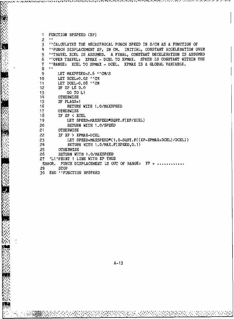
1 FUNCTION RPSPEED (XP)23 "CALCULATES THE RECRIPROCAL PUNCH SPEED IN S/CM AS A FUNCTION OF_4 ''PUNCH DISPLACEMENT XP, IN CM. INITIAL, CONSTANT ACCELERATION OVER"5 "TRAVEL XCEL IS ASSUMED. A FINAL, CONSTANT DECELERATION IS ASSUMED6 "OVER TRAVEL: XPMAX - DCEL TO XPMAX. SPEED IS CONSTANT WITHIN THE7 "'RANGE: XCEL TO XPMAX - DCEL. XPMAX IS A GLOBAL VARIABLE.89 LET MAXSPEED=2.6 ''CM/S10 LET XCEL:O.02 ''CCM11 LET DCEL=O.08 ''CM12 IF XP LE 0.0
- 13 GO TO LI114 OTHERWISE15 IF FLAGU:I16 RETURN WITH 1.O/MAXSPEED17 OTHERWISE18 IF XP < XCEL19 LET SPEED=t4AXSPEED*SQRT.F(XP/XCEL)20 RETURN WITH 1.0/SPEED21 OTHERWISE22 IF XP > XPMAX-DCEL23 LET SPEED=MAXSPEED*( 1. O-SQRT. F((XP-XPMAX+DCEL)/DCEL))24 RETURN WITH 1.O/MAX.F(SPEED,O.1)25 OTHERWISE26 RETURN WITH 1.0/MAXSPEED27 'L1'PRINT 1 LINE WITH XP THUS
ERROR. PUNCH DISPLACEMENT 1S OUT OF RANGE: XP ............29 STOP30 END 'FUNCTION RPSPEED
A-13
½s T
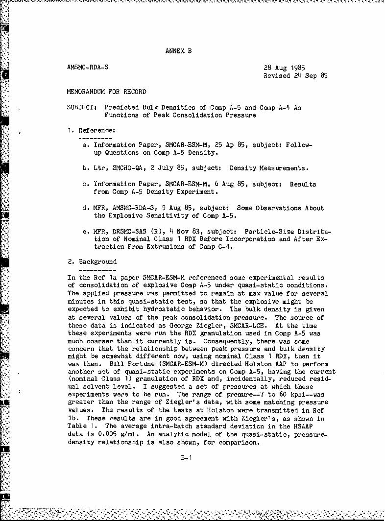
ANNEX B
AMSMC-RDA-S 28 Aug 1985
Revised 24 Sep 85
MEMORANDUM FOR RECORD
SUBJECT: Predicted Bulk Densities of Comp A-5 and Comp A-4 AsFunctions of Peak Consolidation Pressure
1. Reference:
- a. Information Paper, SMCAR-.ESM-M, 25 Ap 85, subject: Follow-up Quest tons on Comp A-5 Density.
b. Ltr, SMCHO-QA, 2 July 85, subject: Density Measurements.
c. Information Paper, SMCAR-ESM-M, 6 Aug 85, subject: Resultsfrom Comp A-5 Density Experiment.
d. MFR, AMSMC-RDA-S, 9 Aug 85, sabject: Some Observations Aboutthe Explosive Sensitivity of Comp A-5.
e. MFR, DRSMC-SAS (R), 4 Nov 83, subject: Particle-Size Distribu-tion of Nominal Class 1 RDX Before Incorporation and After Ex-tracticn From Extrusions of Comp C-4.
2. Background
In the Ref la paper SMCAR-ESM-M referenced some experimental resultsof consolidation of explosive Comp A-5 under quasi-static conditions.The applied pressure ;vas permitted to remain at max value for severalminutes in this quasi-static test, so that the explosive might beexpected to exhibit hydrostatic behavior. The bulk density is givenat several values of the peak consolidation pressure. The source ofthese data is indicated as George Ziegler, SMCAR-LCE. At the timethese experiments were run the RDX granulation used in Comp A-5 wasmuch coarser tLan it currently is. Consequently, there was scmeconcern that the relationship between peak pressure and bulk densitymight be somewhat different now, using nominal Class 1 RDX, than itwas then. Bill Fortune (SMCAR-ESM-M) directed Holston AAP to performanother set of quasi-static experiments on Comp A-5, having the current(nominal Class 1) granulation of RDX and, incidentally, reduced resid-ual solvent level. I suggested a set of pressures at which theseexperiments were to be run. The range of pressre--7 to 60 kpsi--wasgreater than the range of Ziegler's data, with some matching pressurevalues. The results of the tests at Holston were transmitted in Reflb. These results are in good agreement with Ziegler's, as shown inTable 1. The average intra-batch standard deviation in the HSAAPdata is 0.005 g/ml. An analytic model of the quasi-static, pressure-density relationship is also shown, for comparison.
B-I
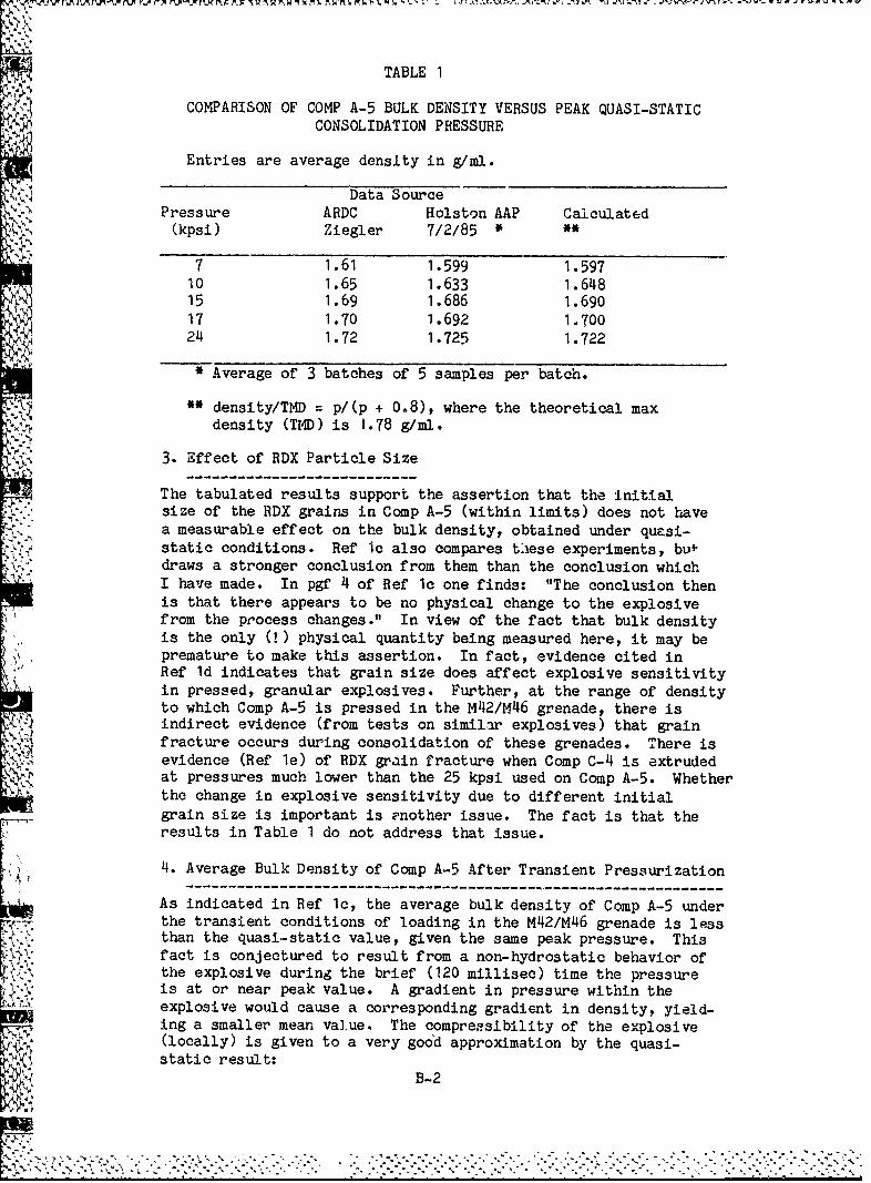
f TABLE 1
COMPARISON OF COMP A-5 BULK DENSITY VERSUS PEAK QUASI-STATICCONSOLIDATION PRESSURE
4 Entries are average density in g/ml.
Data SourcePressure ARDC Holston AAP Calculated
(kpsi) Ziegler 7/2/85 * **
7 1.61 1.599 1.59710 1. 633 1.64815 1.69 1.686 1.69017 1.70 1.692 1.70024 1.72 1.725 1.722
• Average of 3 batches of 5 samples per batch.
" density/TMD : p/(p + 0.8), where the theoretical maxdensity (TMD) is 1.78 g/ml.
3. Effect of RDX Particle Size
The tabulated results support the assertion that the initialsize of the RDX grains in Comp A-5 (within limits) does not havea measurable effect on the bulk density, obtained under quasi-static conditions. Ref Ic also compares these experiments, bu-draws a stronger conclusion from them than the conclusion whichI have made. In pgf 4 of Ref Ic one finds: "The conclusion thenis that there appears to be no physical change to the explosivefrom the process changes." In view of the fact that bulk densityis the only (!) physical quantity being measured here, it may bepremature to make this assertion. In fact, evidence cited inRef Id indicates that grain size does affect explosive sensitivityin pressed, granular explosives. Further, at the range of densityto which Comp A-5 is pressed in the M42/M46 grenade, there is
4J-) indirect evidence (from tests on similar explosives) that grainfracture occurs during consolidation of these grenades. There isevidence (Ref le) of RDX grain fracture when Comp C-4 is extruded
'• at pressures much lower than the 25 kpsi used on Comp A-5. Whetherthe change in explosive sensitivity due to different initialgrain size is important is Pnother issue. The fact is that theresults in Table 1 do not address that issue.K •4. Average Bulk Density of Comp A-5 After Transient Pressurization
-------- ------------------------------------------ I---------------------As indicated in Ref Ic, the average bulk density of Comp A-5 underthe transient conditions of loading in the M42/M46 grenade is lessthan the quasi-static value, given the same peak pressure. This
r fact is conjectured to result from a non-hydrostatic behavior ofthe explosive during the brief (120 millisec) time the pressure
•.lI is at or near peak value. A gradient in pressure within theexplosive would cause a corresponding gradient in density, yield-
ing a smaller mean value. The compressibility of the explosive(locally) is given to a very good approximation by the quasi-static result:
S• B-2
[-7:7 .•- " - ' •- " .- ''' .• °-.,.. ' . ' ",.. ' ' .- " • " .,.• ". " "' , . J . '•-• . ' •" . . •"-' ' . , ','
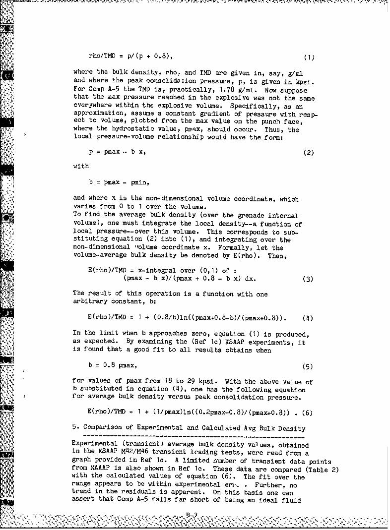
rho/TMD p/(p + 0.8), (1)
where the bulk density, rho7 and TMD are given in, say, g/mland where the peak cosolidaz ion presstu'e, p, is given in kpsi.
.k For Comp A-5 the TMD is, practically, 1.78 g/ml. Now supposethat the max pressure reached in the explosive was not the same
S-: everywhere within the explosive volume. Specifically, as anapproximation, assume a constant gradient of pressure with resp-ect to volume, plotted from the max value on the punch face,where the hydrostatic value, pwax, should occur. Thus, thelocal pressure-volume relationship would have the form:
p = pmax .- b x, (2)
with
b = pmax - pmin,
and where x is the non-dimensional volume coordinate, whichvaries from 0 to 1 over the volume.To find the average bulk density (over the grenade internalvolume), one must integrate the local density--a function oflocal pressure--over this volume. This corresponds to sub-stituting equation (2) into (I), and integrating over thenon..dimensional rolume coordinate x. Formally, let thevolume-average bulk density be denoted by E(rho). Then,
E(rho)/TMD = x-integral over (0,1) of(pmax - b x)/(pmax + 0.8 - b x) dx. (3)
The result of this operation is a function with onearbitrary constant, b:
E(rho)/TMD = 1 + (0. 8 /b)ln((pmax+0.8-b)/(pmax+0.8)). (4)
In the limit when b approaches zero, equation (1) is produced,as expected. By examining the (Ref Ic) KSAAP experiments, itis found that a good fit to all results obtains when
b = 0.8 pmax, (5)
"for values of pmax from 18 to 29 kpsi. With the above value ofI b substituted in equation (4), one has the following equation
for average bulk density versus peak consolidation pressure.
E(rho)/TMD = 1 + (I/pmax)ln((0.2pmax+0.8)/(pmax+0.8)) . (6)
5. Comparison of Experimental and Calculated Avg Bulk Density-------- ----------------------------------------------------------
Experimental (transient) average bulk density values, obtainedKD~ in the KSAAP M42/M46 transient loading tests, were read from agraph provided In Ref 1c. A limited number of transient data pointsfrom MAAAP is also shown in Ref Ic. These data are compared (Table 2)with the calculated values of equation (6). The fit over therange appears to be within experimental er,., . Further, notrend in the residuals is apparent. On this basis one canassert that Comp A-5 falls far short of being an ideal fluid
IN~ 2 .
during transient consolidation. A portion of the explosive"volume may experience an effective pressure which is only 20 %of pmax in terms of its comp'essible response.
TABLE 2
COMPARISON OF EXPERIMENTAL AND THEORETICAL AVERAGE BULKDENSITIES OF COMP A-5 AFTER M42/M46 GRENADE LOADING
Peak Pressure Average Density (g/ml)(kpsi) Exp (KSAAP) Exp (MAAAP) Calculated
VE 81/82 July 1985 Transient Quasi-static *
8 1.500 1.1491 1.618
12 1.550 1.574 1.66914 1.600 1.600 1.68418 1.640 1.636 1.70419 1.645 1.643 1.70820 1.642 1.649 1.71221 1.657 1.655 1.71522 1.666 1.660 1.71823 1.667 1.650 1.665 1.72024 1.675 1.670 1.72225 1.676 1.674 1.72526 1.679 1.678 1.72727 1.682 1.681 1.72928 1.685 1.684 1.73029 1.694 1.687 1.73230 1.690 1.734
* The quasi-static value, 1.7 8 p/(p + 0.8), is offered for comparison.
6. Quasi-static Bulk Density of Comp A-4
It is noted that equation (1), which is used to cs',culate thequasi-static density of Comp A-5, is written in a non-dimensionalform. Both sides of this equation are ratios of dimensionalquantities. The only dimensional parameter which relates tocompressibility of the explosive is the constant 0.8 kpsi. If
- this constant is essentially the same for Comp A-5 and Comp A-4,the quasi-static bulk density of Comp A-4 can be calculated from (1)using the TMD z 1.76 g/ml. This density is based on a formulation
of Comp A-4 that has an addition of 3.0 % wax to RDX. The assumeddensity of wax is 0.91 to 0.92 g/ml. Since the formulation of CompA-4 may vary slightly in percent wax, one should recalculate theTMD if the actual formulation is much different from that assumed.Variation in the TMD of A-4 is also contributed by different waxes.The bulk density values for Comp A-4 shown in Table 3. Comparablevalues of Comp A-5 are shown for comparison.
B-4I
S_------------..
TABLE 3
COMPARISON OF BULK DENSITIES OF COMP A-5 AND COMP A-4VERSUS PEAK QUASI-STATIC CONSOLIDATION PRESSURE
Entries are calculated bulk densities in g/ml.
Pressure Explosive Composition(kpsi) A-5 A-4 with TMD of:
1.760 1.770
7 1.597 1.578 1.5888 1.618 1.599 1.6099 1.635 1.616 1.626
10 1.648 1.628 1.63915 1.690 1.670 1.680
17 1.700 1.680 1.69020 1.712 1.692 1.70224 1.722 1.702 1.713"40 1.745 1.724 1.73560 1.757 1.736 1.747
7. Conclusions and Recommendations
,Mathematical models for the bulk density of Comp A-5 andComp A-4 have been presented here. Under quasi-static press-urization the equation which relates bulk density to peak pressurehas a very simple form. However, this result is shown to matchexperimental values of bulk density for Comp A-5 over the range"of pressure from 7 kpsi to 60 kpsi. When the loading conditionon the explosive is rather transient, with near-peak load persist-
'- ~ ing for only 120 milliseconds, the explosive does not have time"to react in a hydrostatic manner. It has been shown that theaverage bulk density of the explosive in M42/M46 grenades issignificantly lower than the quasi-static value obtained for agiven pressure. A formula for the average bulk density, aftertransient loading, is derived here. This fc iula fits experimental
7. results over the entire experimental pressure range for Comp A-5.A similar formula may be derived for Comp A-4, given some inform-ation about the nature of the pressure gradient which existswithin the explosive during pressurization. Of course, the sameassumption could be made for Comp A-4 as was made for Comp A-5.I have been reluctant to do this, since there is a large dis-K:." parity in the portion binder in these two explosives. Comp A-5has about half as much binder as Comp A-4. In the quasi-staticcase, the compressible behavior of these explosives is predictedto be much the same, relative to their respective TMDs. In theinterest of expanding engineering knowledge, it is recommendedthat: (a) the bulk density predictions of Table 3 for Comp A-4"be verified empirically (as was done for Comp A-5), afterquasi-static loading, and (b) the average density of explosivein M42 grenades be measured after transient loading using Comp A-4.Resources permitting, it would also be desirable to measure thelocal bulk density within the HE in M42 grenades at severallocations. These data would support the assumption tnat the
r.• .jB - 5
"•, • -s L - . , ~*.2 ~_1 - t .• W1 ý_ 0- - •_7 C1 o It •-,-- ;¥. . = •-' '-W W••Arr 1 FT A I a1 Z-L' 4 '-
TABLE 3
COMPARISON OF BULK DENSITIES OF COMP A-5 AND COMP A-4VERSUS PEAK QUASI-STATIC CONSOLIDATION PRESSURE
Entries are calculated bulk densities in g/ml.
Pressure Explosive Composition
(kpsi) A-5 A-4 with TMD of:1.760 1.770
7 1.597 1.578 1.5888 1.618 1.599 1.6099 1.635 1.616 1.626
10 1.648 1.628 1.63915 1.690 1.670 1.68017 1.700 1.680 1.69020 1.712 1.692 1.70224 1.722 l.-(02 1.71340 1.745 1.724 1.73560 1.757 1.736 1.747
7. Conclusions and Recommendations
Mathematical models for the bulk density of Comp A-5 andComp A-4 have been presented here. Under quasi-static press-
urization the equation which relates bulk density to peak pressurehas a very simple form. However, this result is shown to matchexperimental values of bulk density for Comp A-5 over the rangeof pressure from 7 kpsi to 60 kpsi. When the loading conditionon the explosive is rather transient, with near-peak load persist-ing for only 120 milliseconds, the explosive does not have time"to react in a hydrostatic manner. It has been shown that theaverage bulk density of the explosive in M42/M46 grenades issignificantly lower than the quasi-static value obtained for agiven pressure. A formula for the average bulk density, aftertransient loading, is derived here. This formula fits experimentalresults over the entire experimental pressure range for Comp A-5.A similar formula may be derived for Comp A-4, given some inform-ation about the nature of the pressure gradient which existswithin the explosive during pressurization. Of course, the same"assumption could be made for Comp A-4 as was made for Comp A-5.I have been reluctant to do this, since there is a large dis-parity in the portion binder in these two explosives. Comp A-5has about half as much binder as Comp A-4. In the quasi-staticcase, the compressible behavior of these explosives is predictedto be much the same, relative to their respective TMDs. In theinterest of expanding engineering knowledge, it is recommendedthat: (a) the bulk density predictions of Table 3 for Comp A-4be verified empirically (as was done for Comp A-5), afterquasi-static loading, and (b) the average density of explosivein M42 grenades be measured after transient loading using Comp A-4.Resources permitting, it would also be desirable to measure thelocal bulk density within the HE in M42 grenades at severallocations. These data would support the assumption that the
B-5
W~.7 ru ;~ -- Y -_v ~ IX 2-j I;'.F.P IJ 'Z~ IJC~JP ýZ W~l '.T'. I1 I -- II;--
effective pressure exhibits a constant gradient within the HEvolume. Local densities should be measured at three locations onthe grenade axis, from the cone to the inside of the cap (dome).Also, at a midaxial station, three local radial positions shouldbe sampled for bulk density at different polar angles.
GEORGE SCHLENKER
Operations Research Analyst
AMSMC-RDA-S
B-6
%. i9- - . - __-___