Embed Size (px)
Citation preview
© Siemens AG 2012© Siemens AG 2011Energy Sector
V Hild, D Retzmann, M Schmidt M Luther D. PovhSiemens AG FAU – Uninersity of Erlangen Chief ConsultantErlangen Nuremberg Chairman, IEC TC 115
Simulation of Transients with HVDC and FACTS in large AC systems – Benefits of Power Electronics
Presented by Rajat Majumder, SIEMENS Energy Inc
© Siemens AG 2012Power Transmission Solutions
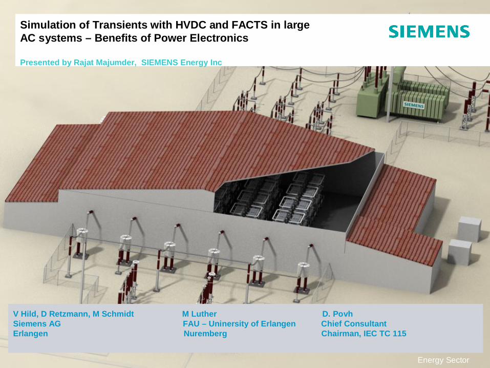
Planning of Grid Extensions
Feasibility Studies forAC & DC Technologies
Power System Control Energy Management
Load Flow Analysis
System Optimization
Grid Fault Analysis
System Protection –Relay Testing
Controls & Protectionfor AC & DC Systems
Objectives of Power System Simulation …
22
E T PS S/Re
01-2012 E T PS S/Re01-2012
… the Task defines the Tool
© Siemens AG 20123 Power Transmission SolutionsE T PS S/Re
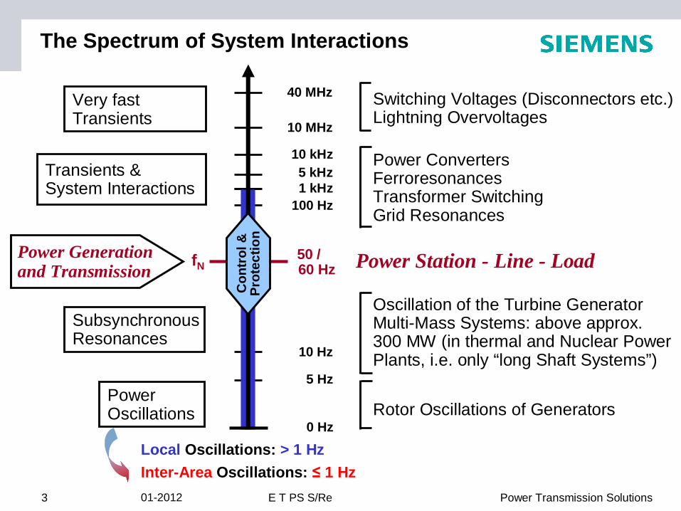
The Spectrum of System Interactions
PowerOscillations Rotor Oscillations of Generators
5 Hz
0 Hz
SubsynchronousResonances
Oscillation of the Turbine Generator Multi-Mass Systems: above approx. 300 MW (in thermal and Nuclear Power Plants, i.e. only “long Shaft Systems”)10 Hz
Very fast Transients
Switching Voltages (Disconnectors etc.)Lightning Overvoltages
40 MHz
10 MHz
Local Oscillations: > 1 HzInter-Area Oscillations: 1 Hz
Power Station - Line - Load50 / 60 HzfN
Power Generationand Transmission
5 kHzTransients &System Interactions
Power ConvertersFerroresonancesTransformer SwitchingGrid Resonances
1 kHz100 Hz
10 kHz
Con
trol
&
Prot
ectio
n
01-2012
© Siemens AG 2012
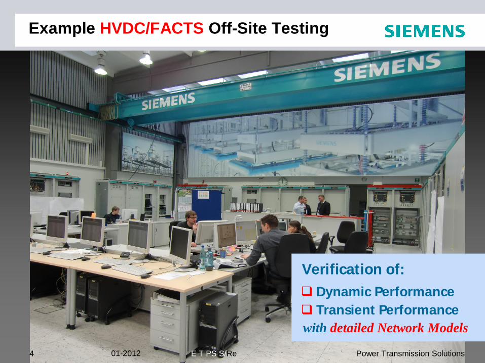
Example HVDC/FACTS Off-Site Testing
Verification of:
Dynamic PerformanceTransient Performance
with detailed Network Models
4 Power Transmission SolutionsE T PS S/Re01-2012
© Siemens AG 20125 Power Transmission SolutionsE T PS S/Re
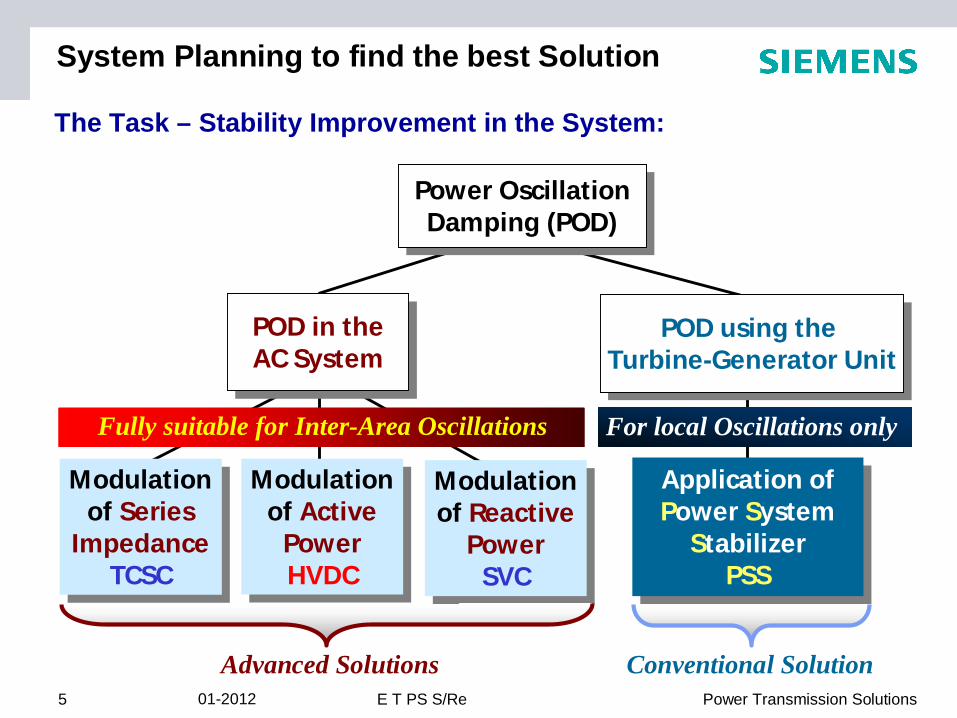
The Task – Stability Improvement in the System:
Modulation of Series
ImpedanceTCSC
Modulation of Series
ImpedanceTCSC
Modulation of Active
PowerHVDC
Modulation of Active
PowerHVDC
Modulation of Reactive
PowerSVC
Modulation of Reactive
PowerSVC
POD in theAC System
POD in theAC System
Advanced Solutions Conventional Solution
Fully suitable for Inter-Area Oscillations
Application ofPower System
Stabilizer PSS
Application ofPower System
Stabilizer PSS
POD using the Turbine-Generator Unit
POD using the Turbine-Generator Unit
For local Oscillations only
Power OscillationDamping (POD)
Power OscillationDamping (POD)
System Planning to find the best Solution
01-2012
© Siemens AG 2012
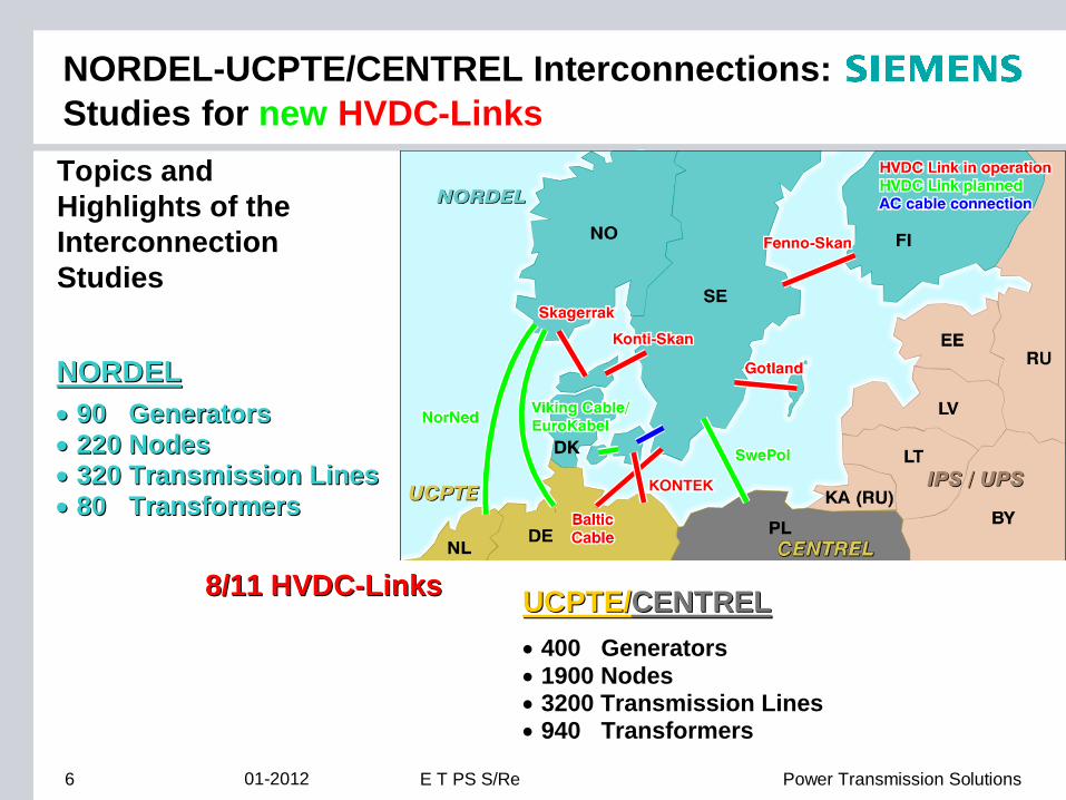
NORDEL-UCPTE/CENTREL Interconnections:Studies for new HVDC-Links
6 Power Transmission SolutionsE T PS S/Re
Topics andHighlights of the InterconnectionStudies
90 Generators90 Generators220 Nodes220 Nodes320 Transmission Lines320 Transmission Lines80 Transformers80 Transformers
NORDELNORDEL
8/11 8/11 HVDCHVDC--LinksLinks UCPTE/UCPTE/CENTRELCENTREL400 Generators400 Generators1900 Nodes1900 Nodes3200 Transmission Lines3200 Transmission Lines940 Transformers940 Transformers
01-2012
© Siemens AG 2012
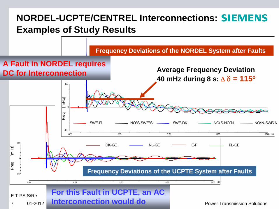
NORDEL-UCPTE/CENTREL Interconnections: Examples of Study Results
0.00 6.25 12.50 18.75 25.00 SEC
-100
0
100
Freq
[mH
z]
DK-GE NL-GE E-F PL-GE
Frequency Deviations of the UCPTE System after Faults
DK-GE NL-GE E-F PL-GE
Fre
q
[mH
z]
-100
0
100
SWE-FI NO/S-SWE/S SWE-DK NO/S-NO/N NO/N-SWE/N
0.00 6.25 12.50 18.75 25.00 SEC
Average Frequency Deviation 40 mHz during 8 s: = 115o
Frequency Deviations of the NORDEL System after Faults
SWE-FI NO/S-SWE/S SWE-DK NO/S-NO/N NO/N-SWE/N
A Fault in NORDEL requires DC for Interconnection
7 Power Transmission SolutionsE T PS S/Re01-2012
For this Fault in UCPTE, an AC Interconnection would do77
E T PS S/Re
01-2012
© Siemens AG 2012
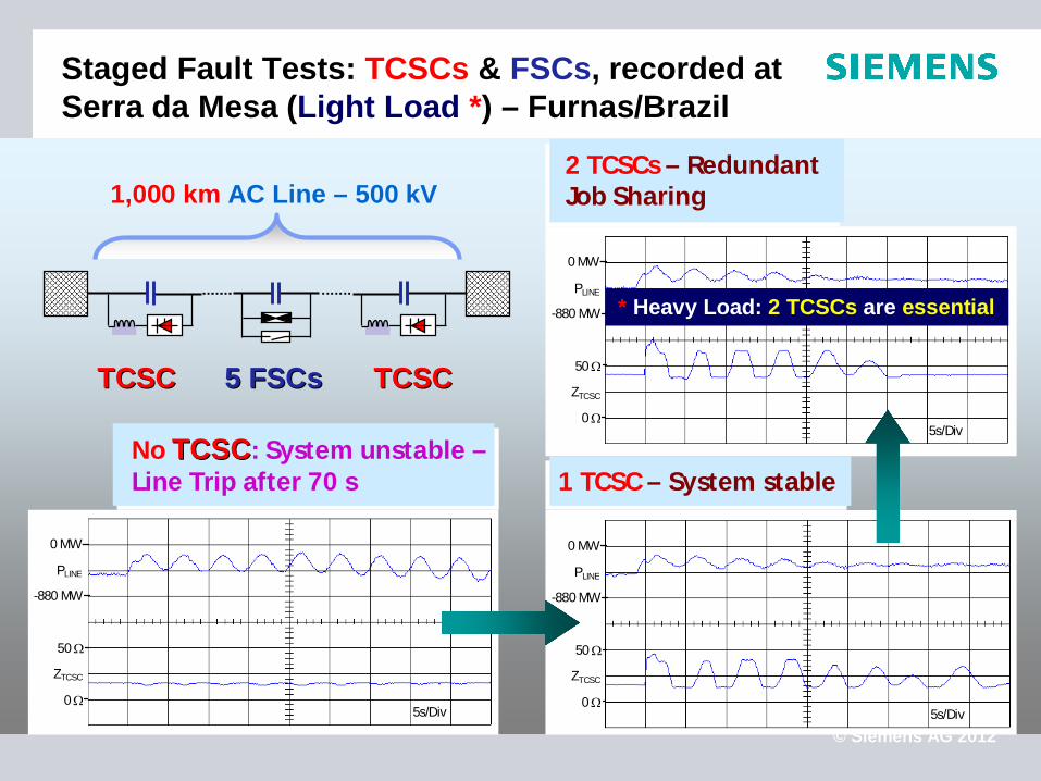
Staged Fault Tests: TCSCs & FSCs, recorded at Serra da Mesa (Light Load *) – Furnas/Brazil
PLINE
0 MW
-880 MW
0
50
ZTCSC
5s/Div
5 FSCs 5 FSCs
PLINE
0 MW
-880 MW
0
50
ZTCSC
5s/Div
PLINE
0 MW
-880 MW
0
50
ZTCSC
5s/Div
No TCSCTCSC: System unstable –Line Trip after 70 s 1 TCSC – System stable
2 TCSCs – Redundant Job Sharing1,000 km AC Line – 500 kV
* Heavy Load: 2 TCSCs are essential
TCSCTCSC TCSCTCSC
© Siemens AG 2012
GuiyangNayong
AnshunAnshun
Huishui
Hechi
Lubuge
TSQ-ILuoping
HVDC TSQ
LiudongYantan
TCSC & FSCPingguo
Baise
TSQ-II
Nanning
Yulin
Laibin
Hezhou
Gaomin
Luodong
ZhaoqingConv. Stat.
Beijiao Conv. Stat.
Guangzhou
Wuzhou
TSQ Conv. Stat.
Yunnan
Guangxi
Guizhou
Guangdong
HVDC GuiGuang
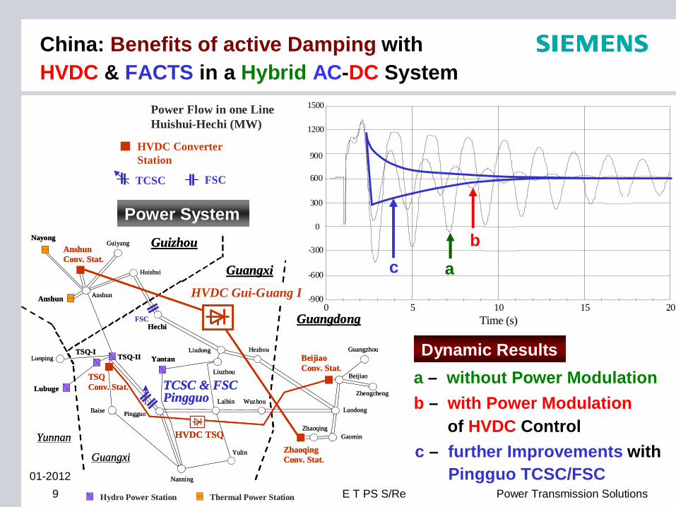
a – without Power Modulationb – with Power Modulation
of HVDC Controlc – further Improvements with
Pingguo TCSC/FSC
Power Flow in one Line Huishui-Hechi (MW)
Anshun Conv. Stat.
Liuzhou
Zhaoqing
Beijiao
Zhengcheng
Guangxi
Pingguo
FSC
GuiyangNayong
AnshunAnshun
Huishui
Hechi
Lubuge
TSQ-ILuoping
HVDC TSQ
LiudongYantan
TCSC & FSCPingguo
Baise
TSQ-II
Nanning
Yulin
Laibin
Hezhou
Gaomin
Luodong
ZhaoqingConv. Stat.
Beijiao Conv. Stat.
Guangzhou
Wuzhou
TSQ Conv. Stat.
Yunnan
Guangxi
Guizhou
Guangdong
HVDC Gui-Guang I
Anshun Conv. Stat.
Liuzhou
Hydro Power Station Thermal Power Station
Zhaoqing
Beijiao
Zhengcheng
Guangxi
Pingguo
FSC
Power System
5 10 15 200
0
600
900
1200
1500
-600
300
-900
-300
Time (s)
Powe
r flo
w in
one
line
Huish
ui-H
echi
(MVA
)
a
b
ab
c
Dynamic Results
9 Power Transmission Solutions
HVDC Converter Station
TCSC FSC
E T PS S/Re01-2012
China: Benefits of active Damping with HVDC & FACTS in a Hybrid AC-DC System
© Siemens AG 201210 Power Transmission SolutionsE T PS S/Re
2b)
2a)
1a)
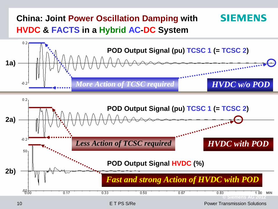
POD Output Signal (pu) TCSC 1 (= TCSC 2)
POD Output Signal (pu) TCSC 1 (= TCSC 2)
POD Output Signal HVDC (%)
Fast and strong Action of HVDC with POD
HVDC w/o PODMore Action of TCSC required
Less Action of TCSC required HVDC with POD
China: Joint Power Oscillation Damping withHVDC & FACTS in a Hybrid AC-DC System
© Siemens AG 201211 Power Transmission Solutions
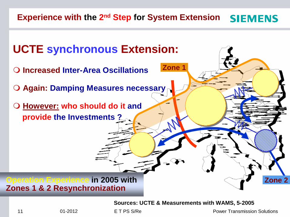
Operation Experience in 2005 withZones 1 & 2 Resynchronization
Sources: UCTE & Measurements with WAMS, 5-2005
UCTE synchronous Extension:
Increased Inter-Area Oscillations
Again: Damping Measures necessary
However: who should do it andprovide the Investments ?
Zone 1
Zone 2
Experience with the 2nd Step for System Extension
E T PS S/Re01-2012
© Siemens AG 2012Source: UCTE-IPS/UPS Study – Presentation
Dr. Matthias Luther at FAU Erlangen,Dec. 15, 200912 Power Transmission SolutionsE T PS S/Re01-2012
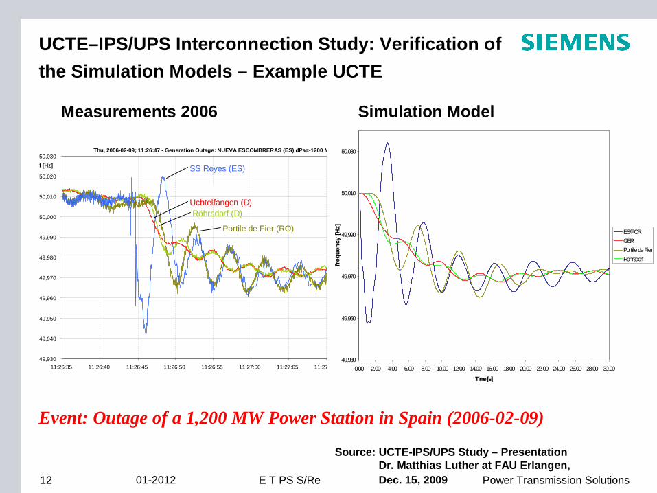
UCTE–IPS/UPS Interconnection Study: Verification of the Simulation Models – Example UCTE
Measurements 2006 Simulation Model
Thu, 2006-02-09; 11:26:47 - Generation Outage: NUEVA ESCOMBRERAS (ES) dPa=-1200 MW
49,930
49,940
49,950
49,960
49,970
49,980
49,990
50,000
50,010
50,020
50,030
11:26:35 11:26:40 11:26:45 11:26:50 11:26:55 11:27:00 11:27:05 11:27:10 11:27:15 11:27:20
f [Hz]
Portile de Fier (RO)
SS Reyes (ES)
Uchtelfangen (D) Röhrsdorf (D)
49,930
49,950
49,970
49,990
50,010
50,030
0,00 2,00 4,00 6,00 8,00 10,00 12,00 14,00 16,00 18,00 20,00 22,00 24,00 26,00 28,00 30,00
Time [s]
freq
uenc
y [H
z]
ES/PORGERPortile de FierRöhrsdorf
Event: Outage of a 1,200 MW Power Station in Spain (2006-02-09)
© Siemens AG 2012
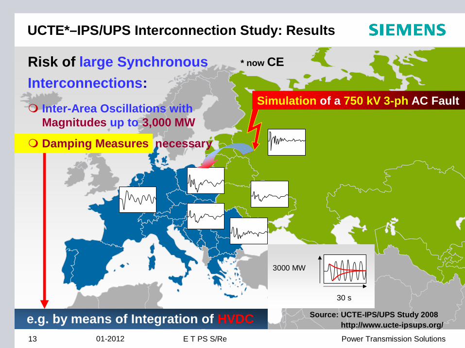
UCTE*–IPS/UPS Interconnection Study: Results
3000 MW
30 s
Simulation of a 750 kV 3-ph AC Fault
* now CE
e.g. by means of Integration of HVDC
Risk of large Synchronous Interconnections:
Inter-Area Oscillations withMagnitudes up to 3,000 MW
Damping Measures necessary
13 Power Transmission SolutionsE T PS S/Re01-2012
Source: UCTE-IPS/UPS Study 2008 http://www.ucte-ipsups.org/
© Siemens AG 201214 Power Transmission SolutionsE T PS S/Re
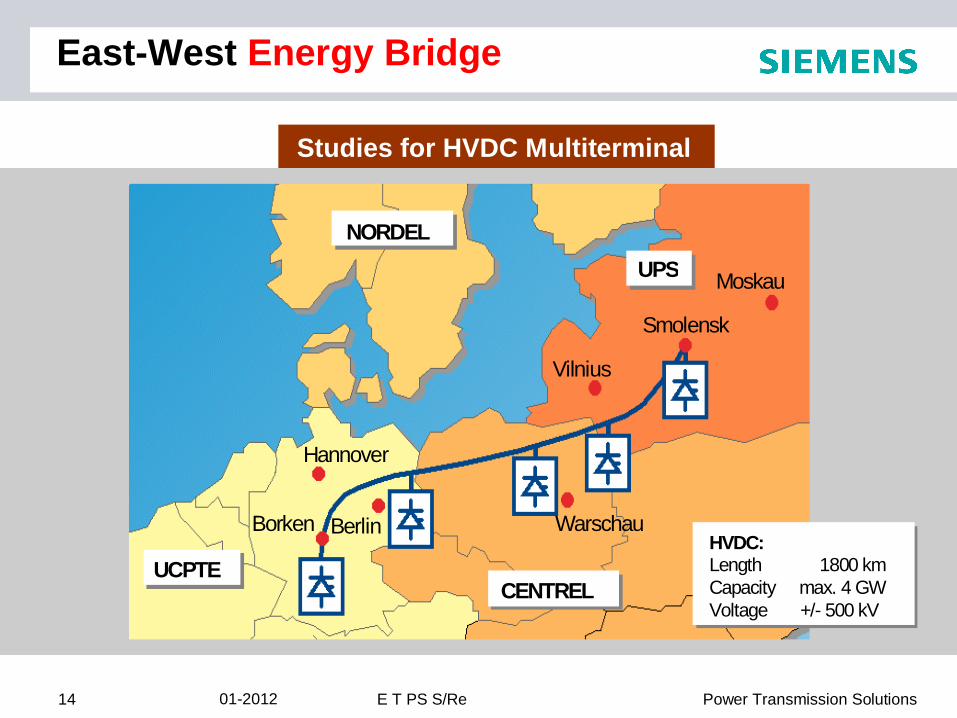
NORDEL
Smolensk
Hannover
Moskau
BerlinBorken Warschau
Vilnius
UPS
UCPTECENTREL
HVDC:Length 1800 kmCapacity max. 4 GWVoltage +/- 500 kV
Studies for HVDC Multiterminal
East-West Energy Bridge
01-2012