Embed Size (px)
Citation preview
8/3/2019 Simulation Symmetric N-dimensional Cube Network-on-Chip Architecture by Using Ns-2
http://slidepdf.com/reader/full/simulation-symmetric-n-dimensional-cube-network-on-chip-architecture-by-using 1/7
Simulation Symmetric N-dimensional CubeNetwork-on-Chip Architecture by Using Ns-2
Reza Kourdy
Department of Computer Engineering
Islamic Azad University,
Khorramabad Branch, Iran
Mohammad Reza Nouri rad
Department of Computer Engineering
Islamic Azad University,
Khorramabad Branch, Iran
Abstract — The symmetric recursive structure of the network-on-chip architecture has played an important role in developing
parallel processing and is still popular and influential. The symmetric recursive structure of the hypercube support various
elegant and efficient parallel algorithms that often serve as starting points for developing, or benchmarks for evaluating,
algorithms on other architectures. This paper describes the design and simulation N-dimensional network-on-chip by recursive
structure. We use network simulator NS-2 modeling and simulating NoC at high-level chip design and the different dimensions
2 to 6 (2D to 6D) has simulated.
Index Terms —Network-on-Chip (NoC), network simulator NS-2, cube-connected cycles (CCC), recursive structure, hypercube.
1 INTRODUCTION
oore's law predicts that by 2008, it will be possibleto integrate over a billion transistors on a singlechip. Current core based on SOC methodologies
will not respond to the needs of the billion transistor era.Network on Chip (NOC), a new chip design paradigmconcurrently proposed by many research groups[1],[2],[3]is expected to be an important architectural choice forfuture SOCs. The proposed NOC architectures offer ageneral but fixed communication platform which can be
reused for a large number of SOC designs.Technology scaling is causing the energy consumption ofthe on-chip network to become increasingly importantdesign criteria. The goal of macro networks is to maxim-ize performance without regard for energy consumption,especially for large scale parallel computers wherethroughput and latency are of primary importance. Ittherefore stands to reason that a straightforward adapta-tion of macro network implementations for network-on-chip is not appropriate. The problem faced by chip de-signers is that the design criteria run contrary to oneanother:• Minimizing the energy consumption and maximizing
performance are usually conflicting goals.• Increased reliability usually means higher complexity,which results in larger area, degraded performance, andhigher energy consumption.
Therefore, designing a NoC interconnect requiressearching through a vast multidimensional design space.There are many design parameters that can affect systemperformance and cost, but the design decision that has thelargest impact is the choice of topology. The remainder ofthis section will briefly discuss the basic network topolo-gies that other topologies are derived from. [4]
Chip integration has reached a stage where a completesystem can be placed on a single chip. The integration has
been made possible because of the rapid developments inthe field of VLSI design. These chips, commonly termedas System on a chip (SoC), are primarily used in embed-ded systems. While designing an SoC, a vendor may use alibrary of cores designed by external designers in addi-tion to using cores from in-house libraries. Cores are basi-cally predesigned models of complex functions termed asIntellectual Property Blocks (IP Blocks), Virtual Compo-nents (VC) or simply micros. One key issue in the SoC
design is heterogeneity; components of various vendorswith significantly distinct characteristics lie on the samechip, making the design process even more complex [5].
A NoC has been proposed as a viable alternative forthe inefficient buses of today’s SoCs. A NoC is viewed asa collection of computational resources connectedthrough a network where they communicate using pack-ets. [6]
2 RECURSIVE STRUCTURE
Let S be a structure. Then:(a) S is called a recursive structure, if there is a repre-
sentationδ
of S, which admits a recursive extension, aswell as a recursive right inverse operation over S,(b) S is called a strongly recursive structure, if there is a
representation δ of S which is a recursive retraction overS.
In these cases S is also called recursive via or stronglyrecursive via δ, respectively.
By the following proposition δ = [δ 1; …; δ n] is a re-cursive retraction over a natural structure S, if δ 1; …; δ nare. [7]
M
JOURNAL OF COMPUTING, VOLUME 4, ISSUE 1, JANUARY 2012, ISSN 2151-9617
https://sites.google.com/site/journalofcomputing
WW.JOURNALOFCOMPUTING.ORG 71
8/3/2019 Simulation Symmetric N-dimensional Cube Network-on-Chip Architecture by Using Ns-2
http://slidepdf.com/reader/full/simulation-symmetric-n-dimensional-cube-network-on-chip-architecture-by-using 2/7
3 NETWORK ARCHITECTURE
The NoC architecture is composed of tiles and communi-cation links. Each tile consists of an intellectual property(IP) core, a network interface (NI), and a switch. Theswitches are interconnected by physical links. The net-work interface component decouples the core from thenetwork. The switch implements the routing strategy
needed to transmit data from one core to another. Acommon simplification is to combine all three compo-nents and to refer to them simply as a node (or tile) on theNoC.
3.1 Network Topologies
The network architecture, or topology, describes thephysical organization of the interconnections network. Anetwork topology can be classified as being either director indirect. A node in a network can be a terminal node,which acts as a source and sink for data, a switch thatroutes data, or both. In a direct network, every node actsas a terminal node. In an indirect network, a node is ei-
ther a terminal or a switch node.A direct network can be redrawn as indirect by redraw-ing each node as two nodes and showing the switch andterminal nodes separately. Designers of large-scale SoCsmust be aware of the advantages and disadvantages ofeach architecture in order to select an appropriate candi-date for their implementations. The metrics that are ofinterest can be broadly categorized as [8]:• Performance (latency, throughput, cross-section band-width),• Energy consumption• Reliability (error detection and/or correction)• Scalability
• Implementation cost (area).
3.2 Mesh and Torus Topologies
Many topologies have been proposed for NoCs includinga 2D mesh [9], a fat tree [10], and a honeycomb [11].However, most common proposals of all is a 2D meshdue to its simplicity and easiness in implementation.A torus is described as a k-ary n-cube, where n is thenumber of dimensions of the torus, k is the number ofnodes in each dimension, and the total number of nodesis N = kn. The simplest torus topology is a single ring, ork-ary 1-cube, as shown in Figure 2.8a. The most wellknown example of a ring-based network topology is the
token ring [12], which was developed in the late 1970s.Ring networks possess several characteristics that makethem well suited for on-chip implementation [13]:• They have regular physical arrangements that makethem well suited for on-chip layout.• At low dimensions, the physical wires between neigh-bouring switches are short, allowing high speed opera-tion and low energy usage.• For local communication patterns, they exhibit low la-tency and high throughput.• Depending on the architecture, tori have high path di-versity.Arbitrary dimensions of the torus and mesh can be con-
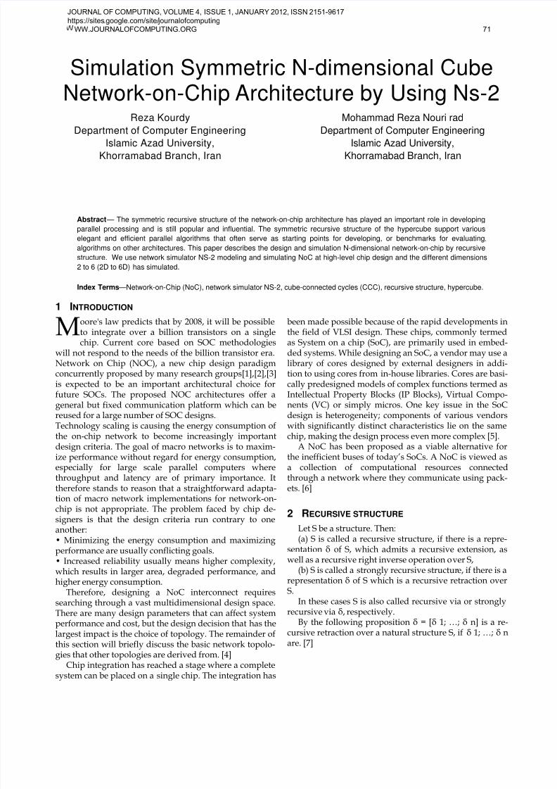
structed by iteratively adding dimensions. The two-dimensional mesh can be constructed by connecting three3-ary 1-meshes. Going one step further, a three dimen-sional mesh network, or cube, can be constructed by con-necting three 3-ary 2-meshes, as shown in Figure 1. Whileit is tempting to use the three dimensional cube (and per-haps higher dimensioned tori/meshes) because of thehigh bisection bandwidth and increased path-diversity,one needs to consider some of the costs associated withsuch a topology. The higher degree switches will be larg-er due to an increased number of buffers and complexity,thus requiring more area and power. Furthermore, three-dimensional topologies must be mapped onto a two-dimensional surface for chip fabrication, and so the wir-ing complexity may result in longer wires and larger arearequirements. For these reasons, lower dimensioned to-pologies that can be easily mapped to a two-dimensionalspace are largely preferred by the NoC research commu-nity. [14]
3.3 Cube-connected cycles (CCC) Topology
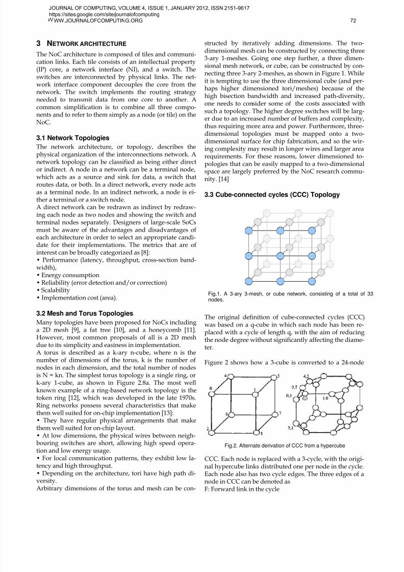
The original definition of cube-connected cycles (CCC)was based on a q-cube in which each node has been re-placed with a cycle of length q, with the aim of reducingthe node degree without significantly affecting the diame-ter.
Figure 2 shows how a 3-cube is converted to a 24-node
CCC. Each node is replaced with a 3-cycle, with the origi-nal hypercube links distributed one per node in the cycle.Each node also has two cycle edges. The three edges of anode in CCC can be denoted asF: Forward link in the cycle
Fig.2. Alternate derivation of CCC from a hypercube
Fig.1. A 3-ary 3-mesh, or cube network, consisting of a total of 33
nodes.
JOURNAL OF COMPUTING, VOLUME 4, ISSUE 1, JANUARY 2012, ISSN 2151-9617
https://sites.google.com/site/journalofcomputing
WW.JOURNALOFCOMPUTING.ORG 72
8/3/2019 Simulation Symmetric N-dimensional Cube Network-on-Chip Architecture by Using Ns-2
http://slidepdf.com/reader/full/simulation-symmetric-n-dimensional-cube-network-on-chip-architecture-by-using 3/7
B: Backward link in the cycleC: Intercycle or cube link
Each node can be identified by a pair (x, y) of integers,where x is the cycle number (the node number in the orig-inal hypercube) and y is the node number within thecycle.
The bisection bandwidth and path diversity of higherdimensioned topologies, such as the 3-ary 3-mesh shownin Figure 1, makes them ideal for interconnecting a largenumber of cores. However, the high node degree andwiring complexity makes them expensive in terms of areaand power for on-chip implementation. The problem hasto do with mapping a three (and higher) dimensionalstructure to a two-dimensional surface.The cube-connected cycles (CCC) [15] topology is a subs-titute for the n–mesh network that uses interconnectedrings to reproduce the structure of a higher dimensionedmesh while using switches of fixed node degree. Figure 2shows an example of the CCC topology where multiplerings are connected such that a k-ary 3-mesh topology isreproduced. The CCC topology has the following proper-ties [15]:• The node degree of all switches is 3.• Processing time is not significantly increased with re-spect to that achievable by the k-ary 3-mesh (3-dimensional hypercube).• The structure is more easily mapped to a two-dimensional surface for on chip implementation.A directed cube-connected cycles DCCC topology [16]that uses unidirectional links has been shown to be evenmore layout efficient than the normal CCC topology. Anexpress cube is a k-ary n-cube network augmented byexpress channels that reduce the path lengths for non-
local messages [17]. The express channels can be insertedinto an existing network without changing the implemen-tation of the switches. Figure 3 shows a network that hasbeen augmented by two levels of express channels, wherethe highest level bypasses the largest number of nodes. Ahierarchical express cube has the locality of a torus and adiameter approaching that of a fully connected network[18]. The drawback of express channels is that the re-quired number of channels increases with the dimension,leading to a larger area overhead associated with the ex-tra routers and links.As special cases of m-ary q-cubes, hypercubes are alsocalled binary q-cubes, or simply q-cubes, where q indi-
cates the number of dimensions. We will use the termhypercube to refer to a generic architecture of this typeand q-cube (particularly, 3-cube, 4-cube, and so forth)when the number of dimensions is relevant to the discus-sion. A q-dimensional binary hypercube (q-cube) is de-fined recursively as follows:• A 1-cube consists of two nodes, labeled 0 and 1, with alink connecting them.• A q-cube consists of two (q–1)-cubes, with the nodeslabeled by preceding the original
Node labels of the two subcubes with 0 and 1, respective-ly, and connecting each node with the label 0x to the node
with the label 1x. The two (q –1)-cubes forming the q-cubeare known as its 0 and 1 subcubes.If the label of a node x (its binary ID) is xq–1 xq–2 ... x2x1x0,then its q neighbors arexq–1 xq–2 ... x2 x1 x'0 neighbor along Dimension 0; denotedby N0(x)xq–1 xq–2 ... x2 x'1 x0 neighbor along Dimension 1 or N1(x)...x'q–1 xq–2 ... x2x1x0 neighbor along Dimension q–1 or Nq–1(x)
In other words, the labels of any two neighboring nodesdiffer in exactly 1 bit. Two nodes whose labels differ in kbits (have a Hamming distance of k ) are connected by ashortest path of length k.Hypercubes are both node- and edge-symmetric, mean-ing that the roles of any two nodes (edges) can be inter-changed with proper relabeling of the nodes. Swappingthe leftmost 2 bits in every node label of a q-cube inter-changes the roles of dimensions q-1 and q-2. As a result, 0and 1 sub cubes can be defined for each of the q dimen-
sions of a q-cube. Complementing a particular bit positionin all node labels results in a relabeling of the nodes thatswitches the roles of the 0 and 1 sub cubes associated withthat dimension A node label x can be transformed to adifferent node label y with k such complementation steps,where k is the Hamming distance between x and y. Simi-larly, swapping bit positions i and j in all node labels in-terchanges the roles of Dimension-i and Dimension-jlinks. Thus, the designations “Dimension 0,” “Dimension1,” and so forth are arbitrary and no inherent order existsamong the various dimensions.Hypercubes have many interesting topological properties,some of which will be explored in the remainder of this
chapter and the end-of-chapter problems. The recursivestructure of hypercubes makes them ideal for runningrecursive or divide-and-conquer type algorithms. Theresults of sub problems solved on the two (q–1)-dimensional subcubes of a q-cube can often be mergedquickly in view of the one-to-one connectivity (matching)between the two subcubes. Multiple node-disjoint andedge-disjoint paths exist between many pairs of nodes ina hypercube, making it relatively easy to develop routingand other parallel algorithms that are tolerant of node oredge failures. A large MIMD-type hypercube machine canbe shared by multiple applications, each of which uses asuitably sized subcube or partition.
3.4 PYRAMID
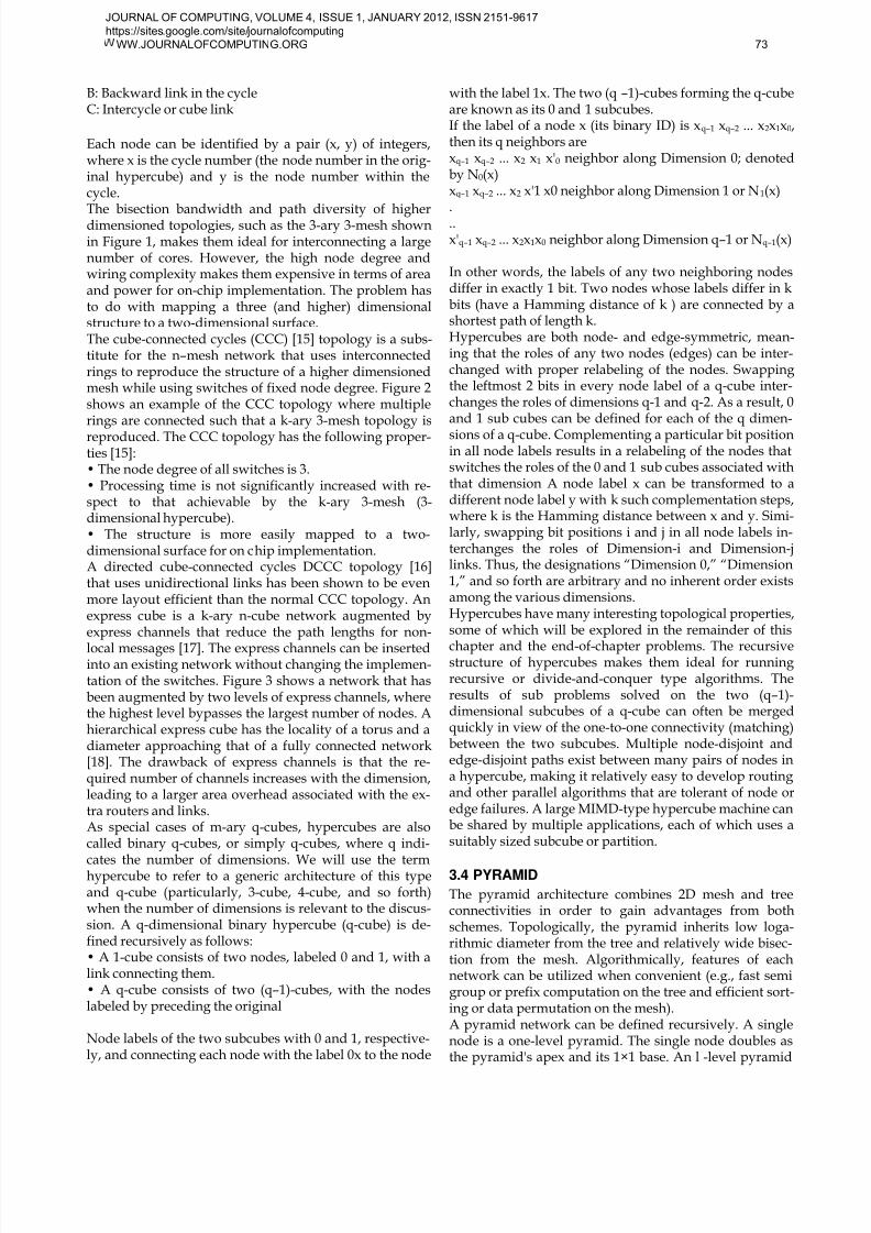
The pyramid architecture combines 2D mesh and treeconnectivities in order to gain advantages from bothschemes. Topologically, the pyramid inherits low loga-rithmic diameter from the tree and relatively wide bisec-tion from the mesh. Algorithmically, features of eachnetwork can be utilized when convenient (e.g., fast semigroup or prefix computation on the tree and efficient sort-ing or data permutation on the mesh).A pyramid network can be defined recursively. A singlenode is a one-level pyramid. The single node doubles asthe pyramid's apex and its 1×1 base. An l -level pyramid
JOURNAL OF COMPUTING, VOLUME 4, ISSUE 1, JANUARY 2012, ISSN 2151-9617
https://sites.google.com/site/journalofcomputing
WW.JOURNALOFCOMPUTING.ORG 73
8/3/2019 Simulation Symmetric N-dimensional Cube Network-on-Chip Architecture by Using Ns-2
http://slidepdf.com/reader/full/simulation-symmetric-n-dimensional-cube-network-on-chip-architecture-by-using 4/7
consists of a 2l–1×2l–1 base mesh, with groups of fournodes, forming 2×2 submeshes on the base, connected toeach node of the base of an ( l–1)-level pyramid. Thenumber of processors in an l-level pyramid is p = (22l –1)/3. From this expression, it is evident that roughlythree-fourths of the processors belong to the base. It isthus not very wasteful of processors if we assume thatonly the base processors contain data and other proces-sors are only used for data routing and various combin-ing operations. This is similar to our assumption in Sec-tion 2.4 that only leaf nodes of tree architecture hold dataelements. The diameter of an l-level pyramid is 2l–2 andits maximum node degree is 9 for l≥4.The pyramid architecture is suitable for image-processingapplications where the base holds the image data (onepixel or block of pixels per processor) and performs low-
level image operations that involve communication be-tween nearby pixels. Processors in the upper layers of thepyramid deal with higher-level features and processesinvolving successively larger parts of the image.6.1 MESHES OF TREES
The mesh of trees architecture represents another attemptat combining the advantages of tree and mesh structures.Like the pyramid, an l-level mesh of trees architecture hasa 2l–1×2l–l base whose processors are the leaves of 2l–lrow trees and 2l–l column trees. The number of proces-sors in an l-level mesh of trees is p = 2l (3×22l–2 – 1).From this expression, it is evident that roughly one-thirdof the processors belong to the base. The diameter of an l-level mesh of trees is 4l – 4, its bisection width is 2l -1 ,and its maximum node degree is 3.If the base processors are connected as a 2D mesh, themaximum node degree increases to 6. The ith row and ithcolumn root nodes may be merged into a single node (in-creasing the node degree to 4) or interconnected by anextra link (preserving the maximum node degree of 3).Either modification increases the efficiency of some algo-rithms, One can also construct trees diagonally, in lieu ofor in addition to row and/or column trees.The mesh of trees architecture has a recursive structure inthe sense that removing the row and column root nodes,along with their associated links, yields four smallermeshes of trees networks. This property is useful in thedesign of recursive algorithms. A mesh of trees networkwith an m×m base can be viewed as a switching networkbetween m processors located at the row roots and mmemory modules at the column roots.
6 RELATED WORKS
Several works have been investigating the 3D manufac-turing processes [19], [20], [21]. Methods for 3D floor-planning and placement of cores, taking into account thethermal issues has been presented in [22]-[25]. Manufac-turing of 3D interconnects has been addressed by [26] and[27]. Multi-dimensional regular topologies (like k-ary n-
cubes, hypercubes) have been explored by researchers asviable interconnect solutions for chip-to-chip networks[28]. However, such standard topologies are not suitablefor application specific SoCs, which are heterogeneous innature.
6 SIMULATION DETAILS
Networks on chips (NoCs) have been introduced as a re-medy for the growing problems of current interconnectsin VLSI chips. Being a relatively new domain in research,simulation tools for NoCs are scarce. To fill the gap, weuse network simulator NS-2 for simulating NoCs, espe-cially at high level chip design. The huge library of net-work elements along with its flexibility to accommodatecustomized designs, NS-2 becomes a viable choice forNoCs. We have used NS-2 to simulate our prototype of afault tolerant protocol for NoCs.NS-2 is an open source, object-oriented and discrete eventdriven network simulator written in C++ and OTcl. Its avery common and widely used tool to simulate small andlarge area networks. Due to similarities between NoCsand networks, NS-2 has been a choice of many NoC re-searchers to simulate and observe the behavior of a NoCat a higher abstraction level of design. It has a huge varie-ty of protocols and various topologies can be created withlittle effort. Moreover, customized protocols for NoCs can
easily be incorporated into NS-2. The parameters for rou-ters and links can easily be scaled down to reflect the realsituation on a chip. Based on this fact, we have successful-ly simulated a hundred node 2D mesh based NoC usingour reliable protocol for safe delivery of packets. As wewill see in section 4 that we are not the only ones to useNS-2 for simulating a NoC.[29]
3 SIMULATION RESULTS
We have simulated different network-on-chip topologieswhich they have recursive structure by using NS-2 simu-lator. Each of the topologies is simulated in different di-
mensional (2-D to 6-D). Figures of simulation and A partof the ns-2 script file about constructing the topology isshown below.6.1 MESHES OF TREES
A part of the ns-2 script file about constructing the 2D-Cube topology is shown below:
#Create nodes(switch)for {set x 0} {$x <= $num} {incr x} {for {set y 0} {$y <= $num} {incr y} {set sw([expr ($y*10+$x)]) [$ns node]
$sw([expr ($y*10+$x)]) color blue}}
Fig. 4. Pyramid with three levels and 4× 4 base along with its2D layout..
JOURNAL OF COMPUTING, VOLUME 4, ISSUE 1, JANUARY 2012, ISSN 2151-9617
https://sites.google.com/site/journalofcomputing
WW.JOURNALOFCOMPUTING.ORG 74
8/3/2019 Simulation Symmetric N-dimensional Cube Network-on-Chip Architecture by Using Ns-2
http://slidepdf.com/reader/full/simulation-symmetric-n-dimensional-cube-network-on-chip-architecture-by-using 5/7
#Create links between the switch-switch (dimension-x)for {set y 0} {$y <= $num} {incr y} {
$ns duplex-link $sw([expr ($y*10+0)]) $sw([expr($y*10+1)]) 1Mb 10ms DropTail
}
#Create links between the switch-switch (dimension-y)for {set x 0} {$x <= $num} {incr x} {
$ns duplex-link $sw([expr (0*10+$x)]) $sw([expr(1*10+$x)]) 1Mb 10ms DropTail
}
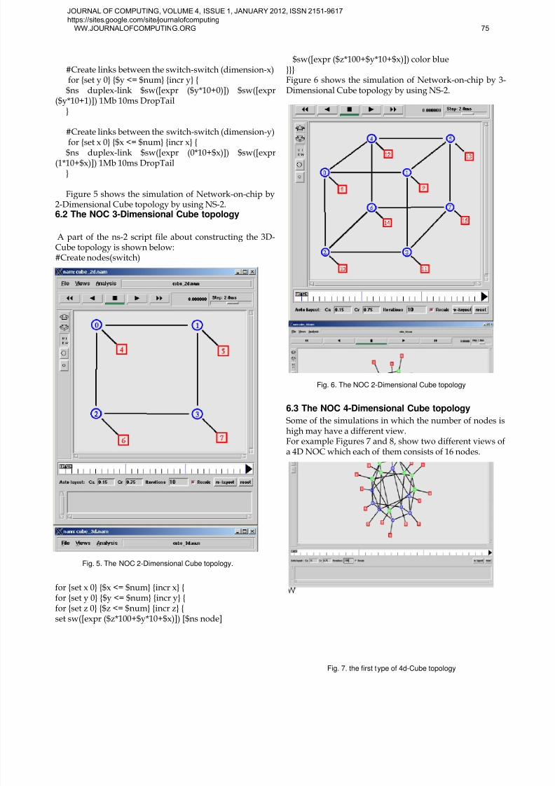
Figure 5 shows the simulation of Network-on-chip by2-Dimensional Cube topology by using NS-2.6.2 The NOC 3-Dimensional Cube topology
A part of the ns-2 script file about constructing the 3D-Cube topology is shown below:#Create nodes(switch)
for {set x 0} {$x <= $num} {incr x} {for {set y 0} {$y <= $num} {incr y} {for {set z 0} {$z <= $num} {incr z} {set sw([expr ($z*100+$y*10+$x)]) [$ns node]
$sw([expr ($z*100+$y*10+$x)]) color blue}}}Figure 6 shows the simulation of Network-on-chip by 3-Dimensional Cube topology by using NS-2.
6.3 The NOC 4-Dimensional Cube topologySome of the simulations in which the number of nodes ishigh may have a different view.For example Figures 7 and 8, show two different views ofa 4D NOC which each of them consists of 16 nodes.
Fig. 6. The NOC 2-Dimensional Cube topology
Fig. 5. The NOC 2-Dimensional Cube topology.
Fig. 7. the first type of 4d-Cube topology
JOURNAL OF COMPUTING, VOLUME 4, ISSUE 1, JANUARY 2012, ISSN 2151-9617
https://sites.google.com/site/journalofcomputing
WW.JOURNALOFCOMPUTING.ORG 75
8/3/2019 Simulation Symmetric N-dimensional Cube Network-on-Chip Architecture by Using Ns-2
http://slidepdf.com/reader/full/simulation-symmetric-n-dimensional-cube-network-on-chip-architecture-by-using 6/7
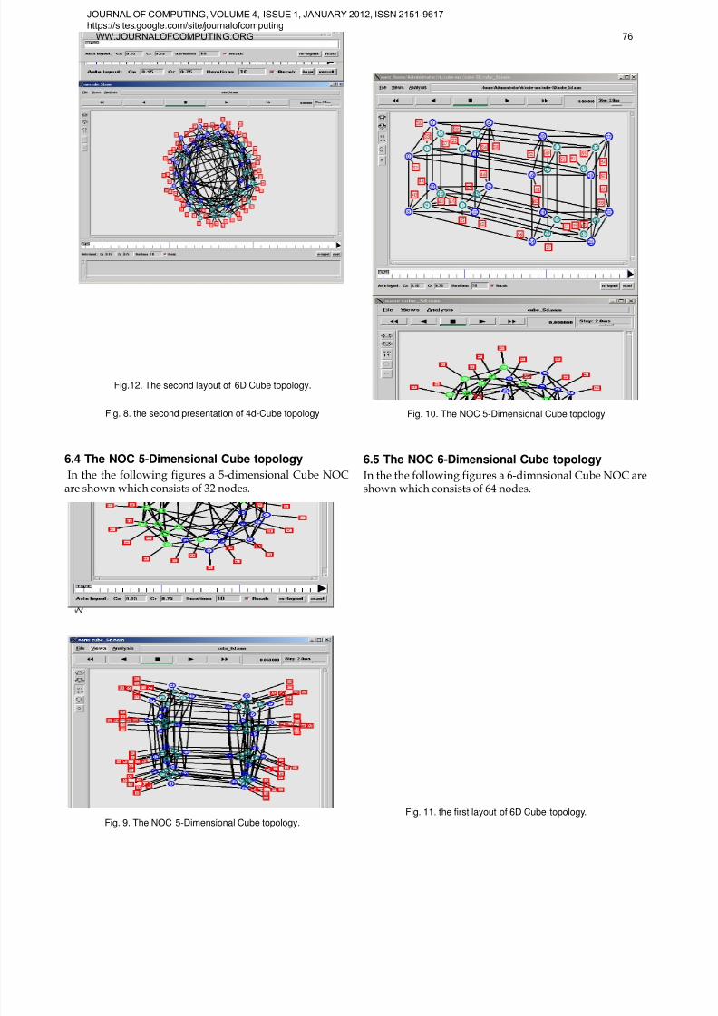
6.4 The NOC 5-Dimensional Cube topology
In the the following figures a 5-dimensional Cube NOCare shown which consists of 32 nodes.
6.5 The NOC 6-Dimensional Cube topology
In the the following figures a 6-dimnsional Cube NOC areshown which consists of 64 nodes.
Fig. 8. the second presentation of 4d-Cube topology Fig. 10. The NOC 5-Dimensional Cube topology
Fig. 9. The NOC 5-Dimensional Cube topology.Fig. 11. the first layout of 6D Cube topology.
Fig.12. The second layout of 6D Cube topology.
JOURNAL OF COMPUTING, VOLUME 4, ISSUE 1, JANUARY 2012, ISSN 2151-9617
https://sites.google.com/site/journalofcomputing
WW.JOURNALOFCOMPUTING.ORG 76
8/3/2019 Simulation Symmetric N-dimensional Cube Network-on-Chip Architecture by Using Ns-2
http://slidepdf.com/reader/full/simulation-symmetric-n-dimensional-cube-network-on-chip-architecture-by-using 7/7
6 CONCLUSION
This paper presents the flexibility of ns-2 simulator so
that there is no restriction on implementing varioustopologies in high dimensions. And also this papershows arguments to effectively use NS-2 network si-mulator for simulating NoCs by Recursive structures.
Our argument is that NS-2 is feasible candidates forsimulating NoCs at a higher abstraction level since nospecific NoC simulator exists so far. The in-built facili-ties of NS-2 can effectively facilitate in the design ofnew protocols for NoCs. The recursive structure of
New Noc architectures makes them ideal for runningrecursive or divide-and-conquer type algorithms.There isn't any limitation for the simulation methodand only the simulation time will be long.
REFERENCES
[1] M. Sgroi, et al, "Addressing the System-on-a-Chip Interconnect Woes
Through Communication-based Design", 38th Design AutomationConference, June, 2001.[2] Luca Benini, Giovanni De Micheli, "Network on Chips: A new SoC
Paradigm", IEEE computer, Jan., 2002.[3] Shashi Kumar, et. al, "A Network on Chip Architecture and Design
Methodology", IEEE Computer Society Annual Symposium on VLSI,Pittsburgh,Pennsylvania, USA, April 2002.
[4] S. Bourduas, "Modeling, Evaluation, and Implementation of Ring-Based Interconnects for Network-on-Chip", May 14, 2008, pp.28-29.
[5] Rochit Rajsumman, ``System-on-a-chip: Design and Test'', ArtechHouse Publishers, 2000.
[6] M. Ali, M. Welzl, A. Adnan, F. Nadeem, "Using the NS-2 NetworkSimulator for Evaluating Network on Chips (NoC)" , 2006 Interna-tional Conference on Emerging Technologies (2006).
[7] K. Weihrauch, Hagen, J.V. Tucker, Swansea, " Recursive and Com-putable Operations over Topological Structures", Jun 1999, pp.43-44.
[8] D. Bertozzi, “Network architecture: Principles and examples,” inNetworks on Chips: Technology and Tools, ser. The Morgan Kauf-mann Series in Systems on Silicon, G. D. Micheli and L. Benini, Eds.Morgan Kaufmann, Jul. 2006, ch. 5, pp. 147–202.
[9] Shashi Kumar, Axel Jantsch, Juha-Pekka Soininen, Martti Forsell,Mikael Millberg Johny Oberg, Kari Tiensyrja and Ahmed Himani,``A network on chip Architecture and Design Methodology'', Proc.,IEEE computer society annual symposium on VLSI, 2002.
[10] Pierre Guerrier, Allen Greiner, ``A generic architecture for on-chippacket switched interconnections'', Proc., Design, Automation andTest in Europe, pp. 250-256, 2000.
[11] Ahmed Hemani, Axel Jantsch, Shashi Kumar, Adam Postula, JohnyOberg, Mikael Millberg, Dan Lindqvist, ``Networks on a chip: AnArchitecture for billion transistor era'', Proc. IEEE NorChip Confe-rence, November 2000.
[12] W. Bux, F. Closs, K. Kuemmerle, H. Keller, and H. Mueller, “Archi-tecture and design of a reliable token-ring network,” IEEE Journal onSelected Areas in Communications, vol. 1, no. 5, pp. 756–765, Nov.1983.
[13] W. Dally and B. Towles, Principles and Practices of InterconnectionNetworks. San Francisco, CA, USA: Morgan Kaufmann PublishersInc., 2003.
[14] S. Bourduas, "Modeling, Evaluation, and Implementation of Ring-Based Interconnects for Network-on-Chip" ,May 14 ,2008 ,pp.30-31.
[15] F. P. Preparata and J. Vuillemin, “The cube-connected cycles: a versa-tile network for parallel computation,” Communications of the ACM,vol. 24, no. 5, pp. 300–309, 1981.
[16] S. Bhattacharya, Y. H. Choi, and W. T. Tsai, “Unidirectional cubeconnected cycles,” IEE Proceedings — Computers and Digital Tech-niques, vol. 140, pp. 191–195, Jul. 1993.
[17] W. J. Dally, “Express cubes: improving the performance of k-ary n-cube interconnection networks,” IEEE Transactions on Computers,vol. 40, no. 9, pp. 1016–1023, Sep. 1991.
[18] W. Dally and B. Towles, Principles and Practices of InterconnectionNetworks. San Francisco, CA, USA: Morgan Kaufmann PublishersInc., 2003.
[19] K. Banerjee et al., “3-D ICs: A Novel Chip Design for Deep-Submicrometer Interconnect Performance and Systems-on-Chip In-tegration”, Proc. of the IEEE, vol. 89(5), pp. 602, 2001.
[20] B. Goplen and S. Sapatnekar, “Thermal Via Placement in 3D ICs”,Proc. Intl. Symposium on Physical Design, pp. 167, 2005.
[21] I. Loi, F. Angiolini, L. Benini, Supporting vertical links for 3D net-works on chip: toward an automated design and analysis flow, Proc.Nanonets, 2007.
[22] J. Cong et al. , “A thermal-driven floorplanning algorithm for 3DICs”, ICCAD, Nov. 2004.
[23] W.-L. Hung et al. , “Interconnect and thermal-aware floorplanningfor 3D microprocessors”, Proc. ISQED, March 2006.
[24] S. K. Lim, “Physical Design for 3D System on Package”, IEEE Design& Test of Computers, vol. 22(6), pp. 532539, 2005.
[25] P. Zhou et al.,”3D-STAF: Scalable temperature and leakage awarefloorplanning for three-dimensional integrated circuits”, ICCAD,Nov. 2007.
[26] C. Guedj et al., “Evidence for 3D/2D transition in advanced inter-
connects”, Proc. IRPS, 2006.[27] IMEC, http://www2.imec.be/imec com/3d-integration.php[28] W. J. Dally, “Performance Analysis of k-ary n-cube Interconnection
Networks”, IEEE Transactions on Computers, Vol. 39, No. 6, pp. 775-785, 1990.
[29] M. Ali, M. Welzl, A. Adnan, F. Nadeem, "Using the NS-2 NetworkSimulator for Evaluating Network on Chips (NoC)" , 2006 Interna-tional Conference on Emerging Technologies (2006).
JOURNAL OF COMPUTING, VOLUME 4, ISSUE 1, JANUARY 2012, ISSN 2151-9617
https://sites.google.com/site/journalofcomputing
WW.JOURNALOFCOMPUTING.ORG 77


![New Conditional Cube Attack on Keccak Keyed ModesThe cube attack [DS09] was introduced by Dinur and Shamir at EUROCRYPT 2009. In their work, an output bit of a symmetric cryptographic](https://img.pdfslide.net/doc/110x75/5e900d775f66b770c51965c8/new-conditional-cube-attack-on-keccak-keyed-modes-the-cube-attack-ds09-was-introduced.jpg)