Embed Size (px)
Citation preview
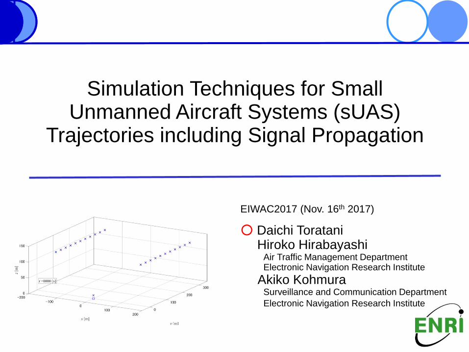
EIWAC2017 (Nov. 16th 2017)
○ Daichi TorataniHiroko Hirabayashi
Air Traffic Management DepartmentElectronic Navigation Research Institute
Akiko KohmuraSurveillance and Communication Department
Electronic Navigation Research Institute
Simulation Techniques for SmallUnmanned Aircraft Systems (sUAS)
Trajectories including Signal Propagation

Table of contentsEIWAC 2017
Nov. 16th 2017
Daichi Toratani
01/16
1. Introduction
- Future sUAS operating environment
- Simulation techniques for sUAS safe operation
2. Research outline
- Radio communication for sUAS
- ADS-B for sUAS
3. Simulation methods- sUAS trajectory simulation
- Radio signal propagation simulation
4. Simulation results- Simulation conditions
- Estimated ADS-B signals at receiving station
5. Conclusion
1. IntroductionEIWAC 2017
Nov. 16th 2017
Daichi Toratani
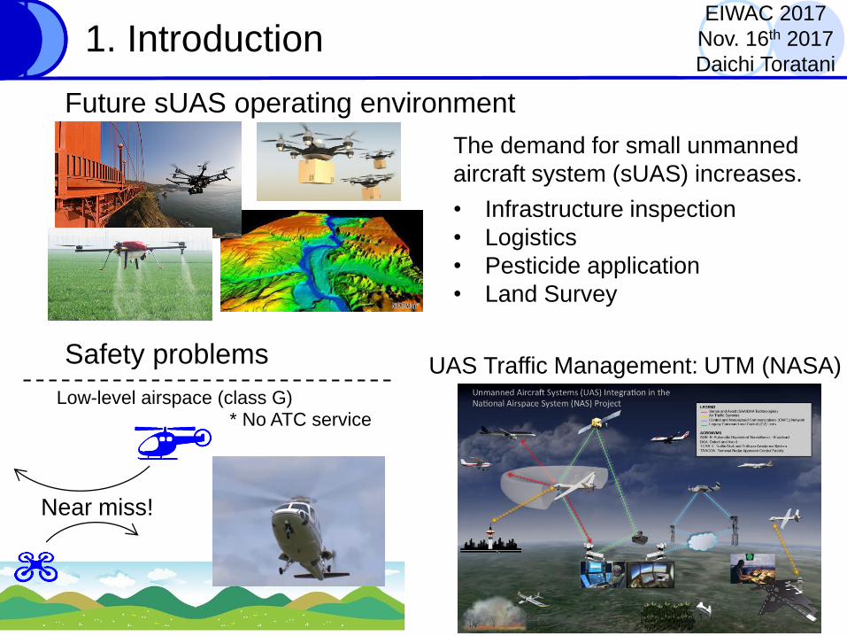
Future sUAS operating environment
The demand for small unmanned
aircraft system (sUAS) increases.
• Infrastructure inspection
• Logistics
• Pesticide application
• Land Survey
UAS Traffic Management: UTM (NASA)Safety problems
Low-level airspace (class G)
Near miss!
* No ATC service
1. IntroductionEIWAC 2017
Nov. 16th 2017
Daichi Toratani
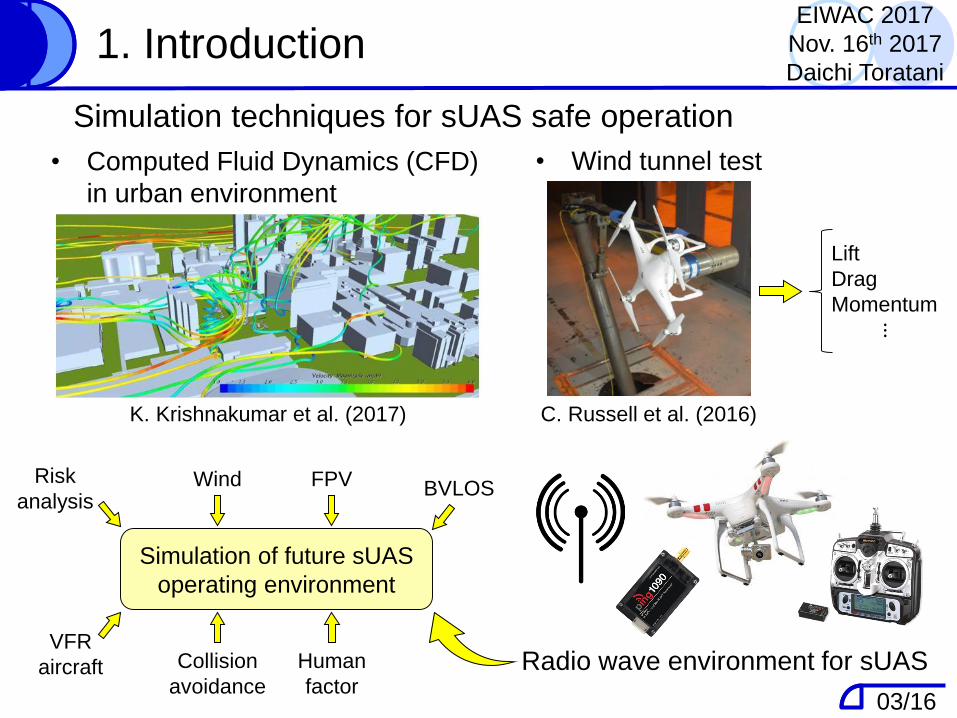
C. Russell et al. (2016)K. Krishnakumar et al. (2017)
• Computed Fluid Dynamics (CFD)
in urban environment
• Wind tunnel test
Simulation techniques for sUAS safe operation
Simulation of future sUAS
operating environment
Lift
Drag
Momentum
⋮
Radio wave environment for sUAS
Wind
Collision
avoidance
VFR
aircraft Human
factor
BVLOSFPVRisk
analysis
03/16
Table of contentsEIWAC 2017
Nov. 16th 2017
Daichi Toratani
1. Introduction
- Future sUAS operating environment
- Simulation techniques for sUAS safe operation
2. Research outline
- Radio communication for sUAS
- ADS-B for sUAS
3. Simulation methods- sUAS trajectory simulation
- Radio signal propagation simulation
4. Simulation results- Simulation conditions
- Estimated ADS-B signals at receiving station
5. Conclusion
04/16
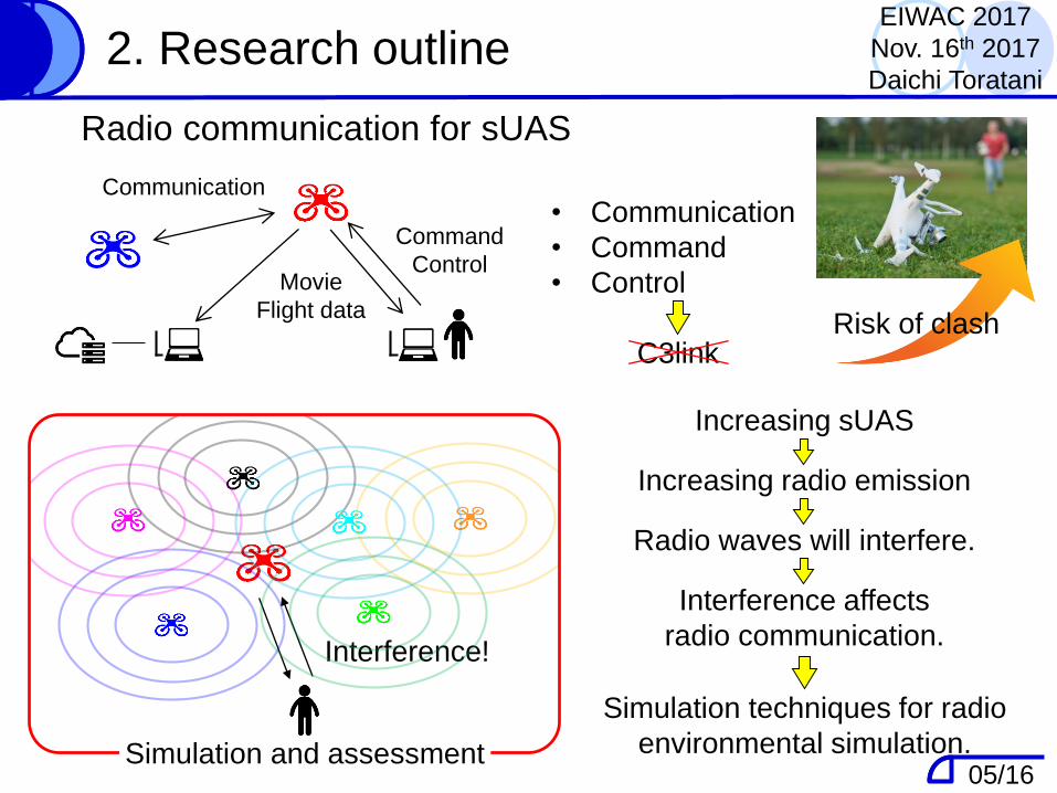
• Communication
• Command
• Control
C3link
2. Research outline
Radio communication for sUAS
Command
ControlMovie
Flight data
Communication
Interference!
Risk of clash
Simulation and assessment
Increasing sUAS
Increasing radio emission
Radio waves will interfere.
Interference affects
radio communication.
Simulation techniques for radio
environmental simulation.
EIWAC 2017
Nov. 16th 2017
Daichi Toratani
05/16
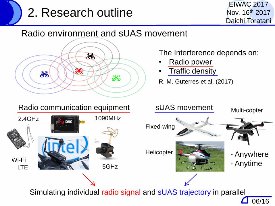
The Interference depends on:
• Radio power
• Traffic density
R. M. Guterres et al. (2017)
Radio environment and sUAS movement
2. Research outline
2.4GHz 1090MHz
Radio communication equipment
LTE 5GHzWi-Fi
sUAS movement Multi-copter
Fixed-wing
Helicopter - Anywhere
- Anytime
Simulating individual radio signal and sUAS trajectory in parallel
EIWAC 2017
Nov. 16th 2017
Daichi Toratani
06/16
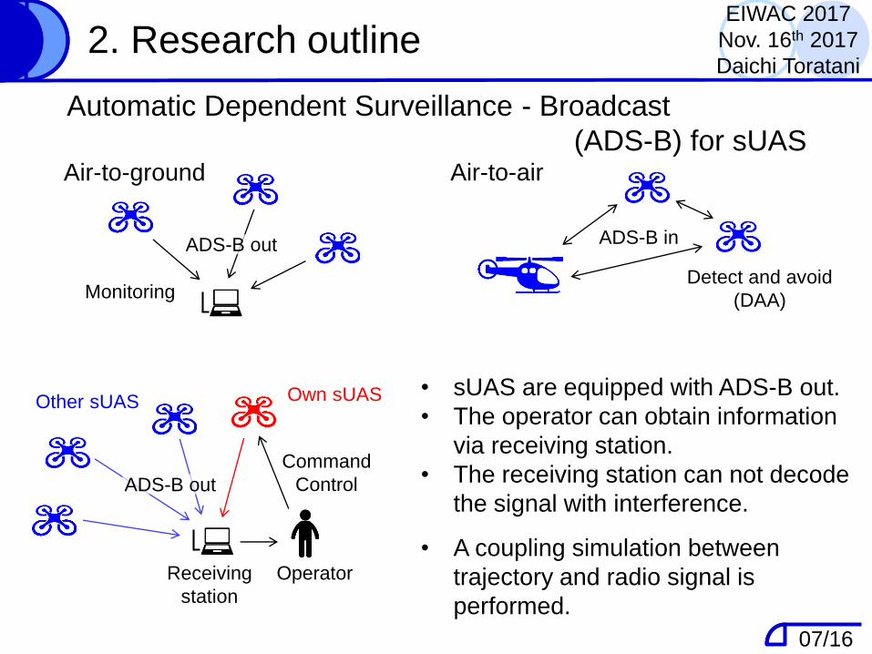
Automatic Dependent Surveillance - Broadcast
(ADS-B) for sUASAir-to-ground Air-to-air
MonitoringDetect and avoid
(DAA)
2. Research outline
Receiving
station
Own sUAS
Operator
Command
Control
Other sUAS
ADS-B out
ADS-B out ADS-B in
• sUAS are equipped with ADS-B out.
• The operator can obtain information
via receiving station.
• The receiving station can not decode
the signal with interference.
• A coupling simulation between
trajectory and radio signal is
performed.
EIWAC 2017
Nov. 16th 2017
Daichi Toratani
07/16
Table of contentsEIWAC 2017
Nov. 16th 2017
Daichi Toratani
1. Introduction
- Future sUAS operating environment
- Simulation techniques for sUAS safe operation
2. Research outline
- Radio communication for sUAS
- ADS-B for sUAS
3. Simulation methods- sUAS trajectory simulation
- Radio signal propagation simulation
4. Simulation results- Simulation conditions
- Estimated ADS-B signals at receiving station
5. Conclusion
08/16
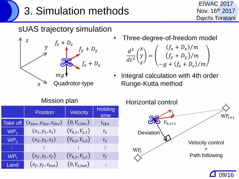
3. Simulation methods
• Three-degree-of-freedom model
𝑑2
𝑑𝑡2
𝑥𝑦𝑧
=
Τ𝑓𝑥 + 𝐷𝑥 𝑚
Τ𝑓𝑦 + 𝐷𝑦 𝑚
−𝑔 + Τ𝑓𝑧 + 𝐷𝑧 𝑚
• Integral calculation with 4th order
Runge-Kutta method
WP𝑖
WP𝑖+1𝑉ℎ,𝑖+1
Deviation
𝑥
𝑦𝑧
𝑓𝑥 + 𝐷𝑥
𝑓𝑦 + 𝐷𝑦𝑓𝑧 + 𝐷𝑧
Mission plan Horizontal control
sUAS trajectory simulation
EIWAC 2017
Nov. 16th 2017
Daichi Toratani
Quadrotor-type
𝑚𝑔
Velocity control
+
Path following
Position VelocityHolding
time
Take off 𝑥𝑡𝑘𝑜, 𝑦𝑡𝑘𝑜 , 𝑧𝑡𝑘𝑜 0, 𝑉𝑧,𝑡𝑘𝑜 𝑡𝑡𝑘𝑜
WP1𝑥1, 𝑦1, 𝑧1 𝑉ℎ,1, 𝑉𝑧,1 𝑡1
WP2𝑥2, 𝑦2, 𝑧2 𝑉ℎ,2, 𝑉𝑧,2 𝑡2
⋮ ⋮ ⋮ ⋮
WPf𝑥𝑓 , 𝑦𝑓 , 𝑧𝑓 𝑉ℎ,𝑓 , 𝑉𝑧,𝑓 𝑡𝑓
Land 𝑥𝑓 , 𝑦𝑓 , 𝑧𝑙𝑛𝑑 0, 𝑉𝑧,𝑙𝑛𝑑 -
09/16
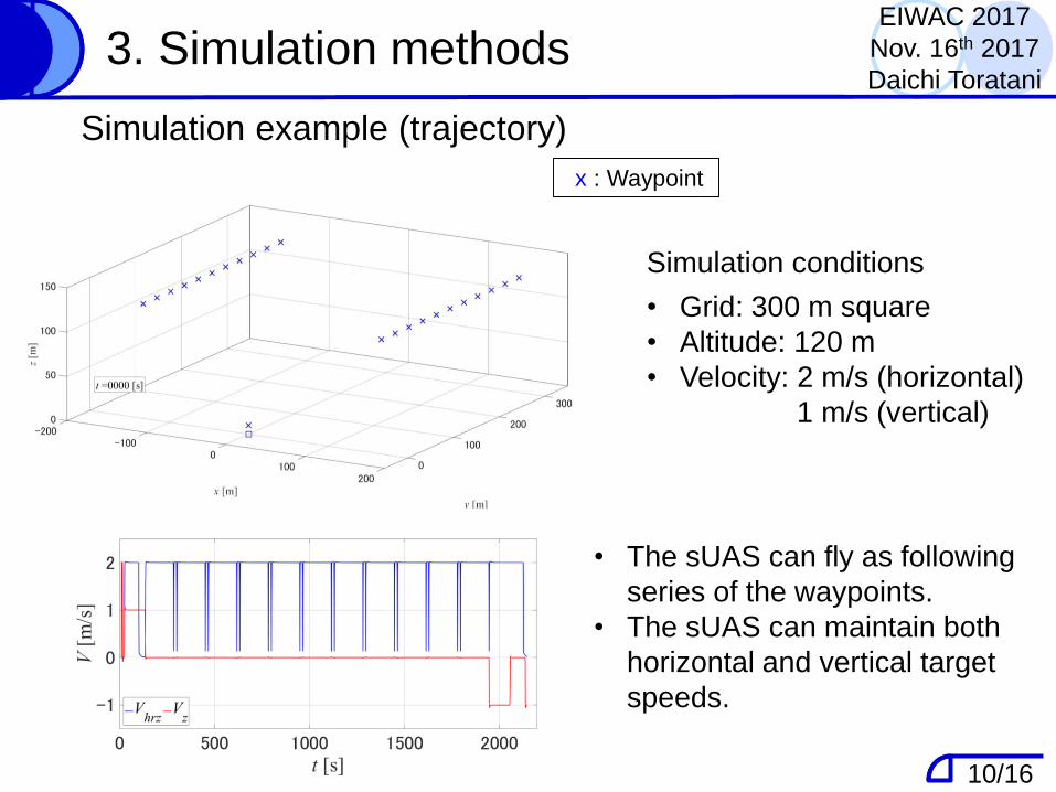
Simulation conditions
• Grid: 300 m square
• Altitude: 120 m
• Velocity: 2 m/s (horizontal)
1 m/s (vertical)
Simulation example (trajectory)
x : Waypoint
• The sUAS can fly as following
series of the waypoints.
• The sUAS can maintain both
horizontal and vertical target
speeds.
3. Simulation methodsEIWAC 2017
Nov. 16th 2017
Daichi Toratani
10/16
3. Simulation methods
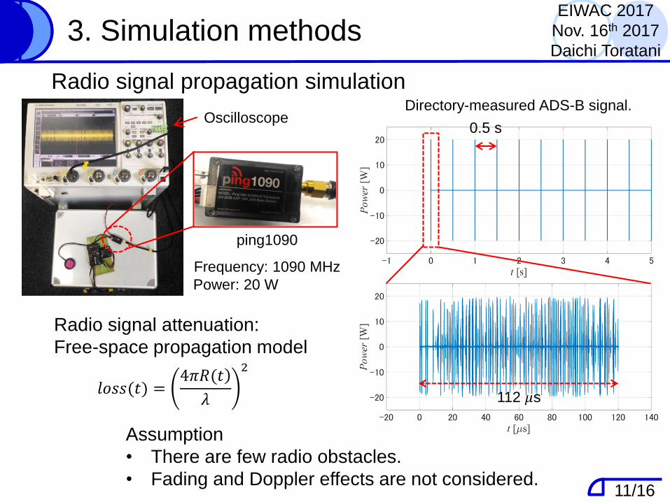
𝑙𝑜𝑠𝑠(𝑡) =)4𝜋𝑅(𝑡
𝜆
2
Radio signal attenuation:
Free-space propagation model
Assumption
• There are few radio obstacles.
• Fading and Doppler effects are not considered.
Radio signal propagation simulation
Oscilloscope
ping1090
0.5 s
Directory-measured ADS-B signal.
EIWAC 2017
Nov. 16th 2017
Daichi Toratani
11/16
112 𝜇s
Frequency: 1090 MHz
Power: 20 W
Table of contentsEIWAC 2017
Nov. 16th 2017
Daichi Toratani
1. Introduction
- Future sUAS operating environment
- Simulation techniques for sUAS safe operation
2. Research outline
- Radio communication for sUAS
- ADS-B for sUAS
3. Simulation methods- sUAS trajectory simulation
- Radio signal propagation simulation
4. Simulation results- Simulation conditions
- Estimated ADS-B signals at receiving station
5. Conclusion
12/16
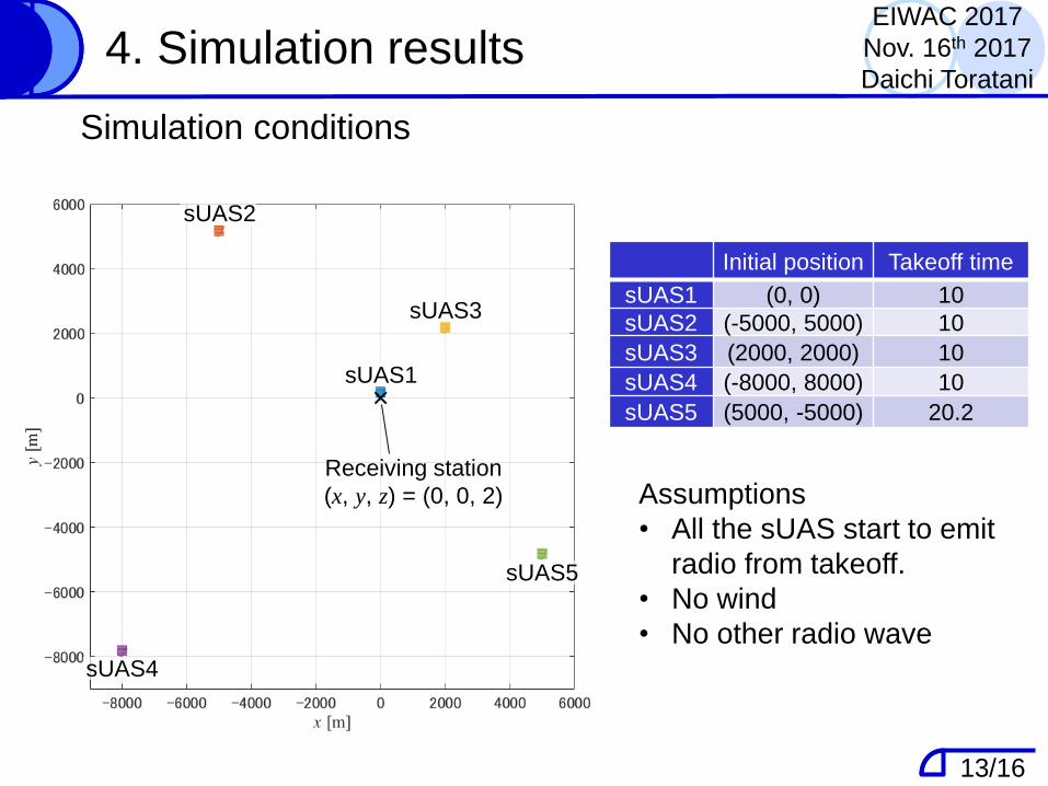
4. Simulation results
Assumptions
• All the sUAS start to emit
radio from takeoff.
• No wind
• No other radio wave
Simulation conditions
EIWAC 2017
Nov. 16th 2017
Daichi Toratani
sUAS1
Initial position Takeoff time
sUAS1 (0, 0) 10
sUAS2 (-5000, 5000) 10
sUAS3 (2000, 2000) 10
sUAS4 (-8000, 8000) 10
sUAS5 (5000, -5000) 20.2
sUAS2
sUAS3
sUAS4
sUAS5
Receiving station
(x, y, z) = (0, 0, 2)
13/16
sUAS1
sUAS2 sUAS3
sUAS4 sUAS5
4. Simulation resultsEIWAC 2017
Nov. 16th 2017
Daichi Toratani
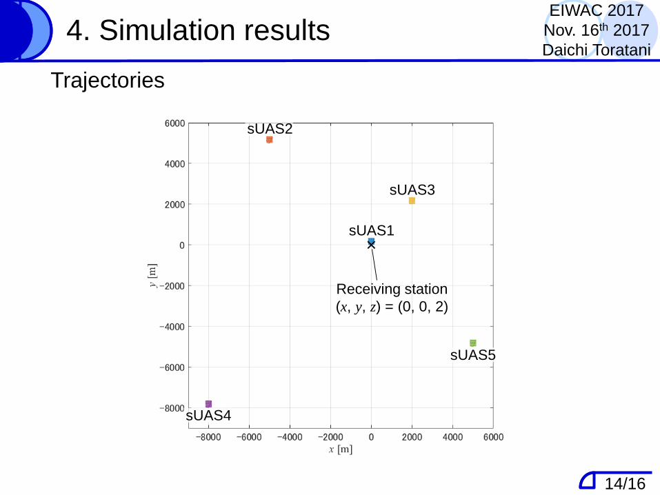
Trajectories
14/16
sUAS1
sUAS2
sUAS3
sUAS4
sUAS5
Receiving station
(x, y, z) = (0, 0, 2)
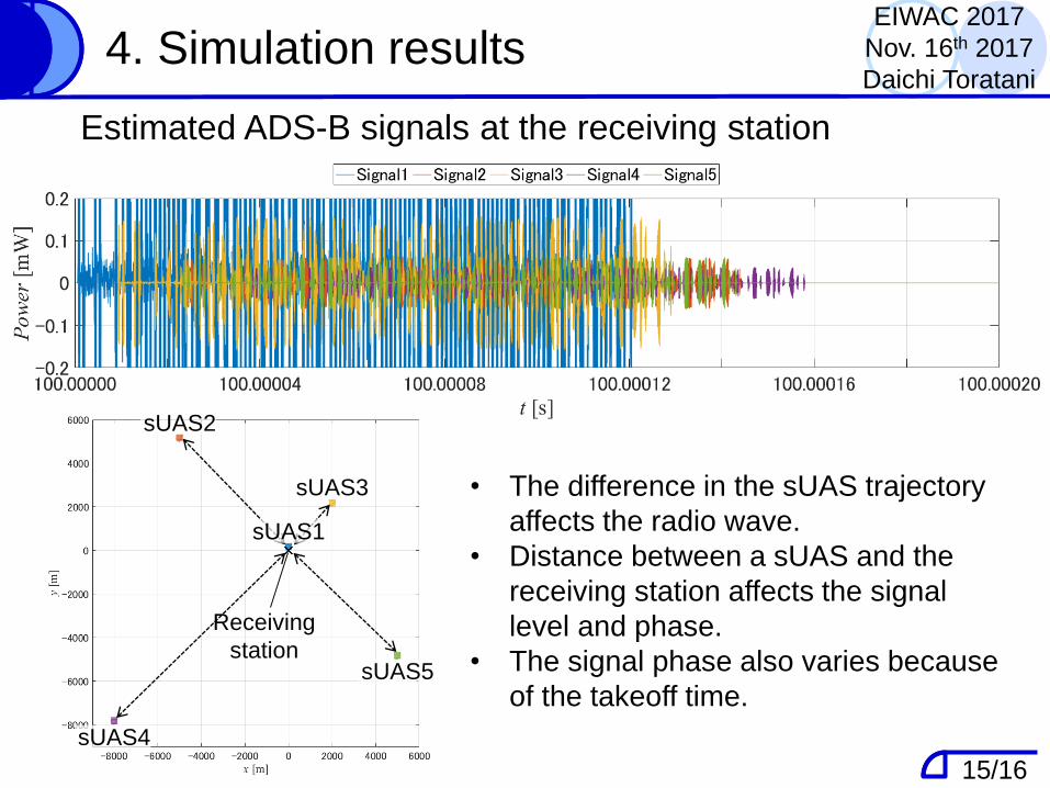
4. Simulation results
• The difference in the sUAS trajectory
affects the radio wave.
• Distance between a sUAS and the
receiving station affects the signal
level and phase.
• The signal phase also varies because
of the takeoff time.
Estimated ADS-B signals at the receiving station
EIWAC 2017
Nov. 16th 2017
Daichi Toratani
15/16
sUAS1
sUAS2
sUAS3
sUAS4
sUAS5
Receiving
station
sUAS1
sUAS2
sUAS3
sUAS4
sUAS5
Receiving
station
5. Conclusion and future works
• This study presented a technique for sUAS trajectory
simulation that includes radio signal propagation of
the ADS-B.
• The ADS-B signal mainly depends on the distance
between the sUAS and receiving station.
• The takeoff time also affected the ADS-B signal.
• Future work will include:
- a hardware-in-the-loop test to investigate signal
decodability of the ADS-B.
- the attitude angle of sUAS to review
the effects of directivity of the antenna.
EIWAC 2017
Nov. 16th 2017
Daichi Toratani
16/16