Embed Size (px)
Citation preview

AC 2009-1314: SIMULATOR FOR TEACHING PROCESS HEATER OPERATINGPRINCIPLES
Charles Baukal, John Zink Institute
Wes Bussman, John Zink Institute
© American Society for Engineering Education, 2009
Page 14.1062.1

Simulator for Teaching Process Heater Operating Principles
Abstract
Process heaters are used in the hydrocarbon and chemical processing industries (HPI/CPI) to
heat hydrocarbon fluids that are being converted into fuels like gasoline or chemicals like
ethylene. Process heater operation involves combustion, heat transfer, and fluid flow principles.
It is not practical to use an actual working heater to teach these principles. This paper describes
an electronic process heater simulator that was developed for instructing engineers and operators
on heater and burner operation.
Introduction
Simulators have been used for many years, for example, in the nuclear and aerospace industries
to simulate both normal operating conditions as well as potentially dangerous situations. The
latter may rarely if ever be seen in actual practice, but it is imperative that operators be prepared
for them in the event they ever do occur. In either case, it is generally not practical or preferable
to let new operators learn initially on the actual equipment because of the potentially dangerous
consequences of making a mistake. Even if an operating error did not result in an unsafe
condition, it could result in lost production, reduced efficiency, or increased pollutant emissions
that could have detrimental economic ramifications for a plant. For these reasons, most new
operators would not be permitted to make adjustments on this type of equipment until they have
had sufficient training. The challenge is to give them realistic training before they work with the
actual equipment.
Figure 1. Schematic of a typical process heater.
Process heaters (see Figure 1) are used in the chemical and refining industries to heat
hydrocarbon fluids flowing through tubes inside the radiant and convection sections. These
Page 14.1062.2
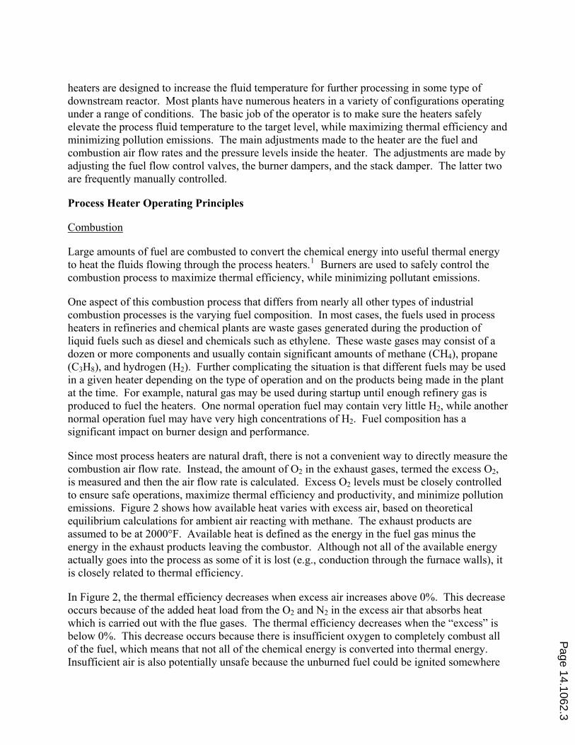
heaters are designed to increase the fluid temperature for further processing in some type of
downstream reactor. Most plants have numerous heaters in a variety of configurations operating
under a range of conditions. The basic job of the operator is to make sure the heaters safely
elevate the process fluid temperature to the target level, while maximizing thermal efficiency and
minimizing pollution emissions. The main adjustments made to the heater are the fuel and
combustion air flow rates and the pressure levels inside the heater. The adjustments are made by
adjusting the fuel flow control valves, the burner dampers, and the stack damper. The latter two
are frequently manually controlled.
Process Heater Operating Principles
Combustion
Large amounts of fuel are combusted to convert the chemical energy into useful thermal energy
to heat the fluids flowing through the process heaters.1 Burners are used to safely control the
combustion process to maximize thermal efficiency, while minimizing pollutant emissions.
One aspect of this combustion process that differs from nearly all other types of industrial
combustion processes is the varying fuel composition. In most cases, the fuels used in process
heaters in refineries and chemical plants are waste gases generated during the production of
liquid fuels such as diesel and chemicals such as ethylene. These waste gases may consist of a
dozen or more components and usually contain significant amounts of methane (CH4), propane
(C3H8), and hydrogen (H2). Further complicating the situation is that different fuels may be used
in a given heater depending on the type of operation and on the products being made in the plant
at the time. For example, natural gas may be used during startup until enough refinery gas is
produced to fuel the heaters. One normal operation fuel may contain very little H2, while another
normal operation fuel may have very high concentrations of H2. Fuel composition has a
significant impact on burner design and performance.
Since most process heaters are natural draft, there is not a convenient way to directly measure the
combustion air flow rate. Instead, the amount of O2 in the exhaust gases, termed the excess O2,
is measured and then the air flow rate is calculated. Excess O2 levels must be closely controlled
to ensure safe operations, maximize thermal efficiency and productivity, and minimize pollution
emissions. Figure 2 shows how available heat varies with excess air, based on theoretical
equilibrium calculations for ambient air reacting with methane. The exhaust products are
assumed to be at 2000°F. Available heat is defined as the energy in the fuel gas minus the
energy in the exhaust products leaving the combustor. Although not all of the available energy
actually goes into the process as some of it is lost (e.g., conduction through the furnace walls), it
is closely related to thermal efficiency.
In Figure 2, the thermal efficiency decreases when excess air increases above 0%. This decrease
occurs because of the added heat load from the O2 and N2 in the excess air that absorbs heat
which is carried out with the flue gases. The thermal efficiency decreases when the “excess” is
below 0%. This decrease occurs because there is insufficient oxygen to completely combust all
of the fuel, which means that not all of the chemical energy is converted into thermal energy.
Insufficient air is also potentially unsafe because the unburned fuel could be ignited somewhere
Page 14.1062.3

else inside the heater. For example, if air is leaking into the convection section, the unburned
fuel could mix with that air, which could lead to burning in the convection section (afterburning)
that could damage the convection tubes. Note that although the maximum available heat is at
0% excess air, heaters are normally operated with some amount of excess air for safety reasons
to ensure there is sufficient O2 to fully combust the fuel, even if there are minor changes in fuel
composition or combustion air properties.
Figure 2. Available heat vs. excess O2 for methane combusted with ambient air (2000°F flue
gas temperature).
Figure 3. NOx and CO vs. excess O2 for methane combusted with ambient air.
The two most common pollutants regulated in process heaters are carbon monoxide (CO) and
nitrogen oxides (NOx).2 These pollutants are sensitive to the amount of excess O2. Figure 3
shows that with increasing excess air levels above 0%, the CO decreases and NOx increases.
Page 14.1062.4

Ideally, the goal is to minimize both pollutants, which can be challenging since each reacts
oppositely to excess air levels. Ultra low NOx burners use a variety of strategies to minimize
both pollutants.3 High levels of CO indicate incomplete combustion and improper burner
operation. High NOx emissions are a problem because of permitted limits for the plant.
Therefore, heater O2 levels are typically controlled as low as possible, without forming high
levels of CO, to maximize thermal efficiency and minimize NOx emissions. For safety reasons,
a manually-operated heater is operated with some excess O2. Variations in ambient air (e.g.,
temperature and humidity), fuel (e.g., temperature and composition), and process operating
conditions (e.g., process fluid flow rate) can cause excess O2 to fall below acceptable levels.4
For this reason, O2 is closely monitored.
Heat Transfer
Heat transfer in a heater is critical to proper operation.5 The bulk of the heat transfer in the
radiant section is by radiation, hence the name radiant section. The bulk of the heat transfer in
the convection section is by convection, hence the name convection section. Conduction losses
through the heater walls reduce the thermal efficiency. The heat flux pattern inside the heater
from the burners is also a critical parameter. Too much heat in a localized area can cause
damage. Flame impingement on process tubes can cause the hydrocarbon fluids being heated to
form coke layers inside the tubes.6 These layers reduce the heat transfer through the tubes which
causes the tubes to overheat and can ultimately lead to a rupture. Ruptured process tubes allow
hydrocarbon fluids to flow into a hot heater and are potentially very dangerous as they can cause
very large fires. Engineers need to know the basic principles of heat transfer in a heater to
maximize performance and avoid unsafe operating conditions.
Fluid Flow
Most process heaters are natural draft, which means no fans or blowers are used to supply the
combustion air to the burners or to remove the combustion products from the heaters. Heater
draft refers to the negative pressure that develops when hot gases rise inside the heater. Draft
pulls in the air needed for combustion and pushes out the products of combustion such as CO2,
H2O, O2 and N2. Ideally, the excess O2 should come from the air being pulled through the
burners, although some also comes from air leaking into the heater through cracks and openings,
which is called tramp air.
Figure 4 shows burners firing across the floor from both sides of a process heater. The figure on
the left shows the heater before the O2 and draft were properly adjusted. Notice how ill-defined
the flames were and how relatively cold the heater was because of incomplete combustion. The
figure on the right shows the flames after the O2 and draft were properly adjusted. The fuel
composition and firing rates were essentially the same in both cases. The flames in the right
photo were well-defined and the heater was hotter which means more throughput of hydrocarbon
fluids. The photos in Figure 4 show how proper adjustments improved flame quality.
An operator can control the heater draft and excess O2 by adjusting the damper on the heater
exhaust stack, referred to as the stack damper, and on each burner, referred to as the burner
damper (sometimes referred to as an air register). Although both the stack and burner dampers
Page 14.1062.5

impact the draft and O2, the stack damper should be primarily used to control the draft while the
burner dampers should be primarily used to control the excess O2.
(a) (b)
Figure 4. (a) Before and (b) after adjusting the O2 and draft in a process heater.
Figure 5. Example screen from heater simulator.
Page 14.1062.6

Heater Simulator
Figure 5 shows an example screen from an electronic heater simulator that was developed
primarily as a teaching tool. The simulator has numerous inputs that can be varied to
demonstrate the effects of a variety of parameters related to fluid flow, heat transfer, thermal
efficiency, pollution emissions, and operating conditions. The simulator is semi-analytical as
most of the calculations are based on well-defined physics. There are also some empirical
equations built into the model to calculate, for example, NOx emissions that have been measured
for a wide range of burner types.
The primary inputs are shown on the left in Figure 5. Many other more detailed inputs can be
modified on a secondary screen. Those inputs are not typically adjusted in the classroom
because they do not directly concern the principles being taught with the simulator and would
take valuable class time to explain. Some of the secondary inputs include design information on
the burner, the radiant and convection sections in the heater, and the process fluid.
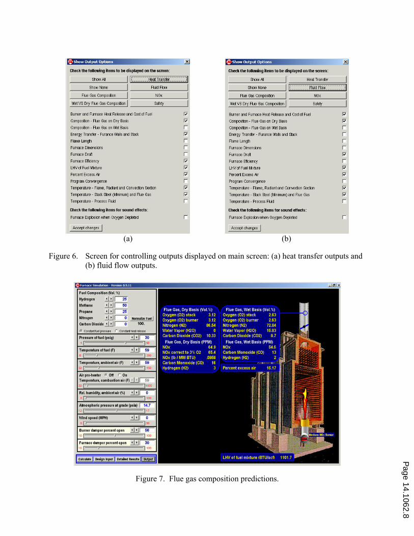
There are also numerous outputs. The example shown is for a simulated refinery fuel consisting
of 50% CH4, 25% C3H8, and 25% H2 at 30 psig supply pressure combusted with ambient air.
The burner and stack dampers were adjusted to 56% and 30% open respectively so the excess O2
and draft at the top of the radiant section were approximately 3% (dry basis) and -0.1" water
column, respectively. These are common operating conditions for these heaters. Students see
how both variables are affected by changes in the positions of those dampers, since those are the
primary adjustments made by the heater operators. If the O2 level gets too low, a warning
appears on the screen stating that the heater is running out of air.
Displaying all outputs as shown in Figure 5 is too busy for instructional purposes, so reduced
sets of outputs are available depending on what principle is being discussed. Figure 6 shows two
examples of screens used to control the outputs. The instructor can individually check boxes to
see specific outputs, or can select categories at the top of the screen to make the selection process
faster and easier. The left and right figures show which outputs are displayed when the “Heat
Transfer” and “Fluid Flow” categories are selected, respectively.
Combustion
There are several parameters of particular interest in heater operation related to combustion. One
is the excess O2 level which is an indicator of thermal efficiency as shown in Figure 2 and
pollution emissions as shown in Figure 3. Other combustion parameters of great importance are
CO and NOx emissions. O2, CO, and NOx are all part of the combustion products in the exhaust
gas. Figure 7 shows the predicted combustion products on both a wet and dry basis, where the
water has been removed in the latter case. These two bases are displayed because flue gas
analyses reported in plants may be on either a wet or dry basis, depending on the type of analyzer
used.
Page 14.1062.7
(a) (b)
Figure 6. Screen for controlling outputs displayed on main screen: (a) heat transfer outputs and
(b) fluid flow outputs.
Figure 7. Flue gas composition predictions.
Page 14.1062.8

Heat Transfer
Figure 8 shows predicted heat transfer parameters for the sample case being considered here.
Some of these parameters include the heat lost through the heater walls, the heat lost out the
stack, the overall heater efficiency, and some selected temperatures. Engineers and operators can
see what happens, for example, to the heater efficiency as important parameters such as excess
O2 are varied. Although it is not the normal instructional purpose of the simulator, it can be used
to vary burner and heater design parameters to study the effects on heat transfer.
Figure 8. Heat transfer predictions.
Fluid Flow
Figure 9 shows the various predicted draft levels inside the sample case heater. The two most
important levels are at the top of the radiant section and at the heater floor level. Process heaters
are typically designed where the former is at approximately -0.1 inches of water column. This is
the least amount of suction inside the heater. The draft is designed to be slightly negative there
so no flue gases leak from the furnace. If flue gases do leak out there, heater damage often
results as well as the potential exposure of hot flue gas to personnel working nearby. The draft
level at the floor is critical for properly sizing the burners to get the necessary combustion air
flow based on the available pressure drop.
Page 14.1062.9

Figure 9. Fluid flow predictions.
Figure 10. Draft variation with elevation in a process heater.
Page 14.1062.10

Figure 10 shows the predicted draft levels inside a heater using the simulator. The green line
shows the design conditions, while the red and blue lines show high and low draft conditions,
respectively. If the draft is too high, then too much tramp air will be pulled into the heater which
can reduce efficiency or cause poor burner operation because the correct amount of air is not
coming through the burners. If the draft is too low, then hot gases can leak out of the heater
causing the problems previously discussed.
Assessment
A detailed assessment of the effect on learning of incorporating the simulator into a continuing
education course was not done for several reasons. The course was undergoing major changes
during the time the simulator was implemented, so it would have been difficult to separate the
effects of the simulator itself. The simulator was also continuously improved over a period of
several years. A pre- and post-test were given to measure what was learned in the course. While
the test scores are available, data were not collected on the specific questions affected by the
simulator, so test scores alone are not appropriate measures of the changes due to using the
simulator.
A post course assessment was given where students used a Likert scale to numerically rate the
benefit of and their interest in each topic covered. They also had the opportunity to provide
written comments. Some selected comments related to the simulator were as follows:
• “. . . simulation was good.”
• “Simulator best part yet . . .”
• “Would really be happy to see Furnace Simulator offered online.”
• “Furnace simulator was the best.”
In addition, anecdotal feedback suggests the simulator has been helpful to the students. Many
have asked if they could get a copy. As a result of these requests, a non-proprietary version of
the simulator will be put on line and will be available at no charge to all alumni and to others
who request and are approved for access. This will allow students to further test their knowledge
and apply the information learned in the course in a safe virtual environment without the fear of
causing unsafe conditions in an actual operating heater.
Conclusions
Using a simulator is not only safer than making adjustments on a production heater, it is also
much faster and easier for instructional purposes. Real heaters take some time to react to
changes in damper positions where the simulator reacts immediately. Also, noise levels are often
high around operating heaters making it difficult to communicate with a group of students, which
is not the case using a simulator in a classroom.
Some important principles that need to be taught related to process heater operation include
combustion, heat transfer, and fluid flow. Excess O2, CO and NOx are important combustion
parameters. Heat losses and overall furnace efficiency are important heat transfer parameters.
Page 14.1062.11

Draft is the primary fluid flow parameter of interest in process heaters. An electronic simulator
has been developed to teach and demonstrate these principles in a continuing engineering
education course.
At the current time the simulator is strictly instructor led, but in the near future this tool will be
put online for use by past and current students at no charge. This will allow the students to test
their knowledge in a safe environment prior to working on actual production units.
Bibliography
1. Baukal, C. (ed.), John Zink Combustion Handbook, FL: CRC Press, 2001.
2. Baukal, C., Industrial Combustion Pollution and Control, New York: Marcel Dekker, 2004.
3. Baukal, C. (ed.), Industrial Burners Handbook, Boca Raton, FL: CRC Press, 2004.
4. Bussman, W. & Baukal, C., An Automatic Advantage. Hydrocarbon Engineering, 13(9), 131-136, 2008.
5. Baukal, C., Heat Transfer in Industrial Combustion, FL: CRC Press, 2000.
6. Vinayagam, K., Minimizing flame impingements in fired heaters. Chemical Engineering, 114(5), 70-73, 2007.
Page 14.1062.12