Embed Size (px)
Citation preview

SIMULINK/MODELSIM CO-SIMULATION OF FPGA-BASED PI
SPEED CONTROL FOR PMSM DRIVE
S T U D E N T : P H A M V A N D U N G
I D : M A 0 2 B 2 0 5
ELECTRICAL ENGINEERING DEPARTMENTSOUTHERN TAIWAN UNIVERSITY OF TECHNOLOGY

CONTENT
Abstract
Introduction
System Description of PMSM Drive and PI Speed Controller Design
Simulink/Modelsim Co-Simulation of PMSM Drive
Conclusion
References

ABSTRACT
The basic principle of (SVPWM) and the design of a PI-control based speed control IC for PMSM from Simulink/Modelsim cosimulation is presented
Firstly, a SVPWM algorithm, vector control method and PI controller are derived and applied in the speed control IC of PMSM drive
Secondly, Verilog that is Hardware Description Language is adopted to describe the behavior of the aforementioned control algorithms.
Finally, Simulations and the results will be discussed.

INTRODUCTION
- PMSM
- FPGA
- Electronic Design Automation (EDA) Simulator Link
- A co-simulation by EDA Simulator Link is applied to PI-control based speed control IC for PMSM drive.
- The Simulink/Modelsim co-simulation architecture is shown in Fig.1
- The PMSM, inverter and speed command are performed in Simulink and the proposed speed control IC described by Verilog code is executed in ModelSim

FIG.1. THE SIMULINK/MODELSIM CO-SIMULATION ARCHITECTURE
SVPWM
DCPower
PMSM
PIIGBT-base
Inverter
PWM1
0* di
qi
di
Park-1modifyClark-1
PWM6
—
—++
—
PWM2PWM3PWM4PWM5PI
1refv
3refv2refvqv
dvvv
*qi
r
*r
+ a,b,c
,d,q
,
Current controller
PIController
Current controller and coodinate transformation
Modelsim
Park Clark
i
ibici,
d,q ,
a,b,c
sin /cos of Flux angle
e Flux angleTransform.
ai
Simulink
A B C
r

SYSTEM DESCRIPTION OF PMSM DRIVE AND PI SPEED CONTROLLER
DESIGN
-The Mathematical Model of PMSM
-Design of Current controller and Coordinate Transformation (CCCT)
-Design of PI controller

THE MATHEMATICAL MODEL OF PMSM
where vd, vq are the d and q axis voltages; id, iq, are the d and q axis currents, rs is the phase winding resistance; Ld, Lq are the d and q axis inductance; is the rotating speed of magnet flux; is the permanent magnet flux linkage.
dd
qd
qed
d
sd
Li
L
Li
L
r
dt
div
1
qqq
eqq
sd
q
de
q
LLi
L
ri
L
L
dt
div
1
f
f e

DESIGN OF CURRENT CONTROLLER AND COORDINATE TRANSFORMATION (CCCT)
Clark
i
iai
bici
,
a,b,c
2 1 1
3 3 31 1
03 3
a
b
c
ii
ii
i
modifyClark-1
1refv
3refv2refv
v
v a,b,c
, vref2
vref3
1
312 2 2
313 2 2
1 0ref
ref
ref
vv
vv
v
,vref1
qi
di
Park
i
i ,
d,q
cos sin
sin cosd e e
q e e
i i
i i
eecos sin
sin cosde e
qe e
vv
vv
Park-1qv
dv
v
vd,q
,

WHICH USES ONE ADDER, ONE MULTIPLIER, AN 1-B LEFT SHIFTER, A SIN/COS LOOK-UP-TABLE AND MANIPULATES 24 STEPS MACHINE TO CARRY OUT THE OVERALL COMPUTATION OF CCCT

DESIGN OF PI CONTROLLER
where Kp is proportional coefficient, Ki is integral coefficient, Yn(n) is the output control volume in the n-sampling time, e(n) is the input deviation in the n-sampling time, e(n-l) is the input deviation in the (n-l )-sampling time.
e(n)K (n) ppU
1)-e(n K1)-(n (n) i ii UU
1)-e(n Ke(n)K1)-(n
(n)(n)Yn(n)
ip
i
ip
U
UU

The designed PI controller circuit adopted by using the FSM method is proposed and shown in this figure which uses one adder, one multiplier, and manipulates 10 steps

SIMULINK/MODELSIM CO-SIMULATION OF PMSM DRIVE

Fig. 10 The Vector Control Block Diagram for PMSM
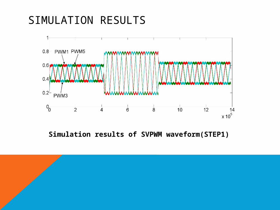
SIMULATION RESULTS
Simulation results of SVPWM waveform(STEP1)

Fig. 12 Simulation results of step speed respond, two-axis current respond and three phase current response

CONCLUSION
This study has been successfully presented a speed control IC for PMSM drive and demonstrated its performance from Simulink/ModelSim co-simulation .Via this design methodology, the Verilog code of the speed control IC can be fast developed, and the risk in experimental development can be greatly reduced.

REFERENCES1.Kung, Y.S., Tsai, M.H.: FPGA-based speed control IC for PMSM drive with
adaptive fuzzy control. In: IEEE Trans. on Power Electronics, vol. 22, no. 6, pp. 2476--2486 (2007)
2.Modeltech, ModelSim Reference Manual (2004)
3.Bogdan Alecsa, Marcian N. Cirstea: Simulink Modeling and Design of an Efficient Hardware-Constrained FPGA-Based PMSM Speed Controller. In: IEEE Trans. Ind. Informatics, vol. 8, no.3, August 2012
4.M. F. Castoldi, G. R. C. Dias, M. L. Aguiar and V. O. Roda. Chopper-Controlled PMDC motor drive using VERILOG code. Proceedings of the 5th Southern Conference on Programmable Logic, (2009), pp. 209~212
5.Weera Kaewjinda and Mongkol Konghirun. Vector Control Drive of Permanent Magnet Synchronous Motor Using Resolver Sensor.In: ECTI Transactions on Electrical Eng., Electronics, and communications Vol.5 ,NO.1 February 2007
6.Li, Y., Huo, J., Li, X., Wen, J., Wang, Y., Shan, B.: An open-loop sin microstepping driver based on FPGA and the Co-simulation of Modelsim and Simulink In: Proceedings of the International Conference on Computer, Mechatronics, Control and Electronic Engineering (CMCE), pp. 223--227 (2010)
7.The Mathworks, Matlab/Simulink Users Guide, Application Program Interface Guide (2004)
8.Implementing a PID Controller in a Microsemi FPGA User guider
9.Y.S. Kung, C.S. Chen, K.I. Wong, M.H. Tsai. Development of a FPGA-based control IC for PMSM drive with adaptive fuzzy control. Proceedings of the Industrial Electronics Society, IECON2005, 31st Annual Conference of IEEE (2005).pp 1544 – 1549
10.Li, Y., Huo, J., Li, X., Wen, J., Wang, Y., Shan, B.: An open-loop sin microstepping driver based on FPGA and the Co-simulation of Modelsim and Simulink In: Proceedings of the International Conference on Computer, Mechatronics, Control and Electronic Engineering (CMCE), pp. 223--227 (2010)