Embed Size (px)
Citation preview
Simultaneous Hand-Eye Calibration and Reconstruction
Xiangyang Zhi and Soren Schwertfeger1
Abstract— Hand-eye calibration is a well-known calibrationproblem. The problem assumes that a camera (eye) is rigidlymounted to the gripper (hand) of a robot arm and aims to findthe transformation between them. In this paper, we proposea novel pipeline for hand-eye calibration without the use of acalibration target.
First we employ feature extraction and matching, followedby an initial hand-eye calibration step using 2-view matches. Inan iterative process, we then alternately employ triangulationand bundle adjustment to optimize the reconstruction and thehand-eye calibration result. Unlike in structure from motionand traditional hand-eye calibration, during this process wealways determine the global camera poses using the hand posesand the estimated hand-eye transformation.
Synthetic-data and real-data experiments are performed toevaluate the proposed approach, and the results indicate thatthe accuracy of our approach is superior to state-of-the-artapproaches. Moreover, the speed of our algorithm is faster thanexisting methods.
I. INTRODUCTION
Calibration is a common problem in computer vision androbotics. Let’s consider a special calibration case: supposethat we have a robot arm with a gripper as its end-effector.In manipulation scenarios, to help locate the position of thetarget, a camera is mounted rigidly on the end-effector. Ifwe use an object recognition algorithm to obtain the poseof the target in the frame of reference of the camera, weneed to know the transform between the camera (eye) andgripper (hand), in order to calculate the pose of the targetwith respect to the gripper. This problem has been studiedabundantly in past years and is well known as hand-eyecalibration.
Unlike camera-camera calibration in stereo vision, onecannot expect to extract feature correspondences betweenthe gripper and the camera. However, this doesn’t mean thathand-eye calibration is impossible. On the contrary, since nofeature correspondence are needed we can apply the solutionsof the hand-eye calibration problem to various other calibra-tion applications, e.g. camera-laser, camera-IMU, laser-IMUand so on.
Hand-eye calibration is based on motion. Suppose that wehave a series of corresponding hand and eye motions, andAij and Bij are the homogeneous transformations of the eyeand hand motions, respectively. Therefore, the equation
AijX = XBij (1)
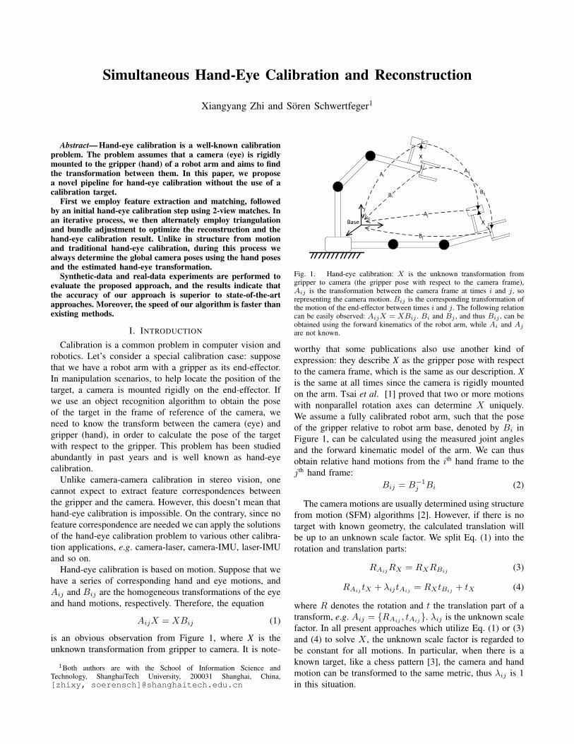
is an obvious observation from Figure 1, where X is theunknown transformation from gripper to camera. It is note-
1Both authors are with the School of Information Science andTechnology, ShanghaiTech University, 200031 Shanghai, China,[zhixy, soerensch]@shanghaitech.edu.cn
Base
Fig. 1. Hand-eye calibration: X is the unknown transformation fromgripper to camera (the gripper pose with respect to the camera frame),Aij is the transformation between the camera frame at times i and j, sorepresenting the camera motion. Bij is the corresponding transformation ofthe motion of the end-effector between times i and j. The following relationcan be easily observed: AijX = XBij . Bi and Bj , and thus Bij , can beobtained using the forward kinematics of the robot arm, while Ai and Ajare not known.
worthy that some publications also use another kind ofexpression: they describe X as the gripper pose with respectto the camera frame, which is the same as our description. Xis the same at all times since the camera is rigidly mountedon the arm. Tsai et al. [1] proved that two or more motionswith nonparallel rotation axes can determine X uniquely.We assume a fully calibrated robot arm, such that the poseof the gripper relative to robot arm base, denoted by Bi inFigure 1, can be calculated using the measured joint anglesand the forward kinematic model of the arm. We can thusobtain relative hand motions from the i
th hand frame to thej
th hand frame:Bij = B
�1j Bi (2)
The camera motions are usually determined using structurefrom motion (SFM) algorithms [2]. However, if there is notarget with known geometry, the calculated translation willbe up to an unknown scale factor. We split Eq. (1) into therotation and translation parts:
RAijRX = RXRBij (3)
RAij tX + �ijtAij = RXtBij + tX (4)
where R denotes the rotation and t the translation part of atransform, e.g. Aij = {RAij , tAij}. �ij is the unknown scalefactor. In all present approaches which utilize Eq. (1) or (3)and (4) to solve X , the unknown scale factor is regarded tobe constant for all motions. In particular, when there is aknown target, like a chess pattern [3], the camera and handmotion can be transformed to the same metric, thus �ij is 1in this situation.
This paper presents a novel pipeline for hand-eye calibra-tion. In the first step we extract features from all images andmatch them. Secondly, according to feature matches betweentwo views, we estimate the relative poses of 2-view matches.Thirdly, with hand poses and relative camera poses of 2-viewmatches, we form several equations of (3) and (4) and solvethe hand-eye transformation. However, this initial calibrationis extremely inaccurate, so we employ triangulation and bun-dle adjustment alternately for several times, in order to refinehand-eye calibration and 3D reconstruction simultaneously.
The contributions of this paper are three-fold. (I) wepropose a novel end-to-end pipeline for hand-eye calibration.Our approach utilizes known tools and techniques, but usesthem in a unique way: We combine 3D reconstruction andhand-eye calibration. Thus our algorithm differs significantlyfrom existing methods which usually use SFM just as aninput source to get the relative camera motions. (II) weextend AX = XB by supposing that any two cameramotions are up to an unequal scale factor, and propose anew method to solve this problem. (III) we demonstrate thehigh accuracy of our approach with synthetic and real dataexperiments.
The remainder of this paper is arranged as follows. SectionII discusses related work. Section III gives an overview of ouralgorithm. Section IV introduces the initial hand-eye calibra-tion algorithm by solving AX = XB and Section V explainsthe bundle adjustment. Section VI presents experiments toanalyze and compare the performance of our algorithm withothers. Section VII gives a conclusion of this work.
II. RELATED WORK
The hand-eye calibration problem was proposed in the1980s and has been studied for nearly 40 years. There isa considerable number of publications about hand-eye cali-bration so far and new ones are still appearing continuously.On the other side, the hand-eye calibration problem itself isdeveloping and has expanded to several branches. In the restof this section, we will review a few hand-eye calibrationalgorithms by branches.
A. Conventional Hand-Eye Calibration
At the very beginning, hand-eye calibration was regardedas to solve Eq. (1), and hand and camera motion are bothwith real metric, i.e. �ij in Eq. (4) is 1. We call this kindof problem conventional hand-eye calibration. Conventionalhand-eye calibration was presented earliest, so there is lotsof literature on that topic.
Early approaches [1], [4]–[6] treated this problem as twoseparate parts: rotation and translation. They firstly estimatedRX using Eq. (3), then utilized the estimated RX to solve tX
using Eq. (4). However, such a separation inevitably leadsto the propagation of the residual error of the estimatedrotation into the translation estimation, so later approachesfor simultaneous estimation of both RX and tX appeared.Daniilidis [7] derived a linear formulation using the dualquaternion representation of Eq. (3) and (4), and then SVDwas utilized to solve RX and tX simultaneously. As a part
of [8], Andreff et al. also proposed a linear formulation ofEq. (1) using the Kronecker product.
Several iterative methods were proposed in past years.Zhuang and Shiu [9] presented an iterative nonlinear methodto minimize the loss function
Pi,j kAijX � XBijk2 to
estimate X . In [10], Horaud and Dornaika separated therotation and translation parts, and used nonlinear optimiza-tion to minimize the sum of the norm of the rotation andtranslation parts. The disadvantage of the nonlinear methodis that an initial solution is necessary, otherwise, it may notconverge to the global optima. In [11], Zhao utilized thelinear formulation proposed in [8] and [7] to construct theso-called second-order cone program (SOCP) problem [12].SOCP is a kind of convex problem where it is guaranteed tofind the global optima even without an initial solution. How-ever, Zhao’s approach doesn’t enforce the orthogonality ofthe rotation matrix, such that an orthogonalization progressis necessary which will increase the error of the rotationestimation.
B. Extended Hand-Eye Calibration
Now, let’s consider that �ij in Eq. (4) is unknown. Inthis case, conventional hand-eye calibration approaches don’twork any more, but since the hand’s poses are in real metricunits, the rigid transformation can still be solved. This prob-lem has no unified name, some authors call it online hand-eye calibration or SFM based hand-eye calibration. We preferthe name extended hand-eye calibration, for this problem is amore general case which includes the conventional hand-eyecalibration. Extended hand-eye calibration approaches can beused to solve the conventional hand-eye calibration problemdirectly. We will classify any approach that can be used tosolve the extended hand-eye calibration as extended hand-eyecalibration approach, even if the authors didn’t announce thatexplicitly. The method proposed in this paper also belongsto extended hand-eye calibration approaches.
The first solution to extended hand-eye calibration wasproposed by Andreff et al. [8]. A linear formulation ofthe hand-eye calibration was derived using the Kroneckerproduct, and Andreff et al. suggested to estimate RX andtX separately. Schmidt et al. [13] exploited two kinds ofnon-linear optimization techniques using Eq. (3) and (4) andtheir dual quaternion representation, respectively. Heller etal. [14] firstly estimated RX using the method proposed byPark et al. [6], and then estimated tX using SOCP.
It is noteworthy that camera motions estimated by SFMare usually noisy, for there often exist wrong feature cor-respondences, especially in environments with repetitivestructures. Such noise will increase the error in the camerapose estimation. As a result, the noisy Aij will mislead theextended hand-eye calibration using AX = XB. In [15] and[16], Heller et al. and Ruland et al. simultaneously proposedvery similar branch-and-bound search methods, which canensure the global optimum with respect to the L1-norm.A slightly extended approach of [15] is given in [17]. Wenotice that the branch-and-bound search approach utilizesfeature correspondences rather than camera motions, thus
overcoming the disadvantage of traditional extended hand-eye calibration, which makes it the state-of-the-art methodto our best knowledge. However, this branch-and-boundsearch method is more than ten times slower than traditionalapproaches.
C. Simultaneous Hand-Eye and Robot-World Calibration
Another branch of hand-eye calibration is simultaneoushand-eye and robot-world calibration. This problem was firstproposed by Zhuang et al. [18]. The additional robot-worldcalibration is to determine the transformation between therobot base frame and world frame which is usually basedon a chess pattern. For that reason, to our best knowledge,all approaches for simultaneous hand-eye and robot-worldcalibration assume that the camera poses are in real metricunits.
Similar to conventional hand-eye calibration, approachesfor simultaneous hand-eye and robot-world calibration canalso be classified by estimating rotation and translationseparately or simultaneously. Early approaches usually es-timated the rotation and translation separately [12], [18]–[20]. As a part of [12], Dornaika and Horaud proposed anonlinear approach which estimates rotation and translationsimultaneously. Li et al. [21] utilized the Kronecker productand dual quaternions to do so. In [22], Malti proposeda bundle adjustment based approach which is similar tothe bundle adjustment partition of our algorithm. However,the difference is that Malti’s approach doesn’t optimize theposition of 3D points while our approach does.
Recently, Wu et al. [23] extended hand-eye calibration toa even more complicated case, called hand-eye, tool-flangeand robot-robot calibration, which could be used in multi-robot cooperation.
One common fact for all three branches of hand-eyecalibration is that they need hand and eye motion correspon-dences, but due to the asynchronicity of different sensors,the correspondences may not hold. As a result, severalprobabilistic approaches [24]–[28] are proposed to solve thiskind of problem. Due to less correlation to this work, wewon’t explain them here.
III. OVERVIEW
For robotic arms the pose of the gripper depends on the an-gles of all arm joints, which are determined by high accuracyencoders. As a result, the gripper pose can be calculated withhigh precision (the repeat localization precision is usuallybetter than 0.2mm). However, the accuracy of SFM highlydepends on the performance of the feature matching. Badfeature correspondences will result in large errors in thecamera pose estimation. Unfortunately, there is no absolutelyperfect feature matching so far. To make things worse, theintrinsic parameters of a camera are also estimated by SFM,and inaccurate intrinsic parameters will reduce the poseestimation accuracy. For all these reasons, the traditionalhand-eye calibration algorithms, which are based on solvingAX = XB, are restricted by the camera pose estimation.In our algorithm, we only utilize AX = XB to guess the
hand-eye transformation initially, but then bundle adjustmentis utilized to obtain a more accurate calibration result. Inother words, we avoid relying on the estimated SFM cameraposes. The experiments in Section VI will illustrate thatthe accuracy of our hand-eye calibration is significantlyimproved.
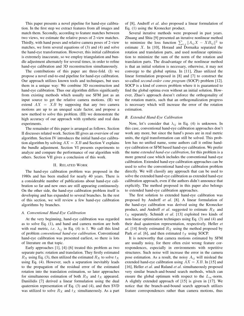
Figure 2 shows a diagram of our algorithm. At thebeginning feature extraction and matching are executed. Thisis a common step in computer vision, so the details areomitted in this paper. After matching features, the relativeposes of two views which have enough correspondencescan be determined. If the readers would like to learn thebasis of 2-view geometry, we refer to [2]. We assume thecameras to be already intrinsically calibrated. With two ormore pairs of hand and camera motions, we can estimatethe rigid transformation between the hand and the camera bysolving AX = XB, which will be explained in Section IV.This serves as the initial calibration value for the next steps.
Suppose that we know the transformation from hand tocamera (X) and one of the hand poses, say Bi, then wecan calculate the corresponding camera pose with respect torobot arm base, say Ai (see Figure 1), using:
Ai = BiX�1 (5)
As we have stated before, the hand poses are usually veryaccurate, so if the hand-eye transformation is estimated pre-cisely, so are the eye poses calculated by Eq. (5). Therefore,instead of estimating camera pose by SFM, we utilize Eq.(5) in triangulation and bundle adjustment.
Triangulation is a fundamental problem in 3D reconstruc-tion. Given a 3D point’s projections onto two or moreimages, triangulation aims to estimate the 3D position ofthe point. Its geometrical principle can be found in [2]. Intriangulation, the camera poses are needed, so that Eq. (5)will be utilized in our algorithm. It should be noted that sincethe camera pose determined by Eq. (5) is in real metric units,the positions of the points will also be in real metric units.
As the most important step of our algorithm we employbundle adjustment [29] to refine the hand-eye calibrationand the reconstruction simultaneously. Details about bundleadjustment will be given in Section V. At the end, ourapproach will output the final hand-eye calibration result,and the reconstruction as the by-product.
Please notice an additional advantage of our approach.If we denote a view by a vertex and two vertices areconnected by an edge if two views are matched (their relativetransform can be calculated based on matched features), weget a view graph. SFM based reconstruction can only bedone on a connected subgraph. As a result, traditional hand-eye calibration can also only work on connected subgraphsindependently, as they require the camera positions to bewithin the same metric. However, this limitation doesn’tappear in our approach, as our method does not estimatethe global camera pose using SFM. Moreover, the severalreconstructions estimated with subgraphs can even be com-bined into one. This ability of our algorithm is very usefulfor robot arms whose motion space is really restricted.
Images Hand poses2-view relative
transform estimation
Feature extraction and matching
Initial hand-eye calibration
TriangulationRefine hand-eye calibration and reconstruction
Hand-eye transformation
Reconstruction
Reach maximum Iterations or terminal condition?
No
Yes
By-product
Fig. 2. Block diagram of the proposed hand-eye calibration algorithm.
The C++ code of our algorithm is available onhttps://github.com/STAR-Center.
IV. INITIAL HAND-EYE CALIBRATION
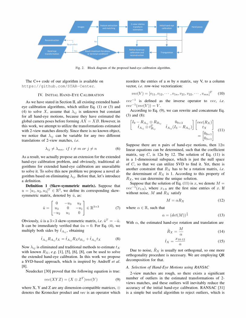
As we have stated in Section II, all existing extended hand-eye calibration algorithms, which utilize Eq. (1) or (3) and(4) to solve X , assume that �ij is unknown but constantfor all hand-eye motions, because they have estimated theglobal camera poses before forming AX = XB. However, inthis work, we attempt to utilize the transformations estimatedwith 2-view matches directly. Since there is no known object,we notice that �ij can be variable for any two differenttranslations of 2-view matches, i.e.
�ij 6= �mn, if i 6= m or j 6= n (6)
As a result, we actually propose an extension for the extendedhand-eye calibration problem, and obviously, traditional al-gorithms for extended hand-eye calibration are unavailableto solve it. To solve this new problem we propose a novel al-gorithm based on eliminating �ij . Before that, let’s introducea definition.
Definition 1 (Skew-symmetric matrix). Suppose thatu = [u1, u2, u3]T 2 R3, we define its corresponding skew-symmetric matrix, denoted by u, as:
u =
2
40 �u3 u2
u3 0 �u1
�u2 u1 0
3
5 2 R3⇥3 (7)
Obviously, u is a 3⇥3 skew-symmetric matrix, i.e. uT = �u.It can be immediately verified that uu = 0. For Eq. (4), wemultiply both sides by tAij , obtaining
tAijRAij tX = tAijRXtBij + tAij tX (8)
Now �ij is eliminated and traditional methods to estimate tX
with known RX , e.g. [1], [5], [6], [8], can be used to solvethe extended hand-eye calibration. In this work we proposea SVD-based approach, which is inspired by Andreff et al.[8].
Neudecker [30] proved that the following equation is true:
vec(XY Z) = (X ⌦ Z
T )vec(Y ) (9)
where X, Y and Z are any dimension-compatible matrices, ⌦denotes the Kronecker product and vec is an operator which
reorders the entries of a m by n matrix, say V, to a columnvector, i.e. row-wise vectorization:
vec(V ) = [v11, v12, · · · , v1n, v21, v22, · · · , vmn]T (10)
vec
�1 is defined as the inverse operator to vec, i.e.vec
�1(vec(V )) = V .According to Eq. (9), we can rewrite and concatenate Eq.
(3) and (8):I9 �RAij ⌦RBij 09⇥3
tAij ⌦ t
TBij
tAij (I3 �RAij )
� vec(RX)
tX
�
=
09⇥1
03⇥1
� (11)
Suppose there are n pairs of hand-eye motions, then 12nlinear equations can be determined, such that the coefficientmatrix, say C, is 12n by 12. The solution of Eq. (11) isin a 1-dimensional subspace, which is just the null spaceof C, so that we can utilize SVD to find it. Yet, there isanother constraint that RX has to be a rotation matrix, i.e.the determinant of RX is 1. According to this property ofRX , we can determine the unique solution.
Suppose that the solution of Eq. (11) is x, we denote M =vec
�1(x1:9), where x1:9 are the first nine entries of x. Ifwithout noise, M and RX satisfy
M = ↵RX (12)
where ↵ 2 R, such that
↵ = (det(M))13 (13)
With ↵, the estimated hand-eye rotation and translation are
RX =M
↵
(14)
tX =x10:12
↵
(15)
Due to noise, RX is usually not orthogonal, so one moreorthogonality procedure is necessary. We are employing QRdecomposition for that.
A. Selection of Hand-Eye Motions using RANSAC
2-view matches are rough, so there exists a significantnumber of outliers in the estimated transformations of 2-views matches, and these outliers will inevitably reduce theaccuracy of the initial hand-eye calibration. RANSAC [31]is a simple but useful algorithm to reject outliers, which is
commonly used in computer vision. In this work, we utilizeit to improve the accuracy of the initial hand-eye calibration.
One RANSAC sample is generated by randomly selectinga certain number of 2-view matches and solving the initalhand-eye calibration from Section IV for them. As two pairsof hand-eye motions could determine the unique hand-eyetransform, in our experiments we used two pairs of 2-viewmatches. Then we calculate the error e for all valid 2-viewsand thus determine the number of inliers for this sample. Werely on a good estimate of the error in order to determine if asample is an inlier or outlier. The first step in the computationof the error e is that we predict Aij using Eq. (3) and (4):
RAij = RXRBijRTX (16)
tAij = RXtBij + (I3 � RAij )tX (17)
The rotation error eR is defined as follows:
eR = kRAij � RAijk2 (18)
Although �ij is not estimated, we assume that �ij is the oneenabling tAij to approach tAij as close as possible, so wedefine the translation error as follows:
et = min�ij
k�ijtAij � tAijk2 (19)
This is a quadratic function about �ij and one can prove thatits minimum is:
et =qktAijk22 � htAij , tAij i2/ktAijk22 (20)
The final error e is a combination of the rotation andtranslation errors. In our experiments, we always set thetranslation unit to meter, so in order to balance the rotationand translation errors, we scale the translation error by 0.1,i.e. the total error is
e = eR + 0.1 ⇤ et (21)
In this work, we let the threshold of the error be 0.01, theminimal inlier ratio be 60%. It should be noted that this isjust an initial guess, it is unworthy to spend much time toget a small accuracy improvement, so we set the maximaliterations of RANSAC to 500.
V. BUNDLE ADJUSTMENT
Bundle adjustment almost always appears in image-based3D reconstruction algorithms, refining camera parametersand positions of 3D points. Specifically speaking, it aimsto minimize the overall reprojection error of each estimatedpoint to the image which can observe that point. In mathe-matical expression: assume that there are m 3D points andn views. xij denotes the projection of the i
th point in the j
th
view, and vij is equal to 1 if the i
th point can be observed bythe j
th view, otherwise 0. Moreover, assume Aj is the rigidhomogeneous transformation from the j
th view frame to theworld frame, Pj(·) is the projection of the j
th view includingdistortion, and let Ti be the predicted homogeneous positionof the i
th point. The bundle adjustment model is formed as:
minPj ,Aj ,Ti
mX
i=1
nX
j=1
vijkxij � Pj(A�1j Ti)k22 (22)
In our algorithm, we utilize Eq. (5) to substitute Aj forbundle adjustment, so we will refine the hand-eye trans-formation and keep the hand poses constant. Besides, weassume that the camera has been calibrated, so that we won’trefine camera intrinsic parameters, although we actuallycould. Our resulting bundle adjustment model is:
minX,Ti
mX
i=1
nX
j=1
vijkxij � Pj(XB
�1j Ti)k22 (23)
The hand-eye transformation consists of 3 rotation parame-ters and 3 translation parameters, while each point consistsof 3 position parameters, i.e. there are 3m + 6 variables in(23). Substantially similar to (22), (23) can also be solvedusing the Levenberg-Marquardt (LM) approach.
The initial guess may be very inaccurate, so as to improvethat, we perform the triangulation and bundle adjustmentalternately for several times. Considering that the hand-eyetranslation is in real metric units, we can set the precisionwe would like to get. In this work, the iteration will termi-nate when estimated hand-eye translation changes less than10�6
m compared to that of last iteration or reaches themaximum number of iterations, which is 10 in this paper.
VI. EXPERIMENTS
We verify our algorithm with various different experi-ments. We implement our algorithm based on Theia [32],an end-to-end C++ SFM library. We utilize SIFT [33] as thefeature descriptor and the Ceres solver [34] as bundle adjust-ment solver. In real-data experiments, we utilize Bouguet’scamera calibration toolbox [35] to obtain the intrinsic andextrinsic parameters of the camera.
We compare our algorithm with three other approaches.To be convenient, in the following experiments, we willdenote our algorithm as “Ours”. Besides, we denote theapproach proposed by Andreff et al. in [8] as “Andreff”.Since “Andreff” needs camera motions, an incremental SFMpipeline implemented by Theia is performed in advance.We denote the approach proposed by Heller et al. in [14],[15] as “Heller11” and “Heller12”, respectively, and featureextraction and matching for both of them comes from Theia,too.
“Ours”, “Andreff” and “Heller12” are all implementedwith C++, and we conduct them on the same 64-bit Linuxplatform with an Intel Core i7-4790 3.60GHz processor.“Heller11” is implemented with MATLAB, without usingmulti threading. Therefore, the readers will notice that, inthe following experiments, the runtime of “Heller11” is muchlonger than the other algorithms.
A. Synthetic-data Experiment
We first evaluate our approach with a synthetic scene anda virtual camera. 500 points are generated randomly insidea cuboid. The center of the cuboid locates at (5, 0, 0), andthe edge lengths along x, y and z axis are 2m, 5m and 5m,respectively. The intrinsic parameters of the virtual cameraare listed in Table I. We will compare the performance of

TABLE IINTRINSIC PARAMETERS OF THE VIRTUAL CAMERA FOR THE SYNTHETIC
EXPERIMENT
Parameters Value Parameters ValueImage width 3000 aspect ratio 1Image height 2000 skew 0
Principle point (1500,1000) distortion NoneFocal length 2200
TABLE IIRUNTIME COMPARISON FOR THE SYNTHETIC-DATA EXPERIMENT.
Approach Andreff Heller11 Heller121 OursRuntime 0.38s 1800s 90s 0.19s
different algorithms regarding two factors: projection noiseand number of hand-eye motions.
Projection Noise 15 camera positions are generated insidea cube whose center is the coordinate origin and edgelength is 3m. With its position, the camera’s orientation isdetermined by assuming that the camera looks towards the3D point cuboid center, i.e. (5, 0, 0). Every point will beprojected to the image plane at every view, but the projectionwill be neglected if it is outside the image. Moreover,every projection will be corrupted by Gaussian noise in thepixel domain with a standard deviation � 2 [0, 3.0] and astep of 0.5 pixel. Finally, we randomly select a hand-eyetransformation, with a random rotation and a translation ofup to 0.2m along each axis, and the hand poses are calculatedusing Bi = AiX .
Number of Hand-Eye Motions In this experiment, wefix the � to be 0.2, and the hand-eye motion varies from 6to 12 with a step of 1, while keeping all other parameterssame to “projection noise” experiment.
To qualify the results, we compute the errors associatedwith rotation and translation as follows:
eR = kRX �RXk2 (24)
et =ktX � tXk2
ktXk2(25)
where RX is the estimated rotation, RX is the truerotation, tX is the estimated translation and tX is the truetranslation. For each noise level, 30 experiments were doneindependently, and the final error is the mean of all 30 errors.
Using a box plot, Figure 3 illustrates the error distri-butions of the hand-eye rotation and translation estimatedby the four algorithms. Clearly, our approach beats theothers both in rotation and translation estimation. Meanwhile,“Heller12” performs worst. The error of rotation estimatedby “Heller11” is smaller than that estimated by “Andreff”.However, “Andreff” performs better regarding translationestimation. We believe that the reason is that the residualerror of the estimated rotation propagates into the translationestimation, because “Heler11” estimates rotation first, while
1To balance the accuracy and runtime of “Heller12”, we set �min to0.0001 in this experiment.
0 0.5 1.0 1.5 2.0 2.5 3.0
σ
0
0.5
1
1.5
2
2.5
3
3.5
4
Err
or
of
Ro
tatio
n
×10-3
0 0.5 1.0 1.5 2.0 2.5 3.0
σ
0
0.02
0.04
0.06
0.08
0.1
0.12
0.14
0.16
Err
or
of
Tra
nsla
tio
n
6 7 8 9 10 11 12
Number of Motions
0
0.5
1
1.5
2
2.5
3
3.5
Err
or
of R
ota
tion
×10-3
6 7 8 9 10 11 12
Number of Motions
0
0.02
0.04
0.06
0.08
0.1
0.12
0.14
Err
or
of T
ransla
tion
Fig. 3. Error of estimated rotation and translation against � (abovetwo figures) or number of motions (below two figures). For each standarddeviation the boxes show the error of the following algorithms: “Ours” (left-most, black), “Heller11” (cyan), “Andreff” (blue) and “Heller12” (rightmost,magenta). To save space, some large outliers which are denoted by ‘+’ inred are not shown.
the translation is calculated afterwards using the estimatedrotation.
Table II gives the average runtime of the approaches ofthe “projection noise” experiment. Since “Andreff” utilizesa linear formulation it is quite fast. It is difficult to com-pare the speed of “Heller11”, since it is implemented inMATLAB. However, as “Heller11” begins with the rotationestimation proposed by Park and Martin [6], which almostconsumes the same time as “Andreff”, we are convinced that“Heller11” should be slower than “Andreff” and “Ours”.All in all, “Ours” runs slightly faster than “Andreff” andthe slowest algorithms are “Heller11” and “Heller12”. Thisresult meets our expectations, since “Ours” is similar toa global SFM pipeline [36], which is regarded to be lessrobust but faster than the incremental SFM pipeline used in“Andreff”, while “Ours” dispenses with global camera poseestimation. “Heller12” is a branch-and-bound search method,which doesn’t need an initial guess, but its computation willgrow exponentially with higher expected precision.

Fig. 4. Example photo from the monocular experiment.
TABLE IIIERROR AND RUNTIME COMPARISON FOR THE MONOCULAR
EXPERIMENT.
Approach Andreff Heller11 Heller122 OursRotation Error 0.00499 0.00544 0.00642 0.000409
Translation Error(m)3 0.0119 0.0310 0.00860 0.000648Runtime4 18.35s nearly 6h 1038s 15.55s
B. Monocular Experiment
It is difficult to obtain the accurate transformation be-tween a camera and another device, so there is no groundtruth available to validate algorithms for extrinsic calibrationrelative to a camera. Indeed, this problem occurs in hand-eye calibration. In this experiment we assume that we arecalibrating “two” cameras using the hand-eye calibrationapproach. But actually the two cameras are the same one:we set up a special scene including a chess pattern, like Fig.4, and afterwards we move the camera and take a seriesof photos, ensuring that the entire chess pattern is in theview in every frame. Afterwards, we calibrate the camerausing a chess pattern calibration approach to determine thecamera poses, and regard this camera as the “hand”. Forthe “eye” poses we assume that we don’t know that thereis a chess pattern and utilize hand-eye calibration approachto determine the transformation between “hand” and “eye”.Obviously, the ground truth is the identity matrix for therotation and a zero vector as translation. In this way, weovercome the problem that no ground truth is available.
In practice, we use the rear camera of a Samsung GalaxyS6 smart phone, with its AutoFocus disabled to satisfy ourassumption that the camera is intrinsically calibrated, and aresolution of 3264 ⇥ 1836 pixels. Each square of the chesspattern is 28⇥28mm. We took 18 images in total at variousdirections and distances.
Table III illustrates the estimation errors and runtime of thefour approaches. Regarding the estimation error, the accuracyof our approach is more than one order of magnitude betterthan the other algorithms, both in rotation and translation.Also, our approach is the fastest of all methods.
2�min = 0.001 in this experiment.3Since the ground truth is zero, the translation error is determined by the
norm of estimated translation rather than Eq. (25).4 The runtime of the monocular experiment is much longer than synthetic-
data experiment, this results from extra feature extraction and matchingwhich are very time-consuming.
(a) (b)
0 1 2 3 4 5 6 7 8 9 100
0.1
0.2
0.3
0.4
Tra
nsl
atio
n n
orm
(m)
no bias
0.3m bias to X
0.3m bias to Y
0.3m bias to Z
(c)
Fig. 5. Gripper-camera experiment. (a) set-up of gripper-camera calibrationexperiment. (b) reconstruction result. (c) the norm of final translation afterbiasing the translation estimated by initial hand-eye calibration.
C. Gripper-Camera Experiment
A Schunk LWA 4P lightweight robot arm with a two-fingergripper is utilized in this experiment, and we let the grippergrip an Asus Xtion Pro Live rigidly, as shown in Figure5(a). Even though the Xtion Pro Live has a depth sensor,only the RGB camera is used here and the resolution is setto 1280⇥ 1024. We use the ROS MoveIt! software packagealong with the Schunk canopen driver to control the arm andget the hand poses with respect to the robot base.
Figure 5(a) also shows two independent scenes deliber-ately made by us, aiming to test the feasibility to mergethe reconstructions for them using our approach. 24 motionsare set manually, half of whom face scene 1 and the othersface scene 2. 24 pairs of gripper poses and the correspond-ing images are obtained during this procedure. No imagesdepicting both scene 1 and scene 2 were taken and thusSFM algorithms cannot create a single model containing bothscenes.
Finally, our approach is performed, and the reconstructionresult is given in Figure 5(b). It should be noted that the re-constructions of scene 1 and scene 2 are merged because thehand-eye calibration is integrated into the bundle adjustment.
Since no true gripper-camera transformation is available,we measure the translation from the gripper to the cam-era by hand with the known mechanical structure of thegripper and Xtion Pro Live, which is approximated to[�0.020, 0.000,�0.107]T . This corresponds to the approx-imate 10cm distance between the camera and the center ofthe other side of the gripper and the fact that the RGB camerawas approximately 2cm off center. The estimated translationby our approach is [�0.0211,�0.00117,�0.119]T , veryclose to the manual measurement.
To evaluate the robustness of the bundle adjustment, wecorrupt the translation result, which is estimated by theinitial hand-eye calibration, by adding 0.3m to the X, Y orZ component, respectively. Figure 5(c) illustrates the norm
(length) of the estimated translation after each iteration. Onecan see that, although the initial guess is corrupted heavily,the calibration results after bundle adjustment still converge,and the norm difference to no bias is less than 10�5
m. Thisexperiment indicates that our algorithm is very robust. Ofcourse, more iterations are needed if the initial guess iscorrupted.
VII. CONCLUSION
In this paper, we present a novel pipeline for hand-eyecalibration. We first propose a hand-eye calibration algorithmbased on 2-view matches as the initial guess. Afterwardsbundle adjustment for simultaneous hand-eye calibration andreconstruction is performed to obtain a more accurate result.It should be noted that our algorithm is an extended hand-eyecalibration solver, i.e. the calibration can be performed solelyfrom a natural scene without any known object. Moreover,our approach is not limited to a set of connected views,and can even merge two or more reconstructions. Mostimportantly, synthetic and real data experiments indicatethat our method is superior to existing algorithms in bothaccuracy and speed of the hand-eye calibration.
REFERENCES
[1] R. Y. Tsai and R. K. Lenz, “A new technique for fully autonomousand efficient 3D robotics hand/eye calibration,” IEEE Transactions onRobotics and Automation, vol. 5, no. 3, pp. 345–358, June 1989.
[2] Y. Ma, S. Soatto, J. Kosecka, and S. Sastry, “An invitation to 3-dvision: from images to geometric models,” 2004.
[3] Z. Zhang, “A flexible new technique for camera calibration,” IEEETransactions on pattern analysis and machine intelligence, vol. 22,no. 11, pp. 1330–1334, 2000.
[4] J. C. Chou and M. Kamel, “Finding the position and orientation of asensor on a robot manipulator using quaternions,” The InternationalJournal of Robotics Research, vol. 10, no. 3, pp. 240–254, 1991.
[5] Y. C. Shiu and S. Ahmad, “Calibration of wrist-mounted roboticsensors by solving homogeneous transform equations of the formAX=XB,” IEEE Transactions on Robotics and Automation, vol. 5,no. 1, pp. 16–29, Feb. 1989.
[6] F. C. Park and B. J. Martin, “Robot sensor calibration: SolvingAX=XB on the Euclidean group,” IEEE Transactions on Robotics andAutomation, vol. 10, no. 5, pp. 717–721, Oct. 1994.
[7] K. Daniilidis, “Hand-eye calibration using dual quaternions,” TheInternational Journal of Robotics Research, vol. 18, no. 3, pp. 286–298, 1999.
[8] N. Andreff, R. Horaud, and B. Espiau, “On-line hand-eye calibration,”in 3-D Digital Imaging and Modeling, 1999. Proceedings. SecondInternational Conference on. IEEE, 1999, pp. 430–436.
[9] H. Zhuang and Y. C. Shiu, “A noise-tolerant algorithm for robotichand-eye calibration with or without sensor orientation measurement,”IEEE transactions on systems, man, and cybernetics, vol. 23, no. 4,pp. 1168–1175, 1993.
[10] R. Horaud and F. Dornaika, “Hand-eye calibration,” The InternationalJournal of Robotics Research, vol. 14, no. 3, pp. 195–210, 1995.
[11] Z. Zhao, “Hand-eye calibration using convex optimization,” in 2011IEEE International Conference on Robotics and Automation (ICRA),May 2011, pp. 2947–2952.
[12] F. Dornaika and R. Horaud, “Simultaneous robot-world and hand-eyecalibration,” IEEE Transactions on Robotics and Automation, vol. 14,no. 4, pp. 617–622, 1998.
[13] J. Schmidt, F. Vogt, and H. Niemann, “Calibration–Free Hand–EyeCalibration: A Structure–from–Motion Approach,” in Pattern Recog-nition. Springer Berlin Heidelberg, Aug. 2005, no. 3663, pp. 67–74.
[14] J. Heller, M. Havlena, A. Sugimoto, and T. Pajdla, “Structure-from-motion based hand-eye calibration using L1 minimization,” in Com-puter Vision and Pattern Recognition (CVPR), 2011 IEEE Conferenceon. IEEE, 2011, pp. 3497–3503.
[15] J. Heller, M. Havlena, and T. Pajdla, “A branch-and-bound algorithmfor globally optimal hand-eye calibration,” in 2012 IEEE Conferenceon Computer Vision and Pattern Recognition (CVPR), June 2012, pp.1608–1615.
[16] T. Ruland, T. Pajdla, and L. Krger, “Globally optimal hand-eyecalibration,” in 2012 IEEE Conference on Computer Vision and PatternRecognition (CVPR), June 2012, pp. 1035–1042.
[17] J. Heller, M. Havlena, and T. Pajdla, “Globally Optimal Hand-EyeCalibration Using Branch-and-Bound,” IEEE Transactions on PatternAnalysis and Machine Intelligence, vol. 38, no. 5, pp. 1027–1033, May2016.
[18] H. Zhuang, Z. S. Roth, and R. Sudhakar, “Simultaneous robot/worldand tool/flange calibration by solving homogeneous transformationequations of the form AX= YB,” IEEE Transactions on Robotics andAutomation, vol. 10, no. 4, pp. 549–554, 1994.
[19] R. L. Hirsh, G. N. DeSouza, and A. C. Kak, “An iterative approachto the hand-eye and base-world calibration problem,” in IEEE Inter-national Conference on Robotics and Automation, 2001. Proceedings2001 ICRA, vol. 3, 2001, pp. 2171–2176 vol.3.
[20] M. Shah, “Solving the robot-world/hand-eye calibration problem usingthe Kronecker product,” Journal of Mechanisms and Robotics, vol. 5,no. 3, p. 031007, 2013.
[21] A. Li, L. Wang, and D. Wu, “Simultaneous robot-world and hand-eyecalibration using dual-quaternions and Kronecker product,” Interna-tional Journal of Physical Sciences, vol. 5, no. 10, pp. 1530–1536,2010.
[22] A. Malti, “Handeye calibration with epipolar constraints: applicationto endoscopy,” Robotics and Autonomous Systems, vol. 61, no. 2, pp.161–169, 2013.
[23] L. Wu, J. Wang, L. Qi, K. Wu, H. Ren, and M. Q.-H. Meng,“Simultaneous Hand-Eye, Tool-Flange, and Robot-Robot Calibrationfor Comanipulation by Solving the AXB=YCZ Problem,” IEEE Trans-actions on Robotics, vol. 32, no. 2, pp. 413–428, 2016.
[24] M. K. Ackerman and G. S. Chirikjian, “A probabilistic solution tothe AX=XB problem: Sensor calibration without correspondence,” inGeometric Science of Information. Springer, 2013, pp. 693–701.
[25] M. K. Ackerman, A. Cheng, and G. Chirikjian, “An information-theoretic approach to the correspondence-free AX=XB sensor cali-bration problem,” in 2014 IEEE International Conference on Roboticsand Automation (ICRA), May 2014, pp. 4893–4899.
[26] Q. Ma, H. Li, and G. S. Chirikjian, “New probabilistic approaches tothe AX = XB hand-eye calibration without correspondence,” in 2016IEEE International Conference on Robotics and Automation (ICRA),May 2016, pp. 4365–4371.
[27] H. Li, Q. Ma, T. Wang, and G. S. Chirikjian, “Simultaneous Hand-Eye and Robot-World Calibration by Solving the Problem WithoutCorrespondence,” IEEE Robotics and Automation Letters, vol. 1, no. 1,pp. 145–152, Jan. 2016.
[28] Q. Ma, Z. Goh, and G. S. Chirikjian, “Probabilistic approachesto the AXB=YCZ calibration problem in multi-robot systems,” inProceedings of Robotics: Science and Systems, AnnArbor, Michigan,June 2016.
[29] B. Triggs, P. F. McLauchlan, R. I. Hartley, and A. W. Fitzgibbon,Bundle Adjustment — A Modern Synthesis. Berlin, Heidelberg:Springer Berlin Heidelberg, 2000, pp. 298–372.
[30] H. Neudecker, “Some theorems on matrix differentiation with specialreference to kronecker matrix products,” Journal of the AmericanStatistical Association, vol. 64, no. 327, pp. 953–963, 1969.
[31] M. A. Fischler and R. C. Bolles, “Random Sample Consensus: AParadigm for Model Fitting with Applications to Image Analysis andAutomated Cartography,” Commun. ACM, vol. 24, no. 6, pp. 381–395,June 1981.
[32] C. Sweeney, “Theia multiview geometry library: Tutorial & reference,”http://theia-sfm.org.
[33] D. G. Lowe, “Distinctive image features from scale-invariant key-points,” International journal of computer vision, vol. 60, no. 2, pp.91–110, 2004.
[34] S. Agarwal, K. Mierle, and Others, “Ceres solver,” http://ceres-solver.org.
[35] J.-Y. Bouguet, “Camera Calibration Toolbox for Matlab,” http://www.vision.caltech.edu/bouguetj/calib doc/index.html, 2004.
[36] P. Moulon, P. Monasse, and R. Marlet, “Global fusion of relativemotions for robust, accurate and scalable structure from motion,”in Proceedings of the IEEE International Conference on ComputerVision, 2013, pp. 3248–3255.

Preprint for the 2017 EEE/RSJ International Conference on Intelligent Robots and Systems (IROS)
Zhi, Xiangyang and Schwertfeger, Sören, "Simultaneous hand-eye calibration and reconstruction",
2017 EEE/RSJ International Conference on Intelligent Robots and Systems (IROS): IEEE, 2017.
Publication Date: September 2017
Provided by Sören Schwertfeger http://robotics.shanghaitech.edu.cn/people/soeren
Mobile Autonomous Robotics Systems Lab http://robotics.shanghaitech.edu.cn
School of Information Science and Technology http://sist.shanghaitech.edu.cn
ShanghaiTech University http://www.shanghaitech.edu.cn/eng
File location http://robotics.shanghaitech.edu.cn/publications