Embed Size (px)
Citation preview

Innovative Methodology
Simultaneous recording of fluorescence and electrical signals by photometricpatch electrode in deep brain regions in vivo
Yasuharu Hirai,1,2* Eri Nishino,1* and Harunori Ohmori11Department of Neurobiology and Physiology, Faculty of Medicine, Kyoto University, Kyoto, Kyoto, Japan; and 2Center forthe Promotion of Interdisciplinary Education and Research, Kyoto University, Kyoto, Kyoto, Japan
Submitted 5 January 2015; accepted in final form 10 March 2015
Hirai Y, Nishino E, Ohmori H. Simultaneous recording of fluo-rescence and electrical signals by photometric patch electrode in deepbrain regions in vivo. J Neurophysiol 113: 3930–3942, 2015. Firstpublished March 11, 2015; doi:10.1152/jn.00005.2015.—Despite itswidespread use, high-resolution imaging with multiphoton micros-copy to record neuronal signals in vivo is limited to the surface ofbrain tissue because of limited light penetration. Moreover, mostimaging studies do not simultaneously record electrical neural activ-ity, which is, however, crucial to understanding brain function. Ac-cordingly, we developed a photometric patch electrode (PME) toovercome the depth limitation of optical measurements and alsoenable the simultaneous recording of neural electrical responses indeep brain regions. The PME recoding system uses a patch electrodeto excite a fluorescent dye and to measure the fluorescence signal asa light guide, to record electrical signal, and to apply chemicals to therecorded cells locally. The optical signal was analyzed by either aspectrometer of high light sensitivity or a photomultiplier tube de-pending on the kinetics of the responses. We used the PME in OregonGreen BAPTA-1 AM-loaded avian auditory nuclei in vivo to monitorcalcium signals and electrical responses. We demonstrated distinctresponse patterns in three different nuclei of the ascending auditorypathway. On acoustic stimulation, a robust calcium fluorescenceresponse occurred in auditory cortex (field L) neurons that outlastedthe electrical response. In the auditory midbrain (inferior colliculus),both responses were transient. In the brain-stem cochlear nucleusmagnocellularis, calcium response seemed to be effectively sup-pressed by the activity of metabotropic glutamate receptors. In con-clusion, the PME provides a powerful tool to study brain function invivo at a tissue depth inaccessible to conventional imaging devices.
fluorescence calcium signal; local field electrical responses; acousticlocal responses; brain activity in vivo; photometric patch electrode
HIGH-RESOLUTION MULTIPHOTON imaging has enhanced our un-derstanding of signaling molecule operations within neuraltissues in the brain in vivo and in regions as small as dendriticspines (Chen et al. 2011; Sabatini et al. 2002; Svoboda andYasuda 2006; Yagishita et al. 2014). Spatiotemporal imagingof calcium ions is particularly important because of the versa-tility of calcium ions as intracellular signaling molecules (Ber-ridge et al. 2000; Hagenston and Bading 2011). More specif-ically, the fluorescence signal of calcium ions has been inter-preted to reflect the electrical activity of neurons in the brain(Chen et al. 2013; Grienberger et al. 2012; Ikegaya et al. 2004),and it has been successfully used to demonstrate the functionalorganization of the primary sensory cortex (Issa et al. 2014;Ohki et al. 2005). However, there are critical disadvantages to
using multiphoton microscopy in vivo. First, because of thescattering of light in living tissues, high-resolution imaging isimpossible in deep brain tissues (Helmchen and Denk 2005;Mittmann et al. 2011). Thus the depth is limited to a maximum1 mm from the brain surface, and the majority of neuralactivity in vivo is beyond the range of microscope imaging.Second, simultaneous electrical recording and imaging in vivois technically challenging (Kitamura et al. 2008; Margrie et al.2003); however, electrical activity of neurons and neural cir-cuits in the brain is a crucial step for elucidating brain function(Chadderton et al. 2014; Eccles 1964; Hubel and Wiesel 1959).
The depth limitation of imaging has been challenged byvarious approaches, including enhancing the penetration oflight through brain tissue (Horton et al. 2013; Mittmann et al.2011), using microendoscopy or fibered fluorescence micros-copy (Flusberg et al. 2005; Jung et al. 2004; Vincent et al.2006), and using a microprism to image multiple neuronsacross a large range of cortical layers (Andermann et al. 2013).Nevertheless, high-resolution imaging is extremely difficult atthe deepest layers of the cortex, midbrain, or brain-stem nucleiin vivo. Microendoscopy that assembled multiple optic fibersand multiple metal electrodes was used to record electricalsignals in vivo (Hayashi et al. 2012). However, the endoscopewas not appropriately designed to track the precise time coursefor the electrical and fluorescence signals. Presently, the mostsophisticated approach for the in vivo recording of neuronalelectrical and fluorescence signals is a microprobe based ondual-core fiber optics, which uses an optical fiber core to exciteand collect fluorescence and an electrolyte-filled hollow core torecord electrical activity (Dufour et al. 2013; LeChasseur et al.2011). However, because recording sites are separated by adistance of �10 �m according to the parallel arrangement oftwo measuring cores, the device is not suitable for precisetracking and comparison of electrical and optical response ofneurons.
In contrast to the aforementioned approaches, we used apatch electrode to measure both the electrical and the fluores-cence signals; thus we have named the electrode a photometricpatch electrode (PME). The PME enabled us not only to exciteand collect fluorescence signals from dye-filled neurons, butalso to apply chemicals locally in brain regions of varyingdepth. We measured fluorescent calcium signals and electricalsignals in response to acoustic stimulation in several auditorynuclei across the auditory pathway from the cochlear nucleusmagnocellularis (NM) in the brain stem to the auditory cortex(field L) of the chick in vivo. These nuclei are located at adepth of 3–7 mm from the brain surface. Moreover, wedemonstrated how sound information is transformed into cal-
* Y. Hirai and E. Nishino contributed equally to this study.Address for reprint requests and other correspondence: H. Ohmori, Dept. of
Neurobiology and Physiology, Faculty of Medicine, Kyoto Univ., Kyoto,Kyoto 606-8501, Japan (e-mail: [email protected]).
J Neurophysiol 113: 3930–3942, 2015.First published March 11, 2015; doi:10.1152/jn.00005.2015.
3930 0022-3077/15 Copyright © 2015 the American Physiological Society www.jn.org
by 10.220.32.247 on October 28, 2016
http://jn.physiology.org/D
ownloaded from

cium signals as it ascends to different levels in the brain.Therefore, the PME is a useful and powerful tool to analyzebrain functions in vivo, both electrophysiologically and opti-cally.
MATERIALS AND METHODS
Outline of PME recording system. The PME recording system iscomposed of sections for laser transmission and for fluorescencedetection (Fig. 1A). The laser-transmitting section consists of the laserassembly, a thinner branch of the bifurcated optical fiber bundle, theelectrode holder assembly, and the PME. The fluorescence-detectingsection receives fluorescence signals from the PME through a thickerbranch of the bifurcated optic fiber bundle and has two measurementoptions. One option used a grating spectrometer coupled with acharge-coupled device (CCD) camera to measure full-range fluores-cence spectrum at sampling intervals of 0.3 s or longer [Fig. 1A(i)].Here, the fluorescence signal was processed from single-trial records.The other option used a photomultiplier tube and a lock-in amplifier
to measure fluorescence signals at faster speeds [1 ms or shortersampling intervals; Fig. 1A(ii)]. Here, signals were sampled by triggerand were ensemble-averaged optionally. The choice of detector de-pended on the type of experiment and the nature of the fluorescencesignal, slow or fast kinetics. The PME is made of quartz capillary witha nickel (Ni)-coated exterior (Fig. 1B). We expected Ni coating toincrease the reflection of light within electrode and to protect theelectrode surface from stains. The proximal end of the PME waspolished (Fig. 1C) to enhance transmission of light between the PMEand the optic fiber bundle. Electrical output of the PME was madethrough a Teflon-coated silver wire and was connected directly to theheadstage of a patch-clamp amplifier (Fig. 1B). The PME was filledwith electrolyte based on artificial cerebrospinal fluid (ACSF; com-positions are in a following section) with additional chemicals in someexperiments to be ejected locally by pressure.
Bifurcated optic fiber bundle. A bifurcated fused-end optical fiberbundle (3-mm core diameter, an assembly of 100 fine optic fibers of0.22 numerical aperture; CeramOptec, East Longmeadow, MA) wasused both to transmit laser light to dye-filled neurons and to detectfluorescence through the PME. A thinner branch (10% of fibers)delivered laser light to PME, and a thicker branch (90% of fibers) ledfluorescence signal from the PME to the detectors (Fig. 1A).
Laser. A semiconductor 488-nm laser (50 mW; Excelsior 488;Spectra-Physics, Santa Clara, CA) was used to excite Oregon GreenBAPTA-1 (OGB-1; Molecular Probes, Eugene, OR). The transmis-sion of the laser light was shutter-controlled. The laser power mea-sured at the distal common end of the bifurcated optical fiber bundlewas 16 mW and was reduced to �4 mW at the distal end of the PMEholder. The laser power was reduced by inserting 25–50% neutraldensity (ND) filter and furthermore by a light-chopper (50% dutycycle) in photomultiplier tube measurements (Fig. 1A). In someexperiments, a 532- or 445-nm laser was used to excite Alexa Fluor555 dextran (Fig. 2B) or the enhanced cyan fluorescent protein(eCFP)-enhanced yellow fluorescent protein (eYFP) fluorescenceresonance energy transfer (FRET) compound (Fig. 2D),respectively.
PME. PME was made from a quartz capillary (1.5-mm outerdiameter, 1.0-mm inner diameter, 75-mm length; Medical Agent,Kyoto, Japan). The capillary exterior was Ni-coated using an auto-catalytic chemical reaction (electroless Ni-plating method; MelplateMB; Meltex, Tokyo, Japan) except for the middle 10 mm becausecoating there was evaporated by heat during electrode pulling. Bothends of the quartz capillary were polished by an optical-fiber-polish-ing machine (Fig. 1C; SpecPro Polisher; Krell Technologies, West-ford, MA). After washing and drying, the quartz capillary was pulledby a laser puller (P-2000/G; Sutter Instrument, Novato, CA) to makea patch electrode of approximately 2- to 3-�m tip diameter (approx-imately 1–3 M� when filled with ACSF; concentrations in mM: 125NaCl, 2.5 KCl, 26 NaHCO3, 1.25 NaH2PO4, 2 CaCl2, 1 MgCl2, and17 glucose, pH 7.4). Optical coupling was direct, without any lensesbetween the bifurcated optical fiber bundle and the PME (Fig. 1B).The electrical signal from the PME is led by Ag wire (100-�mdiameter) coated with Teflon (10-�m thickness; A-M Systems, Carls-borg, WA) to insulate the wire from the Ni-coated capillary surface(Fig. 1B). The electrode holder was designed to align the PME andoptic fiber bundle (Fig. 1B). The holder assembly was made airtight tocontrol the pressure within the PME using a gasket and a silicone tubethat wrapped tightly around the electrode holder and the stainlessferrule of the optic fiber bundle. The PME was filled with ACSF, withadditional chemicals [gabazine, 2-amino-5-phosphonopentanoic acid(AP5), or 4-aminopyridine (4-AP)] that were ejected from the tiplocally by pressure (approximately 0.5–3 psi).
Grating spectrometer. The fluorescence spectrum was measured bya grating spectrometer (C5094), image intensifier (C7979-81), andCCD camera (ORCA-R2) in series [all from Hamamatsu Photonics,Hamamatsu, Japan; Fig. 1A(i)]. The signal-to-noise ratio of the spec-trum was improved by parallel processing of multiple spectra and
Fig. 1. Outline of the photometric patch electrode (PME) recording system. A:laser light is transmitted through a bifurcated optic fiber bundle to the PME.The fluorescence signal is collected and analyzed by a spectrometer coupledwith a charge-coupled device (CCD) camera (i) or a photomultiplier tube(PMT) coupled with a lock-in amplifier (ii). A rotating light-chopper generateda reference signal to the lock-in amplifier. PC, a personal computer to controland acquire data; I–V amp, current-voltage converter amplifier; ND Filter,neutral density filter of 25–50% transmission. B: the PME and optic fiberbundle are aligned in the holder. The holder was made airtight using a gasket(g) and a silicon tube that wrapped tightly around the electrode holder and theoptic fiber bundle to control the pressure within the PME. The exterior of PMEwas nickel (Ni)-coated toward the proximal end. The distal end from the sharptaper to the tip was not coated (see Figs. 2A and 8A). A Teflon-coated Ag wirewas inserted into the electrode through the gasket and connected to theheadstage of a patch-clamp amplifier. C: the proximal end of the PME waspolished. Left: polished end of the PME. Right: unpolished end of a quartzcapillary.
Innovative Methodology
3931IN VIVO RECORDING OF OPTICAL AND ELECTRICAL SIGNAL
J Neurophysiol • doi:10.1152/jn.00005.2015 • www.jn.org
by 10.220.32.247 on October 28, 2016
http://jn.physiology.org/D
ownloaded from
ensemble-averaging of these spectra. In detail, the fluorescence lightfrom the bifurcated optic fiber bundle was first focused through a lenson a detector optic fiber bundle probe of the grating spectrometer.Individual optic fibers within the detector probe were then aligned ina vertical plane to project light as parallel beams to the gratingspectrometer. Light beams were dispersed over wavelengths of 419–678 nm (0.5-nm resolution) and formed a two-dimensional image(wavelength in abscissa vs. individual spectra in ordinate), which wasintensified by an image intensifier, on-chip-integrated by CCD cam-era, frame-transferred to personal computer (PC), and ensemble-averaged to improve the signal-to-noise ratio. Overall time for datareadout took 0.3 s minimum, thus limiting the sampling rate of themeasurement. Data sampling was self-triggered, and fluorescencesignals were processed from single-trial records. Trigger pulses wereissued by the PC at programmed times to synchronize externaldevices. Electrical signals such as outputs of the patch-clamp ampli-fier, acoustic stimuli, and trigger pulses were recorded by a datalogger (EZ7510; 16-bit resolution, 20-kHz sampling rate, 40-gigabytemass storage hard disk recorder; NF, Yokohama, Japan). Becausesampling of the optical data by PC and the electrical signal by the datalogger were run on separate clocks, the time base was slightly adjustedby aligning with trigger timing when they were superimposed (Fig. 3,F and G, and Fig. 6E).
The fluorescence signal from OGB-1 was measured as the mean ofwavelength range (approximately 515–550 nm) after subtraction ofthe dark level (Fdark) that was the mean base level at wavelengthsnear but excluding the laser peak (Figs. 2B and 3B). We intentionallytilted the laser-cut long-pass interference filter (BLP01-488 for488-nm laser; Semrock, Lake Forest, IL) in front of the detector by
approximately 10–15° from the normal angle to produce a small laserpeak in the spectrum [Fig. 1A(i)]. This peak was not affected by theapproach of the PME tip to the dye-filled brain region and was usedas an internal standard to evaluate the spectrum profile in eachexperiment. The PME was replaced when spectrum profile changedsignificantly by repeated penetration in the brain. A long-pass inter-ference filter of matched cutoff wavelength was used for the laser ofother wavelength.
Photomultiplier tube and lock-in amplifier. A photomultiplier tube(H6780-02; Hamamatsu Photonics) was used for fluorescence mea-surements when a high-speed sampling was required (Figs. 4–7).Output of the photomultiplier tube was current-voltage converted(LI-76; NF), low-pass filtered, and amplified through a lock-in am-plifier with a short time constant (LI-5640; NF). A reference signal(�2 kHz) was provided by a light-chopper (50% duty cycle; 5584A;NF) to the lock-in amplifier (Fig. 1A). Time constant of the lock-inamplifier was set at 1 ms in most experiments since the time course offluorescence signal was not different between 0.3 and 1 ms. Fluores-cence signal from the lock-in amplifier, current signal from thepatch-clamp amplifier, and left and right ear sound stimuli weresampled simultaneously (approximately 100-Hz to 2-kHz samplingrate, 16-bit resolution; NI-DAQm; National Instruments, Tokyo, Ja-pan). Sampling was trigger-driven, and fluorescence responses toacoustic stimuli were occasionally ensemble-averaged. Here,488-nm laser light was eliminated by a laser-cut long-pass filter(520 nm and long wavelength; Di01-R514; Semrock) and wasfurther filtered out by an interference filter (approximately 525- to557-nm wavelength; FF01-542; Semrock) before sampling by thephotomultiplier tube.
Fig. 2. Recording of fluorescence signals in brain slicesusing a spectrometer. A: the PME assembly (right) and alaser-excited granule cell from the rat hippocampus (left).The inset shows the laser-illuminated neuron at a largermagnification with a calibration bar of 10 �m where thePME tip is indicated by dotted lines. B: 2 fluorescencespectra recorded from a dye-filled nucleus magnocellularis(NM) neuron of the chick by the on-cell and detached PME.Cells were labeled with Alexa Fluor 555 dextran (10-kDamol mass) and were excited by a 532-nm laser. a.u.,Arbitrary units. C: the percentage of the drop in fluores-cence intensity after detachment of the PME was plotted forindividual cells. After detachment of the PME, the fluores-cence intensity dropped to approximately 42–88% (68 �9.5%, n � 115 cells). The difference signal was notaffected by the type of fluorophore; thus data from variousdyes were combined. D: a stacked display of time seriesspectra shows fluorescence resonance energy transfer(FRET) responses from a rat cortical pyramidal neuronafter subtraction of the dark level (Dark in B). The spectrumwas sampled at 20-s intervals, and every other data areplotted. Spectra before (dotted line) and after (thick blacksolid line) the bath application of a high-KCl medium (30mM; arrow) are indicated in D and E. The backgroundspectrum (BG; gray broken line) was overlaid on the 1sttime series record. Arrows Y and C, peaks of enhancedyellow fluorescent protein (eYFP) and enhanced cyan flu-orescent protein (eCFP), respectively. E: the BG was sub-tracted to show the spectrum change induced by KCl.Vertical gray bars indicate the wavelength ranges used tocalculate eCFP and eYFP fluorescence intensity. In A andD, neurons were transfected by an eCFP-eYFP-basedFRET compound and were excited by a 445-nm laser(Takatsuka et al. 2005).
Innovative Methodology
3932 IN VIVO RECORDING OF OPTICAL AND ELECTRICAL SIGNAL
J Neurophysiol • doi:10.1152/jn.00005.2015 • www.jn.org
by 10.220.32.247 on October 28, 2016
http://jn.physiology.org/D
ownloaded from

Evaluation of fluorescence signal. The fluorescence signal (�F)was evaluated as a ratio relative to the base level at the start of eachrecord (F). In spectrometer mode, a dark level was calculated at thewavelength range separated from the measured fluorescence and wassubtracted from the denominator (F�Fdark). However, the dark levelwas not subtracted in photomultiplier tube mode because only thewavelength range of signal fluorescence was measured. �F was thusevaluated as �F/(F�Fdark) for the spectrometer and �F/F for thephotomultiplier tube.
Cross-correlogram to evaluate amplitude pairs of field current andfluorescence signals. Because fluorescence signals were delayed tocurrent responses, corresponding peaks of fluorescence and currentsignals were identified by displacing the fluorescence signal by theamount of delay between the two signals. Delay was calculated fromthe correlogram by using the MATLAB function xcorr. Paired traceswere overlaid, and the corresponding amplitude of the two peaks wasmeasured manually under visual control (Fig. 4C).
Background fluorescence light. The level of background fluores-cence light was high with the PME recording system and on averageoccupied 68% (approximately 42–88%) of the total fluorescent lightdetected from the dye-filled single neurons (Fig. 2C). The backgroundfluorescence was likely attributable to the PME assembly includingelectrode holder, PME, and optic fiber bundle itself as illuminated bystrong laser light (Fig. 1B). However, the background level was stable,provided it was illuminated by a constant laser power. A brighter light
emission from the neuron increases the fluorescence light level cap-tured by the PME. Consistently, the resolution of signal fluorescencewas improved when the fluorescence light level was increased sever-alfold of that on the brain surface in the recording from the dyeinjection site in vivo (Fig. 3, B and C). The fluorescence light capturedby the PME in these in vivo experiments may reflect the number ofneurons in ensemble-synchronized activity or the amount of the dyethat filled local neurons.
Animals. Chicks approximately 2–6 days after hatching (approxi-mately P2-6) were used for in vivo experiments and chicks (approx-imately P2-3) and rat pups (P9) were used for slice experiments asdetailed in the following sections. All experimental procedures werereviewed and approved by the Animal Experimentation Committee ofthe Kyoto University.
Recording from neurons in vivo and acoustic stimulation. Chickswere anesthetized with an intraperitoneal injection of urethane (1mg/g body wt). Additional injection of urethane or chloral hydratewas made to maintain the level of anesthesia. Surgical procedures anddevices used for acoustic stimulation were previously described (Fu-kui et al. 2006; Nishino et al. 2008).
Bolus injection of OGB-1 AM (1 mM in ACSF; Murayama et al.2007; Stosiek et al. 2003) was made by using a glass electrode witha tip diameter of approximately 20–30 �m. A tungsten wire (15 �m,Teflon-coated) was inserted into the electrode to detect the fieldcurrent response to acoustic stimulation. The electrode was inserted
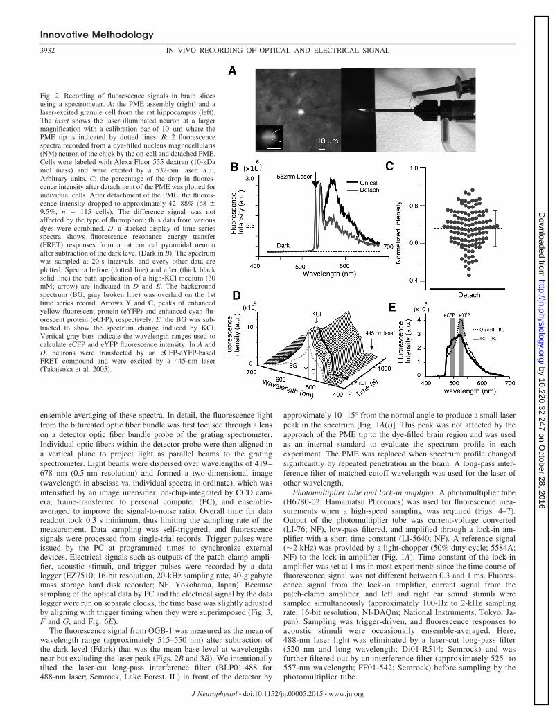
Fig. 3. Oregon Green BAPTA-1 (OGB-1) AM spectral signalsfrom the auditory cortex (field L). A: a frontal section of chickcerebral cortex containing field L. The fluorescence image issuperimposed on a bright-field image. MPall, medial pallium;LPall, lateral palllium; D, dorsal; L, lateral. The vertical brokenline indicates the midline. B: the spectrum increased when thePME approached the field L (black line on the brain surfaceand thick gray line at the field L). The field L was preloadedwith OGB-1 AM. The broken line indicates the base level(Fdark). The arrow indicates the 488-nm laser peak. C: anincrease of fluorescence in B. The electrode approaching wasstopped when the fluorescence intensity became stable. D andE: the spontaneous local field current recorded with artificialcerebrospinal fluid (ACSF)-filled PME (D) with the boxed areaexpanded (E). F: local field current (black) and overlaid fluo-rescence (gray). Binaural acoustic stimulation (80-dB whitenoise; gray line at the bottom) was applied unless otherwisespecified. G: gabazine (GZ; 5 mM) enhanced responses. H:6,7-dinitroquinoxaline-2,3-dione (DNQX; 50 mM) blockedfield responses. I and J: current (black) and fluorescence (gray)signals correspond to asterisks in F (I) and G (J). The localfield current was induced in conjunction with the acousticstimulus and is overlaid (gray with dots) in J and K. K: thecurrent (black) and fluorescence (gray) signals recorded in2-amino-5-phosphonopentanoic acid (AP5; 25 mM) and gaba-zine (5 mM).
Innovative Methodology
3933IN VIVO RECORDING OF OPTICAL AND ELECTRICAL SIGNAL
J Neurophysiol • doi:10.1152/jn.00005.2015 • www.jn.org
by 10.220.32.247 on October 28, 2016
http://jn.physiology.org/D
ownloaded from

vertically to the field L at a depth of �3 mm from the cerebral surface,1.5 mm lateral, and approximately 1.2–1.5 mm rostral of the lambdoidsuture; the inferior colliculus (IC) at a depth of �7 mm from thecerebral surface, approximately 3.7–4.0 mm lateral, and approxi-mately 1.7–2.0 mm rostral of the lambdoid suture; or the NM at adepth of �7 mm, approximately 1.3–1.4 mm lateral at the rostrocau-dal level of the inion through the cerebellum. The NM was ap-proached by tilting the head with the beak downward by 30°. After 1h of OGB-1 AM injection, the PME was inserted vertically (Fig. 3A).The electrode was advanced by a motor-driven micromanipulator(DMA-1050; Narishige, Tokyo, Japan). While the PME was ap-proaching, acoustic search stimulus of white noise burst (80-msduration with 5-ms rise and fall envelope) was applied every 5 s, andfluorescence signal was measured (Fig. 3, B and C). The OGB-1fluorescence response to acoustic stimulus was tested when the fluorescencelevel became stable. Binaural acoustic stimulation of 80-dB whitenoise was generally applied unless otherwise specified. Sound stim-ulation and data acquisition were controlled by customized softwarewritten in MATLAB. All experiments were performed in an electri-cally shielded soundproof chamber placed within a soundproof booth.Local field currents were low-pass filtered at 15 kHz (2-pole) andwere recorded using a patch-clamp amplifier (MultiClamp 700B;Axon Instruments, Union City, CA).
Brain slices. Chicks were injected with OGB-1 AM as describedabove and decapitated after 1 h in deep anesthesia, and brain-stemslices at the level of the NM (thickness 300 �m) were made aspreviously described (Kuba et al. 2003). After the incubation of slicesat 35°C for approximately 30–45 min in high-glucose medium (75NaCl, 2.5 KCl, 26 NaHCO3, 1.25 NaH2PO4, 2 CaCl2, 1 MgCl2, and
100 glucose, pH 7.4), electrical and fluorescence recordings weremade at room temperature (approximately 25–27°C) in ACSF byusing an upright microscope (BX51WI; Olympus, Tokyo, Japan). Insome brain slice experiments, NM neurons were loaded with AlexaFluor 555 dextran (10-kDa mol mass) retrogradely by dye injection tothe contralateral side a day before the experiment (Fig. 2B). Slices ofrat cerebral cortex or hippocampus were similarly made for experi-ments in Fig. 2, A, C, and D. These neurons were labeled with theeCFP-eYFP compound (Takatsuka et al. 2005).
RESULTS
Validation of PME to measure fluorescence signals fromdye-filled neurons in brain slices. A beam of laser light fromthe tip of the PME excited the fluorescence of a neuronexpressing a fluorescent protein (Fig. 2A, inset). The fluores-cence was collected by the PME and processed as a spectrum.The sensitivity of the PME to capture the neuron-emittedfluorescence was evaluated as the difference in the spectrabetween the cell-attached and after detachment of the PMEfrom dye-filled neurons. Figure 2B illustrates two spectrameasured in a neuron of the NM (avian cochlear nucleus),which was filled with Alexa Fluor 555 dextran. A 532-nm laserfrom the tip of the PME excited the dye. The fluorescencespectrum showed a peak between 550- and 650-nm wave-lengths and two additional peaks near approximately 530–550nm. These latter two peaks were due to a leak through the
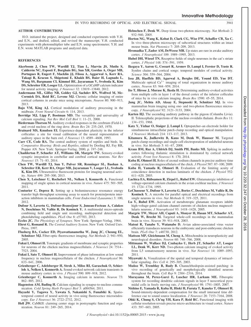
Fig. 4. Correlation between current and fluorescence signals inthe field L. Fluorescence was detected by a photomultipliertube in gabazine (0.5 mM). A: local field currents (black) andfluorescence responses (gray) to acoustic stimuli (gray line atthe bottom). Current and fluorescence responses were gener-ally coupled. Uncoupled responses are indicated by Œ or � (seemain text). B: the ensemble averages of fluorescence (top) andcurrent (bottom) signals. Individual traces are overlaid. C: 2examples of the cross-correlogram between current and fluo-rescence signals. From top to bottom, each subpanel illustratesthe cross-correlogram, fluorescence, current traces, and acous-tic stimulus. In the correlogram, t indicates the delay time, andx.c. represents the correlation coefficient between 2 traces. Theshort black line at the right end of the fluorescence signalindicates the time displaced (delay time) to align the currentand fluorescence signals to measure the peaks of a pair (boxes).D: scatter plots of paired fluorescence (F) and current ampli-tudes. Both acoustic and spontaneous responses are included.Liner fit slope is 0.94%/nA (r � 0.58, lower group) and0.60%/nA (r � 0.76, upper group).
Innovative Methodology
3934 IN VIVO RECORDING OF OPTICAL AND ELECTRICAL SIGNAL
J Neurophysiol • doi:10.1152/jn.00005.2015 • www.jn.org
by 10.220.32.247 on October 28, 2016
http://jn.physiology.org/D
ownloaded from

long-pass filter and a side peak of the laser. By detachment andwithdrawal of the PME out of the microscope view field, thefluorescence peak near 570 nm decreased to nearly 40% of theintensity detected by the cell-attached PME. Importantly, the profilesof the additional two peaks were not affected by touch ordetachment of the PME (Fig. 2B). Similarly, the fluorescenceintensity difference of eCFP, eYFP, and OGB-1 was measuredbetween the cell-attached PME and after detachment of thePME, which was not different among dyes, and all data wereplotted in Fig. 2C (eCFP, 70.0 � 9.6%, n � 50 cells; eYFP,66.5 � 9.6%, n � 50 cells; OGB-1, 66.3 � 7.9%, n � 15 cells;grand average is a decrease to 68 � 9.5% of the cell-attachedintensity, mean � SD, range approximately 42–88%, n � 115cells). Accordingly, an average of 32% of the fluorescencesignal was captured from the dye-filled neuron, and the re-maining background fluorescence was attributable to the PMEassembly.
We further tested the spectrometer by measuring FRETresponses because FRET-based indicators are useful and havediverse applications (Miyawaki 2003; Tantama et al. 2012).We expressed an eCFP-eYFP-based Ca2� indicator protein inneurons of the rat cortex using the Sindbis virus expressionsystem (Takatsuka et al. 2005). A time series of fluorescencespectra was measured in slices (300 �m) using a cell-attachedPME filled with ACSF (Fig. 2D). The FRET response wasinduced by a high-KCl medium (30 mM). The fluorescenceemission near 525 nm was reduced, and the intensity near 490nm was increased, which corresponds with peaks of eYFP andeCFP, respectively. After subtracting the background spectrumthat was measured after detachment of the PME, the eCFPsignal increased (25%) and the eYFP signal decreased (27%;35% change in FRET ratio; Fig. 2E).
Validation of calcium fluorescence measurements in audi-tory nuclei of the chick in vivo. The transfection efficiency ofthe FRET-based calcium indicator used in the rat cerebralcortex (Fig. 2D) was very low in the chick brain tissues. Wetherefore used a synthetic calcium indicator dye in the in vivoexperiments conducted in avian auditory nuclei. Fluorescencecalcium responses to acoustic stimulation were measured aftera bolus injection of OGB-1 AM (Grienberger and Konnerth2012; Murayama et al. 2007; Stosiek et al. 2003). The field L(auditory cortex; Biederman-Thorson 1970; Karten 1968), IC(midbrain auditory center through which all ascending anddescending auditory pathways pass; Ehret and Romand 1997;Ono and Oliver 2014), and NM (brain-stem cochlear nucleusthat receives time-coding inputs from auditory nerve fibers,ANFs; Carr and Code 2000) are major nuclei in the auditorypathway and located deep in the brain tissue (approximately3–7 mm from the surface of the brain). We used these brainregions to test the PME because the neurons are stably acti-vated by acoustic stimulation.
When the ACSF-filled PME vertically approached the OGB-1-labeled neurons in the field L (Fig. 3A), the fluorescencespectrum increased (Fig. 3B), and it reached a maximal signal�3,000 �m from the brain surface (Fig. 3C). The acousticlocal field response was monitored in parallel and was robust atthis depth. The spectrum increased at wavelengths from 500 to600 nm, but the laser excitation peak (488 nm; Fig. 3B) was notaffected by the penetration. In the field L, spontaneous low-amplitude currents were observed, oscillating at �1 Hz (Fig. 3,D and E). These currents are reminiscent of the spontaneous
activity observed in the mammalian cortical network (Hro-madka et al. 2013; Kraus et al. 2014; Steriade et al. 1993;Wang 2001).
The fluorescence signal was processed from a time series ofsingle-trial spectra averaged between 515 and 550 nm andoverlaid with the electrical signal (Fig. 3F). Several peaks oflocal field current coincided with fluorescence signal peaks andacoustic stimulus. The current responded to the on-and-offtiming of acoustic stimulus (Fig. 3, F and I), and the fluores-cence signal changed approximately 1–2% from the base level[�F/(F�Fdark)]. However, the coincidence of these signalswas not obvious in the experiment conducted with the ACSF-filled PME because of noisy field current activity. The fieldcurrents became larger with a more regular timing whengabazine (5 mM in ACSF) was locally applied through thePME (Fig. 3G). Large field currents of 1 nA occurred atintervals of approximately 3–4 s, and large fluorescence sig-nals (approximately 3–5%) were tightly coupled. Applicationof 6,7-dinitroquinoxaline-2,3-dione (DNQX) eliminated boththe local current and the calcium signal (Fig. 3H). This resultshows that the fluorescent calcium responses are of postsyn-aptic origin. Generally, the current waveform was not distinctlydifferent between the spontaneous activity and the acousticresponse (Fig. 3, J and K). Thus acoustic stimuli may havetriggered the local activity that underlies the local responses.Local application of AP5 with gabazine did not affect the tightcoupling of the field currents with the fluorescence signals;however, approximately 15–30 min after AP5 application, thefalling phase of the current became sharp (Fig. 3K). Accord-ingly, N-methyl-D-aspartate (NMDA) receptor activation maynot contribute either to the local current or the induction ofcalcium signals.
Validation of fast fluorescence sampling by a photomulti-plier tube in vivo. Despite a high sensitivity to light, thespectrometer was too slow (0.3 s) to track the detailed timecourse of fluorescence signals in relation to electrical activity(Fig. 3, I–K, and Fig. 6E). Therefore, we recorded fluorescencesignals using a photomultiplier tube with a higher time reso-lution [1 ms or less; Fig. 1A(ii)]. Fluorescence signals in thefield L were enhanced by local application of low concen-trations of gabazine (approximately 0.05– 0.5 mM inACSF). Higher concentrations of gabazine enhanced spon-taneous activity so strongly that field currents induced byacoustic stimuli were masked (Fig. 3G). Without gabazine,the intense field activity caused a poor resolution of fluo-rescence signal (Fig. 3F).
With low concentrations of gabazine, both field currents andfluorescence responses generally occurred simultaneously onacoustic stimulation (Fig. 4A). When aligned to acoustic stim-ulation, field currents preceded fluorescence responses (23 �6.5 ms; Fig. 4B; average 54.2 � 18.9 ms, 13 experiments). Thecurrent and fluorescence amplitudes appeared well-correlated.The degree of correlation was evaluated by using cross-corre-lation to estimate the delay in measuring corresponding am-plitude peaks. The data were then used to create scatter plots.Figure 4C illustrates two examples of the cross-correlogramcalculated from the pair of fluorescence signal and local cur-rent. A delay was taken from the peak shift as 80 and 70 msfrom time 0, and the correlation coefficients were 0.84 and0.82, respectively. Pairs of current and fluorescence signalamplitudes were measured from corresponding peaks (Fig. 4C)
Innovative Methodology
3935IN VIVO RECORDING OF OPTICAL AND ELECTRICAL SIGNAL
J Neurophysiol • doi:10.1152/jn.00005.2015 • www.jn.org
by 10.220.32.247 on October 28, 2016
http://jn.physiology.org/D
ownloaded from

after displacing the fluorescence trace leftward based on thedelay time and were scatter plotted (Fig. 4D). The scatter plotsshowed that the data were distributed into two groups, and thesize of the field current and the fluorescence response waspositively correlated in each group. Field currents smaller thanapproximately 2–3 nA induced fluorescence responses 4%(�F/F, lower group). Field currents larger than �2 nA gener-ated large fluorescence responses (upper group). Here, thescatter plots had a shallower slope, and the size of the fluores-cence response was nearly saturated at �10%. Calcium fluo-rescence signals were saturated easily because of the nature ofthe indicator dye (Kd 170 nM; Molecular Probes) or by somesafety mechanisms intrinsic to neural activity (Berridge et al.2000; Mattson et al. 2008). Field responses reflect synchro-nized activity of nearby neurons. We propose that the tworesponse groups may arise from an ensemble of neurons atsubthreshold or suprathreshold activity, respectively.
Uncoupled responses. Fluorescence and current responsesoccasionally occurred uncoupled. We observed that fluores-cence responses failed to occur or their size diminished whenthe field current occurred in the falling phase of precedingfluorescence responses (�, Fig. 4, A and C). This could beattributed to some refractoriness of fluorescence response.Uncoupling was also observed during fluorescence responsesthat occurred alone or with a very small electrical response. Inthe top trace of Fig. 4A, some medium-sized fluorescenceresponses occurred with only a small current response of thepair (Œ). The field current was notably small and was likelygenerated far from the tip of the recording PME. Accordingly,the fluorescence signal of the pair was also generated at adistance (see DISCUSSION). This type of uncoupling was clus-tered primarily in the early phase of a recording session and
was observed in 5 out of 13 experiments; however, the inci-dence was low (0.9 � 1.4% pair of traces; 9 pairs out of 991total pairs, across 13 experiments). Two experiments wereexcluded from the 13 experiments mentioned above. In 1 ofthese 2 experiments, the current and fluorescence signals wereapparently uncoupled in 70 out of 334 consecutive records(21%). Half of the uncoupled traces (35 traces) occurred in the1st 8 min of a 38-min recording time. In this experiment,medium-sized fluorescence signals occurred repeatedly withsmall or on-off-blip current responses. The electrode tip mayhave failed to hit the activity area within the field L. In theother excluded experiment, 125 acoustic response trials wererecorded. Signals were well-coupled for the 1st 15 min (100trials), and both local field currents (�1 nA) and fluorescenceresponses (approximately 3–4%) were large; however, localfield currents suddenly diminished (approximately 0.1–0.3 nA)and eventually disappeared, whereas fluorescence responsesmarkedly decreased but remained (approximately 1–2%). ThePME was likely dislocated during the recording session andfailed detecting signals from the activity center. These datawith uncoupled responses were discarded.
Assay of acoustic responses in the ascending auditorypathway. We recorded and compared the calcium fluorescenceresponse with acoustic stimulation in the NM, IC, and field L,which are part of the ascending auditory pathway to the cortex(field L). Local field current and fluorescence calcium re-sponses were enhanced in most experiments by local applica-tion of 4-AP (approximately 5–20 mM in ACSF). In the fieldL, acoustic stimulation generated multiple peaks in field cur-rents, and the number of current peaks increased with timeafter the application of 4-AP (Fig. 5A). The fluorescenceresponse tightly followed the local field current response. After
Fig. 5. Acoustic responses of the field L recorded by aphotomultiplier tube with 4-aminopyridine (4-AP). A: ex-ample traces of local field current (black) and fluorescence(gray). Time indicated is after the start of the local appli-cation of 4-AP (5 mM) through the PME. B: 15 min after4-AP application burst responses occurred. The number oneach trace indicates the time after the start of the recordingsession. Individual traces were sampled at 7-s intervals. Asingle burst continued for 77 s with approximately 126- to133-s intervals. A total of 4 bursts occurred during the777-s recording time. C: local field current and fluores-cence signals responded strongly to contralateral or binau-ral sound stimuli. Individual local current traces and en-semble averages are overlaid. Fluorescence signals areillustrated after ensemble-averaging.
Innovative Methodology
3936 IN VIVO RECORDING OF OPTICAL AND ELECTRICAL SIGNAL
J Neurophysiol • doi:10.1152/jn.00005.2015 • www.jn.org
by 10.220.32.247 on October 28, 2016
http://jn.physiology.org/D
ownloaded from

15 min, burst firing emerged. Occasionally, bursts continuedfor 70 s and occurred repeatedly at intervals of �130 s (Fig.5B). Acoustic responses were evoked by either binaural orcontralateral sound stimuli (Fig. 5C). Whereas calcium re-sponses were prolonged and robust in the field L, calciumresponses in the IC were transient, and the calcium responseswere minimal in the NM.
The IC is located at a depth of �7 mm from the corticalsurface (Fig. 6A). Acoustic stimulation induced robust fieldresponses (Fig. 6B), and sharp field currents occurred sponta-neously when recorded with 4-AP. Fluorescence responses1% were induced by acoustic stimulation and spontaneousactivity. Ensemble-averaging demonstrated that acoustic re-sponses were generated by onset type or primary-like neuronsthat responded to contralateral sound (Fig. 6C). Fluorescencecalcium responses were fast rising and decayed without delay.The peak amplitude of current and fluorescence signals was notaffected by the duration of acoustic stimulation (approximately5–200 ms; Fig. 6D). When fluorescence signals were measuredusing a spectrometer recording system and were induced by amuch longer acoustic stimulation of 4 s, signal size of peakfluorescence was not affected (Fig. 6E). We recorded single-unit responses to acoustic stimulation using the ACSF-filledPME. From these spectrometer recordings, it was also obviousthat time resolution was low and failed to track fluorescence
signals appropriately, particularly in the response to acousticstimuli of short duration. Overall, fluorescence responses oc-curred quickly in the IC and disappeared shortly after thestimuli.
The NM is located equally deep in the brain stem (�7 mmfrom the brain surface), where ANFs make glutamatergicsynapses (Fukui and Ohmori 2004; Trussell 1999). Despiteenhancing the neuronal excitability by local application of4-AP, it was difficult to detect fluorescence calcium responsesto acoustic stimulation in the NM; however, field currentresponses were stably recorded (Fig. 7A). Small fluorescencecalcium and field current responses to acoustic stimulationwere observed after application of 4-AP, TEA, and gabazine(Fig. 7B). NM neurons were spontaneously active under theserecording conditions, and individual local responses were ac-companied with small fluorescent calcium signals (Fig. 7C). Inbrain-stem slice preparations including NM and nucleus lami-naris (NL), small fluorescence responses were observed in theNM by applying antidromic electrical stimulation to the NMprojection fiber to the NL (Fig. 7D) when slices were bathed inACSF (0.14 � 0.03%, n � 9 cells) or in 4-AP (approximately0.25–0.5 mM in ACSF, 0.17 � 0.11%, n � 11 cells). How-ever, orthodromic stimulation of the ANFs failed to generate afluorescence calcium response when slices were based in 4-AP(0.25 mM in ACSF; Fig. 7E). Small fluorescence calcium
Fig. 6. Local responses in the inferior colliculus (IC). A: afrontal section to show the recording site at a depth of 7 mmin the IC. Arrowheads indicate the electrode track of theOGB-1 AM labeling. *Injection site. B–D: the acousticresponse was recorded using a photomultiplier tube with 20mM 4-AP in the PME. B: the acoustic response followed byspontaneous activity. C: ensemble-averaged responses tobinaural (dotted red), contralateral (green), or ipsilateral(black) stimulation. Local field currents are overlaid for 3conditions. D: fluorescence (dotted line) and current (solidline) responses are overlaid in the top 2 traces. Stimulusduration is indicated by colors. In the bottom 2 traces,ensemble-averaged fluorescence and current signals areoverlaid separately. E: single-trial local currents of single-unit activity (black) and fluorescence response (gray; right)recorded with an ACSF-filled PME using a spectrometer.The stimulus duration was changed (overlaid gray; left).Fluorescence responses were recorded with a sampling rateof 0.5 s (top) and 0.3 s (3 other traces) and were overlaidwith the local current response (black) of the pair.
Innovative Methodology
3937IN VIVO RECORDING OF OPTICAL AND ELECTRICAL SIGNAL
J Neurophysiol • doi:10.1152/jn.00005.2015 • www.jn.org
by 10.220.32.247 on October 28, 2016
http://jn.physiology.org/D
ownloaded from

responses (0.17 � 0.06%, n � 8 cells) were observed in thepresence of LY341495 (1 �M; antagonist for group II/IIImetabotropic glutamate receptor) and 4-AP in ACSF (Fig. 7E).These observations suggest that the calcium influx is inhibitedduring orthodromic synaptic transmission between ANFs andthe NM.
DISCUSSION
We succeeded in using PME to record fluorescent calciumsignals and electrical signals simultaneously in deep braintissues in vivo. The fluorescence signal was sensed either by aspectrometer or a photomultiplier tube. The spectrometer mayneed a slightly faster sampling rate (presently 0.3 s), but itprovided us a full-wavelength range spectrum and is suitablefor the analyses of FRET or bioluminescence resonance energytransfer (BRET; Couturier and Deprez 2012) signals. By sens-ing signals with a photomultiplier tube in combination with alock-in amplifier, we were able to trace the precise time courseof calcium fluorescence with a time resolution of 1 ms orfaster. Therefore, the PME is a useful recording system tomonitor optical signal simultaneously with electrical signal indeep brain tissues.
Measuring optical signals in deep brain regions in vivo hasbeen challenged using several optical devices, including mul-tiphoton microscope (Andermann et al. 2013; Horton et al.2013; Mittmann et al. 2011), microendoscope (Hayashi et al. 2012;Jung et al. 2004), or optical microprobe (Dufour et al. 2013;LeChasseur et al. 2011). However, multiphoton microscopyimaging has limited application in the deep brain region be-cause of the scattering of light (Helmchen and Denk 2005).Microendoscopy using a GRIN lens coupled with multiphotonmicroscope imaging was successful in the deep brain regions(Jung et al. 2004). However, these imaging approaches do notallow the simultaneous recording of neuronal electrical activ-ity. Optogenetic control and simultaneous recordings of neuralelectrical activity have been attempted using a microendoscope(Hayashi et al. 2012), patch electrode (Katz et al. 2013; Muñoz
et al. 2014), or an optical microprobe (LeChasseur et al. 2011).Microendoscopic techniques were able to record light-inducedneural activity from channelrhodopsin-2 (ChR2)-expressingneurons and light-induced single-whisker movement in a trans-genic mouse (Hayashi et al. 2012). However, the microendo-scope has a relatively large tip of several hundred micrometersdiameter and can be invasive to brain tissues. A patch electrodeholder was invented for the simultaneous recording of electri-cal signals and optical control of neurons by inserting anoptical fiber into a glass electrode. This technique successfullyrecorded local field potentials and neural intracellular re-sponses activated by photostimulation of ChR2 (Katz et al.2013) or was used in in vivo brain tissue to identify geneticallydefined neurons that expressed ChR2; in addition, these neu-rons were further labeled by injecting Neurobiotin through thepipette (Muñoz et al. 2014). The patch electrode is useful forlight transmission and recording neuronal electrical activity.However, these experiments have not attempted to measureoptical signals from the recorded neurons. Optical measure-ments were successfully conducted by using a dual-core mi-croprobe that simultaneously measured the electrical activity ofneurons with an electrolyte-filled hollow core and excited andcollected the fluorescence signals with an optical core; more-over, neural activity was successfully controlled by optogenet-ics (LeChasseur et al. 2011). This electrode was recentlyimproved to enable the recording of two types of electricalsignals simultaneously; the local field potentials were recordedwith an aluminum-coated microprobe tip, and single-unit ac-tivity was recorded using the electrolyte-filled hollow core(Dufour et al. 2013). This electrode detected fluorescence fromdistinct fluorescent proteins expressed in nearby cells, indicat-ing the possibility of using a single probe to identify and recordfrom multiple neurons in deep brain regions in vivo. However,the recording sites for optical signals and electrical signals areseparated at the tip of the microprobe because of a parallelarrangement of the dual cores. Accordingly, detected opticaland electrical signal peaks were separated by approximately7–13 �m in the brain tissue (Figs. 3e and 4e of LeChasseur et
Fig. 7. Nucleus magnocellularis (NM) responses to acousticstimulation in vivo or to electrical stimulation in slices asrecorded by a photomultiplier tube. A: ensemble-averagedacoustic responses of local field current (black) and OGB-1AM fluorescence (gray) recorded in vivo with a 4-AP-filledPME (5 mM). B and C: acoustic responses recorded with4-AP (10 mM), TEA (10 mM), and gabazine (0.5 mM) inB (ensemble-averaged) and C (single traces from the dataset of B). D: the fluorescence signal induced by antidromicelectrical stimulation of NM projection fibers to the nucleuslaminaris was recorded in a brain-stem slice (300 �m)bathed either in ACSF (black) or in ACSF with 0.25 mM4-AP (gray). E: the fluorescence signal was recorded inresponse to orthodromic electrical stimulation to auditorynerve fibers in a brain-stem slice bathed in ACSF withLY341495 (1 �M) and 4-AP (0.25 mM; dotted line, over-laid with individual traces in gray) or in 4-AP (0.25 mM inACSF; solid line). Electrical stimulation (a train of 20stimuli, 100 �s at 100 Hz) was applied in D and E, andsignals were ensemble-averaged. OGB-1 AM was loadedby in vivo injection, and recordings were made using acell-attached PME filled with ACSF in D and E.
Innovative Methodology
3938 IN VIVO RECORDING OF OPTICAL AND ELECTRICAL SIGNAL
J Neurophysiol • doi:10.1152/jn.00005.2015 • www.jn.org
by 10.220.32.247 on October 28, 2016
http://jn.physiology.org/D
ownloaded from

al. 2011). At the location of the maximum fluorescence signal,the spike amplitude was significantly reduced (Fig. 3e ofLeChasseur et al. 2011). Therefore, a close correlation of thetime course and size between the fluorescence signal andelectrical signal of neurons was not evaluated.
In contrast to these previous approaches, the PME is a singlepatch electrode that can excite and collect the optical signalwhile simultaneously recording neuronal electrical signals. Theelectrical and the optical signals were generally tightly coupled(Fig. 4). However, we occasionally observed uncoupled re-sponses of fluorescence and electrical signals (Fig. 4A). Theseuncoupled responses may be attributable to two cases of adistant signal source from the PME tip at least. First, the PMEtip was longitudinally dislocated from the signal source. Asexpected, the electrical signal disappeared quickly by thedetachment of PME from the cell surface, whereas the fluo-rescence signal partially remained when measured in slicepreparations. When the PME was withdrawn by �50 �m, thefluorescence level was reduced to approximately half (46 �13%, n � 9 cells) of the fluorescence captured by the cell-attached PME. Second, some fluorescence responses that oc-curred along the PME may have been captured through thewall of the electrode. The electrical responses should be smallas well.
Knowing the exact geometrical relationship between thePME tip and the source of the fluorescence signal in situ isimportant for the interpretation of the uncoupled and even thecoupled fluorescence signals with local field electrical re-sponses; however, we do not have the information, and we canonly assume that the electrical recordings were done close tothe source of the fluorescence signal. There are some reasons tobelieve that these signals were recorded in close proximity: 1)the electrical and fluorescence signals were highly correlated(Fig. 4); 2) there are several reports that a profile of emittedlight near the tip of a patch electrode is sharply reduced withthe distance in the brain tissue (Katz et al. 2013; Muñoz et al.2014; Pisanello et al. 2014); and 3) we presume a similarsituation of a limited excitation of fluorescence around thePME in the experiments in the brain tissue. We measured thefluorescence profile excited by the laser leak from the PME ina bathing solution containing Alexa Fluor 488 under severalconditions of external coating of the electrode (Fig. 8). First,we found that the laser leak mainly occurred at the sharptapered region of the Ni-coated PME (Fig. 8, A1 and A2).Despite a several millimeters separation of the PME tip fromthe sharp taper of the electrode, the background fluorescencewas high around the tip in the bathing solution; accordingly,the tip image was hidden by the fluorescence (Fig. 8A4). ThePME was Ni-coated, but the tapered region to the tip of theelectrode was bare because the Ni coating was evaporated bythe heat of electrode pulling (Fig. 1B; see MATERIALS AND
METHODS). Second, we found that the site of the laser leak wasdisplaced toward the tip by Sylgard coating of PME (Fig. 8B).Although Sylgard is a transparent resin, the laser leak wasreduced, and the emission of laser light was visible as anintensified fluorescence spot at the tip (Fig. 8B2). Coating thePME with Sylgard mixed with soot greatly reduced the leakand the background fluorescence in the bathing solution. Here,the fluorescence spot was clearly visible at the tip of PME (Fig.8C). Reduction of the laser leak by Sylgard coating may beattributed to the smaller refractive index of the silicone resin
(approximately 1.40–1.43) that envelops the quartz glass ofhigher refractive index (approximately 1.53–1.55). Indeed, thisis the case for optical fiber glass. In the brain tissue, thefluorescence intensity around the PME should be reducedbecause of the scattering of light. Therefore, the PME likelymeasures fluorescence signals at the tip of the electrode wherefluorescence signals and electrical signals are highly corre-lated.
The surface coating to the tip of PME makes the PMEthicker (Fig. 8B); nevertheless, the coating may improve thesensitivity of optical monitoring, particularly in the recordingfrom slice preparations, where the laser leak around the tip ofPME would be expected to occur at the intensity observed inFig. 8A. In slice experiments where labeled neurons weresparsely distributed, the standard Ni-coated PME likely col-lected optical signals from the tip of the electrode under the
Fig. 8. Laser leaks imaged under 3 different PME surface coatings. A pair ofimages was obtained in a bathing solution containing Alexa Fluor 488 eitherunder bright-field illumination (left) or 488-nm laser illumination through thePME (right). A: the PME was coated with Ni toward the thick proximal end;however, the PME had a bare surface from the sharp taper to the tip (A1 andA3). The laser leak occurred at the sharp taper (A2). The tip of PME isindicated by a dotted line (A4) because the tip is invisible due to the strongbackground fluorescence. B: a Sylgard coating was applied close to the tip ofPME (B1). The laser leak emerged from the edge of the Sylgard coat, but thebackground fluorescence was reduced, and the emission of laser light fromthe tip was visible as a fluorescence spot (B2). C: the PME was coated closeto the tip with Sylgard mixed with soot (C1). The background fluorescence wasreduced, and limited laser emission occurred at the distal taper near the tip andat the tip end of the electrode (C2).
Innovative Methodology
3939IN VIVO RECORDING OF OPTICAL AND ELECTRICAL SIGNAL
J Neurophysiol • doi:10.1152/jn.00005.2015 • www.jn.org
by 10.220.32.247 on October 28, 2016
http://jn.physiology.org/D
ownloaded from

cell-attached recording conditions; accordingly, the fluores-cence signals were not seriously affected (Fig. 2).
In the present PME in vivo assay, we labeled auditory nucleiusing a synthetic calcium indicator dye (OGB-1 AM) ratherthan one of the available genetic-encoded calcium indicatorcompounds (Akerboom et al. 2012). Advantages of usingOGB-1 AM include reliable labeling by injection and a fastresponse time. Because stable labeling of targeted brain re-gions with a reporter compound was the most difficult step inthe present experiments, finding appropriate labeling proce-dures and compounds was critical for the success of recordingin the in vivo experiments.
We inserted the PME into the brain guided by the acousticstimulation to detect field electrical responses and the stereo-taxic axis. Nevertheless, our recording success rates varieddaily. Highly correlated fluorescence and current signals wererecorded from repeated insertions of the PME at nearby loca-tions during a successful experimental session. We presumethat the success rates depended strongly on how well theneurons were labeled. For localizing exact recording sites andtracking the activity of single neurons, it is desirable to use thegenetic expression of bright indicator molecules to targetedneurons of a specific brain region in future projects (Akerboomet al. 2012; Matsui et al. 2012; Schecterson et al. 2012).
In most of the experiments in vivo, we have enhancedfluorescence calcium responses using pharmacological agents.We have tried to record fluorescence signals under normalphysiological conditions using ACSF in the PME; however,the success of recording depended on the nucleus tested. Thefield L was too noisy to isolate single events under normalphysiological recording conditions (Fig. 3, F and I), andpharmacological agents were effective in reducing the fre-quency of spiking activity and enhancing the response size. Weoccasionally achieved the recording of single-unit responsesand correlated calcium fluorescence signals in the IC in vivounder normal physiological conditions (Fig. 6E). In slice prep-arations from the dentate gyrus of the mouse hippocampuslabeled intensely by incubation with OGB-1 AM, large fluo-rescence calcium responses (�5% �F/F) were detected in theACSF in response to a train of antidromic electrical stimulation(data not shown). Nevertheless, we need to improve the signal-to-noise ratio of the PME recording system and use brighterfluorescence reporter compounds that can be expressed reliablyin the targeted neurons of the brain, which may improve therecording of fluorescence signals under normal physiologicalconditions in vivo.
We have studied the local responses to acoustic stimulationin several nuclei of the avian auditory pathways. We founddifferent patterns of calcium responses in the NM, IC, and fieldL. The NM neurons hardly generated calcium signals in re-sponse to acoustic stimulation in vivo (Fig. 7, A and B) and inslice preparations (Fig. 7E). However, well-resolved transientcalcium fluorescence responses to orthodromic electrical stim-ulation were reported in slice preparations where NM neuronswere intensely labeled by incubation of the slice with fura-2AM (Wang et al. 2012). Perhaps neuronal labeling with in vivoinjection of OGB-1 AM was insufficient in our experimentsbecause the NM is located in a region of the brain stem thatfaces the ventricular space; thus there is a chance the injecteddye solution can be diluted by leakage into this space. For theNM neurons, we plan to apply targeted labeling with bright
fluorescence compounds by a genetic manipulation in futureexperiments. Despite the difficulty of labeling neurons in theNM in vivo, we confirmed previous reports that a rise ofintracellular Ca2� is likely inhibited by reducing Ca2� influxthrough voltage-dependent calcium channels due to the activa-tion of metabotropic glutamate receptors or the high capabilityof Ca2� buffering (Lachica et al. 1995; Lu and Rubel 2005;Wang et al. 2012). NM neurons have a high rate of firingactivity because of the spontaneous firing activity and drive ofANFs (Fukui et al. 2006; Kuba and Ohmori 2009; Sullivan andKonishi 1984) and are likely required to limit calcium influx toprevent apoptosis (Mattson et al. 2008). Calcium responsesdetected in the IC were transient and small (Fig. 6). Thetransient nature of the calcium response was consistent withrecent calcium imaging experiments conducted in the rat ICdorsal cortex using Nipkow-disk confocal microscopy (Ito etal. 2014). These results may reflect a mechanism that limits thesize and duration of calcium responses in the IC. The responsepattern may further indicate that the IC sorts and extractsauditory features based on hard-wired circuits rather thanoperating as an auditory center with neural plasticity. However,the ascending auditory pathway is known to be calibrated andaligned with the visual space map during the critical period ofthe barn owl (Brainard and Knudsen 1993), and the IC isproposed as a target of descending cortical modulation (Bajoand King 2013). The response pattern of the field L is quitedifferent from the other two nuclei we studied (Fig. 5). Al-though both electrical and calcium responses were enhancedusing 4-AP, large and prolonged calcium signals followed theacoustic responses, and long-lasting burst activity repeatedlyoccurred (Fig. 5B). These observations are consistent with theidea that the field L is a site of plasticity (Berridge et al. 2000;Hagenston and Bading 2011; Hell 2014). Thus the pattern ofcalcium responses to acoustic stimulation might indicate dis-tinct roles for each nucleus in the processing and transforma-tion of neural information in the ascending auditory pathway.
In conclusion, the simultaneous measurement of optical andelectrical signals is important to understand the role of signal-ing molecules in neural activity. We propose that the PMErecording system is a useful and powerful tool to address therelationship between electrical activity and optical signals froma variety of reporter compounds in brain regions in vivo. ThePME can also be used in combination with molecular biologyor genetics that use light to control and analyze neuronalactivity.
ACKNOWLEDGMENTS
We thank Drs. E. W. Rubel and W. J. Moody, University of Washington,Dr. L. O. Trussell, Oregon Health & Science University, and Dr. H. Kuba,Nagoya University, for careful reading and valuable comments. Dr. M. Ono isappreciated for his test of a prototype PME.
GRANTS
This work was supported by Grants-in-Aid from Japan Society for thePromotion of Science to E. Nishino (23650205) and H. Ohmori (20220008 and26560464).
DISCLOSURES
No conflicts of interest, financial or otherwise, are declared by the author(s).
Innovative Methodology
3940 IN VIVO RECORDING OF OPTICAL AND ELECTRICAL SIGNAL
J Neurophysiol • doi:10.1152/jn.00005.2015 • www.jn.org
by 10.220.32.247 on October 28, 2016
http://jn.physiology.org/D
ownloaded from
AUTHOR CONTRIBUTIONS
H.O. initiated the project, designed and conducted experiments with Y.H.and E.N., and drafted, edited, and revised the manuscript; Y.H. conductedexperiments with photomultiplier tube and E.N. using spectrometer; Y.H. andE.N. wrote MATLAB programs and analyzed data.
REFERENCES
Akerboom J, Chen TW, Wardill TJ, Tian L, Marvin JS, Mutlu S,Calderón NC, Esposti F, Borghuis BG, Sun XR, Gordus A, Orger MB,Portugues R, Engert F, Macklin JJ, Filosa A, Aggarwal A, Kerr RA,Takagi R, Kracun S, Shigetomi E, Khakh BS, Baier H, Lagnado L,Wang SS, Bargmann CI, Kimmel BE, Jayaraman V, Svoboda K, KimDS, Schreiter ER, Looger LL. Optimization of a GCaMP calcium indicatorfor neural activity imaging. J Neurosci 32: 13819–13840, 2012.
Andermann ML, Gilfoy NB, Goldey GJ, Sachdev RN, Wolfwel M, Mc-Cormick DA, Reid RC, Levene MJ. Chronic cellular imaging of entirecortical columns in awake mice using microprisms. Neuron 80: 900–913,2013.
Bajo VM, King AJ. Cortical modulation of auditory processing in themidbrain. Front Neural Circuits 6: 114, 2013.
Berridge MJ, Lipp P, Bootman MD. The versatility and universality ofcalcium signaling. Nat Rev Mol Cell Biol 1: 11–21, 2000.
Biederman-Thorson M. Auditory evoked responses in the cerebrum (Field-L)and ovoid nucleus of the ring dove. Brain Res 24: 235–245, 1970.
Brainard MS, Knudsen EI. Experience-dependent plasticity in the inferiorcolliculus: a site for visual calibration of the neural representation ofauditory space in the barn owl. J Neurosci 13: 4589–4608, 1993.
Carr CE, Code RA. The central auditory system of reptiles and birds. In:Comparative Hearing: Birds and Reptiles, edited by Dooling RJ, Fay RR,Popper AN. New York: Springer-Verlag, 2000, p. 197–248.
Chadderton P, Schaefer AT, Williams SR, Margrie TW. Sensory-evokedsynaptic integration in cerebellar and cerebral cortical neurons. Nat RevNeurosci 15: 71–83, 2014.
Chen TW, Wardill TJ, Sun Y, Pulver SR, Renninger SL, Baohan A,Schreiter ER, Kerr RA, Orger MB, Jayaraman V, Looger LL, SvobodaK, Kim DS. Ultrasensitive fluorescent proteins for imaging neuronal activ-ity. Nature 499: 295–300, 2013.
Chen X, Leischner U, Rochefort NL, Nelken I, Konnerth A. Functionalmapping of single spines in cortical neurons in vivo. Nature 475: 501–505,2011.
Couturier C, Deprez B. Setting up a bioluminescence resonance energytransfer high throughput screening assay to search for protein/protein inter-action inhibitors in mammalian cells. Front Endocrinol (Lausanne) 3: 100,2012.
Dufour S, Lavertu G, Dufour-Beauséjour S, Juneau-Fecteau A, CalakosN, Deschênes M, Vallée R, De Koninck Y. A multimodal micro-optrodecombining field and single unit recording, multispectral detection andphotolabeling capabilities. PLoS One 8: e57703, 2013.
Eccles JC. The Physiology of Synapses. New York: Springer-Verlag, 1964.Ehret G, Romand R. The Central Auditory System. New York: Oxford Univ.
Press, 1997.Flusberg BA, Cocker ED, Piyawattanametha W, Jung JC, Cheung EL,
Schnitzer MJ. Fiber-optic fluorescence imaging. Nat Methods 2: 941–950,2005.
Fukui I, Ohmori H. Tonotopic gradients of membrane and synaptic propertiesfor neurons of the chicken nucleus magnocellularis. J Neurosci 24: 7514–7523, 2004.
Fukui I, Sato T, Ohmori H. Improvement of phase information at low soundfrequency in nucleus magnocellularis of the chicken. J Neurophysiol 96:633–641, 2006.
Grienberger C, Adelsberger H, Stroh A, Milos RI, Garaschuk O, Schier-loh A, Nelken I, Konnerth A. Sound-evoked network calcium transients inmouse auditory cortex in vivo. J Physiol 590: 899–918, 2012.
Grienberger C, Konnerth A. Imaging calcium in neurons. Neuron 73:862–885, 2012.
Hagenston AM, Bading H. Calcium signaling in synapse-to-nucleus commu-nication. Cold Spring Harb Perspect Biol 3: a004564, 2011.
Hayashi Y, Tagawa Y, Yawata S, Nakanishi S, Funabiki K. Spatio-temporal control of neural activity in vivo using fluorescence microendos-copy. Eur J Neurosci 36: 2722–2732, 2012.
Hell JW. CaMKII: claiming center stage in postsynaptic function and orga-nization. Neuron 81: 249–265, 2014.
Helmchen F, Denk W. Deep tissue two-photon microscopy. Nat Methods 2:932–940, 2005.
Horton NG, Wang K, Kobat D, Clark CG, Wise FW, Schaffer CB, Xu C.In vivo three-photon microscopy of subcortical structures within an intactmouse brain. Nat Photonics 7: 205–209, 2013.
Hromadka T, Zador AM, DeWeese MR. Up states are rare in awake auditorycortex. J Neurophysiol 109: 1989–1995, 2013.
Hubel DH, Wiesel TN. Receptive fields of single neurones in the cat’s striatecortex. J Physiol 148: 574–591, 1959.
Ikegaya Y, Aaron G, Cossart R, Aronov D, Lampl I, Ferster D, Yuste R.Synfire chains and cortical songs: temporal modules of cortical activity.Science 304: 559–564, 2004.
Issa JB, Haeffele BD, Agarwal A, Bergles DE, Yound ED, Yue DT.Multiscale optical Ca2� imaging of tonal organization in mouse auditorycortex. Neuron 83: 944–959, 2014.
Ito T, Hirose J, Murase K, Ikeda H. Determining auditory-evoked activitiesfrom multiple cells in layer 1 of the dorsal cortex of the inferior colliculusof mice by in vivo calcium imaging. Brain Res 1590: 45–55, 2014.
Jung JC, Mehta AD, Aksay E, Stepnoski R, Schnitzer MJ. In vivomammalian brain imaging using one- and two-photon fluorescence micros-copy. J Neurophysiol 92: 3121–3133, 2004.
Karten HJ. The ascending auditory pathway in the pigeon (Columba Livia).II. Telencephalic projections of the nucleus ovoidalis thalami. Brain Res 11:134–153, 1968.
Katz Y, Yizhar O, Staiger J, Lampl I. Optopatcher–an electrode holder forsimultaneous intracellular patch-clamp recording and optical manipulation.J Neurosci Methods 214: 113–117, 2013.
Kitamura K, Judkewitz B, Kano M, Denk W, Hausser M. Targetedpatch-clamp recordings and single-cell electroporation of unlabeled neuronsin vivo. Nat Methods 5: 61–67, 2008.
Kraus BM, Raz A, Uhlrich DJ, Smith PH, Banks MI. Spiking in auditorycortex following thalamic stimulation is dominated by cortical networkactivity. Front Syst Neurosci 8: 170, 2014.
Kuba H, Ohmori H. Roles of axonal sodium channels in precise auditory timecoding at nucleus magnocellularis of the chick. J Physiol 587: 87–100, 2009.
Kuba H, Yamada R, Ohmori H. Evaluation of the limiting acuity ofcoincidence detection in nucleus laminaris of the chicken. J Physiol 552:611–620, 2003.
Lachica EA, Rübsamen R, Zirpel L, Rubel EW. Glutamatergic inhibition ofvoltage-operated calcium channels in the avian cochlear nucleus. J Neurosci15: 1724–1734, 1995.
LeChasseur Y, Dufour S, Lavertu G, Bories C, Deschênes M, Vallée R, DeKoninck Y. A microbe for parallel optical and electrical recordings fromsingle neurons in vivo. Nat Methods 8: 319–325, 2011.
Lu Y, Rubel EW. Activation of metabotropic glutamate receptors inhibithigh-voltage-gated calcium channel currents of chicken nucleus magnocel-lularis neurons. J Neurophysiol 93: 1418–1428, 2005.
Margrie TW, Meyer AH, Caputi A, Monyer H, Hasan MT, Schaefer AT,Denk W, Brecht M. Targeted whole-cell recordings in the mammalianbrain in vivo. Neuron 39: 911–918, 2003.
Matsui R, Tanabe Y, Watanabe D. Avian adeno-associated virus vectorefficiently transduces neurons in the embryonic and post-embryonic chickenbrain. PLoS One 7: e48730, 2012.
Mattson MP, Gleichmann M, Cheng A. Mitochondria in neuroplasticity andneurological disorders. Neuron 60: 748–766, 2008.
Mittmann W, Wallace DJ, Czubayko U, Herb JT, Schaefer AT, LoogerLL, Denk W, Kerr ND. Two-photon calcium imaging of evoked activityfrom L5 somatosensory neurons in vivo. Nat Neurosci 14: 1089–1093,2011.
Miyawaki A. Visualization of the spatial and temporal dynamics of intracel-lular signaling. Dev Cell 4: 295–305, 2003.
Muñoz W, Tremblay R, Rudy B. Channelrhodopsin-assisted patching: invivo recording of genetically and morphologically identified neuronsthroughout the brain. Cell Rep 9: 2304–2316, 2014.
Murayama M, Perez-Garci E, Luscher HR, Larkum ME. Fiberopticsystem for recording dendritic calcium signals in layer 5 neocortical pyra-midal cells in freely moving rats. J Neurophysiol 98: 1791–1805, 2007.
Nishino E, Yamada R, Kuba H, Hioki H, Furuta T, Kaneko T, Ohmori H.Sound-intensity-dependent compensation for the small interaural time dif-ference cue to sound source localization. J Neurosci 28: 7153–7164, 2008.
Ohki K, Chung S, Ch’ng YH, Kara P, Reid RC. Functional imaging withcellular resolution reveals precise micro-architecture in visual cortex. Nature433: 597–603, 2005.
Innovative Methodology
3941IN VIVO RECORDING OF OPTICAL AND ELECTRICAL SIGNAL
J Neurophysiol • doi:10.1152/jn.00005.2015 • www.jn.org
by 10.220.32.247 on October 28, 2016
http://jn.physiology.org/D
ownloaded from

Ono M, Oliver DL. The balance of excitatory and inhibitory synaptic inputsfor coding sound location. J Neurosci 34: 3779–3792, 2014.
Pisanello F, Sileo L, Oldenburg IA, Pisanello M, Martiradonna L, AssadJA, Sabatini BL, De Vittorio M. Multipoint-emitting optical fibers forspatially addressable in vivo optogenetics. Neuron 82: 1245–1254, 2014.
Sabatini BL, Oertner TG, Svoboda K. The life cycle of Ca2� ions indendritic spines. Neuron 33: 439–452, 2002.
Schecterson LC, Sanchez JT, Rubel EW, Bothwell M. TrkB downregulationis required for dendrite retraction in developing neurons of chicken nucleusmagnocellularis. J Neurosci 32: 14000–14009, 2012.
Steriade M, Nuñez A, Amzica F. A novel slow ( 1 Hz) oscillation ofneocortical neurons in vivo: depolarizing and hyperpolarizing components.J Neurosci 13: 3252–3265, 1993.
Stosiek C, Garaschuk O, Holthoff K, Konnerth A. In vivo two-photoncalcium imaging of neuronal networks. Proc Natl Acad Sci USA 100:7319–7324, 2003.
Sullivan WE, Konishi M. Segregation of stimulus phase and intensity codingin the cochlear nucleus of the barn owl. J Neurosci 4: 1789–1799, 1984.
Svoboda K, Yasuda R. Principles of two-photon excitation microscopy andits applications to neuroscience. Neuron 50: 823–839, 2006.
Takatsuka K, Ishii TM, Ohmori H. A novel Ca2� indicator protein usingFRET and calpain-sensitive linker. Biochem Biophys Res Commun 336:316–323, 2005.
Tantama M, Hung YP, Yellen G. Optogenetic reporters: fluorescent protein-based genetically encoded indicators of signaling and metabolism in thebrain. Prog Brain Res 196: 235–263, 2012.
Trussell LO. Synaptic mechanisms for coding timing in auditory neurons.Annu Rev Physiol 61: 477–496, 1999.
Vincent P, Maskos U, Charvet I, Bourgeais L, Stoppini L, Leresche N,Changeux JP, Lambert R, Meda P, Paupardin-Tritsch D. Live imagingof neural structure and function by fibered fluorescence microscopy. EMBORep 7: 1154–1161, 2006.
Wang LC, Tang ZQ, Lu Y. Synaptic activity-induced Ca2� signaling in aviancochlear nucleus magnocellularis neurons. Neurosci Res 72: 129–139, 2012.
Wang XJ. Synaptic reverberation underlying mnemonic persistent activity.Trends Neurosci 24: 455–463, 2001.
Yagishita S, Hayashi-Takagi A, Ellis-Davies GC, Urakubo H, Ishii S,Kasai H. A critical time window for dopamine actions on the structuralplasticity of dendritic spines. Science 345: 1616–1620, 2014.
Innovative Methodology
3942 IN VIVO RECORDING OF OPTICAL AND ELECTRICAL SIGNAL
J Neurophysiol • doi:10.1152/jn.00005.2015 • www.jn.org
by 10.220.32.247 on October 28, 2016
http://jn.physiology.org/D
ownloaded from