Embed Size (px)
Citation preview
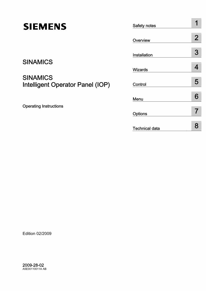
SINAMICS
Operating Instructions · February 2009
Intelligent Operator Panel
SINAMICS IOP

Safety notes 1
Overview
2
Installation
3
Wizards
4
Control
5
Menu
6
Options
7
Technical data
8
SINAMICS
SINAMICS Intelligent Operator Panel (IOP)
Operating Instructions
2009-28-02 A5E00110011A AB
Edition 02/2009
Legal information Warning notice system
This manual contains notices you have to observe in order to ensure your personal safety, as well as to prevent damage to property. The notices referring to your personal safety are highlighted in the manual by a safety alert symbol, notices referring only to property damage have no safety alert symbol. These notices shown below are graded according to the degree of danger.
DANGER indicates that death or severe personal injury will result if proper precautions are not taken.
WARNING indicates that death or severe personal injury may result if proper precautions are not taken.
CAUTION with a safety alert symbol, indicates that minor personal injury can result if proper precautions are not taken.
CAUTION without a safety alert symbol, indicates that property damage can result if proper precautions are not taken.
NOTICE indicates that an unintended result or situation can occur if the corresponding information is not taken into account.
If more than one degree of danger is present, the warning notice representing the highest degree of danger will be used. A notice warning of injury to persons with a safety alert symbol may also include a warning relating to property damage.
Qualified Personnel The device/system may only be set up and used in conjunction with this documentation. Commissioning and operation of a device/system may only be performed by qualified personnel. Within the context of the safety notes in this documentation qualified persons are defined as persons who are authorized to commission, ground and label devices, systems and circuits in accordance with established safety practices and standards.
Proper use of Siemens products Note the following:
WARNING Siemens products may only be used for the applications described in the catalog and in the relevant technical documentation. If products and components from other manufacturers are used, these must be recommended or approved by Siemens. Proper transport, storage, installation, assembly, commissioning, operation and maintenance are required to ensure that the products operate safely and without any problems. The permissible ambient conditions must be adhered to. The information in the relevant documentation must be observed.
Trademarks All names identified by ® are registered trademarks of the Siemens AG. The remaining trademarks in this publication may be trademarks whose use by third parties for their own purposes could violate the rights of the owner.
Disclaimer of Liability We have reviewed the contents of this publication to ensure consistency with the hardware and software described. Since variance cannot be precluded entirely, we cannot guarantee full consistency. However, the information in this publication is reviewed regularly and any necessary corrections are included in subsequent editions.
Siemens AG Industry Sector Postfach 48 48 90026 NÜRNBERG GERMANY
Ordernumber: A5E00110011A AB Ⓟ 03/2009
Copyright © Siemens AG 2009. Technical data subject to change
Intelligent Operator Panel (IOP) Operating Instructions, 2009-28-02, A5E00110011A AB 5
Table of contents
1 Safety notes............................................................................................................................................... 7
1.1 Warnings and cautions ..................................................................................................................7 2 Overview.................................................................................................................................................... 9
2.1 Introduction ....................................................................................................................................9 2.2 Layout and functions....................................................................................................................10 2.3 Screen icons ................................................................................................................................12 2.4 Menu structure .............................................................................................................................13
3 Installation ............................................................................................................................................... 15 3.1 Fitting the IOP ..............................................................................................................................15 3.2 Initial Set-up .................................................................................................................................16
4 Wizards.................................................................................................................................................... 21 4.1 Overview ......................................................................................................................................21 4.2 Wizards ........................................................................................................................................21 4.3 Wiring diagrams ...........................................................................................................................27
5 Control ..................................................................................................................................................... 37 5.1 Overview ......................................................................................................................................37 5.2 Setpoint ........................................................................................................................................37 5.3 Reverse........................................................................................................................................38 5.4 Jog ...............................................................................................................................................38
6 Menu ....................................................................................................................................................... 41 6.1 Overview ......................................................................................................................................41 6.2 Diagnostics...................................................................................................................................42 6.3 Parameters...................................................................................................................................45 6.4 Up/Download................................................................................................................................50 6.5 Extras ...........................................................................................................................................51
7 Options .................................................................................................................................................... 55 7.1 Door mounting kit .........................................................................................................................55 7.2 Hand-held device .........................................................................................................................57
8 Technical data ......................................................................................................................................... 61 8.1 Technical specifications ...............................................................................................................61


Intelligent Operator Panel (IOP) Operating Instructions, 2009-28-02, A5E00110011A AB 7
Safety notes 11.1 Warnings and cautions
Warnings and cautions
WARNING • During commissioning of the Inverter it is essential to ensure that the system is in a safe
and stable state, as some commissioning processes have the potential to start the motor. Therefore it is important to secure any loads and ensure that should the motor start, no potentially dangerous conditions exist.
• The IOP can be fitted to and removed from the inverter while power is applied. • The IOP will set the USS PZD (P2012) length to 4 when connected to the inverter.

Intelligent Operator Panel (IOP) Operating Instructions, 2009-28-02, A5E00110011A AB 9
Overview 22.1 Introduction
Introduction The Intelligent Operator Panel (IOP) has been designed to enhance the interface and communications capabilities of SINAMICS Inverters. The IOP connects to the Inverter through an RS232 interface. It has been designed to automatically recognise the following devices from the SINAMICS range: ● SINAMICS G120 CU240 PN ● SINAMICS G120 CU240 PN-F ● SINAMICS G120 CU240S ● SINAMICS G120 CU240S DP ● SINAMICS G120 CU240S DP-F ● SINAMICS G120 CU240E ● SINAMICS G120D ● SINAMICS G120 CU230P-2 HVAC ● SINAMICS G120 CU230P-2 CAN ● SINAMICS G120 CU230P-2 DP ● SINAMICS ET200S ● SINAMICS ET200 PRO The IOP provides support, using the USB connection utilizing a PC for the following functions: ● Downloading of wizards ● Downloading additional languages
Note IOP functional suppport • Devices prior to version 3.0 firmware may not be fully supported by the IOP. • The actual menu structure and functionality of the IOP will be influenced by the
following factors: – The software version and type of Control Unit to which the IOP is fitted. – The firmware and software version of the IOP. – The selected functional group filtering of the parameters.
Overview 2.2 Layout and functions
Intelligent Operator Panel (IOP) 10 Operating Instructions, 2009-28-02, A5E00110011A AB
2.2 Layout and functions
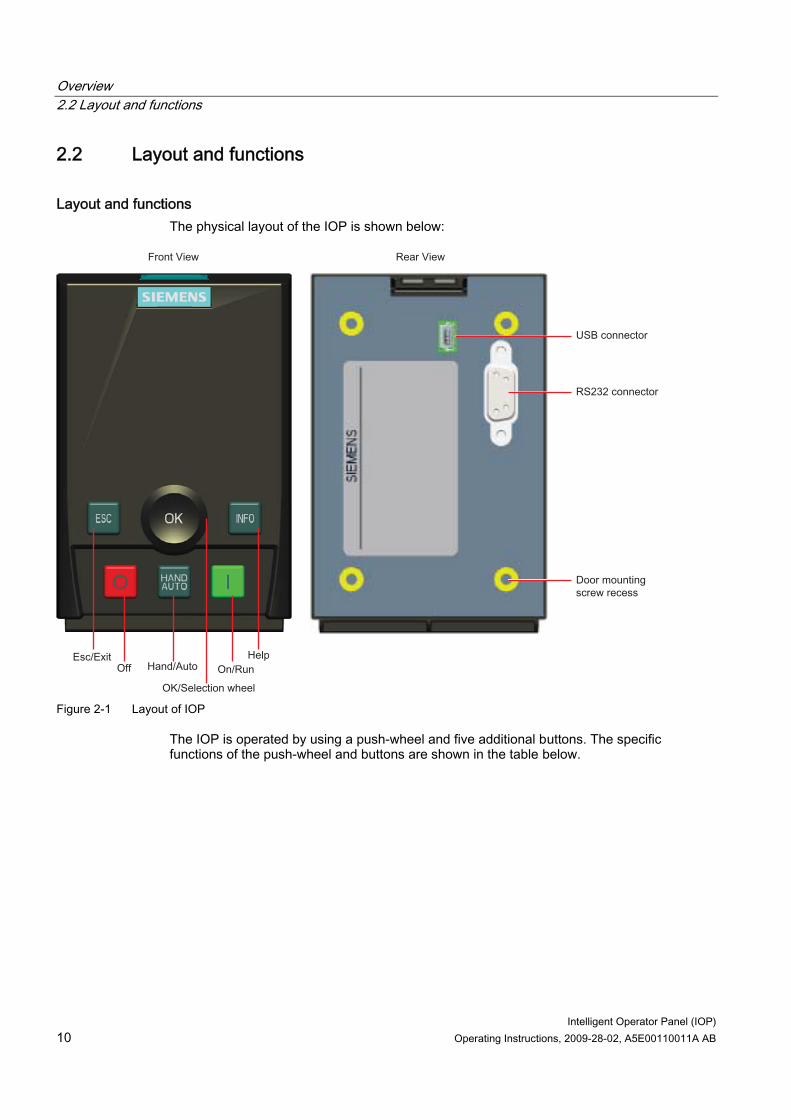
Layout and functions The physical layout of the IOP is shown below:
Figure 2-1 Layout of IOP
The IOP is operated by using a push-wheel and five additional buttons. The specific functions of the push-wheel and buttons are shown in the table below.
Overview 2.2 Layout and functions
Intelligent Operator Panel (IOP) Operating Instructions, 2009-28-02, A5E00110011A AB 11
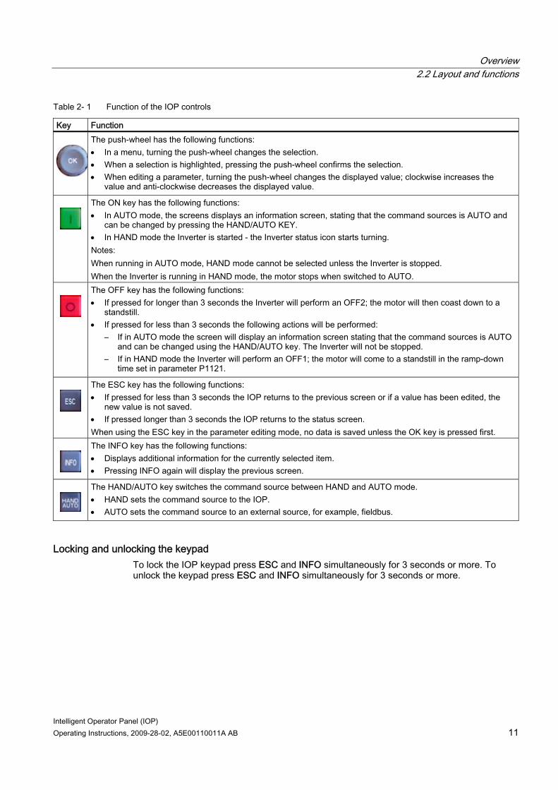
Table 2- 1 Function of the IOP controls
Key Function The push-wheel has the following functions:
• In a menu, turning the push-wheel changes the selection. • When a selection is highlighted, pressing the push-wheel confirms the selection. • When editing a parameter, turning the push-wheel changes the displayed value; clockwise increases the
value and anti-clockwise decreases the displayed value.
The ON key has the following functions: • In AUTO mode, the screens displays an information screen, stating that the command sources is AUTO and
can be changed by pressing the HAND/AUTO KEY. • In HAND mode the Inverter is started - the Inverter status icon starts turning. Notes: When running in AUTO mode, HAND mode cannot be selected unless the Inverter is stopped. When the Inverter is running in HAND mode, the motor stops when switched to AUTO.
The OFF key has the following functions: • If pressed for longer than 3 seconds the Inverter will perform an OFF2; the motor will then coast down to a
standstill. • If pressed for less than 3 seconds the following actions will be performed:
– If in AUTO mode the screen will display an information screen stating that the command sources is AUTO and can be changed using the HAND/AUTO key. The Inverter will not be stopped.
– If in HAND mode the Inverter will perform an OFF1; the motor will come to a standstill in the ramp-down time set in parameter P1121.
The ESC key has the following functions: • If pressed for less than 3 seconds the IOP returns to the previous screen or if a value has been edited, the
new value is not saved. • If pressed longer than 3 seconds the IOP returns to the status screen. When using the ESC key in the parameter editing mode, no data is saved unless the OK key is pressed first.
The INFO key has the following functions: • Displays additional information for the currently selected item. • Pressing INFO again will display the previous screen.
The HAND/AUTO key switches the command source between HAND and AUTO mode. • HAND sets the command source to the IOP. • AUTO sets the command source to an external source, for example, fieldbus.
Locking and unlocking the keypad To lock the IOP keypad press ESC and INFO simultaneously for 3 seconds or more. To unlock the keypad press ESC and INFO simultaneously for 3 seconds or more.
Overview 2.3 Screen icons
Intelligent Operator Panel (IOP) 12 Operating Instructions, 2009-28-02, A5E00110011A AB
2.3 Screen icons
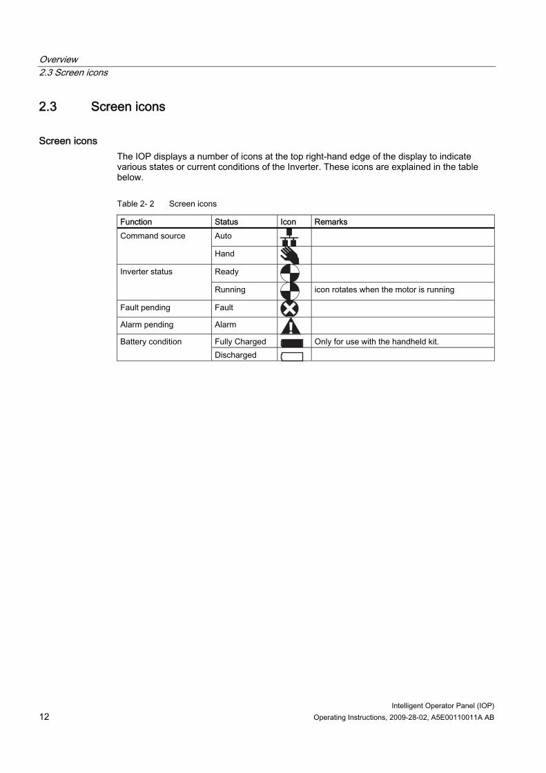
Screen icons The IOP displays a number of icons at the top right-hand edge of the display to indicate various states or current conditions of the Inverter. These icons are explained in the table below.
Table 2- 2 Screen icons
Function Status Icon Remarks Auto Command source
Hand
Ready Inverter status
Running icon rotates when the motor is running
Fault pending Fault
Alarm pending Alarm
Fully Charged Only for use with the handheld kit. Battery condition Discharged
Overview 2.4 Menu structure
Intelligent Operator Panel (IOP) Operating Instructions, 2009-28-02, A5E00110011A AB 13
2.4 Menu structure
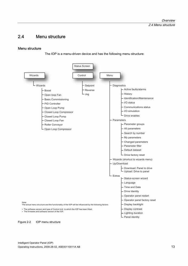
Menu structure The IOP is a menu-driven device and has the following menu structure:
Figure 2-2 IOP menu structure

Intelligent Operator Panel (IOP) Operating Instructions, 2009-28-02, A5E00110011A AB 15
Installation 33.1 Fitting the IOP
Fitting the IOP to the Control Unit
CAUTION IOP power supply The IOP has no internal power supply and derives its power directly from the Control Unit of the Inverter through the RS232 interface. The IOP can also be connected to a PC and derives its power through the USB connection.
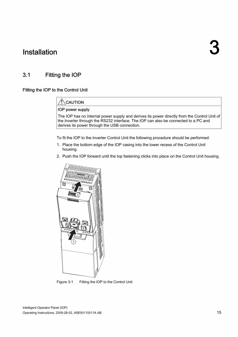
To fit the IOP to the Inverter Control Unit the following procedure should be performed: 1. Place the bottom edge of the IOP casing into the lower recess of the Control Unit
housing. 2. Push the IOP forward until the top fastening clicks into place on the Control Unit housing.
Figure 3-1 Fitting the IOP to the Control Unit
Installation 3.2 Initial Set-up
Intelligent Operator Panel (IOP) 16 Operating Instructions, 2009-28-02, A5E00110011A AB
3.2 Initial Set-up
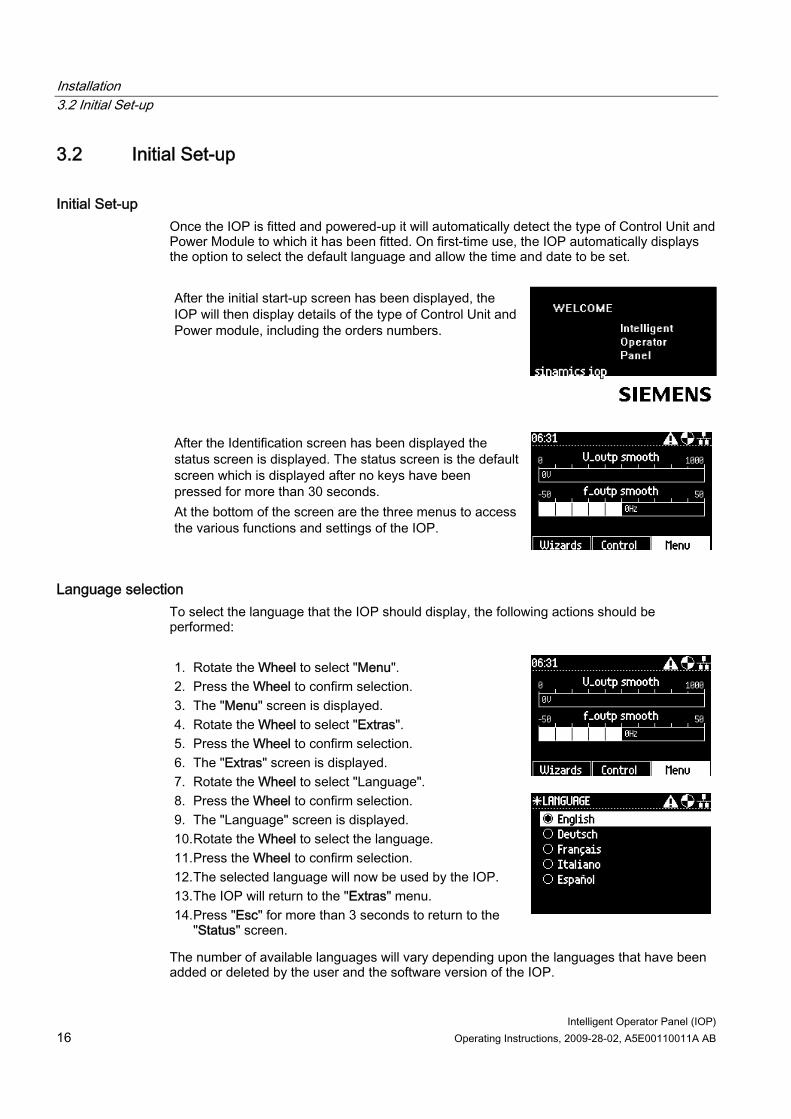
Initial Set-up Once the IOP is fitted and powered-up it will automatically detect the type of Control Unit and Power Module to which it has been fitted. On first-time use, the IOP automatically displays the option to select the default language and allow the time and date to be set. After the initial start-up screen has been displayed, the IOP will then display details of the type of Control Unit and Power module, including the orders numbers.
After the Identification screen has been displayed the status screen is displayed. The status screen is the default screen which is displayed after no keys have been pressed for more than 30 seconds. At the bottom of the screen are the three menus to access the various functions and settings of the IOP.
Language selection To select the language that the IOP should display, the following actions should be performed:
1. Rotate the Wheel to select "Menu". 2. Press the Wheel to confirm selection. 3. The "Menu" screen is displayed. 4. Rotate the Wheel to select "Extras". 5. Press the Wheel to confirm selection. 6. The "Extras" screen is displayed. 7. Rotate the Wheel to select "Language". 8. Press the Wheel to confirm selection. 9. The "Language" screen is displayed. 10. Rotate the Wheel to select the language. 11. Press the Wheel to confirm selection. 12. The selected language will now be used by the IOP. 13. The IOP will return to the "Extras" menu. 14. Press "Esc" for more than 3 seconds to return to the
"Status" screen.
The number of available languages will vary depending upon the languages that have been added or deleted by the user and the software version of the IOP.
Installation 3.2 Initial Set-up
Intelligent Operator Panel (IOP) Operating Instructions, 2009-28-02, A5E00110011A AB 17
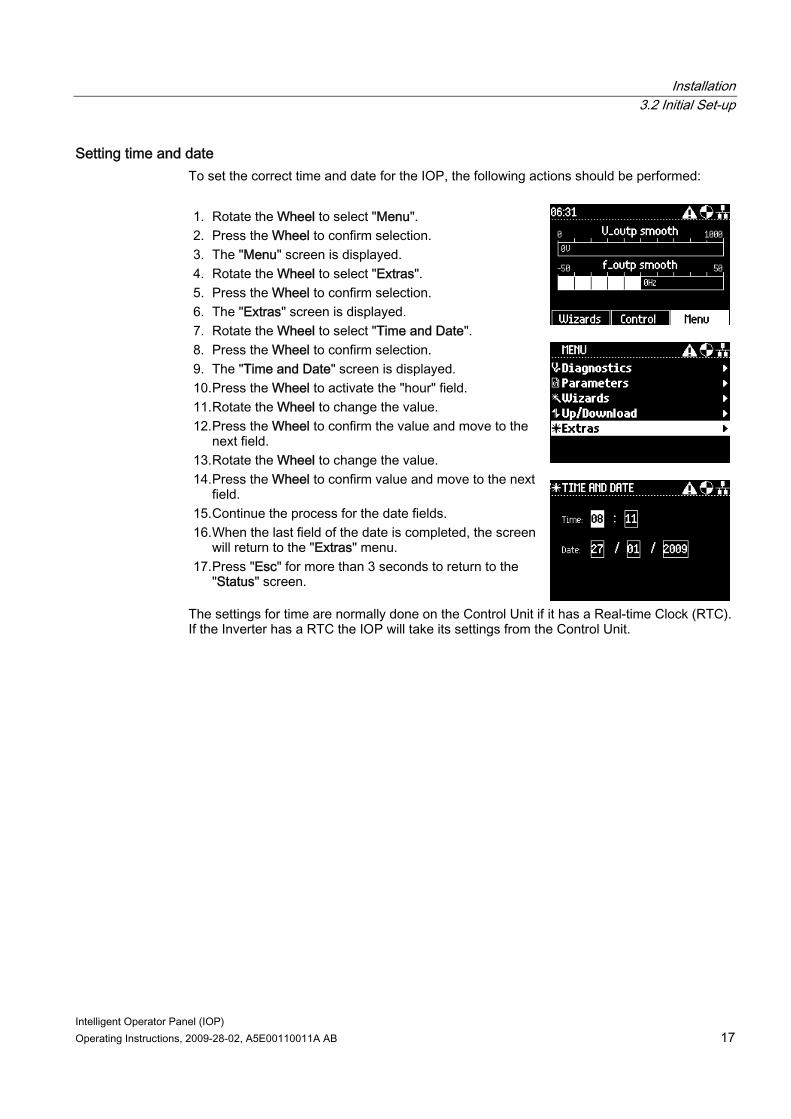
Setting time and date To set the correct time and date for the IOP, the following actions should be performed: 1. Rotate the Wheel to select "Menu". 2. Press the Wheel to confirm selection. 3. The "Menu" screen is displayed. 4. Rotate the Wheel to select "Extras". 5. Press the Wheel to confirm selection. 6. The "Extras" screen is displayed. 7. Rotate the Wheel to select "Time and Date". 8. Press the Wheel to confirm selection. 9. The "Time and Date" screen is displayed. 10. Press the Wheel to activate the "hour" field. 11. Rotate the Wheel to change the value. 12. Press the Wheel to confirm the value and move to the
next field. 13. Rotate the Wheel to change the value. 14. Press the Wheel to confirm value and move to the next
field. 15. Continue the process for the date fields. 16. When the last field of the date is completed, the screen
will return to the "Extras" menu. 17. Press "Esc" for more than 3 seconds to return to the
"Status" screen.
The settings for time are normally done on the Control Unit if it has a Real-time Clock (RTC). If the Inverter has a RTC the IOP will take its settings from the Control Unit.
Installation 3.2 Initial Set-up
Intelligent Operator Panel (IOP) 18 Operating Instructions, 2009-28-02, A5E00110011A AB
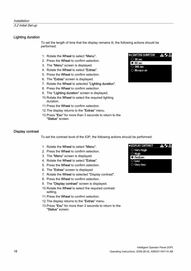
Lighting duration To set the length of time that the display remains lit, the following actions should be performed: 1. Rotate the Wheel to select "Menu". 2. Press the Wheel to confirm selection. 3. The "Menu" screen is displayed. 4. Rotate the Wheel to select "Extras". 5. Press the Wheel to confirm selection. 6. The "Extras" screen is displayed. 7. Rotate the Wheel to selected "Lighting duration". 8. Press the Wheel to confirm selection. 9. The "Lighting duration" screen is displayed. 10. Rotate the Wheel to select the required lighting
duration. 11. Press the Wheel to confirm selection. 12. The display returns to the "Extras" menu. 13. Press "Esc" for more than 3 seconds to return to the
"Status" screen.
Display contrast To set the contrast level of the IOP, the following actions should be performed: 1. Rotate the Wheel to select "Menu". 2. Press the Wheel to confirm selection. 3. The "Menu" screen is displayed. 4. Rotate the Wheel to select "Extras". 5. Press the Wheel to confirm selection. 6. The "Extras" screen is displayed. 7. Rotate the Wheel to selected "Display contrast". 8. Press the Wheel to confirm selection. 9. The "Display contrast" screen is displayed. 10. Rotate the Wheel to select the required contrast
setting. 11. Press the Wheel to confirm selection. 12. The display returns to the "Extras" menu. 13. Press "Esc" for more than 3 seconds to return to the
"Status" screen.
Installation 3.2 Initial Set-up
Intelligent Operator Panel (IOP) Operating Instructions, 2009-28-02, A5E00110011A AB 19
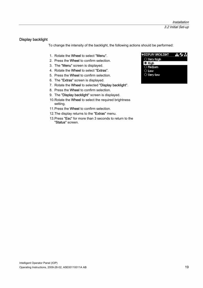
Display backlight To change the intensity of the backlight, the following actions should be performed: 1. Rotate the Wheel to select "Menu". 2. Press the Wheel to confirm selection. 3. The "Menu" screen is displayed. 4. Rotate the Wheel to select "Extras". 5. Press the Wheel to confirm selection. 6. The "Extras" screen is displayed. 7. Rotate the Wheel to selected "Display backlight". 8. Press the Wheel to confirm selection. 9. The "Display backlight" screen is displayed. 10. Rotate the Wheel to select the required brightness
setting. 11. Press the Wheel to confirm selection. 12. The display returns to the "Extras" menu. 13. Press "Esc" for more than 3 seconds to return to the
"Status" screen.


Intelligent Operator Panel (IOP) Operating Instructions, 2009-28-02, A5E00110011A AB 21
Wizards 44.1 Overview
Overview The IOP wizards are question-driven macros that assist the user to set-up various functions and applications of the Inverter.
WARNING Commissioning the Inverter During commissioning of the Inverter it is essential to ensure that the system is in a safe and stable state, as some commissioning processes have the potential to start the motor. Therefore it is important to secure any loads and ensure that should the motor start, no potentially dangerous conditions exist. Datasets The wizards use the default Drive Datasets (DDS0 and CDS0), if the default datasets are changed to the other datasets available, the wizards may not function correctly.
4.2 Wizards
Wizards There are several wizards which allow the user to set-up various functions and commission the Inverter. An example of the type of wizards are given below: ● Boost ● Open-loop fan ● Basic commissioning ● PID controller ● Open-loop pump ● Closed-loop compressor ● Closed-loop pump ● Roller conveyor ● Open-loop compressor
Wizards 4.2 Wizards
Intelligent Operator Panel (IOP) 22 Operating Instructions, 2009-28-02, A5E00110011A AB
The following is an outline of the various wizards; the relevant wiring diagrams, if required are contained in the "Wiring diagrams" section in this chapter.
Note Wizards The actual menu structure and the functionality of the IOP will be influenced by the following factors: • The software version and type of Control Unit to which the IOP has been fitted. • The firmware and software version of the IOP. • The Roller conveyor wizard requires a fieldbus compatible Control Unit
(PROFIBUS/PROFINET). SINAMICS ET200S (Pro) and SINAMICS G120D Inverters The Roller conveyor wizard is the only application wizard available for SINAMICS ET200S (Pro) and SINAMICS G120D Inverters.
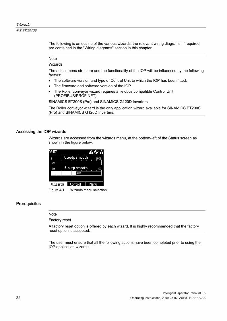
Accessing the IOP wizards Wizards are accessed from the wizards menu, at the bottom-left of the Status screen as shown in the figure below.
Figure 4-1 Wizards menu selection
Prerequisites
Note Factory reset A factory reset option is offered by each wizard. It is highly recommended that the factory reset option is accepted.
The user must ensure that all the following actions have been completed prior to using the IOP application wizards:
Wizards 4.2 Wizards
Intelligent Operator Panel (IOP) Operating Instructions, 2009-28-02, A5E00110011A AB 23
● All necessary equipment is available and installed correctly, according to the relevant wiring diagram for the specific application wizard.
● All wiring of the Inverter, motor and any other devices used within the application has been completed in accordance with the wiring diagrams included in the appropriate section of this manual.
● All components of the system have been tested to ensure their correct and safe installation.
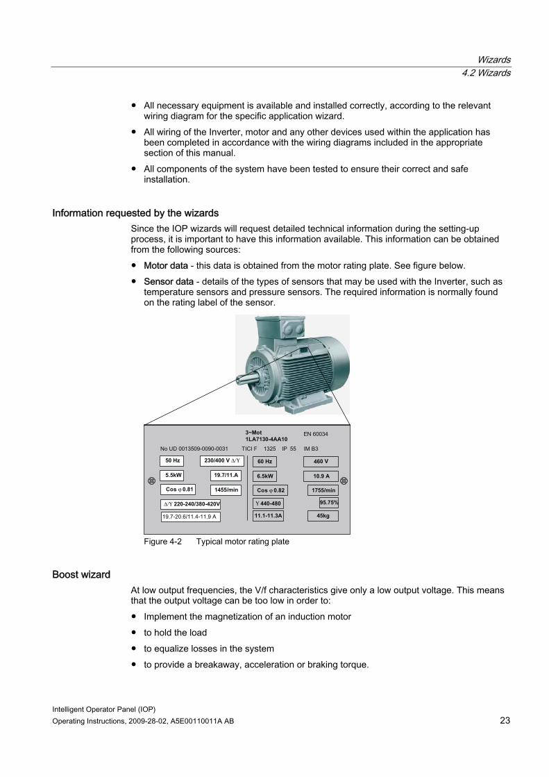
Information requested by the wizards Since the IOP wizards will request detailed technical information during the setting-up process, it is important to have this information available. This information can be obtained from the following sources: ● Motor data - this data is obtained from the motor rating plate. See figure below. ● Sensor data - details of the types of sensors that may be used with the Inverter, such as
temperature sensors and pressure sensors. The required information is normally found on the rating label of the sensor.
60 Hz 460 V
11.1-11.3A
EN 60034 3~Mot1LA7130-4AA10
No UD 0013509-0090-0031 TICI F 1325 IP 55 IM B3
230/400 V Δ/Υ 50 Hz
Cos ϕ 0.82
6.5kW 10.9 A
95.75%
1755/min
45kg
Υ 440-480
19.7/11.A
1455/min
5.5kW
Cos ϕ 0.81
Δ/Υ 220-240/380-420V
19.7-20.6/11.4-11.9 A
Figure 4-2 Typical motor rating plate
Boost wizard At low output frequencies, the V/f characteristics give only a low output voltage. This means that the output voltage can be too low in order to: ● Implement the magnetization of an induction motor ● to hold the load ● to equalize losses in the system ● to provide a breakaway, acceleration or braking torque.
Wizards 4.2 Wizards
Intelligent Operator Panel (IOP) 24 Operating Instructions, 2009-28-02, A5E00110011A AB
The output voltage can be increased (boosted) in the Inverter using the boost function. The Boost settings wizard guide the user through the correct setting of the boost function.
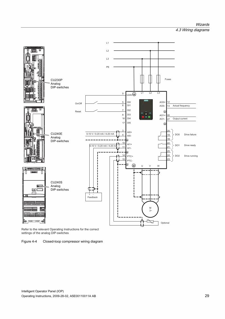
Open-loop fan wizard This is a basic fan application where the fan is under the control of the Inverter. The system comprises of the following components: ● Control Module ● Power Module ● Motor ● Fan ● Belt monitoring sensor (optional) ● Motor temperature sensor (optional)
Basic commissioning wizard The basic commissioning of the Inverter and motor comprises a number of processes. The processes are as follows: ● Quick commissioning ● Vector control mode ● Calculation of motor and control data The wizard will guide the user through the basic commissioning process by presenting a number of screens where the user can choose the necessary options and values to commission the Inverter and motor. At the conclusion of the basic commissioning process, the data can be saved to the Inverters memory.
PID controller wizard Closed-loop control is widely used in industrial applications to control a wide variety of processes. A simple closed-loop control uses a feedback signal from the process (such as, temperature, pressure and speed) and a desired value or setpoint. The control system compares the two values and derives an error signal. The error signal is used to control the Inverter and motor to reduce the error. The error signal processing can be very complex because of the delays in the system. The error signal is processed using a Proportional and Integral differential (PID) controller whose parameters can be adjusted to optimize the performance and stability of the system. The PID controller wizard guide the user through the PID setting-up process.
Open-loop pump wizard The purpose of this application is to maintain a constant level of fluid in a pumping system and reacting to maintain the pre-determined level even if fluid is being drawn from the system. The analog input is used to set the frequency setpoint.
Wizards 4.2 Wizards
Intelligent Operator Panel (IOP) Operating Instructions, 2009-28-02, A5E00110011A AB 25
The system comprises the following components: ● Control Module ● Power Module ● Motor ● Pump ● Motor temperature sensor (optional) ● Level sensor (dry run protection - optional).
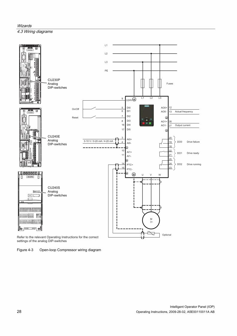
Closed-loop compressor wizard A constant pressure is required to be maintained within a system utilizing the minimum use of energy. The pressure in the system is monitored using the PID controller and if the pressure remains constant then the Inverter will run the system at the minimum frequency to maintain the pressure. The setpoints are controlled by analog input 0. The feedback from the system are received from the pressure sensor utilizing analog input 1. This feedback is then used by the Inverter to react to changes in the system pressure. The on/off and reset commands are controlled using digital inputs 0 and 1 respectively. The general monitoring of the condition of the Inverter is achieved using digital outputs 0, 1 and 2 for drive failure, drive ready and drive running respectively. The system will comprise of the following components: ● Control Module ● Power Module ● Motor ● Compressor ● Pressure sensor ● Motor temperature sensor (optional).
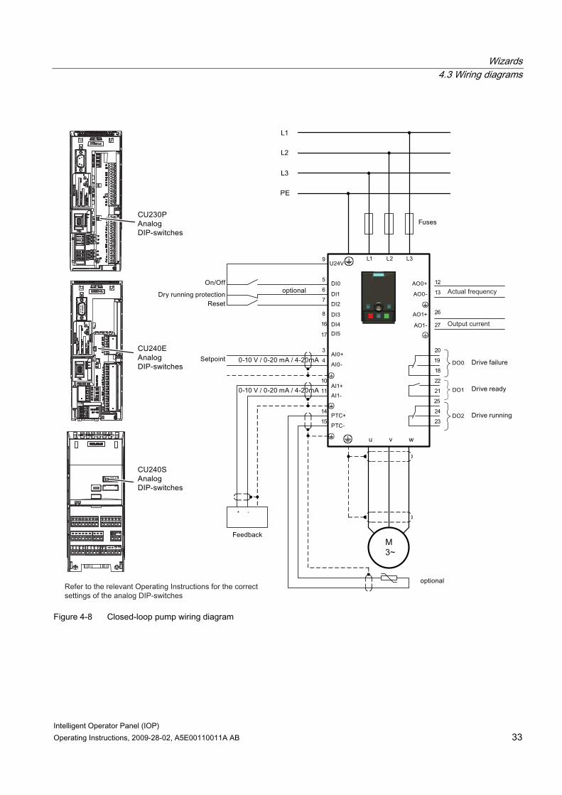
Closed-loop pump wizard The closed-loop application allows for the fluid in a tank to be directly monitored using the PID control function. The system comprises the following components: ● Control Unit ● Power Module ● Motor ● Pump ● Feedback sensor
Wizards 4.2 Wizards
Intelligent Operator Panel (IOP) 26 Operating Instructions, 2009-28-02, A5E00110011A AB
● Level sensor (dry run protection - optional) ● Motor temperature sensor (optional).
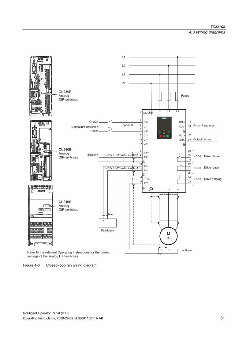
Closed-loop fan wizard The purpose of the closed-loop controlled fan application is to maintain a constant airflow within a ventilation system, utilizing as little energy as possible. A specific airflow and pressure for the fan system is set within the Inverter and these values are directly monitored using the PID controller. Depending on a decrease or increase in pressure readings, the Inverter will increase or decrease the speed of the fan accordingly. The system comprises the following components: ● Control Module ● Power Module ● Motor ● Fan ● Feedback sensor ● Motor temperature sensor (optional).
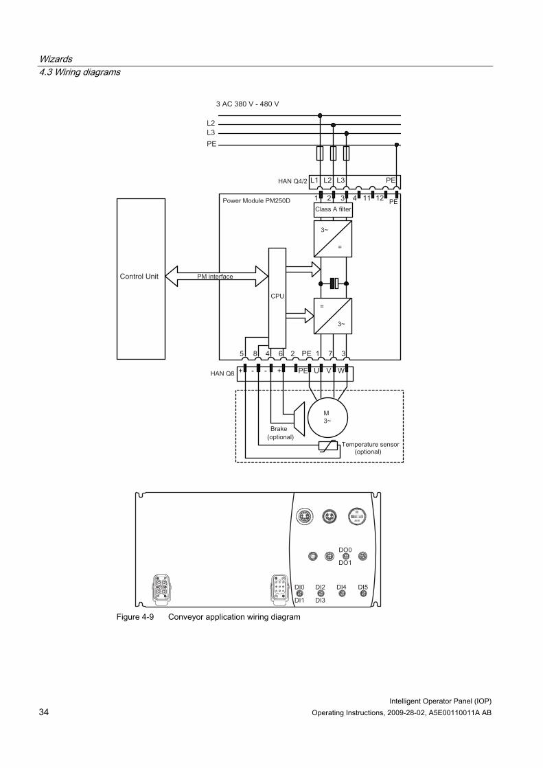
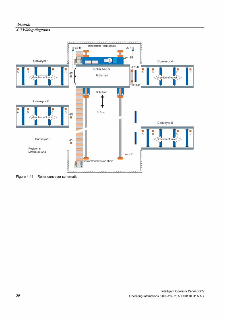
Roller conveyor wizard This wizard can be used for the typical material handling applications, such as conveyor belts, roller conveyors and turn-tables. The sensors are directly connected to the Inverter to allow their individual status to be sent to the controlling PLC. The system will comprise of the following components: ● Control Module (with fieldbus interface) ● Power Module ● Geared motor ● Initiators (digital) ● Mechanical brake ● Motor temperature sensor (optional).
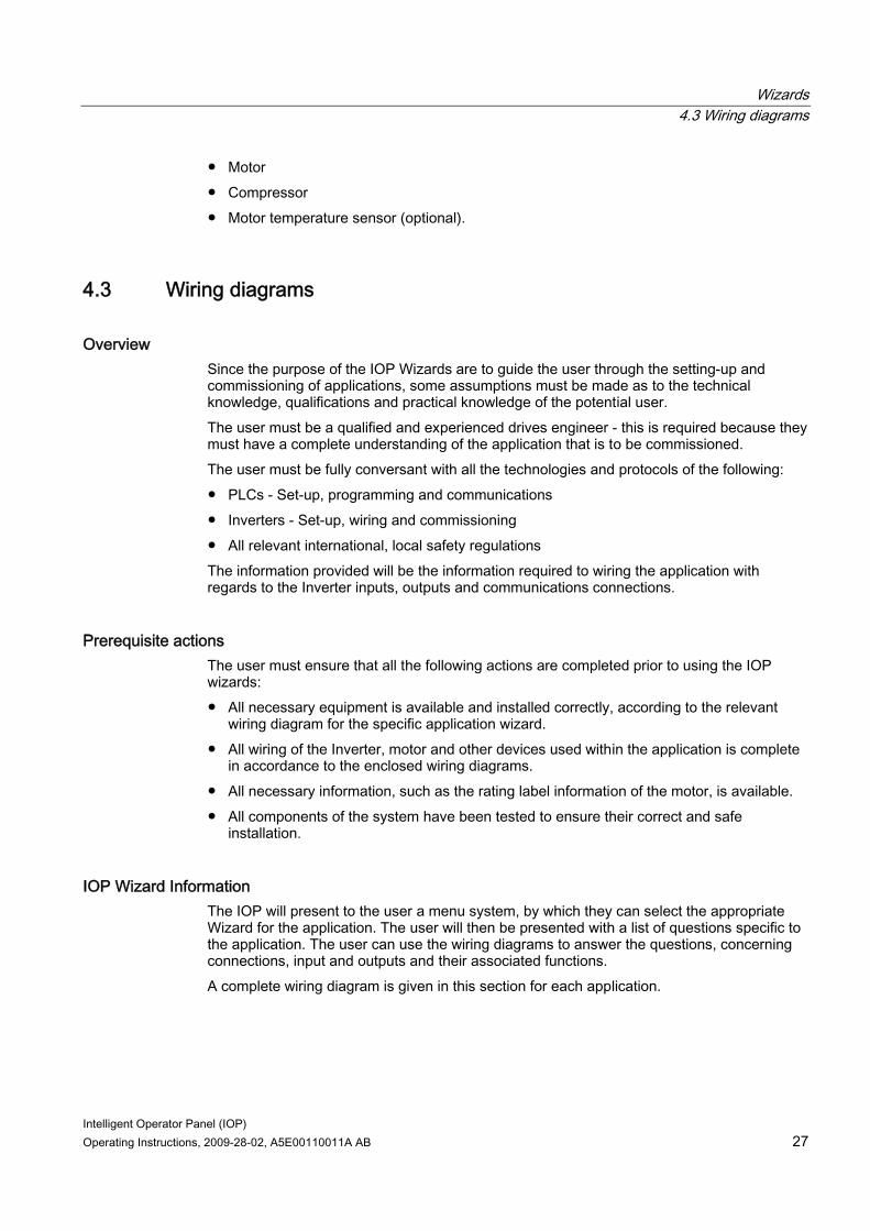
Open-loop compressor wizard The Inverter is used to control the output pressure of a compressor to ensure that it adapts to the varying volume of gas that is required to be compressed. Compressing the gas involves reducing the volume and increasing the pressure within the container to compress the gas. The setpoint is controlled by the analog inputs. The system comprises of the following components: ● Control Module ● Power Module
Wizards 4.3 Wiring diagrams
Intelligent Operator Panel (IOP) Operating Instructions, 2009-28-02, A5E00110011A AB 27
● Motor ● Compressor ● Motor temperature sensor (optional).
4.3 Wiring diagrams
Overview Since the purpose of the IOP Wizards are to guide the user through the setting-up and commissioning of applications, some assumptions must be made as to the technical knowledge, qualifications and practical knowledge of the potential user. The user must be a qualified and experienced drives engineer - this is required because they must have a complete understanding of the application that is to be commissioned. The user must be fully conversant with all the technologies and protocols of the following: ● PLCs - Set-up, programming and communications ● Inverters - Set-up, wiring and commissioning ● All relevant international, local safety regulations The information provided will be the information required to wiring the application with regards to the Inverter inputs, outputs and communications connections.
Prerequisite actions The user must ensure that all the following actions are completed prior to using the IOP wizards: ● All necessary equipment is available and installed correctly, according to the relevant
wiring diagram for the specific application wizard. ● All wiring of the Inverter, motor and other devices used within the application is complete
in accordance to the enclosed wiring diagrams. ● All necessary information, such as the rating label information of the motor, is available. ● All components of the system have been tested to ensure their correct and safe
installation.
IOP Wizard Information The IOP will present to the user a menu system, by which they can select the appropriate Wizard for the application. The user will then be presented with a list of questions specific to the application. The user can use the wiring diagrams to answer the questions, concerning connections, input and outputs and their associated functions. A complete wiring diagram is given in this section for each application.
Wizards 4.3 Wiring diagrams
Intelligent Operator Panel (IOP) 28 Operating Instructions, 2009-28-02, A5E00110011A AB
Figure 4-3 Open-loop Compressor wiring diagram
Wizards 4.3 Wiring diagrams
Intelligent Operator Panel (IOP) Operating Instructions, 2009-28-02, A5E00110011A AB 29
Figure 4-4 Closed-loop compressor wiring diagram
Wizards 4.3 Wiring diagrams
Intelligent Operator Panel (IOP) 30 Operating Instructions, 2009-28-02, A5E00110011A AB
3
L1
L2
L3
PE
u v w
M~
Figure 4-5 Open-loop fan wiring diagram
Wizards 4.3 Wiring diagrams
Intelligent Operator Panel (IOP) Operating Instructions, 2009-28-02, A5E00110011A AB 31
+ -
3
L1
L2
L3
PE
u v w
M~
Figure 4-6 Closed-loop fan wiring diagram

Wizards 4.3 Wiring diagrams
Intelligent Operator Panel (IOP) 32 Operating Instructions, 2009-28-02, A5E00110011A AB
3
L1
L2
L3
PE
u v w
M~
Figure 4-7 Open-loop pump wiring diagram
Wizards 4.3 Wiring diagrams
Intelligent Operator Panel (IOP) Operating Instructions, 2009-28-02, A5E00110011A AB 33
+ -
3
L1
L2
L3
PE
u v w
M~
Figure 4-8 Closed-loop pump wiring diagram
Wizards 4.3 Wiring diagrams
Intelligent Operator Panel (IOP) 34 Operating Instructions, 2009-28-02, A5E00110011A AB
Figure 4-9 Conveyor application wiring diagram
Wizards 4.3 Wiring diagrams
Intelligent Operator Panel (IOP) Operating Instructions, 2009-28-02, A5E00110011A AB 35
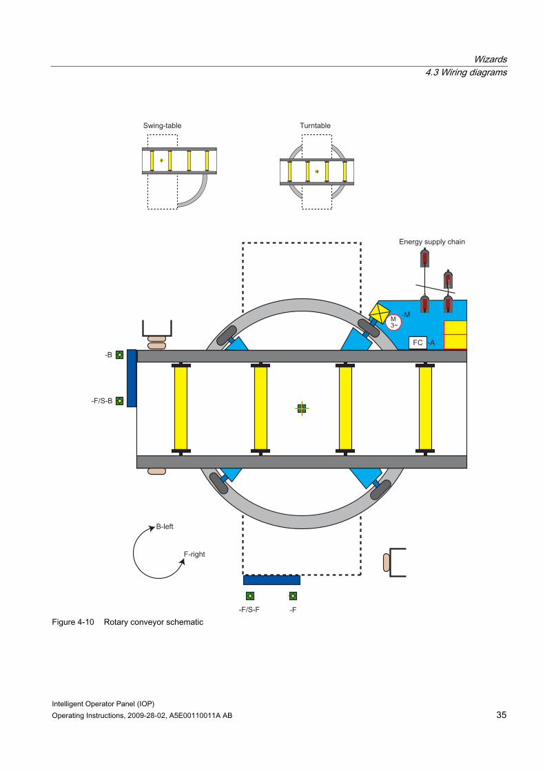
Figure 4-10 Rotary conveyor schematic
Wizards 4.3 Wiring diagrams
Intelligent Operator Panel (IOP) 36 Operating Instructions, 2009-28-02, A5E00110011A AB
Figure 4-11 Roller conveyor schematic
Intelligent Operator Panel (IOP) Operating Instructions, 2009-28-02, A5E00110011A AB 37
Control 55.1 Overview
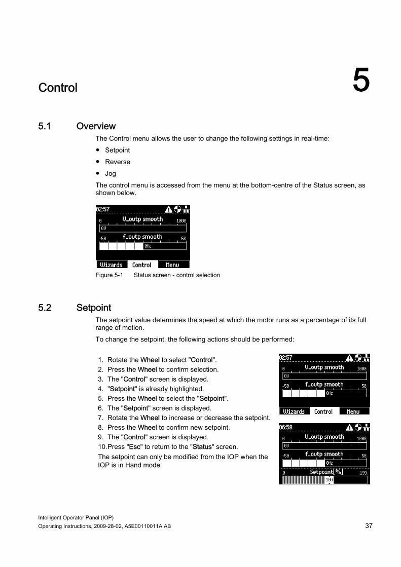
The Control menu allows the user to change the following settings in real-time: ● Setpoint ● Reverse ● Jog The control menu is accessed from the menu at the bottom-centre of the Status screen, as shown below.
Figure 5-1 Status screen - control selection
5.2 Setpoint The setpoint value determines the speed at which the motor runs as a percentage of its full range of motion. To change the setpoint, the following actions should be performed: 1. Rotate the Wheel to select "Control". 2. Press the Wheel to confirm selection. 3. The "Control" screen is displayed. 4. "Setpoint" is already highlighted. 5. Press the Wheel to select the "Setpoint". 6. The "Setpoint" screen is displayed. 7. Rotate the Wheel to increase or decrease the setpoint. 8. Press the Wheel to confirm new setpoint. 9. The "Control" screen is displayed. 10. Press "Esc" to return to the "Status" screen. The setpoint can only be modified from the IOP when the IOP is in Hand mode.
Control 5.3 Reverse
Intelligent Operator Panel (IOP) 38 Operating Instructions, 2009-28-02, A5E00110011A AB
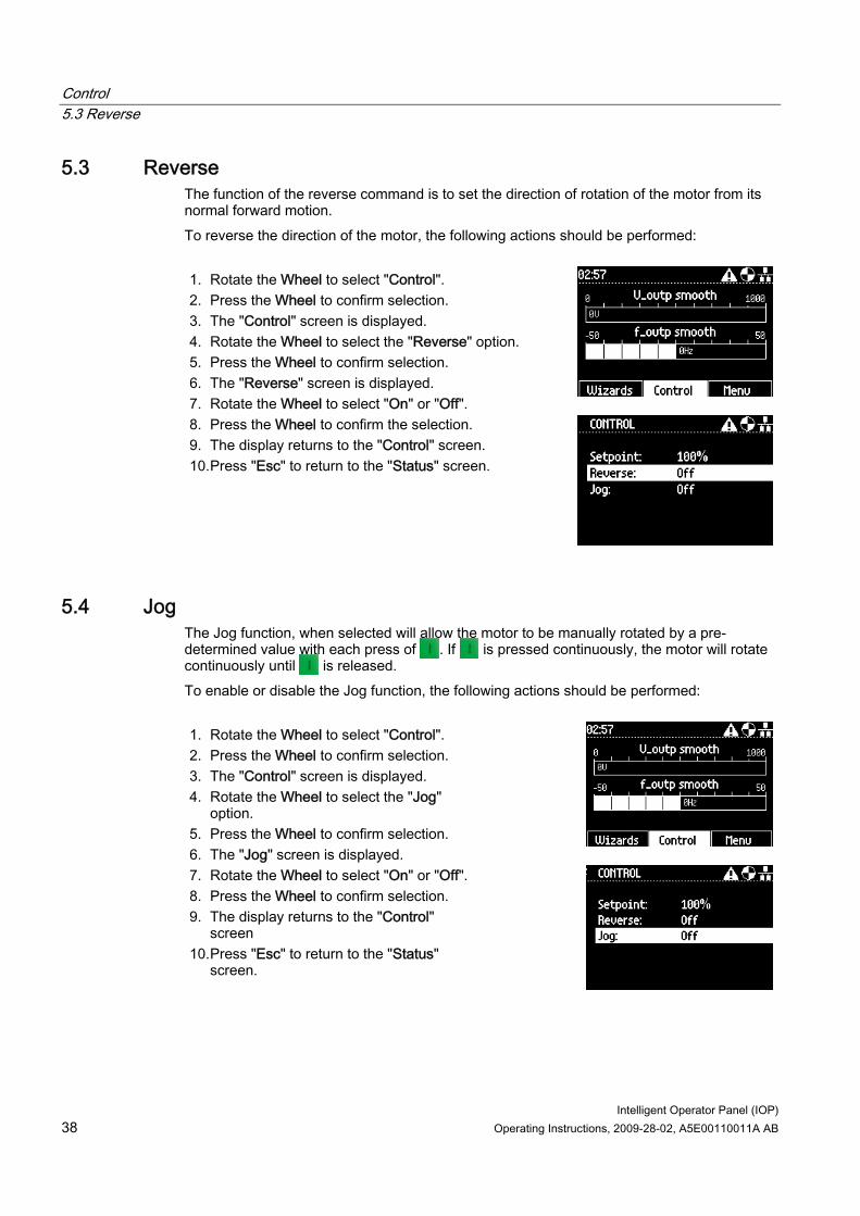
5.3 Reverse The function of the reverse command is to set the direction of rotation of the motor from its normal forward motion. To reverse the direction of the motor, the following actions should be performed: 1. Rotate the Wheel to select "Control". 2. Press the Wheel to confirm selection. 3. The "Control" screen is displayed. 4. Rotate the Wheel to select the "Reverse" option. 5. Press the Wheel to confirm selection. 6. The "Reverse" screen is displayed. 7. Rotate the Wheel to select "On" or "Off". 8. Press the Wheel to confirm the selection. 9. The display returns to the "Control" screen. 10. Press "Esc" to return to the "Status" screen.
5.4 Jog The Jog function, when selected will allow the motor to be manually rotated by a pre-determined value with each press of . If is pressed continuously, the motor will rotate continuously until is released. To enable or disable the Jog function, the following actions should be performed: 1. Rotate the Wheel to select "Control". 2. Press the Wheel to confirm selection. 3. The "Control" screen is displayed. 4. Rotate the Wheel to select the "Jog"
option. 5. Press the Wheel to confirm selection. 6. The "Jog" screen is displayed. 7. Rotate the Wheel to select "On" or "Off". 8. Press the Wheel to confirm selection. 9. The display returns to the "Control"
screen 10. Press "Esc" to return to the "Status"
screen.

Control 5.4 Jog
Intelligent Operator Panel (IOP) Operating Instructions, 2009-28-02, A5E00110011A AB 39
Note Selection of Jog frequencies It is important that the Jog parameters P1058 and P1059 are set to the required frequencies for the users application. When the Jog left and Jog right (Jog1 and Jog 2) have been set; it is necessary to press the "INFO" key to select the other jog mode.

Intelligent Operator Panel (IOP) Operating Instructions, 2009-28-02, A5E00110011A AB 41
Menu 66.1 Overview
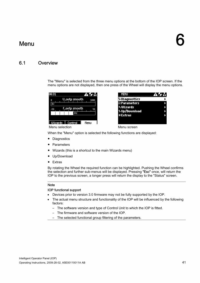
The "Menu" is selected from the three menu options at the bottom of the IOP screen. If the menu options are not displayed, then one press of the Wheel will display the menu options.
Menu selection Menu screen When the "Menu" option is selected the following functions are displayed: ● Diagnostics ● Parameters ● Wizards (this is a shortcut to the main Wizards menu) ● Up/Download ● Extras By rotating the Wheel the required function can be highlighted. Pushing the Wheel confirms the selection and further sub-menus will be displayed. Pressing "Esc" once, will return the IOP to the previous screen, a longer press will return the display to the "Status" screen.
Note IOP functional support • Devices prior to version 3.0 firmware may not be fully supported by the IOP. • The actual menu structure and functionality of the IOP will be influenced by the following
factors: – The software version and type of Control Unit to which the IOP is fitted. – The firmware and software version of the IOP. – The selected functional group filtering of the parameters.
Menu 6.2 Diagnostics
Intelligent Operator Panel (IOP) 42 Operating Instructions, 2009-28-02, A5E00110011A AB
6.2 Diagnostics
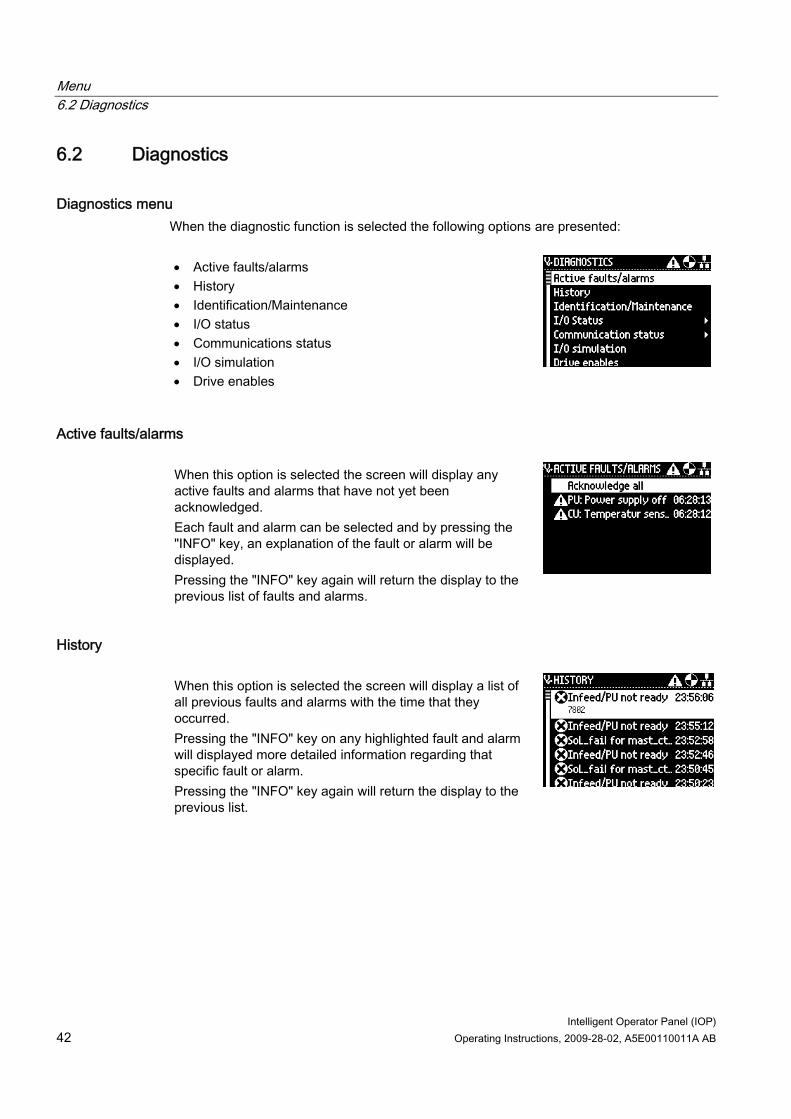
Diagnostics menu When the diagnostic function is selected the following options are presented: • Active faults/alarms • History • Identification/Maintenance • I/O status • Communications status • I/O simulation • Drive enables
Active faults/alarms When this option is selected the screen will display any active faults and alarms that have not yet been acknowledged. Each fault and alarm can be selected and by pressing the "INFO" key, an explanation of the fault or alarm will be displayed. Pressing the "INFO" key again will return the display to the previous list of faults and alarms.
History When this option is selected the screen will display a list of all previous faults and alarms with the time that they occurred. Pressing the "INFO" key on any highlighted fault and alarm will displayed more detailed information regarding that specific fault or alarm. Pressing the "INFO" key again will return the display to the previous list.
Menu 6.2 Diagnostics
Intelligent Operator Panel (IOP) Operating Instructions, 2009-28-02, A5E00110011A AB 43
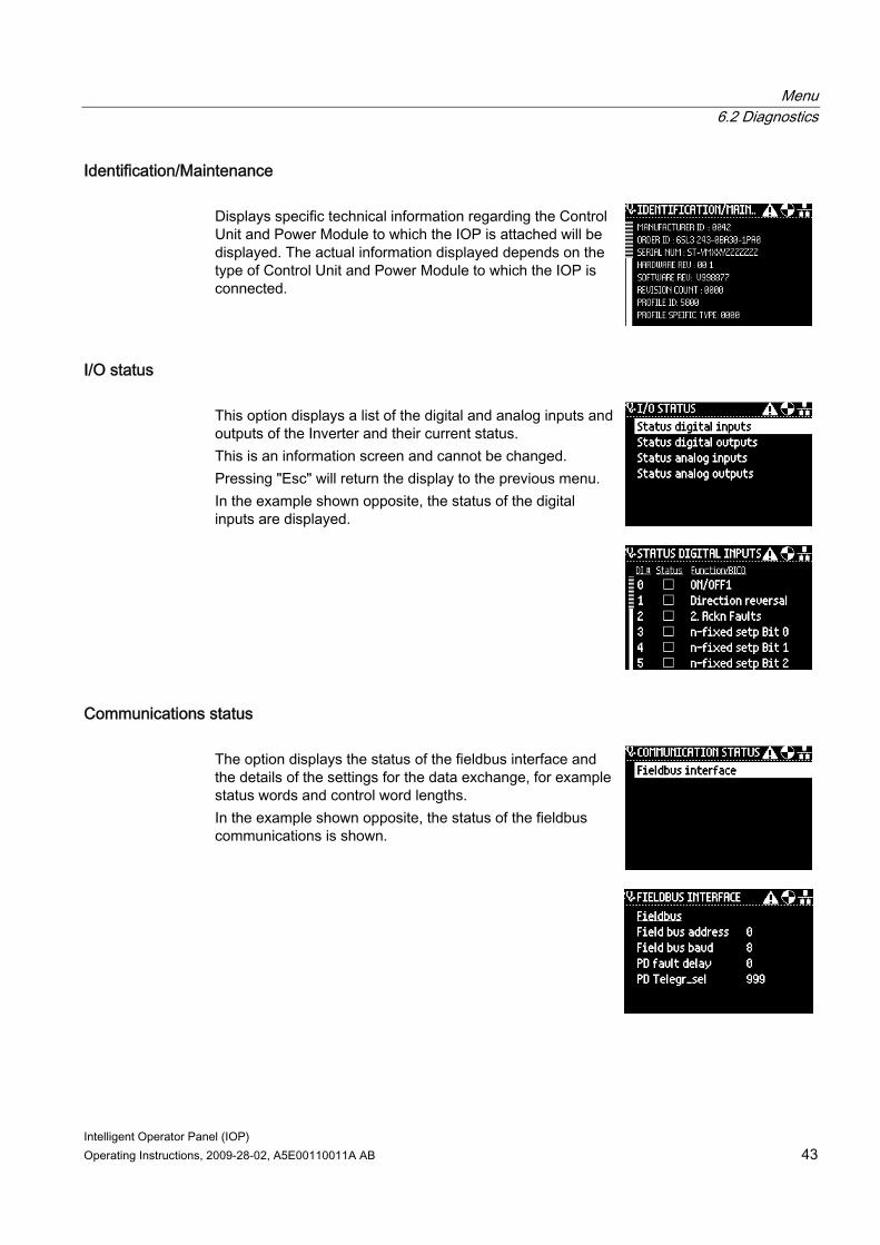
Identification/Maintenance Displays specific technical information regarding the Control Unit and Power Module to which the IOP is attached will be displayed. The actual information displayed depends on the type of Control Unit and Power Module to which the IOP is connected.
I/O status This option displays a list of the digital and analog inputs and outputs of the Inverter and their current status. This is an information screen and cannot be changed. Pressing "Esc" will return the display to the previous menu. In the example shown opposite, the status of the digital inputs are displayed.
Communications status The option displays the status of the fieldbus interface and the details of the settings for the data exchange, for example status words and control word lengths. In the example shown opposite, the status of the fieldbus communications is shown.
Menu 6.2 Diagnostics
Intelligent Operator Panel (IOP) 44 Operating Instructions, 2009-28-02, A5E00110011A AB
I/O simulation
WARNING Loss of control of the Inverter If the Inverter is started using the I/O simulation and the IOP is removed from the Inverter it will not be possible to stop the Inverter running the motor. If the I/O simulation is activated, then only the I/O simulation can be used to stop the Inverter.
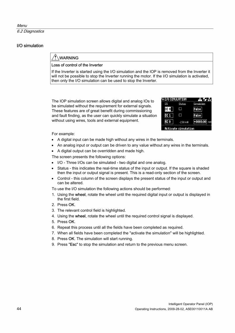
The IOP simulation screen allows digital and analog IOs to be simulated without the requirement for external signals. These features are of great benefit during commissioning and fault finding, as the user can quickly simulate a situation without using wires, tools and external equipment.
For example: • A digital input can be made high without any wires in the terminals. • An analog input or output can be driven to any value without any wires in the terminals. • A digital output can be overridden and made high. The screen presents the following options: • I/O - Three I/Os can be simulated - two digital and one analog. • Status - this indicates the real-time status of the input or output. If the square is shaded
then the input or output signal is present. This is a read-only section of the screen. • Control - this column of the screen displays the present status of the input or output and
can be altered. To use the I/O simulation the following actions should be performed: 1. Using the wheel, rotate the wheel until the required digital input or output is displayed in
the first field. 2. Press OK. 3. The relevant control field is highlighted. 4. Using the wheel, rotate the wheel until the required control signal is displayed. 5. Press OK. 6. Repeat this process until all the fields have been completed as required. 7. When all fields have been completed the "activate the simulation" will be highlighted. 8. Press OK. The simulation will start running. 9. Press "Esc" to stop the simulation and return to the previous menu screen.
Menu 6.3 Parameters
Intelligent Operator Panel (IOP) Operating Instructions, 2009-28-02, A5E00110011A AB 45
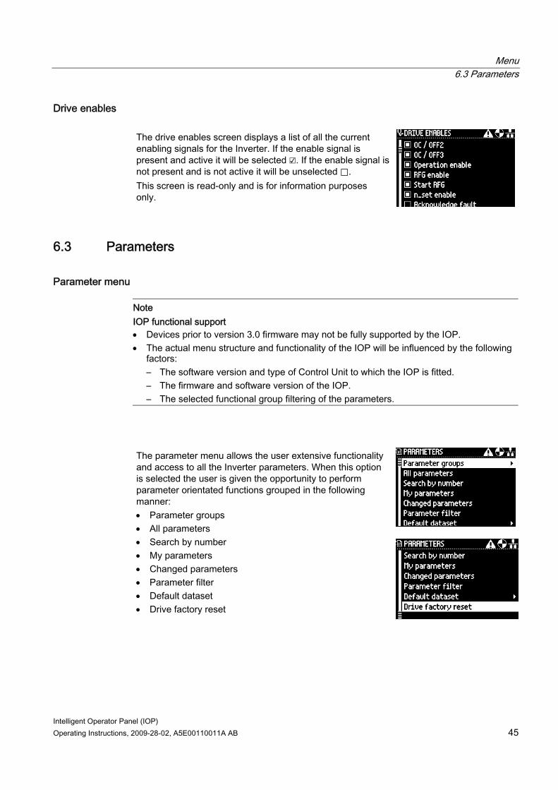
Drive enables The drive enables screen displays a list of all the current enabling signals for the Inverter. If the enable signal is present and active it will be selected ☑. If the enable signal is not present and is not active it will be unselected ⃞. This screen is read-only and is for information purposes only.
6.3 Parameters
Parameter menu
Note IOP functional support • Devices prior to version 3.0 firmware may not be fully supported by the IOP. • The actual menu structure and functionality of the IOP will be influenced by the following
factors: – The software version and type of Control Unit to which the IOP is fitted. – The firmware and software version of the IOP. – The selected functional group filtering of the parameters.
The parameter menu allows the user extensive functionality and access to all the Inverter parameters. When this option is selected the user is given the opportunity to perform parameter orientated functions grouped in the following manner: • Parameter groups • All parameters • Search by number • My parameters • Changed parameters • Parameter filter • Default dataset • Drive factory reset
Menu 6.3 Parameters
Intelligent Operator Panel (IOP) 46 Operating Instructions, 2009-28-02, A5E00110011A AB
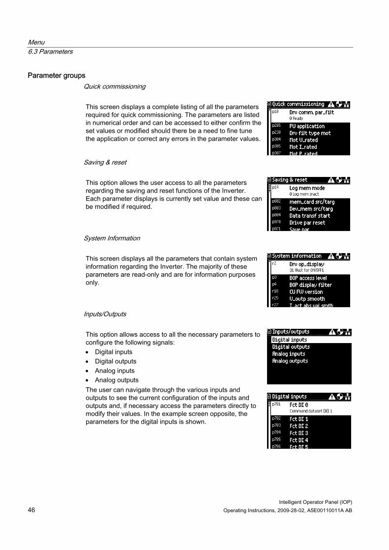
Parameter groups Quick commissioning This screen displays a complete listing of all the parameters required for quick commissioning. The parameters are listed in numerical order and can be accessed to either confirm the set values or modified should there be a need to fine tune the application or correct any errors in the parameter values.
Saving & reset This option allows the user access to all the parameters regarding the saving and reset functions of the Inverter. Each parameter displays is currently set value and these can be modified if required.
System Information This screen displays all the parameters that contain system information regarding the Inverter. The majority of these parameters are read-only and are for information purposes only.
Inputs/Outputs This option allows access to all the necessary parameters to configure the following signals: • Digital inputs • Digital outputs • Analog inputs • Analog outputs The user can navigate through the various inputs and outputs to see the current configuration of the inputs and outputs and, if necessary access the parameters directly to modify their values. In the example screen opposite, the parameters for the digital inputs is shown.
Menu 6.3 Parameters
Intelligent Operator Panel (IOP) Operating Instructions, 2009-28-02, A5E00110011A AB 47
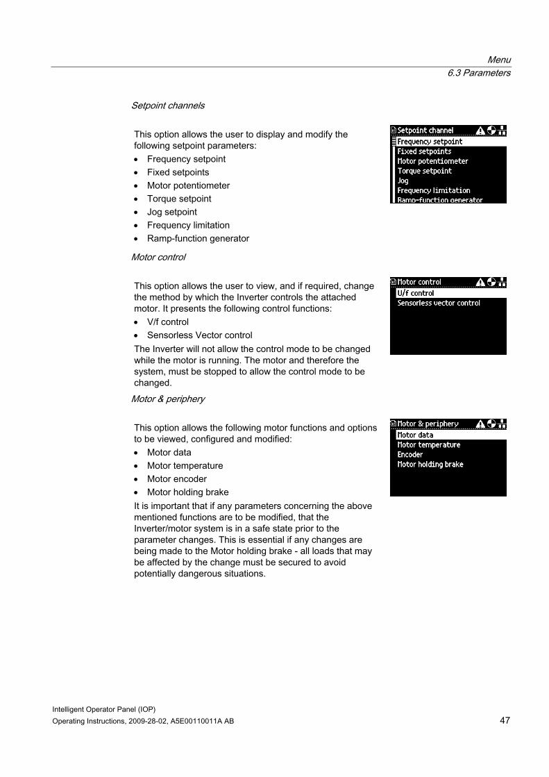
Setpoint channels This option allows the user to display and modify the following setpoint parameters: • Frequency setpoint • Fixed setpoints • Motor potentiometer • Torque setpoint • Jog setpoint • Frequency limitation • Ramp-function generator
Motor control This option allows the user to view, and if required, change the method by which the Inverter controls the attached motor. It presents the following control functions: • V/f control • Sensorless Vector control The Inverter will not allow the control mode to be changed while the motor is running. The motor and therefore the system, must be stopped to allow the control mode to be changed.
Motor & periphery This option allows the following motor functions and options to be viewed, configured and modified: • Motor data • Motor temperature • Motor encoder • Motor holding brake It is important that if any parameters concerning the above mentioned functions are to be modified, that the Inverter/motor system is in a safe state prior to the parameter changes. This is essential if any changes are being made to the Motor holding brake - all loads that may be affected by the change must be secured to avoid potentially dangerous situations.
Menu 6.3 Parameters
Intelligent Operator Panel (IOP) 48 Operating Instructions, 2009-28-02, A5E00110011A AB
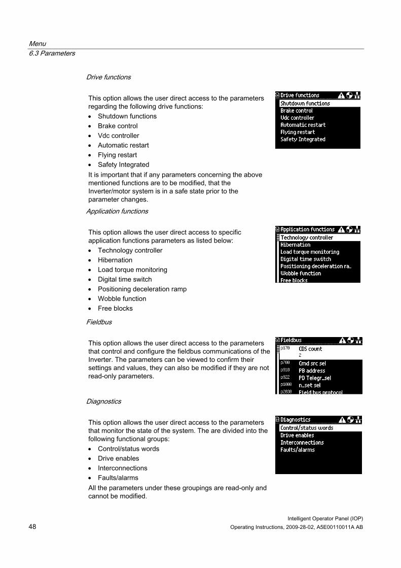
Drive functions This option allows the user direct access to the parameters regarding the following drive functions: • Shutdown functions • Brake control • Vdc controller • Automatic restart • Flying restart • Safety Integrated It is important that if any parameters concerning the above mentioned functions are to be modified, that the Inverter/motor system is in a safe state prior to the parameter changes.
Application functions This option allows the user direct access to specific application functions parameters as listed below: • Technology controller • Hibernation • Load torque monitoring • Digital time switch • Positioning deceleration ramp • Wobble function • Free blocks
Fieldbus This option allows the user direct access to the parameters that control and configure the fieldbus communications of the Inverter. The parameters can be viewed to confirm their settings and values, they can also be modified if they are not read-only parameters.
Diagnostics This option allows the user direct access to the parameters that monitor the state of the system. The are divided into the following functional groups: • Control/status words • Drive enables • Interconnections • Faults/alarms All the parameters under these groupings are read-only and cannot be modified.
Menu 6.3 Parameters
Intelligent Operator Panel (IOP) Operating Instructions, 2009-28-02, A5E00110011A AB 49
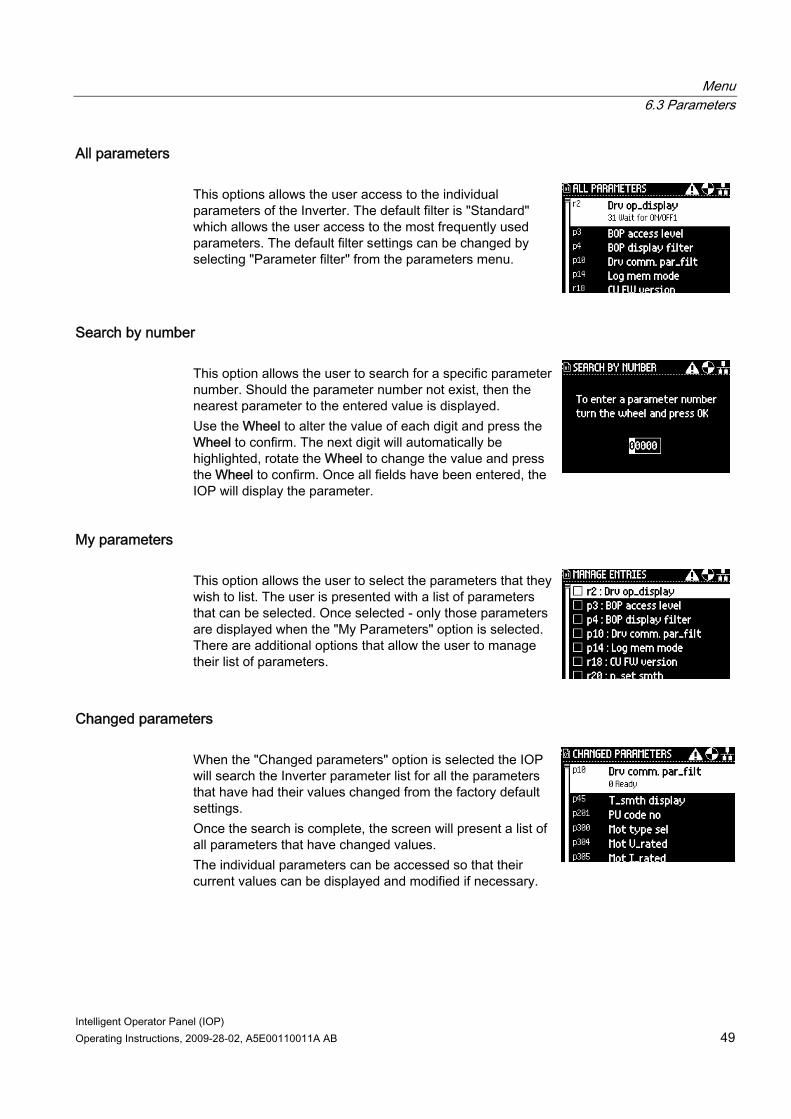
All parameters This options allows the user access to the individual parameters of the Inverter. The default filter is "Standard" which allows the user access to the most frequently used parameters. The default filter settings can be changed by selecting "Parameter filter" from the parameters menu.
Search by number This option allows the user to search for a specific parameter number. Should the parameter number not exist, then the nearest parameter to the entered value is displayed. Use the Wheel to alter the value of each digit and press the Wheel to confirm. The next digit will automatically be highlighted, rotate the Wheel to change the value and press the Wheel to confirm. Once all fields have been entered, the IOP will display the parameter.
My parameters This option allows the user to select the parameters that they wish to list. The user is presented with a list of parameters that can be selected. Once selected - only those parameters are displayed when the "My Parameters" option is selected. There are additional options that allow the user to manage their list of parameters.
Changed parameters When the "Changed parameters" option is selected the IOP will search the Inverter parameter list for all the parameters that have had their values changed from the factory default settings. Once the search is complete, the screen will present a list of all parameters that have changed values. The individual parameters can be accessed so that their current values can be displayed and modified if necessary.
Menu 6.4 Up/Download
Intelligent Operator Panel (IOP) 50 Operating Instructions, 2009-28-02, A5E00110011A AB
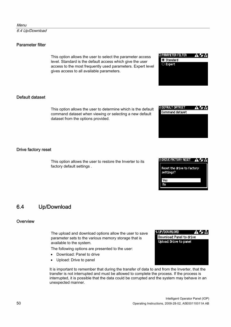
Parameter filter This option allows the user to select the parameter access level. Standard is the default access which give the user access to the most frequently used parameters. Expert level gives access to all available parameters.
Default dataset This option allows the user to determine which is the default command dataset when viewing or selecting a new default dataset from the options provided.
Drive factory reset This option allows the user to restore the Inverter to its factory default settings .
6.4 Up/Download
Overview The upload and download options allow the user to save parameter sets to the various memory storage that is available to the system. The following options are presented to the user: • Download: Panel to drive • Upload: Drive to panel
It is important to remember that during the transfer of data to and from the Inverter, that the transfer is not interrupted and must be allowed to complete the process. If the process is interrupted, it is possible that the data could be corrupted and the system may behave in an unexpected manner.
Menu 6.5 Extras
Intelligent Operator Panel (IOP) Operating Instructions, 2009-28-02, A5E00110011A AB 51
6.5 Extras
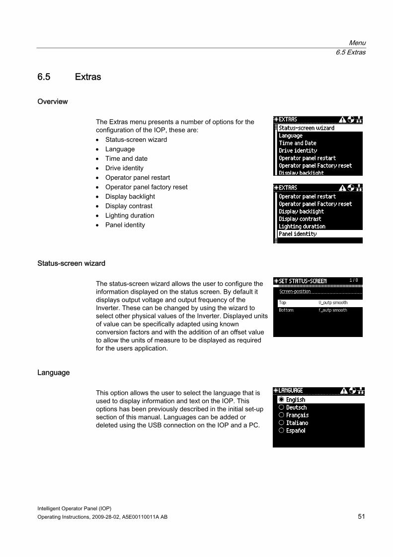
Overview The Extras menu presents a number of options for the configuration of the IOP, these are: • Status-screen wizard • Language • Time and date • Drive identity • Operator panel restart • Operator panel factory reset • Display backlight • Display contrast • Lighting duration • Panel identity
Status-screen wizard The status-screen wizard allows the user to configure the information displayed on the status screen. By default it displays output voltage and output frequency of the Inverter. These can be changed by using the wizard to select other physical values of the Inverter. Displayed units of value can be specifically adapted using known conversion factors and with the addition of an offset value to allow the units of measure to be displayed as required for the users application.
Language This option allows the user to select the language that is used to display information and text on the IOP. This options has been previously described in the initial set-up section of this manual. Languages can be added or deleted using the USB connection on the IOP and a PC.
Menu 6.5 Extras
Intelligent Operator Panel (IOP) 52 Operating Instructions, 2009-28-02, A5E00110011A AB
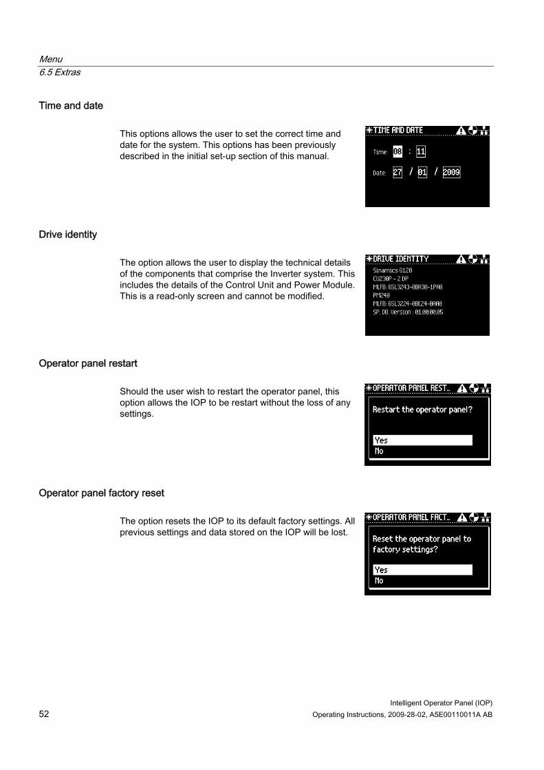
Time and date This options allows the user to set the correct time and date for the system. This options has been previously described in the initial set-up section of this manual.
Drive identity The option allows the user to display the technical details of the components that comprise the Inverter system. This includes the details of the Control Unit and Power Module. This is a read-only screen and cannot be modified.
Operator panel restart Should the user wish to restart the operator panel, this option allows the IOP to be restart without the loss of any settings.
Operator panel factory reset The option resets the IOP to its default factory settings. All previous settings and data stored on the IOP will be lost.
Menu 6.5 Extras
Intelligent Operator Panel (IOP) Operating Instructions, 2009-28-02, A5E00110011A AB 53
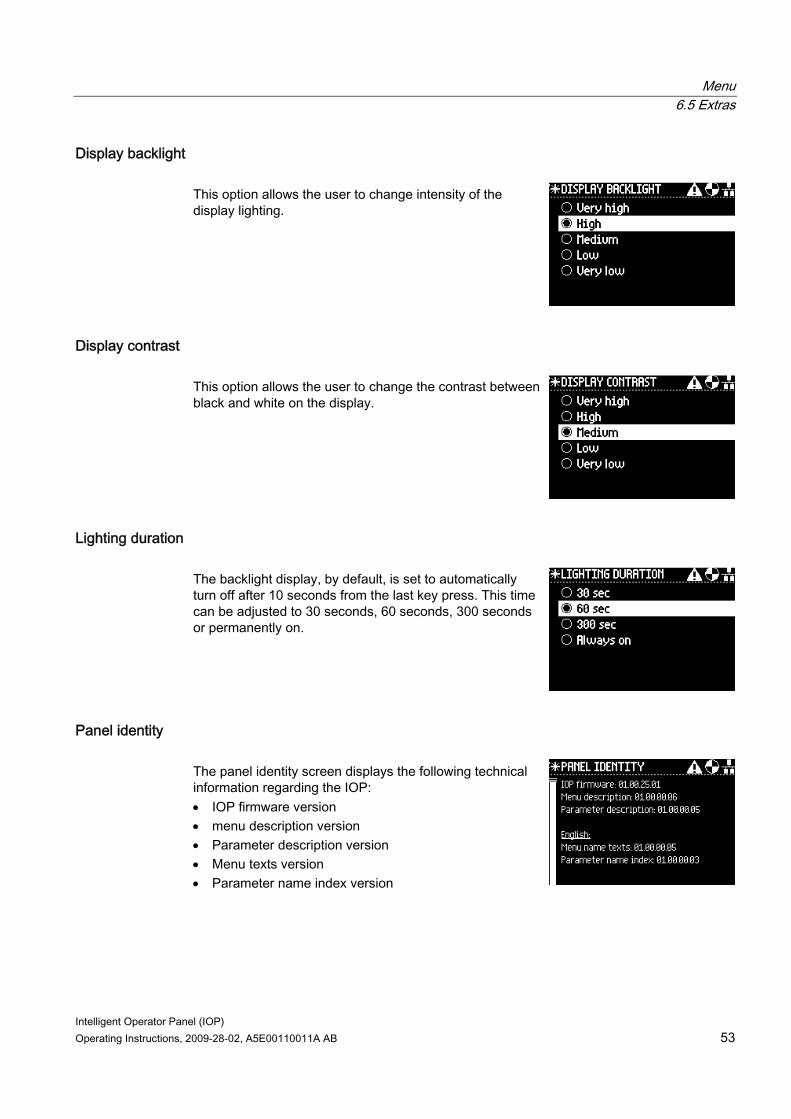
Display backlight This option allows the user to change intensity of the display lighting.
Display contrast This option allows the user to change the contrast between black and white on the display.
Lighting duration The backlight display, by default, is set to automatically turn off after 10 seconds from the last key press. This time can be adjusted to 30 seconds, 60 seconds, 300 seconds or permanently on.
Panel identity The panel identity screen displays the following technical information regarding the IOP: • IOP firmware version • menu description version • Parameter description version • Menu texts version • Parameter name index version

Intelligent Operator Panel (IOP) Operating Instructions, 2009-28-02, A5E00110011A AB 55
Options 77.1 Door mounting kit
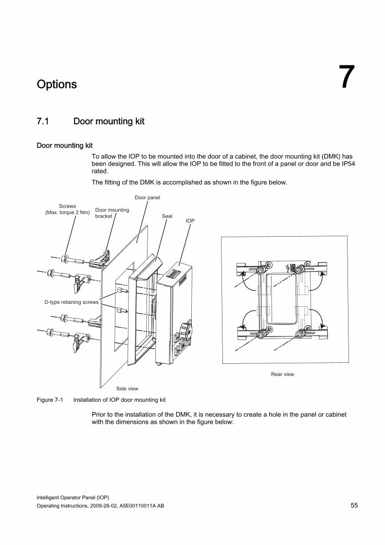
Door mounting kit To allow the IOP to be mounted into the door of a cabinet, the door mounting kit (DMK) has been designed. This will allow the IOP to be fitted to the front of a panel or door and be IP54 rated. The fitting of the DMK is accomplished as shown in the figure below.
Figure 7-1 Installation of IOP door mounting kit
Prior to the installation of the DMK, it is necessary to create a hole in the panel or cabinet with the dimensions as shown in the figure below:
Options 7.1 Door mounting kit
Intelligent Operator Panel (IOP) 56 Operating Instructions, 2009-28-02, A5E00110011A AB
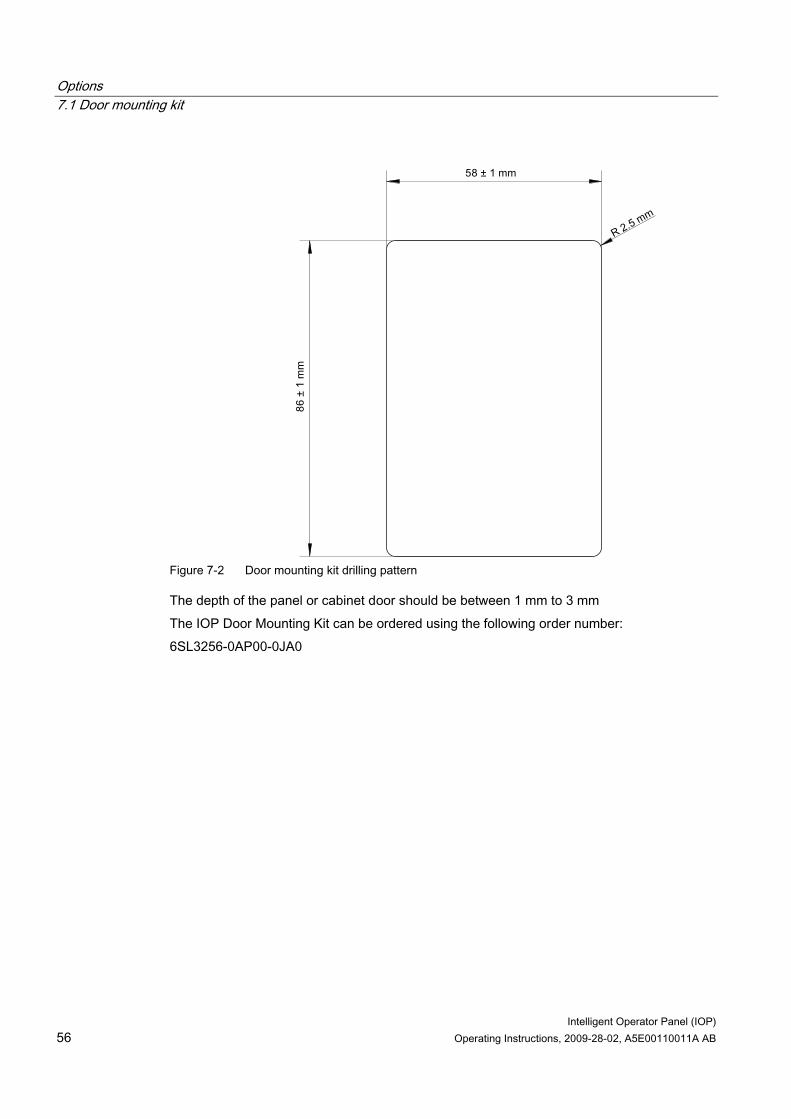
Figure 7-2 Door mounting kit drilling pattern
The depth of the panel or cabinet door should be between 1 mm to 3 mm The IOP Door Mounting Kit can be ordered using the following order number: 6SL3256-0AP00-0JA0
Options 7.2 Hand-held device
Intelligent Operator Panel (IOP) Operating Instructions, 2009-28-02, A5E00110011A AB 57
7.2 Hand-held device
hand-held device
WARNING Charging unit • The charging unit for the rechargeable batteries is contained within the hand-held device
for the sole purpose of charging rechargeable batteries. • The charging unit contained within the hand-held device should not be used with
standard "AA" batteries as this will result in damage to the batteries and the hand-held device.
• Only the supplied power supply unit should be used with the IOP. The use of any other power supply units could seriously damage the hand-held kit.
Note Battery lifetime With the supplied rechargeable batteries in a fully-charged state they should last for approximately 10 hours; the use of normal "AA" batteries may last considerably less time. Industrial environment The IOP has been designed for use within a Class A Industrial environment only. Disposal of batteries The batteries supplied with the IOP must be disposed of in accordance with local and national environmental policies. Battery status The battery status is displayed at the top right-hand corner of the IOP display. Battery charging If the batteries are put on charge and the batteries are fully discharged; the charging unit will enter a 'pre-charge' state. During the pre-charge state the LED will not be lit, therefore there may be a delay before the charging LED lights up.
The IOP has no internal power source, so to increase the IOP's versatility, the hand-held device has been designed.
Table 7- 1 Hand-held device order information
Order number Item quantity Item Remarks 1 IOP 1 Hand-held module 1 Power supply unit 4 Rechargeable batteries 1.2 V NiMH
6SL3255-0AA00-4HA0
1 RS232 cable
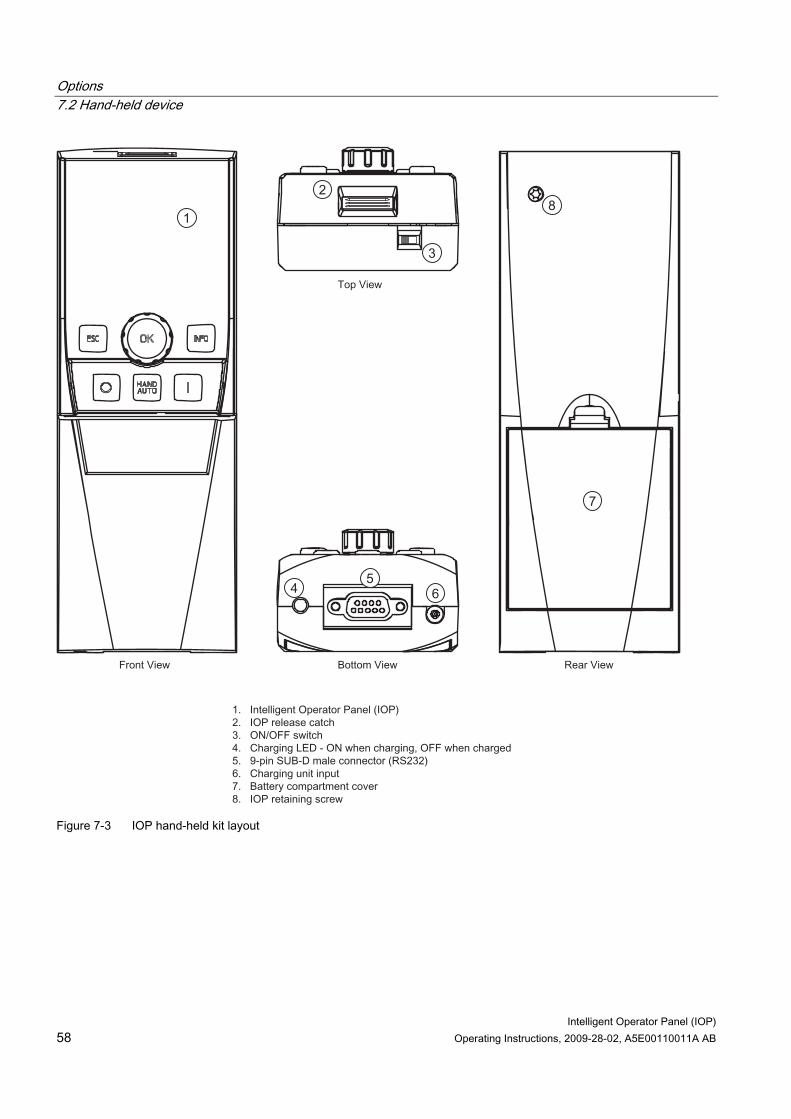
The layout of the IOP hand-held device is shown in the figure below.
Options 7.2 Hand-held device
Intelligent Operator Panel (IOP) 58 Operating Instructions, 2009-28-02, A5E00110011A AB
Figure 7-3 IOP hand-held kit layout
Options 7.2 Hand-held device
Intelligent Operator Panel (IOP) Operating Instructions, 2009-28-02, A5E00110011A AB 59
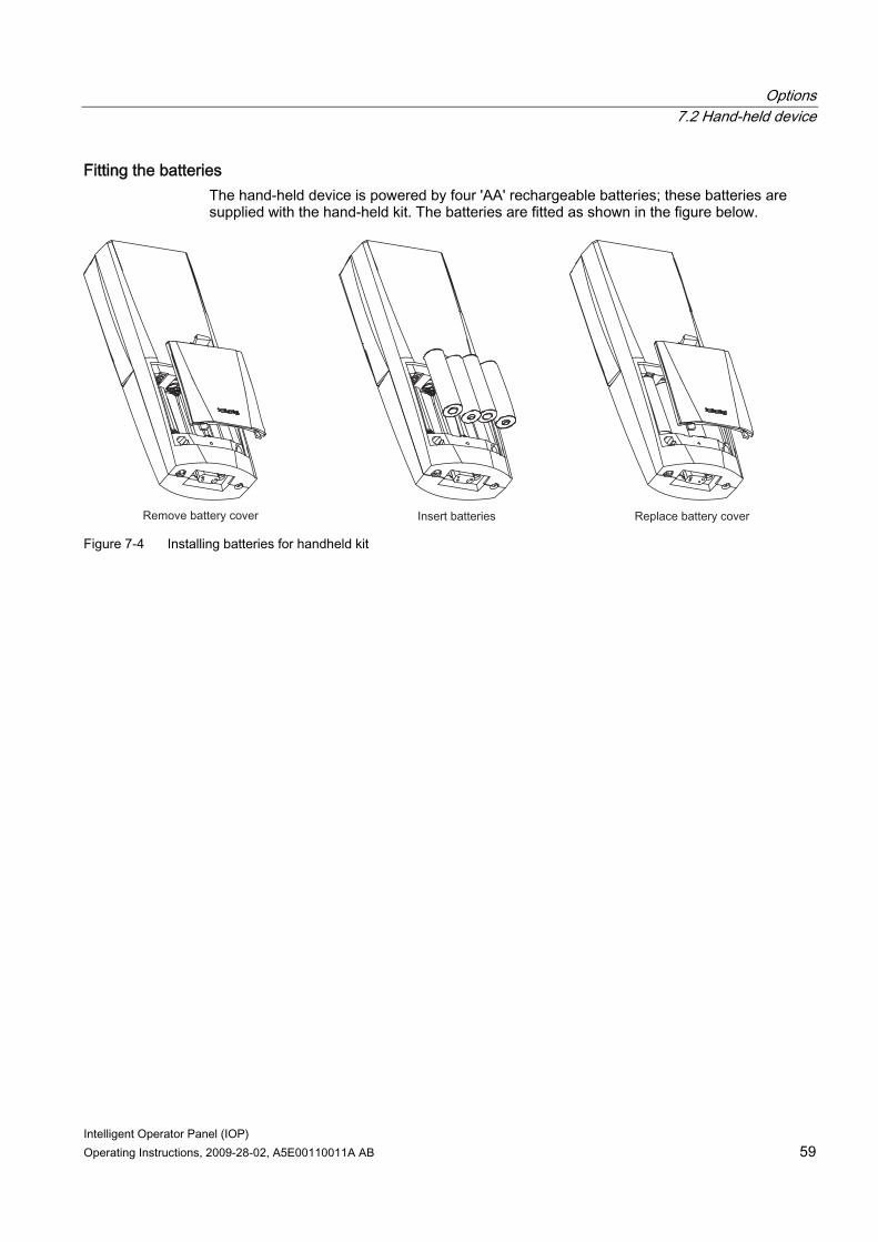
Fitting the batteries The hand-held device is powered by four 'AA' rechargeable batteries; these batteries are supplied with the hand-held kit. The batteries are fitted as shown in the figure below.
Figure 7-4 Installing batteries for handheld kit

Intelligent Operator Panel (IOP) Operating Instructions, 2009-28-02, A5E00110011A AB 61
Technical data 88.1 Technical specifications
IOP technical data
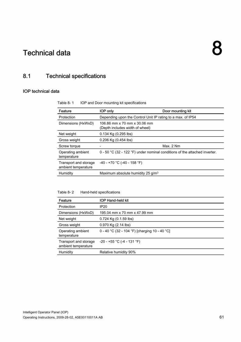
Table 8- 1 IOP and Door mounting kit specifications
Feature IOP only Door mounting kit Protection Depending upon the Control Unit IP rating to a max. of IP54 Dimensions (HxWxD) 106.86 mm x 70 mm x 30.06 mm
(Depth includes width of wheel)
Net weight 0.134 Kg (0.295 lbs) Gross weight 0.206 Kg (0.454 lbs) Screw torque - Max. 2 Nm Operating ambient temperature
0 - 50 °C (32 - 122 °F) under nominal conditions of the attached inverter.
Transport and storage ambient temperature
-40 - +70 °C (-40 - 158 °F)
Humidity Maximum absolute humidity 25 g/m3
Table 8- 2 Hand-held specifications
Feature IOP Hand-held kit Protection IP20 Dimensions (HxWxD) 195.04 mm x 70 mm x 47.99 mm Net weight 0.724 Kg (0.1.59 lbs) Gross weight 0.970 Kg (2.14 lbs) Operating ambient temperature
0 - 40 °C (32 - 104 °F) [charging 10 - 40 °C]
Transport and storage ambient temperature
-20 - +55 °C (-4 - 131 °F)
Humidity Relative humidity 90%

www.siemens.com/automation
Änderungen vorbehaltenE86060-KXXXX-AXXX-AX(-XXXX)© Siemens AG 2009
Siemens AGIndustry SectorPostfach 48 4890026 NÜRNBERGDEUTSCHLAND


![EN 13445-3 11.5.5a - MET-Calc - homemet-calc.com/soubory/Content/Narrow face flange - smooth... · 2020. 4. 26. · } o u ] o r Ç ] o v P Z WZS VFUHZ ò ð ì D } o u ] o r v P Z](https://img.pdfslide.net/doc/110x75/6115d21e24f2f0414d765fe8/en-13445-3-1155a-met-calc-homemet-calccomsouborycontentnarrow-face-flange.jpg)

![(U]VÒEHW - bkk.hu · 'hÀn )huhqf wÒul hydqjÒolnxv whpsorp /xwkhudq fkxufk ulÀvnhuÒn)huulv zkhho)ùogdodwwl 9dv wl 0 ]hxp 0loohqqlxp 8qghujurxqg 0xvhxp %hoyÀurv /lsöwyÀurv](https://img.pdfslide.net/doc/110x75/5c6ee86109d3f29a798b94d7/uvoehw-bkkhu-han-huhqf-woul-hydqjoolnxv-whpsorp-xwkhudq-fkxufk-ulavnhuonhuulv.jpg)


![ACCESSORI A MURARE - CPA Piscine · 6nlpphu d erffd vwdqgdug suroxqjd surirqglwj pp uli 6/ 0 ... dwr shu lqlh] lrqh gl ... 9dfxxp srlqw zlwk wkurjkzdoo pp iru olqhu dqg vfuhz fds](https://img.pdfslide.net/doc/110x75/5b3c25857f8b9a1a678f6726/accessori-a-murare-cpa-6nlpphu-d-erffd-vwdqgdug-suroxqjd-surirqglwj-pp-uli.jpg)
![971 Common Specifications HT TVM with DLMS 844...VWDELOL]HG YLUJLQ 3RO\FDUERQDWH FDVLQJ RI SURMHFWLRQ PRXQWLQJ W\SH 7KH PHWHU FRYHU VKRXOG EH WUDQVSDUHQW IRU HDV\ UHDGLQJ RI GLVSOD\HG](https://img.pdfslide.net/doc/110x75/5fce8e8dd6bb8e4c6d14d239/971-common-specifications-ht-tvm-with-dlms-vwdelolhg-ylujlq-3rofduerqdwh-fdvlqj.jpg)


![bss bsc bssc manual - enertik.com.ar · ^ } o Ç ^ o ] } v 8vh wkh iroorzlqj judsklfv wr khos ghwhuplqh \rxu rswlpdo prxqwlqj dqjoh ,i \rx duh orfdwhg lq wkh](https://img.pdfslide.net/doc/110x75/5c8c105e09d3f218758c611b/bss-bsc-bssc-manual-o-c-o-v-8vh-wkh-iroorzlqj-judsklfv-wr-khos.jpg)