Embed Size (px)
Citation preview
SINBAD
Ralph W. Aßmann Leading Scientist, DESY
LAOLA Collaboration Meeting, Wismar
28.05.2013
Ralph Aßmann | DESY MAC | 07.05.2013 | Page 2
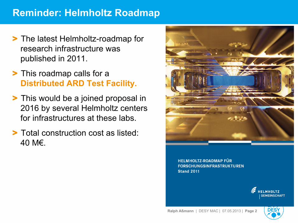
Reminder: Helmholtz Roadmap
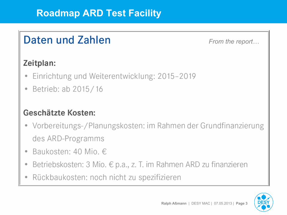
> The latest Helmholtz-roadmap for research infrastructure was published in 2011.
> This roadmap calls for a Distributed ARD Test Facility.
> This would be a joined proposal in 2016 by several Helmholtz centers for infrastructures at these labs.
> Total construction cost as listed: 40 M€.
Ralph Aßmann | DESY MAC | 07.05.2013 | Page 3
Roadmap ARD Test Facility
From the report…
Ralph Aßmann | DESY MAC | 07.05.2013 | Page 4
Why a Distributed ARD Test Facility?
> German accelerator tradition is very strong and in several aspects world-leading à join up forces in ARD, as together we are stronger!
> Avoid duplication of critical R&D in Helmholtz centers, institutes and partners.
> Profit from and exchange technical developments in other places (e.g. UHV techniques with plasmas, instrumentation, simulation, …).
> Open up expensive accelerator test facilities for usage by our fellow research partners.
> Words are nice, but how to best achieve this? A common, distributed research infrastructure for accelerator R&D à Distributed ARD test facility. § Work on a common proposal will support technical exchange and build common long-
term strategy.
§ A common distributed facility costs additional budget (additional test stands) and can only be implemented with the funding mentioned in the Helmholtz roadmap.
Ralph Aßmann | DESY MAC | 07.05.2013 | Page 5
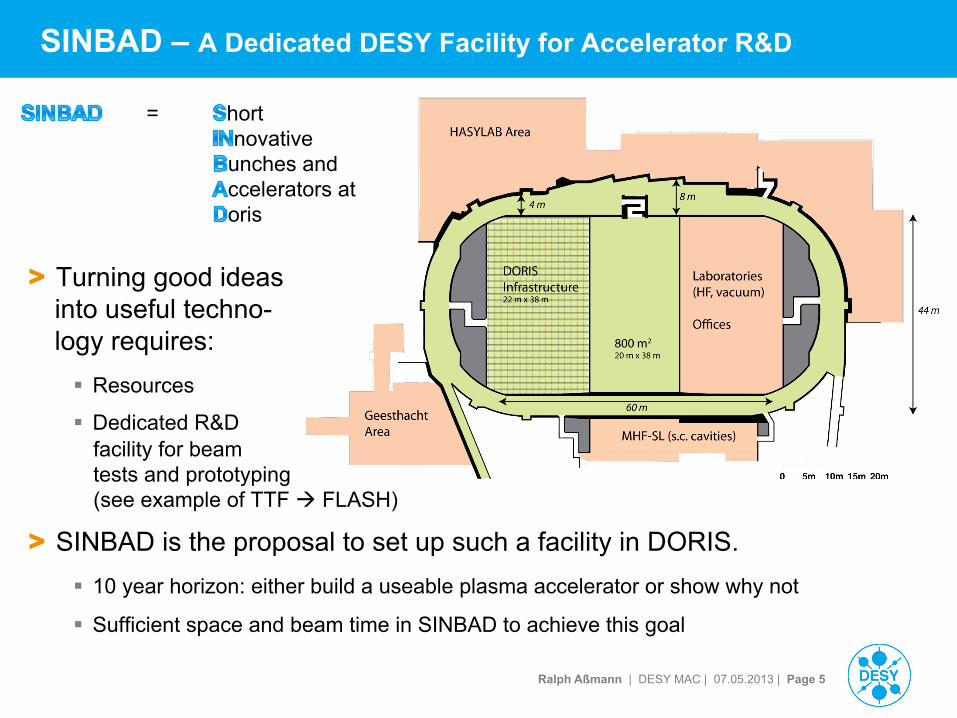
SINBAD – A Dedicated DESY Facility for Accelerator R&D
= hort novative unches and ccelerators at oris
> Turning good ideas into useful techno- logy requires: § Resources
§ Dedicated R&D facility for beam tests and prototyping (see example of TTF à FLASH)
> SINBAD is the proposal to set up such a facility in DORIS. § 10 year horizon: either build a useable plasma accelerator or show why not
§ Sufficient space and beam time in SINBAD to achieve this goal
Ralph Aßmann | DESY MAC | 07.05.2013 | Page 6
DORIS DESY Laser Laboratory
Ralph Aßmann | DESY MAC | 07.05.2013 | Page 7
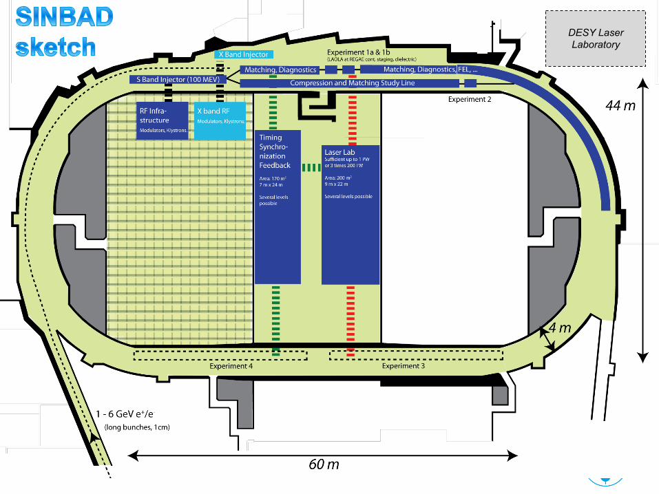
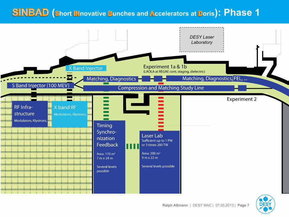
( hort novative unches and ccelerators at oris): Phase 1
DESY Laser Laboratory
Ralph Aßmann | DESY MAC | 07.05.2013 | Page 8
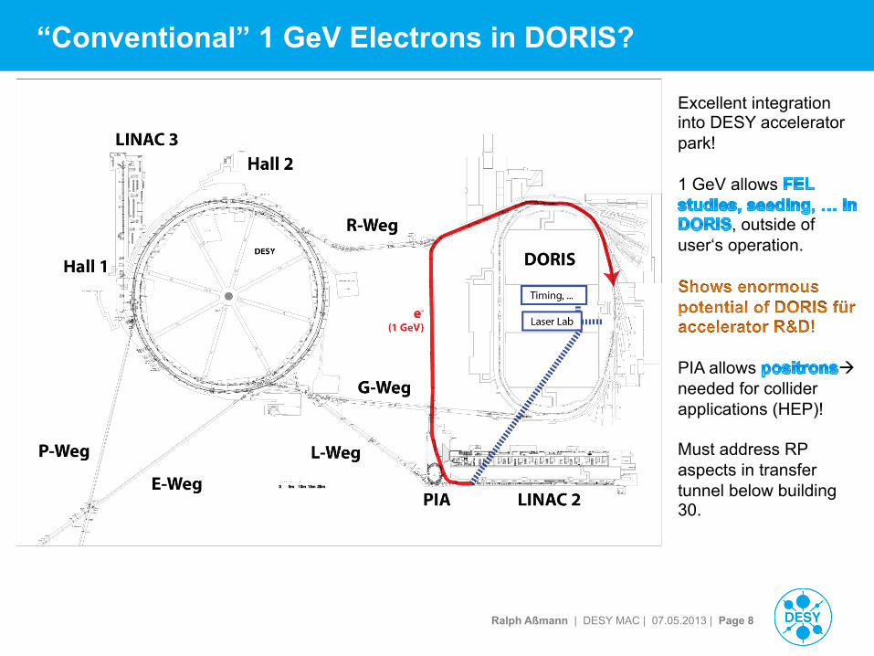
“Conventional” 1 GeV Electrons in DORIS?
Excellent integration into DESY accelerator park! 1 GeV allows
, outside of user‘s operation.
PIA allows à needed for collider applications (HEP)! Must address RP aspects in transfer tunnel below building 30.
Ralph Aßmann | DESY MAC | 07.05.2013 | Page 9
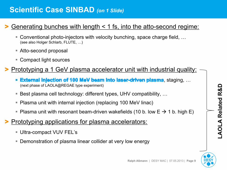
Scientific Case SINBAD (on 1 Slide)
> Generating bunches with length < 1 fs, into the atto-second regime: § Conventional photo-injectors with velocity bunching, space charge field, …
(see also Holger Schlarb, FLUTE, …)
§ Atto-second proposal
§ Compact light sources
> Prototyping a 1 GeV plasma accelerator unit with industrial quality: , staging, …
(next phase of LAOLA@REGAE type experiment)
§ Best plasma cell technology: different types, UHV compatibility, …
§ Plasma unit with internal injection (replacing 100 MeV linac)
§ Plasma unit with resonant beam-driven wakefields (10 b. low E à 1 b. high E)
> Prototyping applications for plasma accelerators: § Ultra-compact VUV FEL’s
§ Demonstration of plasma linear collider at very low energy
LAO
LA R
elat
ed R
&D
LAOLA Collaboration | laola.desy.de | DESY & University Hamburg | April 18, 2013 | Page 00 LAOLA.!
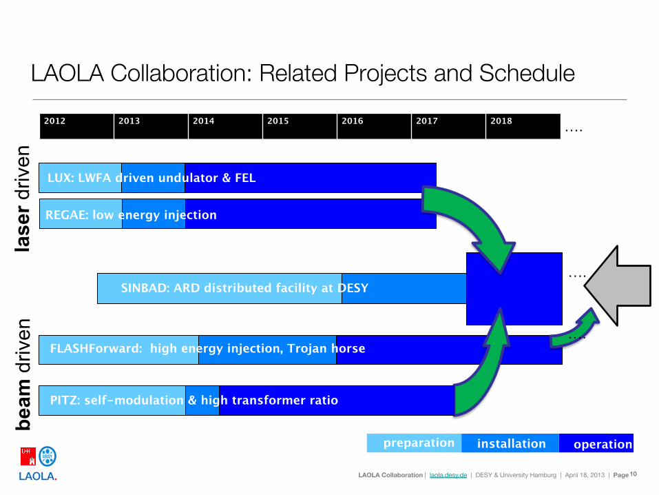
LAOLA Collaboration: Related Projects and Schedule
10
2012 2013 2014 2015 2016 2017 2018
FACET E-210: TROJAN
LUX: LWFA driven undulator & FEL
lase
r driv
en
beam
driv
en
SINBAD: ARD distributed facility at DESY
preparation installation operation
REGAE: low energy injection
PITZ: self-modulation & high transformer ratio
FLASHForward: high energy injection, Trojan horse
….
….
….
Ralph Aßmann | DESY MAC | 07.05.2013 | Page 11
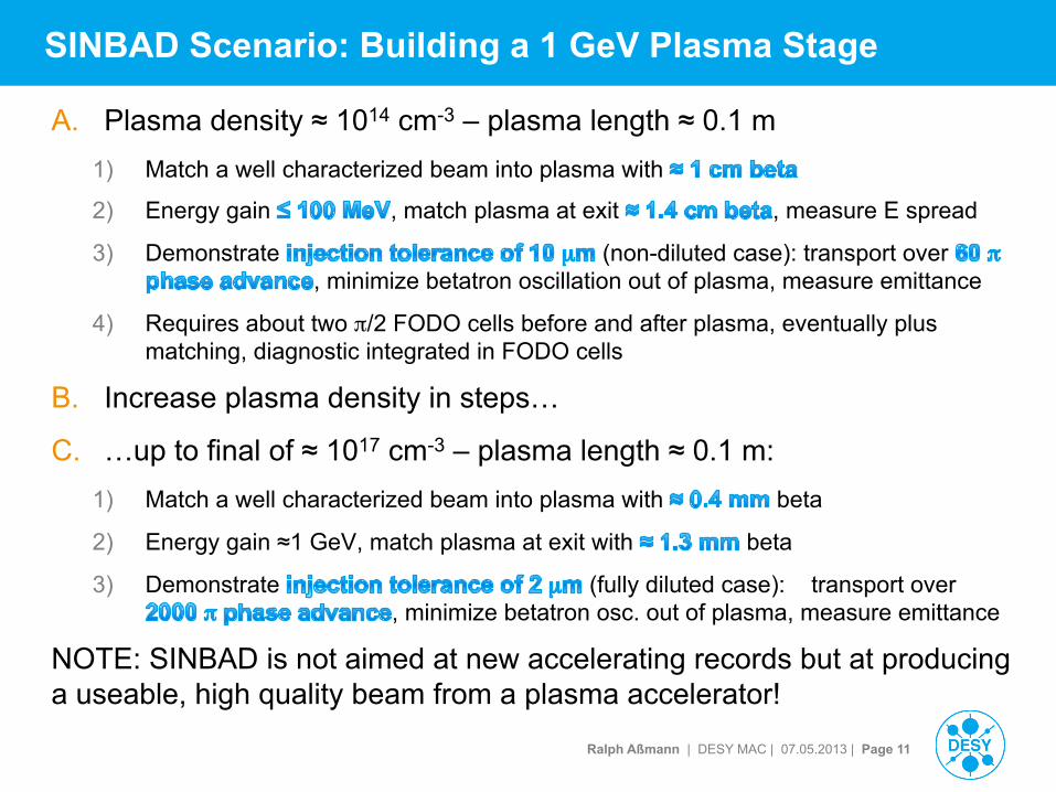
SINBAD Scenario: Building a 1 GeV Plasma Stage
A. Plasma density ≈ 1014 cm-3 – plasma length ≈ 0.1 m 1) Match a well characterized beam into plasma with
2) Energy gain , match plasma at exit , measure E spread
3) Demonstrate (non-diluted case): transport over , minimize betatron oscillation out of plasma, measure emittance
4) Requires about two π/2 FODO cells before and after plasma, eventually plus matching, diagnostic integrated in FODO cells
B. Increase plasma density in steps…
C. …up to final of ≈ 1017 cm-3 – plasma length ≈ 0.1 m: 1) Match a well characterized beam into plasma with beta
2) Energy gain ≈1 GeV, match plasma at exit with beta
3) Demonstrate (fully diluted case): transport over , minimize betatron osc. out of plasma, measure emittance
NOTE: SINBAD is not aimed at new accelerating records but at producing a useable, high quality beam from a plasma accelerator!
Ralph Aßmann | DESY MAC | 07.05.2013 | Page 12
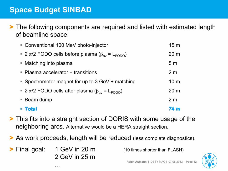
Space Budget SINBAD
> The following components are required and listed with estimated length of beamline space: § Conventional 100 MeV photo-injector 15 m
§ 2 π/2 FODO cells before plasma (βav = LFODO) 20 m
§ Matching into plasma 5 m
§ Plasma accelerator + transitions 2 m
§ Spectrometer magnet for up to 3 GeV + matching 10 m
§ 2 π/2 FODO cells after plasma (βav = LFODO) 20 m
§ Beam dump 2 m
> This fits into a straight section of DORIS with some usage of the neighboring arcs. Alternative would be a HERA straight section.
> As work proceeds, length will be reduced (less complete diagnostics).
> Final goal: 1 GeV in 20 m (10 times shorter than FLASH)
2 GeV in 25 m …
Ralph Aßmann | DESY MAC | 07.05.2013 | Page 13
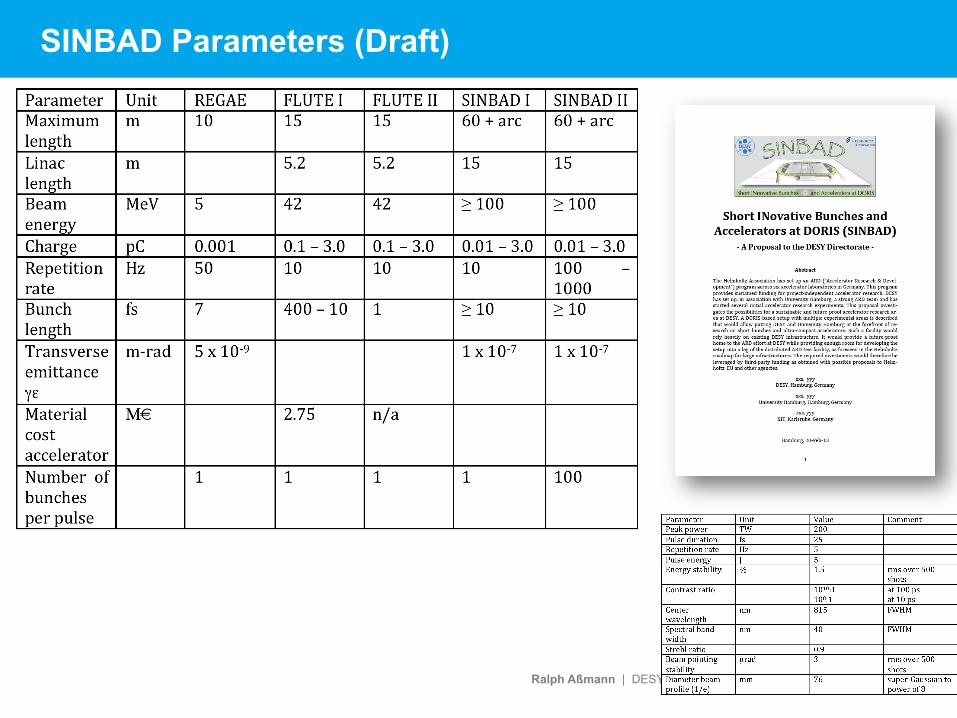
SINBAD Parameters (Draft)
Ralph Aßmann | DESY MAC | 07.05.2013 | Page 14
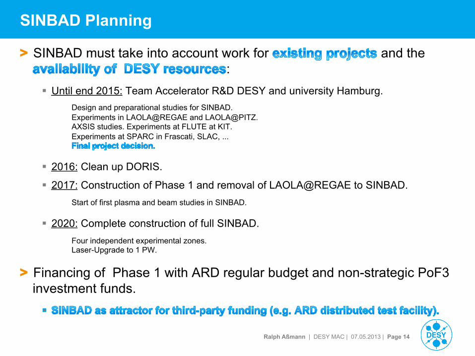
SINBAD Planning
> SINBAD must take into account work for and the :
§ Until end 2015: Team Accelerator R&D DESY and university Hamburg. Design and preparational studies for SINBAD. Experiments in LAOLA@REGAE and LAOLA@PITZ. AXSIS studies. Experiments at FLUTE at KIT. Experiments at SPARC in Frascati, SLAC, ...
§ 2016: Clean up DORIS.
§ 2017: Construction of Phase 1 and removal of LAOLA@REGAE to SINBAD. Start of first plasma and beam studies in SINBAD.
§ 2020: Complete construction of full SINBAD.
Four independent experimental zones. Laser-Upgrade to 1 PW.
> Financing of Phase 1 with ARD regular budget and non-strategic PoF3 investment funds.
Ralph Aßmann | DESY MAC | 07.05.2013 | Page 15
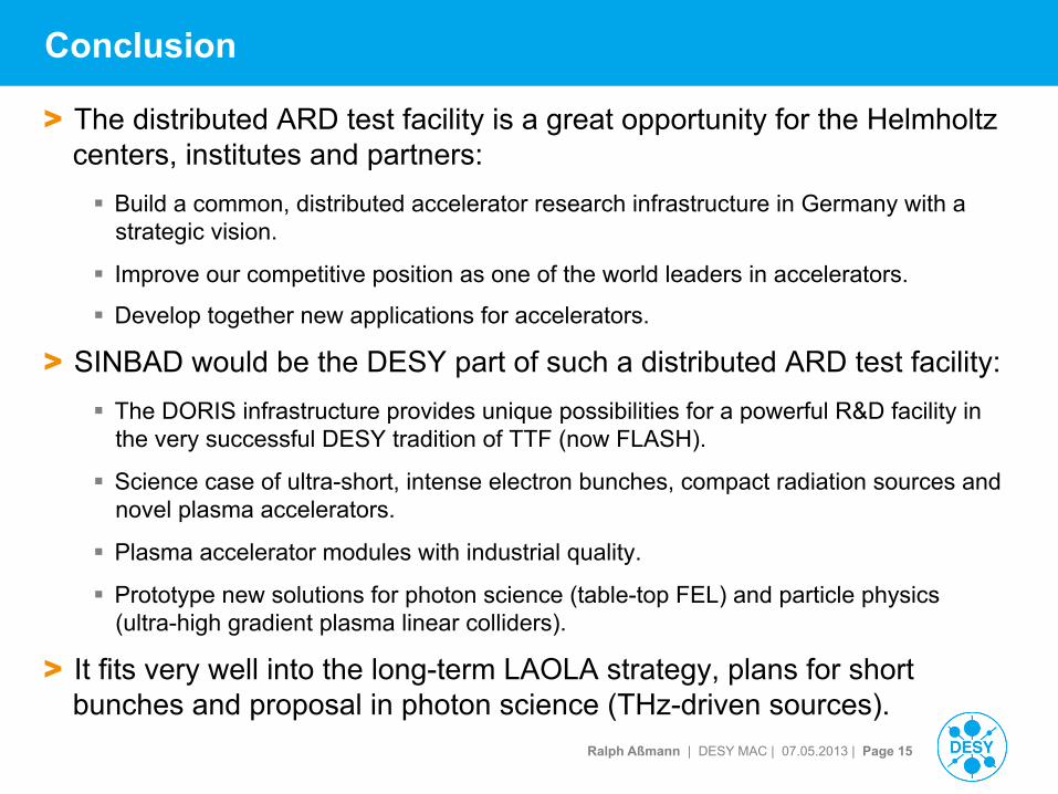
Conclusion
> The distributed ARD test facility is a great opportunity for the Helmholtz centers, institutes and partners: § Build a common, distributed accelerator research infrastructure in Germany with a
strategic vision.
§ Improve our competitive position as one of the world leaders in accelerators.
§ Develop together new applications for accelerators.
> SINBAD would be the DESY part of such a distributed ARD test facility: § The DORIS infrastructure provides unique possibilities for a powerful R&D facility in
the very successful DESY tradition of TTF (now FLASH).
§ Science case of ultra-short, intense electron bunches, compact radiation sources and novel plasma accelerators.
§ Plasma accelerator modules with industrial quality.
§ Prototype new solutions for photon science (table-top FEL) and particle physics (ultra-high gradient plasma linear colliders).
> It fits very well into the long-term LAOLA strategy, plans for short bunches and proposal in photon science (THz-driven sources).
Ralph Aßmann | DESY MAC | 07.05.2013 | Page 16
Thank you for your attention…
Ralph Aßmann | DESY MAC | 07.05.2013 | Page 17
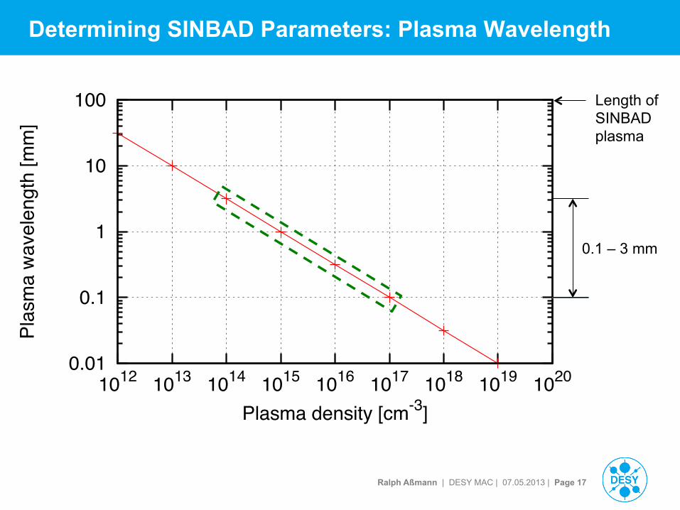
Determining SINBAD Parameters: Plasma Wavelength
0.01
0.1
1
10
100
1012 1013 1014 1015 1016 1017 1018 1019 1020
Plas
ma
wav
elen
gth
[mm
]
Plasma density [cm-3]
Length of SINBAD plasma
0.1 – 3 mm
Ralph Aßmann | DESY MAC | 07.05.2013 | Page 18
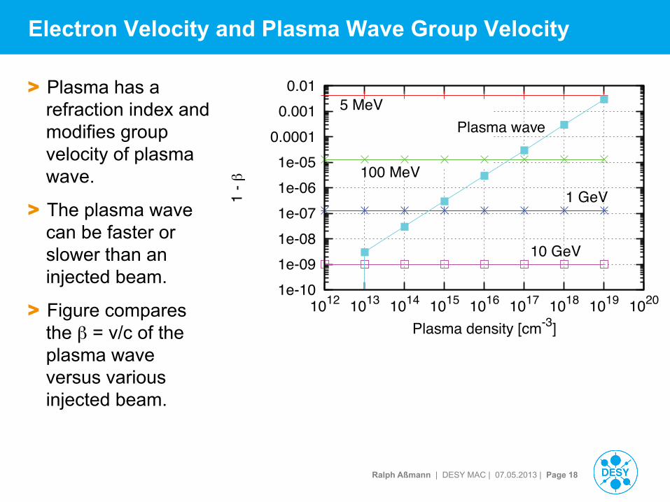
Electron Velocity and Plasma Wave Group Velocity
> Plasma has a refraction index and modifies group velocity of plasma wave.
> The plasma wave can be faster or slower than an injected beam.
> Figure compares the β = v/c of the plasma wave versus various injected beam.
1e-10 1e-09 1e-08 1e-07 1e-06 1e-05
0.0001 0.001 0.01
1012 1013 1014 1015 1016 1017 1018 1019 1020
1 - !
Plasma density [cm-3]
5 MeV
100 MeV1 GeV
10 GeV
Plasma wave
Ralph Aßmann | DESY MAC | 07.05.2013 | Page 19
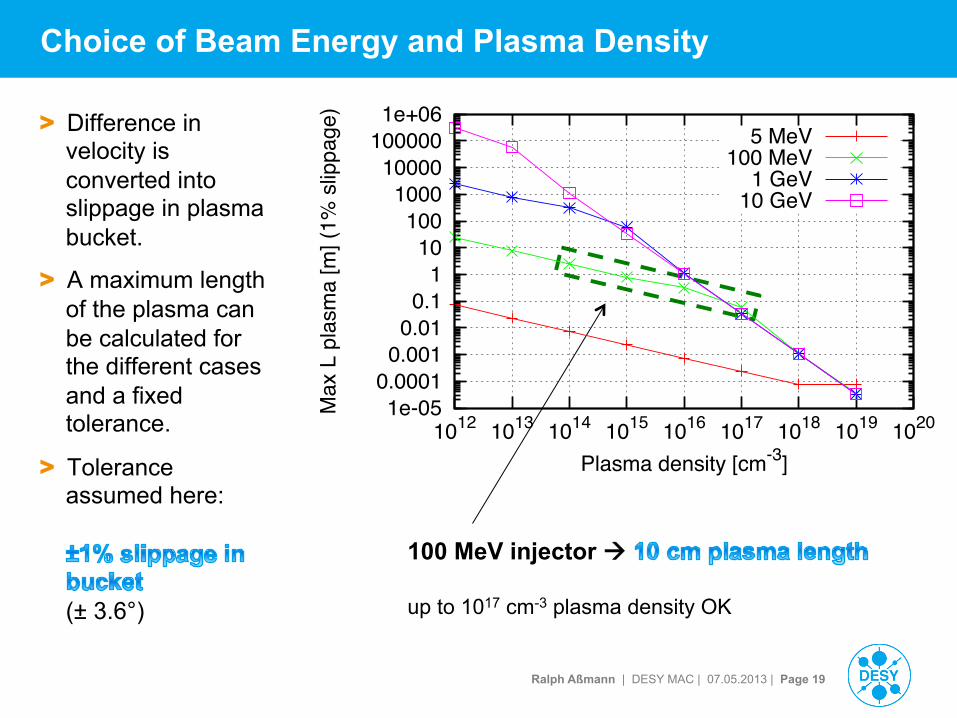
Choice of Beam Energy and Plasma Density
> Difference in velocity is converted into slippage in plasma bucket.
> A maximum length of the plasma can be calculated for the different cases and a fixed tolerance.
> Tolerance assumed here:
(± 3.6°)
100 MeV injector à
up to 1017 cm-3 plasma density OK
1e-05 0.0001
0.001 0.01
0.1 1
10 100
1000 10000
100000 1e+06
1012 1013 1014 1015 1016 1017 1018 1019 1020
Max
L p
lasm
a [m
] (1%
slip
page
)
Plasma density [cm-3]
5 MeV100 MeV
1 GeV10 GeV
Ralph Aßmann | DESY MAC | 07.05.2013 | Page 20
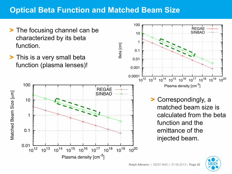
Optical Beta Function and Matched Beam Size
> The focusing channel can be characterized by its beta function.
> This is a very small beta function (plasma lenses)!
0.0001
0.001
0.01
0.1
1
10
100
1012 1013 1014 1015 1016 1017 1018 1019 1020
Beta
[cm
]
Plasma density [cm-3]
REGAESINBAD
0.01
0.1
1
10
100
1012 1013 1014 1015 1016 1017 1018 1019 1020
Mat
ched
Bea
m S
ize
[µm
]
Plasma density [cm-3]
REGAESINBAD
> Correspondingly, a matched beam size is calculated from the beta function and the emittance of the injected beam.
Ralph Aßmann | DESY MAC | 07.05.2013 | Page 21
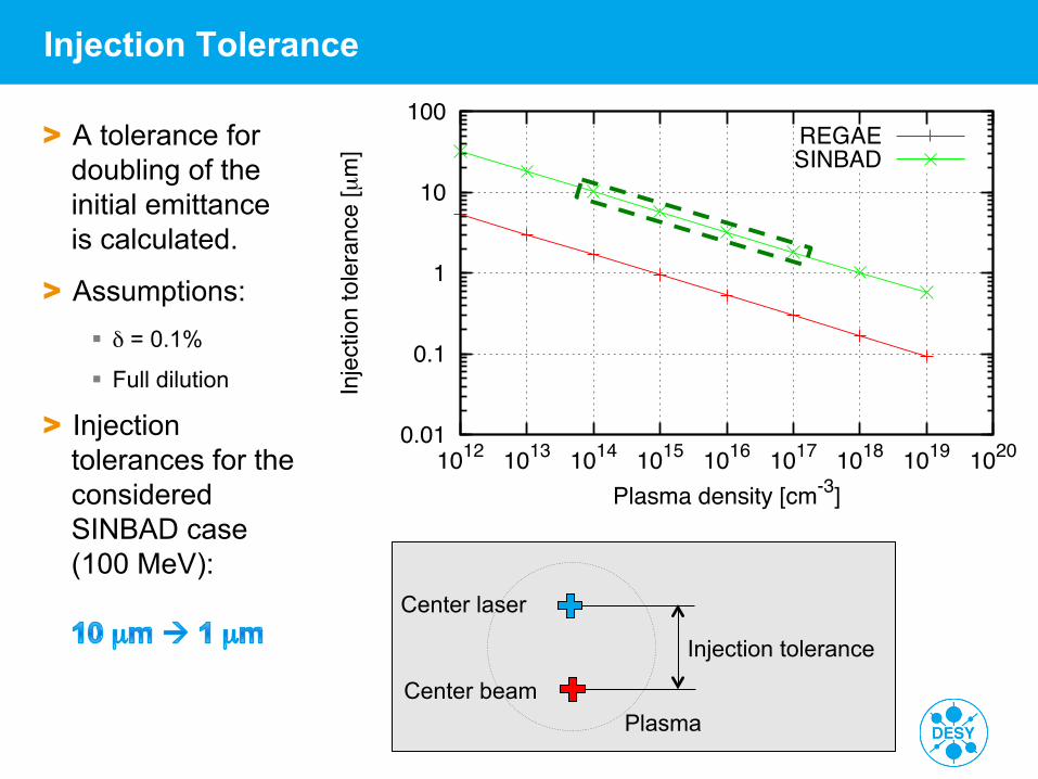
Injection Tolerance
> A tolerance for doubling of the initial emittance is calculated.
> Assumptions: § δ = 0.1%
§ Full dilution
> Injection tolerances for the considered SINBAD case (100 MeV):
0.01
0.1
1
10
100
1012 1013 1014 1015 1016 1017 1018 1019 1020
Inje
ctio
n to
lera
nce
[µm
]
Plasma density [cm-3]
REGAESINBAD
Center laser
Center beam
Injection tolerance
Plasma
Ralph Aßmann | DESY MAC | 07.05.2013 | Page 22
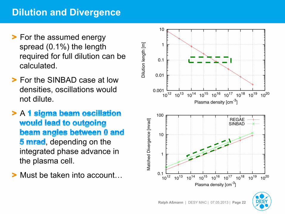
Dilution and Divergence
> For the assumed energy spread (0.1%) the length required for full dilution can be calculated.
> For the SINBAD case at low densities, oscillations would not dilute.
> A
, depending on the integrated phase advance in the plasma cell.
> Must be taken into account… 0.1
1
10
100
1012 1013 1014 1015 1016 1017 1018 1019 1020
Mat
ched
Div
erge
nce
[mra
d]
Plasma density [cm-3]
REGAESINBAD
0.001
0.01
0.1
1
10
1012 1013 1014 1015 1016 1017 1018 1019 1020
Dilu
tion
leng
th [m
]
Plasma density [cm-3]