Embed Size (px)
Citation preview
42
Industrial controllers
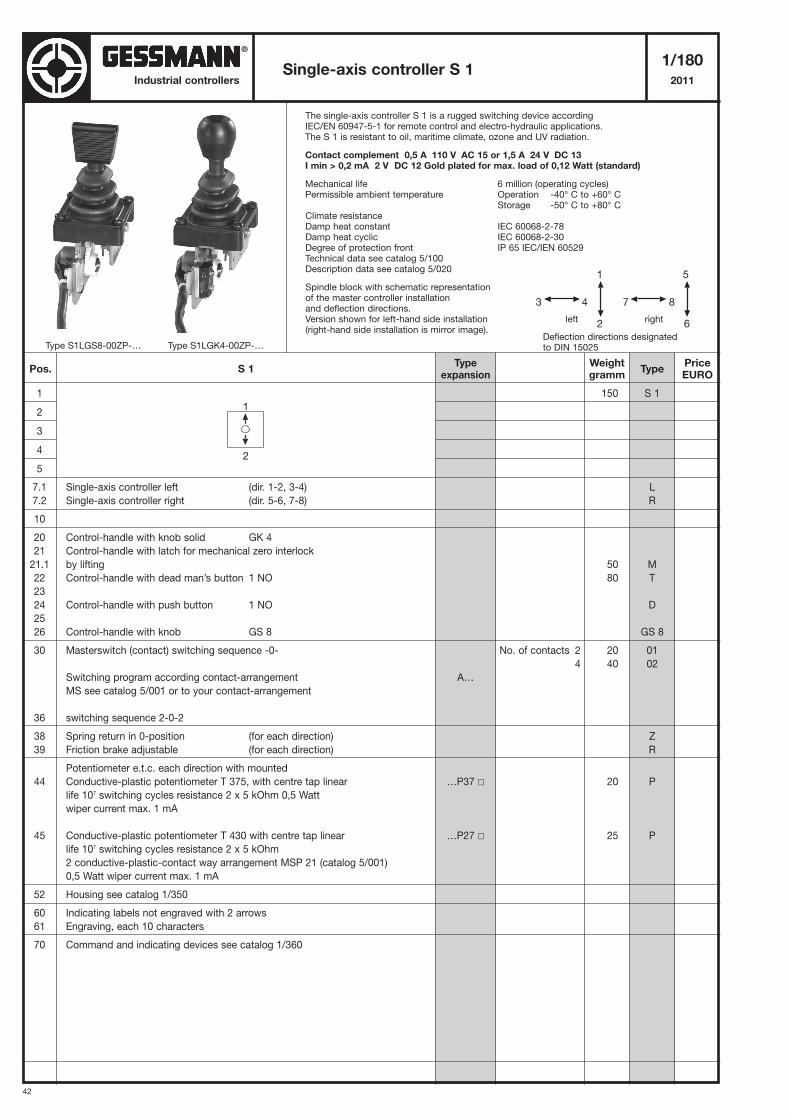
The single-axis controller S 1 is a rugged switching device accordingIEC/EN 60947-5-1 for remote control and electro-hydraulic applications.The S 1 is resistant to oil, maritime climate, ozone and UV radiation.
Contact complement 0,5 A 110 V AC 15 or 1,5 A 24 V DC 13I min > 0,2 mA 2 V DC 12 Gold plated for max. load of 0,12 Watt (standard)
Mechanical life 6 million (operating cycles)Permissible ambient temperature Operation -40° C to +60° C
Storage -50° C to +80° CClimate resistanceDamp heat constant IEC 60068-2-78Damp heat cyclic IEC 60068-2-30Degree of protection front IP 65 IEC/IEN 60529Technical data see catalog 5/100Description data see catalog 5/020
Spindle block with schematic representationof the master controller installationand deflection directions.Version shown for left-hand side installation(right-hand side installation is mirror image).
Single-axis controller S 11/180
2011
1
2
3
4
5
7.1 Single-axis controller left (dir. 1-2, 3-4)
7.2 Single-axis controller right (dir. 5-6, 7-8)
10
20 Control-handle with knob solid GK 4
21 Control-handle with latch for mechanical zero interlock
21.1 by lifting
22 Control-handle with dead man’s button 1 NO
23
24 Control-handle with push button 1 NO
25
26 Control-handle with knob GS 8
30 Masterswitch (contact) switching sequence -0-
Switching program according contact-arrangement
MS see catalog 5/001 or to your contact-arrangement
36 switching sequence 2-0-2
38 Spring return in 0-position (for each direction)
39 Friction brake adjustable (for each direction)
Potentiometer e.t.c. each direction with mounted
44 Conductive-plastic potentiometer T 375, with centre tap linear
life 107 switching cycles resistance 2 x 5 kOhm 0,5 Watt
wiper current max. 1 mA
45 Conductive-plastic potentiometer T 430 with centre tap linear
life 107 switching cycles resistance 2 x 5 kOhm
2 conductive-plastic-contact way arrangement MSP 21 (catalog 5/001)
0,5 Watt wiper current max. 1 mA
52 Housing see catalog 1/350
60 Indicating labels not engraved with 2 arrows
61 Engraving, each 10 characters
70 Command and indicating devices see catalog 1/360
150
50
80
20
40
20
25
S 1
L
R
M
T
D
GS 8
01
02
Z
R
P
P
5
7 8
6
1
3 4
2
Deflection directions designatedto DIN 15025
left right
1
2
Pos. S 1Weightgramm
Typeexpansion
TypePriceEURO
No. of contacts 2
4
A…
…P37 �
…P27 �
Type S1LGS8-00ZP-… Type S1LGK4-00ZP-…
71,-
50,-
38,-
41,-
5,-
43,-
66,-
34,-
27,-
80,-
114,-
9,-
10,-
®
43
Single-axis controller S 11/181
2011Industrial controllers
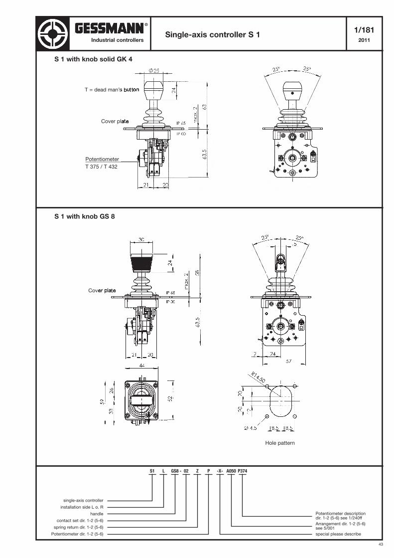
S 1 with knob GS 8
S 1 with knob solid GK 4
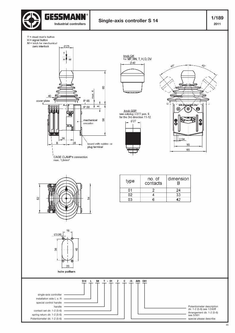
T = dead man’s button
Cover plate
Cover plate
Hole pattern
1
2
Potentiometer
T 375 / T 432
S1 L GS8 - 02 Z P -X- A050 P374
single-axis controller
installation side L o. R
handle
contact set dir. 1-2 (5-6)
spring return dir. 1-2 (5-6)
Potentiometer dir. 1-2 (5-6)
Potentiometer descriptiondir. 1-2 (5-6) see 1/240ff
Arrangement dir. 1-2 (5-6) see 5/001
special please describe
®
44
Industrial controllers
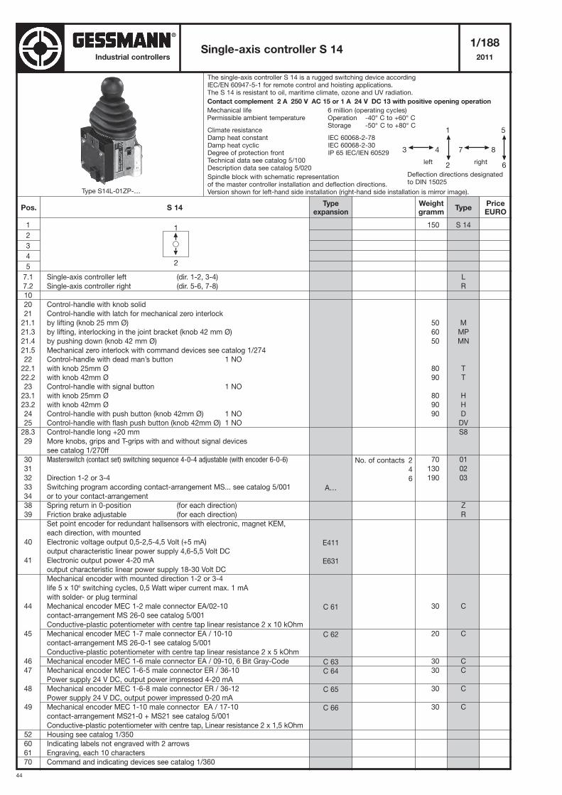
The single-axis controller S 14 is a rugged switching device accordingIEC/EN 60947-5-1 for remote control and hoisting applications.The S 14 is resistant to oil, maritime climate, ozone and UV radiation.
Contact complement 2 A 250 V AC 15 or 1 A 24 V DC 13 with positive opening operation
Mechanical life 6 million (operating cycles)Permissible ambient temperature Operation -40° C to +60° C
Storage -50° C to +80° CClimate resistanceDamp heat constant IEC 60068-2-78Damp heat cyclic IEC 60068-2-30Degree of protection front IP 65 IEC/IEN 60529Technical data see catalog 5/100Description data see catalog 5/020
Spindle block with schematic representationof the master controller installation and deflection directions.Version shown for left-hand side installation (right-hand side installation is mirror image).
Single-axis controller S 141/188
2011
1
2
3
4
5
7.1 Single-axis controller left (dir. 1-2, 3-4)
7.2 Single-axis controller right (dir. 5-6, 7-8)
10
20 Control-handle with knob solid
21 Control-handle with latch for mechanical zero interlock
21.1 by lifting (knob 25 mm Ø)
21.3 by lifting, interlocking in the joint bracket (knob 42 mm Ø)
21.4 by pushing down (knob 42 mm Ø)
21.5 Mechanical zero interlock with command devices see catalog 1/274
22 Control-handle with dead man’s button 1 NO
22.1 with knob 25mm Ø
22.2 with knob 42mm Ø
23 Control-handle with signal button 1 NO
23.1 with knob 25mm Ø
23.2 with knob 42mm Ø
24 Control-handle with push button (knob 42mm Ø) 1 NO
25 Control-handle with flash push button (knob 42mm Ø) 1 NO
28.3 Control-handle long +20 mm
29 More knobs, grips and T-grips with and without signal devices
see catalog 1/270ff
30 Masterswitch (contact set) switching sequence 4-0-4 adjustable (with encoder 6-0-6)
31
32 Direction 1-2 or 3-4
33 Switching program according contact-arrangement MS... see catalog 5/001
34 or to your contact-arrangement
38 Spring return in 0-position (for each direction)
39 Friction brake adjustable (for each direction)
Set point encoder for redundant hallsensors with electronic, magnet KEM,
each direction, with mounted
40 Electronic voltage output 0,5-2,5-4,5 Volt (+5 mA)
output characteristic linear power supply 4,6-5,5 Volt DC
41 Electronic output power 4-20 mA
output characteristic linear power supply 18-30 Volt DC
Mechanical encoder with mounted direction 1-2 or 3-4
life 5 x 10⁶ switching cycles, 0,5 Watt wiper current max. 1 mA
with solder- or plug terminal
44 Mechanical encoder MEC 1-2 male connector EA/02-10
contact-arrangement MS 26-0 see catalog 5/001
Conductive-plastic potentiometer with centre tap linear resistance 2 x 10 kOhm
45 Mechanical encoder MEC 1-7 male connector EA / 10-10
contact-arrangement MS 26-0-1 see catalog 5/001
Conductive-plastic potentiometer with centre tap linear resistance 2 x 5 kOhm
46 Mechanical encoder MEC 1-6 male connector EA / 09-10, 6 Bit Gray-Code
47 Mechanical encoder MEC 1-6-5 male connector ER / 36-10
Power supply 24 V DC, output power impressed 4-20 mA
48 Mechanical encoder MEC 1-6-8 male connector ER / 36-12
Power supply 24 V DC, output power impressed 0-20 mA
49 Mechanical encoder MEC 1-10 male connector EA / 17-10
contact-arrangement MS21-0 + MS21 see catalog 5/001
Conductive-plastic potentiometer with centre tap, Linear resistance 2 x 1,5 kOhm
52 Housing see catalog 1/350
60 Indicating labels not engraved with 2 arrows
61 Engraving, each 10 characters
70 Command and indicating devices see catalog 1/360
150
50
60
50
80
90
80
90
90
70
130
190
30
20
30
30
30
30
S 14
L
R
M
MP
MN
T
T
H
H
D
DV
S8
01
02
03
Z
R
C
C
C
C
C
C
5
7 8
6
1
3 4
2
Deflection directions designatedto DIN 15025
left right
1
2
Pos. S 14Weightgramm
Typeexpansion
TypePriceEURO
No. of contacts 2
4
6
A…
E411
E631
C 61
C 62
C 63
C 64
C 65
C 66
Type S14L-01ZP-…
107,-
50,-
109,-
63,-
38,-
38,-
38,-
38,-
41,-
46,-
14,-
32,-
60,-
88,-
27,-
126,-
126,-
115,-
115,-
115,-
251,-
251,-
115,-
9,-
10,-
®
45
Single-axis controller S 141/189
2011Industrial controllers
S14 L S8 T - 01 Z C -X- A05 C61
single-axis controller
installation side L o. R
special control handle
handle
contact set dir. 1-2 (5-6)
spring return dir. 1-2 (5-6)
Potentiometer dir. 1-2 (5-6)
Potentiometer descriptiondir. 1-2 (5-6) see 1/240ff
Arrangement dir. 1-2 (5-6) see 5/001
special please describe
®
46
Industrial controllers
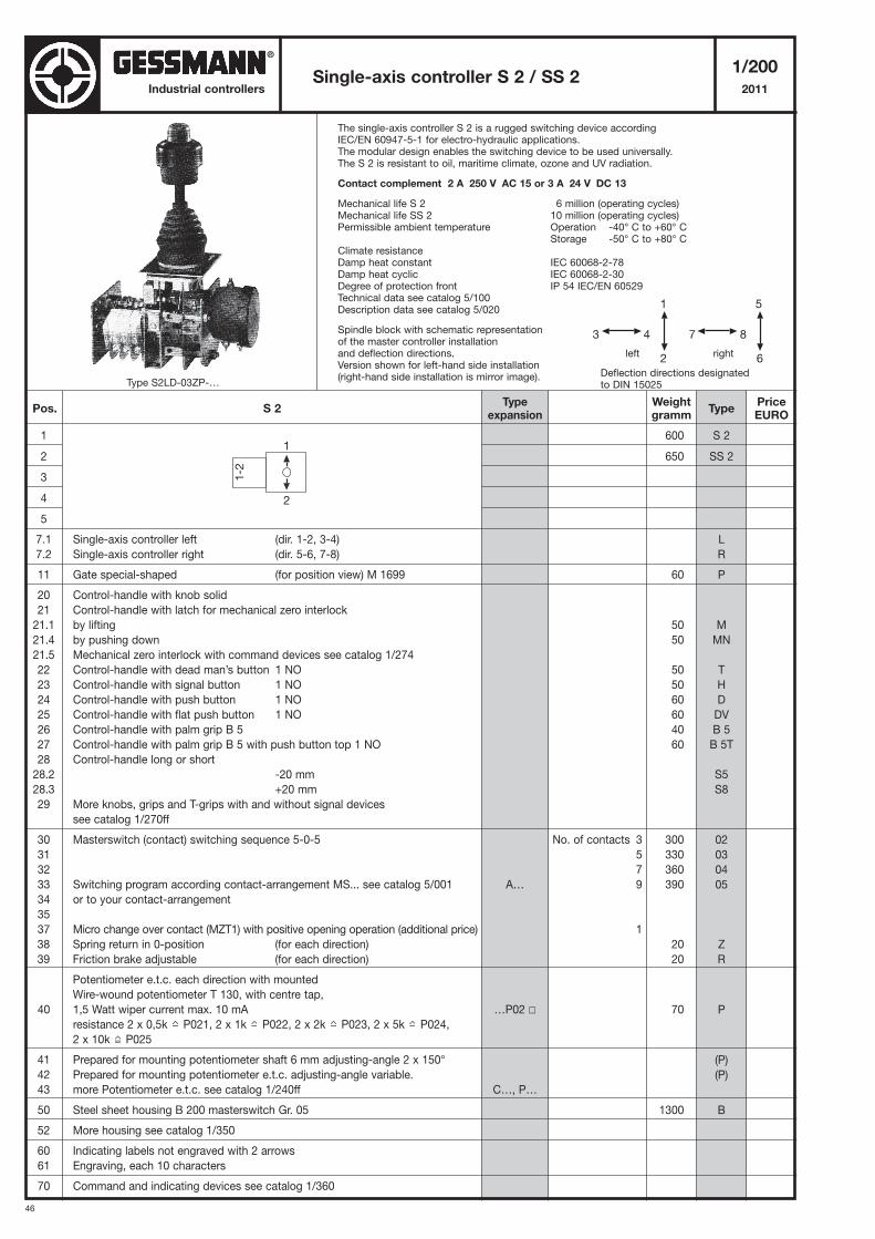
The single-axis controller S 2 is a rugged switching device accordingIEC/EN 60947-5-1 for electro-hydraulic applications.The modular design enables the switching device to be used universally.The S 2 is resistant to oil, maritime climate, ozone and UV radiation.
Contact complement 2 A 250 V AC 15 or 3 A 24 V DC 13
Mechanical life S 2 6 million (operating cycles)Mechanical life SS 2 10 million (operating cycles)Permissible ambient temperature Operation -40° C to +60° C
Storage -50° C to +80° CClimate resistanceDamp heat constant IEC 60068-2-78Damp heat cyclic IEC 60068-2-30Degree of protection front IP 54 IEC/EN 60529Technical data see catalog 5/100Description data see catalog 5/020
Spindle block with schematic representationof the master controller installationand deflection directions.Version shown for left-hand side installation(right-hand side installation is mirror image).
Single-axis controller S 2 / SS 21/200
2011
1
2
3
4
5
7.1 Single-axis controller left (dir. 1-2, 3-4)
7.2 Single-axis controller right (dir. 5-6, 7-8)
11 Gate special-shaped (for position view) M 1699
20 Control-handle with knob solid
21 Control-handle with latch for mechanical zero interlock
21.1 by lifting
21.4 by pushing down
21.5 Mechanical zero interlock with command devices see catalog 1/274
22 Control-handle with dead man’s button 1 NO
23 Control-handle with signal button 1 NO
24 Control-handle with push button 1 NO
25 Control-handle with flat push button 1 NO
26 Control-handle with palm grip B 5
27 Control-handle with palm grip B 5 with push button top 1 NO
28 Control-handle long or short
28.2 -20 mm
28.3 +20 mm
29 More knobs, grips and T-grips with and without signal devices
see catalog 1/270ff
30 Masterswitch (contact) switching sequence 5-0-5
31
32
33 Switching program according contact-arrangement MS... see catalog 5/001
34 or to your contact-arrangement
35
37 Micro change over contact (MZT1) with positive opening operation (additional price)
38 Spring return in 0-position (for each direction)
39 Friction brake adjustable (for each direction)
Potentiometer e.t.c. each direction with mounted
Wire-wound potentiometer T 130, with centre tap,
40 1,5 Watt wiper current max. 10 mA
resistance 2 x 0,5k P021, 2 x 1k P022, 2 x 2k P023, 2 x 5k P024,
2 x 10k P025
41 Prepared for mounting potentiometer shaft 6 mm adjusting-angle 2 x 150°
42 Prepared for mounting potentiometer e.t.c. adjusting-angle variable.
43 more Potentiometer e.t.c. see catalog 1/240ff
50 Steel sheet housing B 200 masterswitch Gr. 05
52 More housing see catalog 1/350
60 Indicating labels not engraved with 2 arrows
61 Engraving, each 10 characters
70 Command and indicating devices see catalog 1/360
600
650
60
50
50
50
50
60
60
40
60
300
330
360
390
20
20
70
1300
S 2
SS 2
L
R
P
M
MN
T
H
D
DV
B 5
B 5T
S5
S8
02
03
04
05
Z
R
P
(P)
(P)
B
5
7 8
6
1
3 4
2
Deflection directions designatedto DIN 15025
left right
Pos. S 2Weightgramm
Typeexpansion
TypePriceEURO
No. of contacts 3
5
7
9
1
A…
…P02 �
C…, P…
1
1-2
2
Type S2LD-03ZP-…
115,-
181,-
63,-
36,-
48,-
38,-
38,-
41,-
46,-
24,-
74,-
14,-
66,-
90,-
114,-
138,-
13,-
20,-
20,-
139,-
58,-
129,-
136,-
9,-
10,-
®
47
Single-axis controller S 2 / SS 21/201
2011Industrial controllers
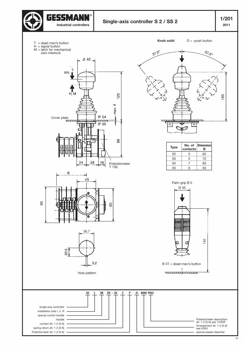
Cover plate
PotentiometerT 130
Hole pattern
Palm grip B 5
Ø 35
B 5T = dead man’s button
145
Knob solid D = -push button
TypeNo. of Dimension
contacts B
02 3 62
03 5 72
04 7 83
05 9 93
T = dead man’s buttonH = signal buttonM = latch for mechanical
zero interlock
36,7
S2 L S8 DV - 02 Z P -X- A050 P023
single-axis controller
installation side L o. R
special control handle
handle
contact dir. 1-2 (5-6)
spring return dir. 1-2 (5-6)
Potentiometer dir. 1-2 (5-6)
Potentiometer descriptiondir. 1-2 (5-6) see 1/240ff
Arrangement dir. 1-2 (5-6) see 5/001
special please describe
MN
®
48
Industrial controllers
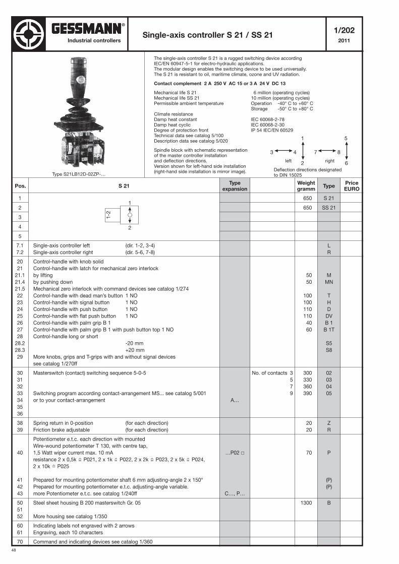
The single-axis controller S 21 is a rugged switching device accordingIEC/EN 60947-5-1 for electro-hydraulic applications.The modular design enables the switching device to be used universally.The S 21 is resistant to oil, maritime climate, ozone and UV radiation.
Contact complement 2 A 250 V AC 15 or 3 A 24 V DC 13
Mechanical life S 21 6 million (operating cycles)Mechanical life SS 21 10 million (operating cycles)Permissible ambient temperature Operation -40° C to +60° C
Storage -50° C to +80° CClimate resistanceDamp heat constant IEC 60068-2-78Damp heat cyclic IEC 60068-2-30Degree of protection front IP 54 IEC/EN 60529Technical data see catalog 5/100Description data see catalog 5/020
Spindle block with schematic representationof the master controller installationand deflection directions.Version shown for left-hand side installation(right-hand side installation is mirror image).
Single-axis controller S 21 / SS 211/202
2011
1
2
3
4
5
7.1 Single-axis controller left (dir. 1-2, 3-4)
7.2 Single-axis controller right (dir. 5-6, 7-8)
20 Control-handle with knob solid
21 Control-handle with latch for mechanical zero interlock
21.1 by lifting
21.4 by pushing down
21.5 Mechanical zero interlock with command devices see catalog 1/274
22 Control-handle with dead man’s button 1 NO
23 Control-handle with signal button 1 NO
24 Control-handle with push button 1 NO
25 Control-handle with flat push button 1 NO
26 Control-handle with palm grip B 1
27 Control-handle with palm grip B 1 with push button top 1 NO
28 Control-handle long or short
28.2 -20 mm
28.3 +20 mm
29 More knobs, grips and T-grips with and without signal devices
see catalog 1/270ff
30 Masterswitch (contact) switching sequence 5-0-5
31
32
33 Switching program according contact-arrangement MS... see catalog 5/001
34 or to your contact-arrangement
35
36
38 Spring return in 0-position (for each direction)
39 Friction brake adjustable (for each direction)
Potentiometer e.t.c. each direction with mounted
Wire-wound potentiometer T 130, with centre tap,
40 1,5 Watt wiper current max. 10 mA
resistance 2 x 0,5k P021, 2 x 1k P022, 2 x 2k P023, 2 x 5k P024,
2 x 10k P025
41 Prepared for mounting potentiometer shaft 6 mm adjusting-angle 2 x 150°
42 Prepared for mounting potentiometer e.t.c. adjusting-angle variable.
43 more Potentiometer e.t.c. see catalog 1/240ff
50 Steel sheet housing B 200 masterswitch Gr. 05
51
52 More housing see catalog 1/350
60 Indicating labels not engraved with 2 arrows
61 Engraving, each 10 characters
70 Command and indicating devices see catalog 1/360
650
650
50
50
100
100
110
110
40
60
300
330
360
390
20
20
70
1300
S 21
SS 21
L
R
M
MN
T
H
D
DV
B 1
B 1T
S5
S8
02
03
04
05
Z
R
P
(P)
(P)
B
5
7 8
6
1
3 4
2
Deflection directions designatedto DIN 15025
left right
1
1-2
2
Pos. S 21Weightgramm
Typeexpansion
TypePriceEURO
No. of contacts 3
5
7
9
A…
…P02 �
C…, P…
Type S21LB12D-02ZP-…
139,-
203,-
36,-
48,-
38,-
38,-
41,-
46,-
24,-
74,-
14,-
66,-
90,-
114,-
138,-
20,-
20,-
139,-
58,-
129,-
136,-
9,-
10,-
®
49
Single-axis controller S 21 / SS 211/203
2011Industrial controllers
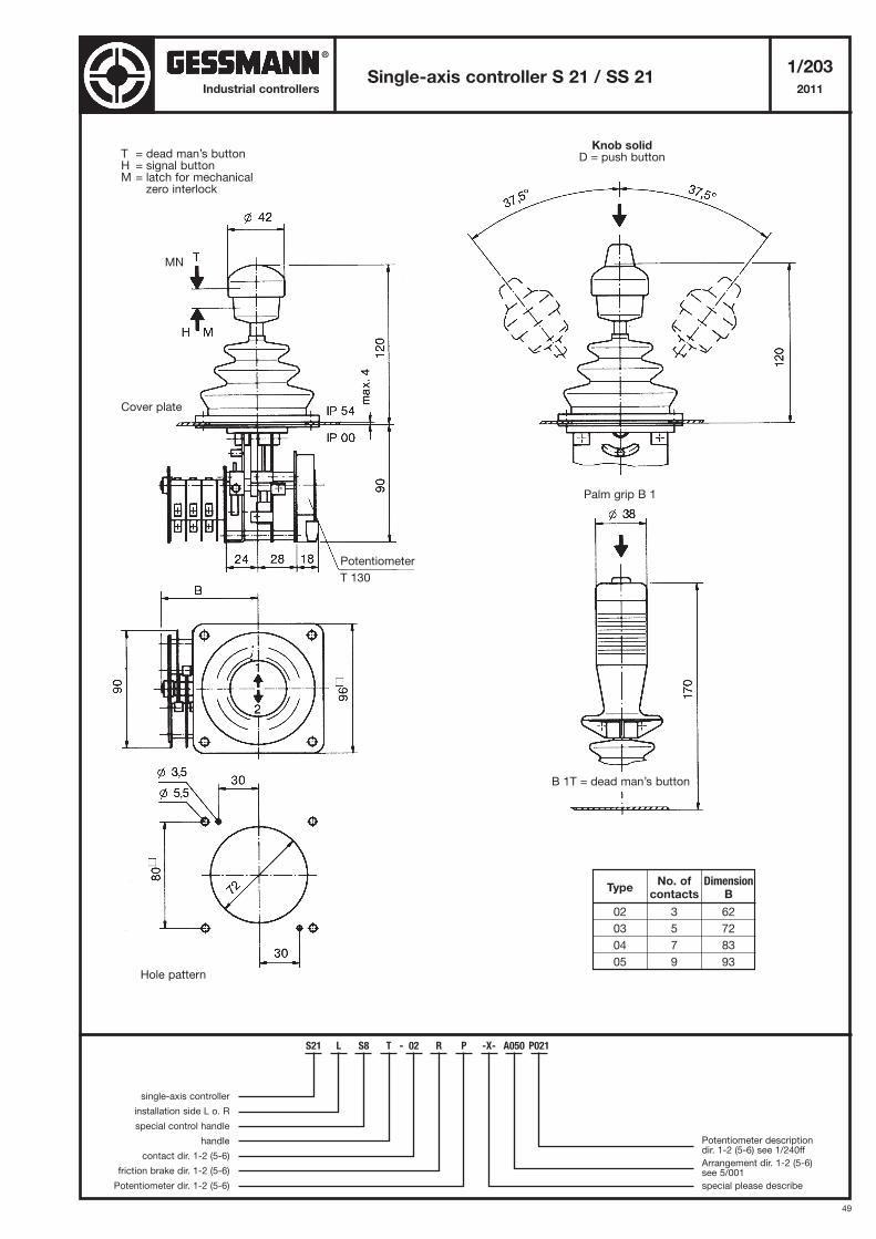
Cover plate
Hole pattern
Palm grip B 1
B 1T = dead man’s button
Knob solidD = push button
TypeNo. of Dimension
contacts B
02 3 62
03 5 72
04 7 83
05 9 93
T = dead man’s buttonH = signal buttonM = latch for mechanical
zero interlock
Potentiometer
T 130
S21 L S8 T - 02 R P -X- A050 P021
single-axis controller
installation side L o. R
special control handle
handle
contact dir. 1-2 (5-6)
friction brake dir. 1-2 (5-6)
Potentiometer dir. 1-2 (5-6)
Potentiometer descriptiondir. 1-2 (5-6) see 1/240ff
Arrangement dir. 1-2 (5-6) see 5/001
special please describe
MN
®
50
Industrial controllers
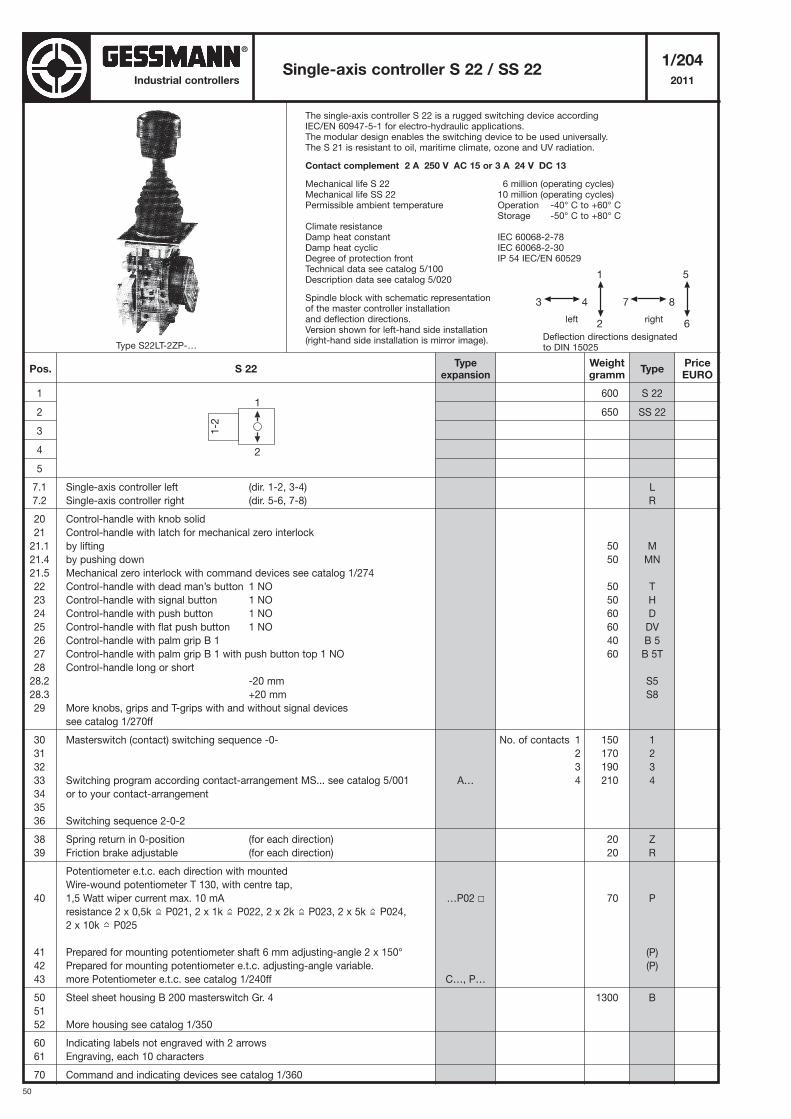
The single-axis controller S 22 is a rugged switching device accordingIEC/EN 60947-5-1 for electro-hydraulic applications.The modular design enables the switching device to be used universally.The S 21 is resistant to oil, maritime climate, ozone and UV radiation.
Contact complement 2 A 250 V AC 15 or 3 A 24 V DC 13
Mechanical life S 22 6 million (operating cycles)Mechanical life SS 22 10 million (operating cycles)Permissible ambient temperature Operation -40° C to +60° C
Storage -50° C to +80° CClimate resistanceDamp heat constant IEC 60068-2-78Damp heat cyclic IEC 60068-2-30Degree of protection front IP 54 IEC/EN 60529Technical data see catalog 5/100Description data see catalog 5/020
Spindle block with schematic representationof the master controller installationand deflection directions.Version shown for left-hand side installation(right-hand side installation is mirror image).
Single-axis controller S 22 / SS 221/204
2011
1
2
3
4
5
7.1 Single-axis controller left (dir. 1-2, 3-4)
7.2 Single-axis controller right (dir. 5-6, 7-8)
20 Control-handle with knob solid
21 Control-handle with latch for mechanical zero interlock
21.1 by lifting
21.4 by pushing down
21.5 Mechanical zero interlock with command devices see catalog 1/274
22 Control-handle with dead man’s button 1 NO
23 Control-handle with signal button 1 NO
24 Control-handle with push button 1 NO
25 Control-handle with flat push button 1 NO
26 Control-handle with palm grip B 1
27 Control-handle with palm grip B 1 with push button top 1 NO
28 Control-handle long or short
28.2 -20 mm
28.3 +20 mm
29 More knobs, grips and T-grips with and without signal devices
see catalog 1/270ff
30 Masterswitch (contact) switching sequence -0-
31
32
33 Switching program according contact-arrangement MS... see catalog 5/001
34 or to your contact-arrangement
35
36 Switching sequence 2-0-2
38 Spring return in 0-position (for each direction)
39 Friction brake adjustable (for each direction)
Potentiometer e.t.c. each direction with mounted
Wire-wound potentiometer T 130, with centre tap,
40 1,5 Watt wiper current max. 10 mA
resistance 2 x 0,5k P021, 2 x 1k P022, 2 x 2k P023, 2 x 5k P024,
2 x 10k P025
41 Prepared for mounting potentiometer shaft 6 mm adjusting-angle 2 x 150°
42 Prepared for mounting potentiometer e.t.c. adjusting-angle variable.
43 more Potentiometer e.t.c. see catalog 1/240ff
50 Steel sheet housing B 200 masterswitch Gr. 4
51
52 More housing see catalog 1/350
60 Indicating labels not engraved with 2 arrows
61 Engraving, each 10 characters
70 Command and indicating devices see catalog 1/360
600
650
50
50
50
50
60
60
40
60
150
170
190
210
20
20
70
1300
S 22
SS 22
L
R
M
MN
T
H
D
DV
B 5
B 5T
S5
S8
1
2
3
4
Z
R
P
(P)
(P)
B
5
7 8
6
1
3 4
2
Deflection directions designatedto DIN 15025
left right
1
1-2
2
Pos. S 22Weightgramm
Typeexpansion
TypePriceEURO
No. of contacts 1
2
3
4A…
…P02 �
C…, P…
Type S22LT-2ZP-…
115,-
181,-
36,-
48,-
38,-
38,-
41,-
46,-
24,-
74,-
14,-
28,-
40,-
52,-
64,-
34,-
20,-
20,-
139,-
58,-
129,-
136,-
9,-
10,-
®
51
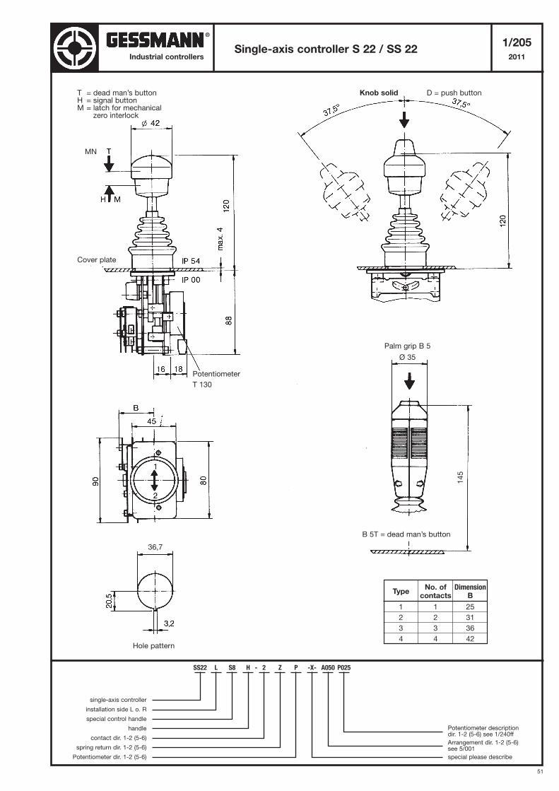
Single-axis controller S 22 / SS 221/205
2011Industrial controllers
Cover plate
Hole pattern
TypeNo. of Dimension
contacts B
1 1 25
2 2 31
3 3 36
4 4 42
Potentiometer
T 130
Knob solid D = push buttonT = dead man’s buttonH = signal buttonM = latch for mechanical
zero interlock
36,7
B 5T = dead man’s button
145
Palm grip B 5
Ø 35
SS22 L S8 H - 2 Z P -X- A050 P025
single-axis controller
installation side L o. R
special control handle
handle
contact dir. 1-2 (5-6)
spring return dir. 1-2 (5-6)
Potentiometer dir. 1-2 (5-6)
Potentiometer descriptiondir. 1-2 (5-6) see 1/240ff
Arrangement dir. 1-2 (5-6) see 5/001
special please describe
MN
®
52
Industrial controllers
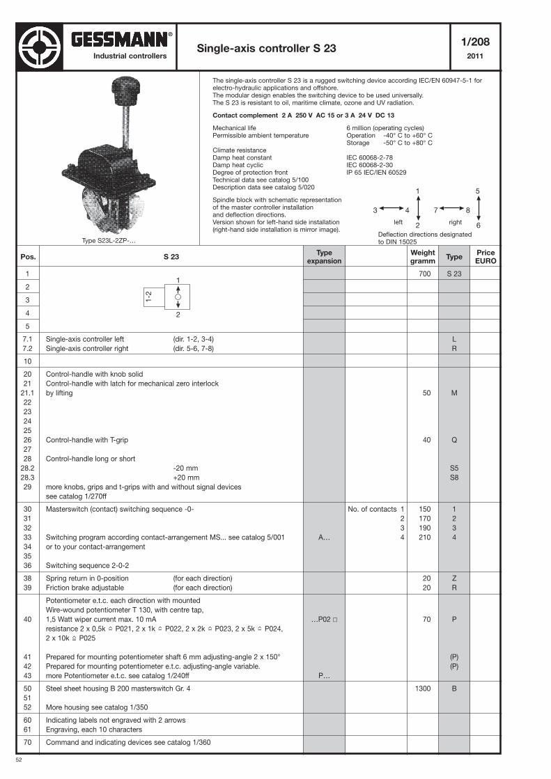
The single-axis controller S 23 is a rugged switching device according IEC/EN 60947-5-1 forelectro-hydraulic applications and offshore.The modular design enables the switching device to be used universally.The S 23 is resistant to oil, maritime climate, ozone and UV radiation.
Contact complement 2 A 250 V AC 15 or 3 A 24 V DC 13
Mechanical life 6 million (operating cycles)Permissible ambient temperature Operation -40° C to +60° C
Storage -50° C to +80° CClimate resistanceDamp heat constant IEC 60068-2-78Damp heat cyclic IEC 60068-2-30Degree of protection front IP 65 IEC/IEN 60529Technical data see catalog 5/100Description data see catalog 5/020
Spindle block with schematic representationof the master controller installationand deflection directions.Version shown for left-hand side installation(right-hand side installation is mirror image).
Single-axis controller S 231/208
2011
1
2
3
4
5
7.1 Single-axis controller left (dir. 1-2, 3-4)
7.2 Single-axis controller right (dir. 5-6, 7-8)
10
20 Control-handle with knob solid
21 Control-handle with latch for mechanical zero interlock
21.1 by lifting
22
23
24
25
26 Control-handle with T-grip
27
28 Control-handle long or short
28.2 -20 mm
28.3 +20 mm
29 more knobs, grips and t-grips with and without signal devices
see catalog 1/270ff
30 Masterswitch (contact) switching sequence -0-
31
32
33 Switching program according contact-arrangement MS... see catalog 5/001
34 or to your contact-arrangement
35
36 Switching sequence 2-0-2
38 Spring return in 0-position (for each direction)
39 Friction brake adjustable (for each direction)
Potentiometer e.t.c. each direction with mounted
Wire-wound potentiometer T 130, with centre tap,
40 1,5 Watt wiper current max. 10 mA
resistance 2 x 0,5k P021, 2 x 1k P022, 2 x 2k P023, 2 x 5k P024,
2 x 10k P025
41 Prepared for mounting potentiometer shaft 6 mm adjusting-angle 2 x 150°
42 Prepared for mounting potentiometer e.t.c. adjusting-angle variable.
43 more Potentiometer e.t.c. see catalog 1/240ff
50 Steel sheet housing B 200 masterswitch Gr. 4
51
52 More housing see catalog 1/350
60 Indicating labels not engraved with 2 arrows
61 Engraving, each 10 characters
70 Command and indicating devices see catalog 1/360
700
50
40
150
170
190
210
20
20
70
1300
S 23
L
R
M
Q
S5
S8
1
2
3
4
Z
R
P
(P)
(P)
B
5
7 8
6
1
3 4
2
Deflection directions designatedto DIN 15025
left right
1
1-2
2
Pos. S 23Weightgramm
Typeexpansion
TypePriceEURO
No. of contacts 1
2
3
4A…
…P02 �
P…
Type S23L-2ZP-…
191,-
50,-
24,-
14,-
28,-
40,-
52,-
64,-
34,-
20,-
20,-
139,-
58,-
129,-
136,-
9,-
10,-
®
53
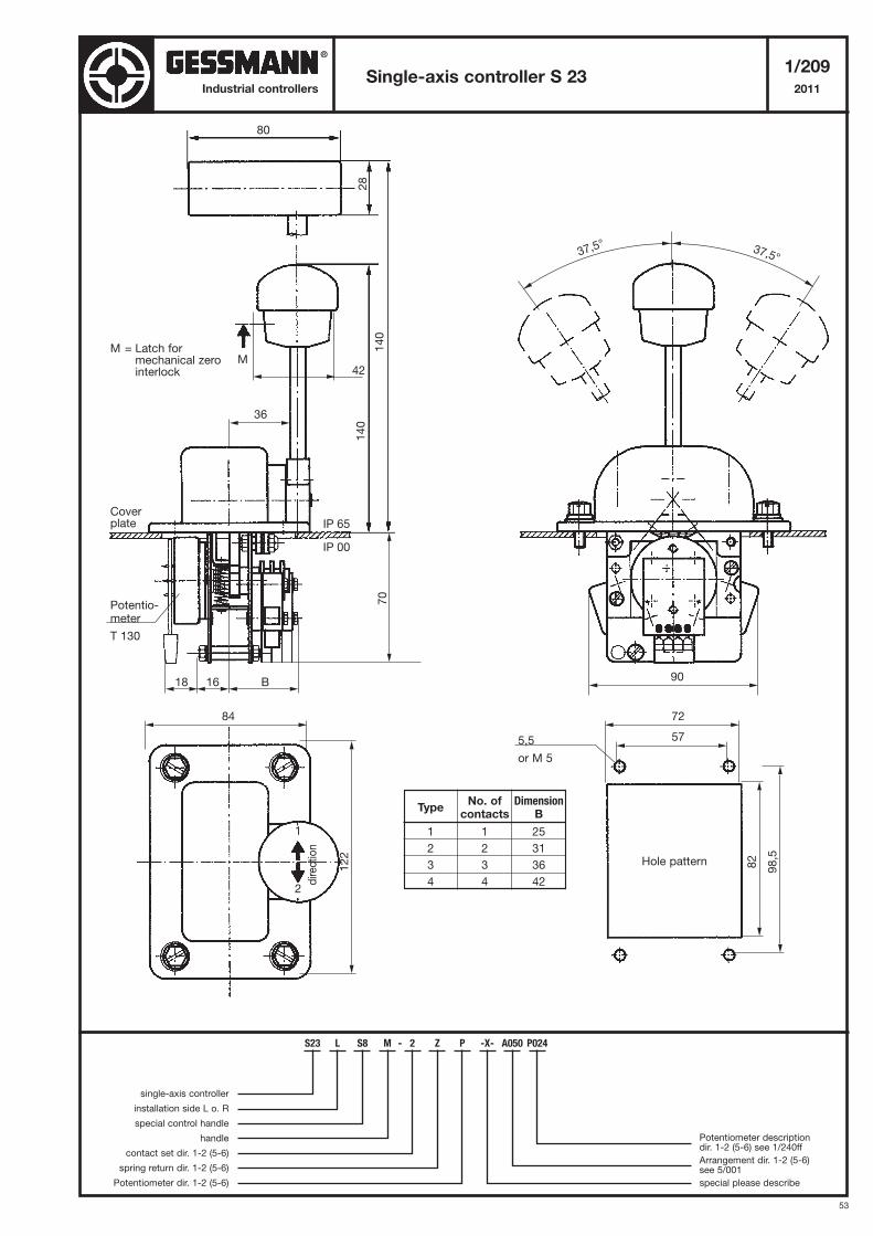
Single-axis controller S 231/209
2011Industrial controllers
Coverplate
Hole pattern
TypeNo. of Dimension
contacts B
1 1 25
2 2 31
3 3 36
4 4 42
M = Latch formechanical zerointerlock
Potentio-meter
T 130
5,5
or M 5
direction
S23 L S8 M - 2 Z P -X- A050 P024
single-axis controller
installation side L o. R
special control handle
handle
contact set dir. 1-2 (5-6)
spring return dir. 1-2 (5-6)
Potentiometer dir. 1-2 (5-6)
Potentiometer descriptiondir. 1-2 (5-6) see 1/240ff
Arrangement dir. 1-2 (5-6) see 5/001
special please describe
®
54
Industrial controllers
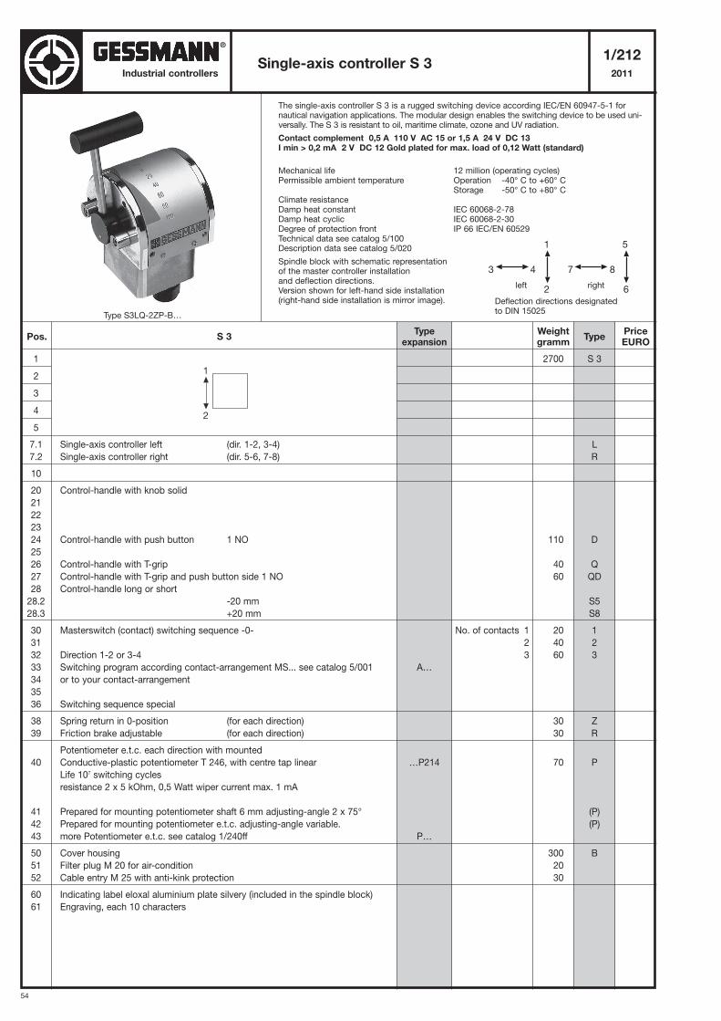
The single-axis controller S 3 is a rugged switching device according IEC/EN 60947-5-1 fornautical navigation applications. The modular design enables the switching device to be used uni-versally. The S 3 is resistant to oil, maritime climate, ozone and UV radiation.
Contact complement 0,5 A 110 V AC 15 or 1,5 A 24 V DC 13 I min > 0,2 mA 2 V DC 12 Gold plated for max. load of 0,12 Watt (standard)
Mechanical life 12 million (operating cycles)Permissible ambient temperature Operation -40° C to +60° C
Storage -50° C to +80° CClimate resistanceDamp heat constant IEC 60068-2-78Damp heat cyclic IEC 60068-2-30Degree of protection front IP 66 IEC/EN 60529Technical data see catalog 5/100Description data see catalog 5/020
Spindle block with schematic representationof the master controller installationand deflection directions.Version shown for left-hand side installation(right-hand side installation is mirror image).
Single-axis controller S 31/212
2011
1
2
3
4
5
7.1 Single-axis controller left (dir. 1-2, 3-4)
7.2 Single-axis controller right (dir. 5-6, 7-8)
10
20 Control-handle with knob solid
21
22
23
24 Control-handle with push button 1 NO
25
26 Control-handle with T-grip
27 Control-handle with T-grip and push button side 1 NO
28 Control-handle long or short
28.2 -20 mm
28.3 +20 mm
30 Masterswitch (contact) switching sequence -0-
31
32 Direction 1-2 or 3-4
33 Switching program according contact-arrangement MS... see catalog 5/001
34 or to your contact-arrangement
35
36 Switching sequence special
38 Spring return in 0-position (for each direction)
39 Friction brake adjustable (for each direction)
Potentiometer e.t.c. each direction with mounted
40 Conductive-plastic potentiometer T 246, with centre tap linear
Life 107 switching cycles
resistance 2 x 5 kOhm, 0,5 Watt wiper current max. 1 mA
41 Prepared for mounting potentiometer shaft 6 mm adjusting-angle 2 x 75°
42 Prepared for mounting potentiometer e.t.c. adjusting-angle variable.
43 more Potentiometer e.t.c. see catalog 1/240ff
50 Cover housing
51 Filter plug M 20 for air-condition
52 Cable entry M 25 with anti-kink protection
60 Indicating label eloxal aluminium plate silvery (included in the spindle block)
61 Engraving, each 10 characters
2700
110
40
60
20
40
60
30
30
70
300
20
30
S 3
L
R
D
Q
QD
S5
S8
1
2
3
Z
R
P
(P)
(P)
B
5
7 8
6
1
3 4
2
Deflection directions designatedto DIN 15025
left right
1
2
Pos. S 3Weightgramm
Typeexpansion
TypePriceEURO
No. of contacts 1
2
3
A…
…P214
P…
Type S3LQ-2ZP-B…
411,-
62,-
24,-
74,-
14,-
37,-
52,-
67,-
34,-
27,-
27,-
139,-
58,-
129,-
45,-
14,-
16,-
10,-
®
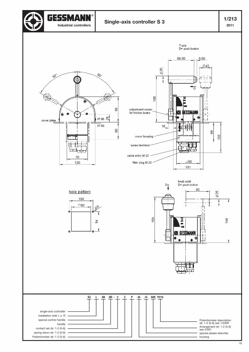
55
Single-axis controller S 31/213
2011Industrial controllers
S3 L S8 QD - 2 Z P -B- -X- A05 P214
single-axis controller
installation side L o. R
special control handle
handle
contact set dir. 1-2 (5-6)
spring return dir. 1-2 (5-6)
Potentiometer dir. 1-2 (5-6)
Potentiometer descriptiondir. 1-2 (5-6) see 1/240ff
Arrangement dir. 1-2 (5-6) see 5/001
special please describe
housing
®
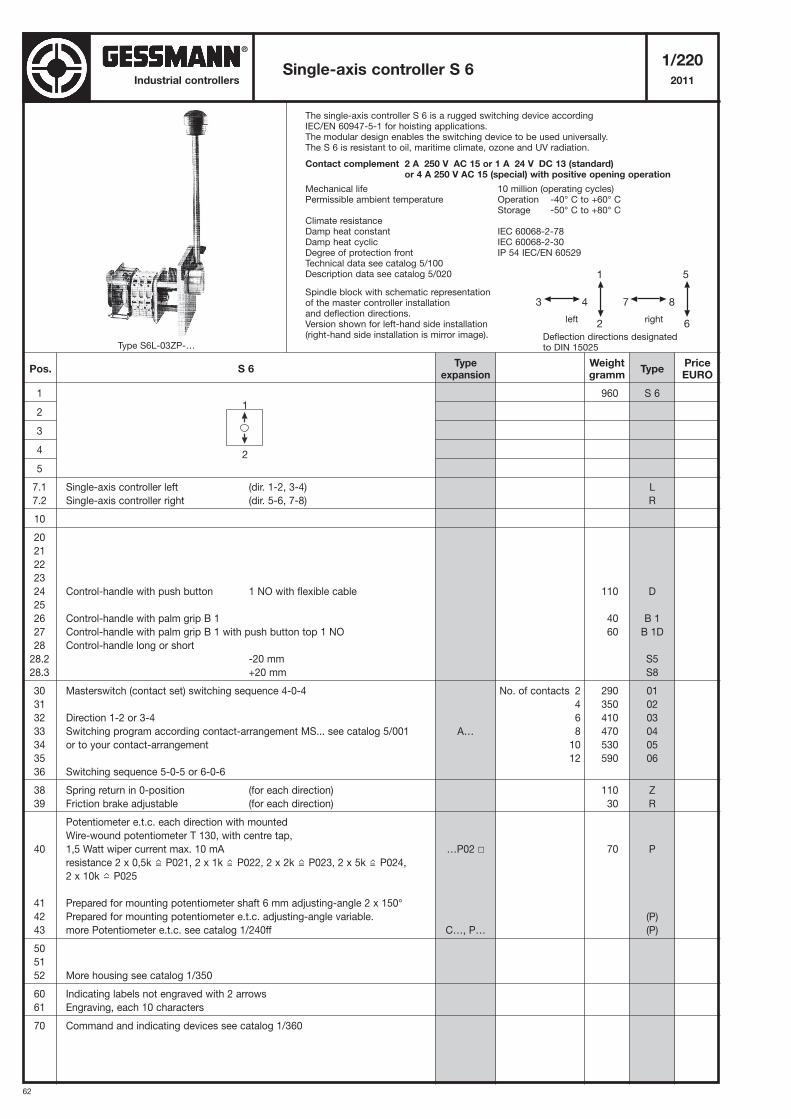
62
Industrial controllers
The single-axis controller S 6 is a rugged switching device according IEC/EN 60947-5-1 for hoisting applications.The modular design enables the switching device to be used universally.The S 6 is resistant to oil, maritime climate, ozone and UV radiation.
Contact complement 2 A 250 V AC 15 or 1 A 24 V DC 13 (standard) or 4 A 250 V AC 15 (special) with positive opening operation
Mechanical life 10 million (operating cycles)Permissible ambient temperature Operation -40° C to +60° C
Storage -50° C to +80° CClimate resistanceDamp heat constant IEC 60068-2-78Damp heat cyclic IEC 60068-2-30Degree of protection front IP 54 IEC/EN 60529Technical data see catalog 5/100Description data see catalog 5/020
Spindle block with schematic representationof the master controller installationand deflection directions.Version shown for left-hand side installation(right-hand side installation is mirror image).
Single-axis controller S 61/220
2011
1
2
3
4
5
7.1 Single-axis controller left (dir. 1-2, 3-4)
7.2 Single-axis controller right (dir. 5-6, 7-8)
10
20
21
22
23
24 Control-handle with push button 1 NO with flexible cable
25
26 Control-handle with palm grip B 1
27 Control-handle with palm grip B 1 with push button top 1 NO
28 Control-handle long or short
28.2 -20 mm
28.3 +20 mm
30 Masterswitch (contact set) switching sequence 4-0-4
31
32 Direction 1-2 or 3-4
33 Switching program according contact-arrangement MS... see catalog 5/001
34 or to your contact-arrangement
35
36 Switching sequence 5-0-5 or 6-0-6
38 Spring return in 0-position (for each direction)
39 Friction brake adjustable (for each direction)
Potentiometer e.t.c. each direction with mounted
Wire-wound potentiometer T 130, with centre tap,
40 1,5 Watt wiper current max. 10 mA
resistance 2 x 0,5k P021, 2 x 1k P022, 2 x 2k P023, 2 x 5k P024,
2 x 10k P025
41 Prepared for mounting potentiometer shaft 6 mm adjusting-angle 2 x 150°
42 Prepared for mounting potentiometer e.t.c. adjusting-angle variable.
43 more Potentiometer e.t.c. see catalog 1/240ff
50
51
52 More housing see catalog 1/350
60 Indicating labels not engraved with 2 arrows
61 Engraving, each 10 characters
70 Command and indicating devices see catalog 1/360
960
110
40
60
290
350
410
470
530
590
110
30
70
S 6
L
R
D
B 1
B 1D
S5
S8
01
02
03
04
05
06
Z
R
P
(P)
(P)
5
7 8
6
1
3 4
2
Deflection directions designatedto DIN 15025
left right
1
2
Pos. S 6Weightgramm
Typeexpansion
TypePriceEURO
No. of contacts 2
4
6
8
10
12
A…
…P02 �
C…, P…
Type S6L-03ZP-…
191,-
62,-
24,-
76,-
14,-
59,-
89,-
119,-
149,-
179,-
209,-
34,-
27,-
27,-
139,-
58,-
129,-
9,-
10,-
®
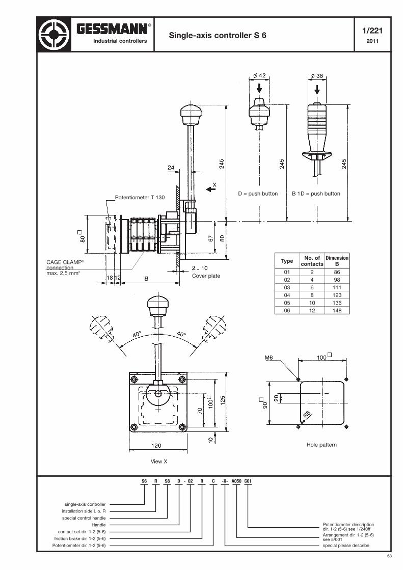
63
Single-axis controller S 61/221
2011Industrial controllers
Cover plate
Hole pattern
View X
TypeNo. of Dimension
contacts B
01 2 86
02 4 98
03 6 111
04 8 123
05 10 136
06 12 148
Potentiometer T 130D = push button B 1D = push button
S6 R S8 D - 02 R C -X- A050 C01
single-axis controller
installation side L o. R
special control handle
Handle
contact set dir. 1-2 (5-6)
friction brake dir. 1-2 (5-6)
Potentiometer dir. 1-2 (5-6)
Potentiometer descriptiondir. 1-2 (5-6) see 1/240ff
Arrangement dir. 1-2 (5-6) see 5/001
special please describe
CAGE CLAMP®
connectionmax. 2,5 mm2
®