Embed Size (px)
Citation preview
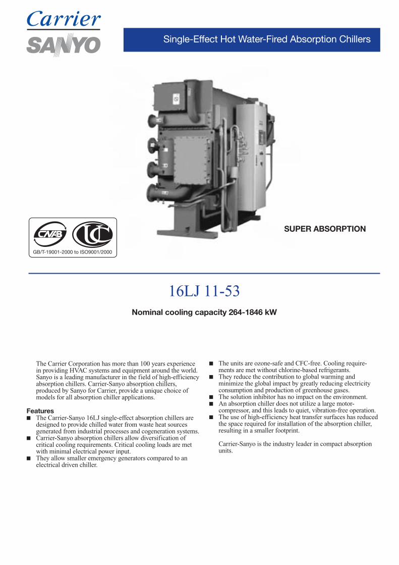
Single-Effect Hot Water-Fired Absorption Chillers
The Carrier Corporation has more than 100 years experiencein providing HVAC systems and equipment around the world.Sanyo is a leading manufacturer in the field of high-efficiencyabsorption chillers. Carrier-Sanyo absorption chillers,produced by Sanyo for Carrier, provide a unique choice ofmodels for all absorption chiller applications.
Features■ The Carrier-Sanyo 16LJ single-effect absorption chillers are
designed to provide chilled water from waste heat sourcesgenerated from industrial processes and cogeneration systems.
■ Carrier-Sanyo absorption chillers allow diversification ofcritical cooling requirements. Critical cooling loads are metwith minimal electrical power input.
■ They allow smaller emergency generators compared to anelectrical driven chiller.
16LJ 11-53Nominal cooling capacity 264-1846 kW
GB/T-19001-2000 to ISO9001/2000
SUPER ABSORPTION
■ The units are ozone-safe and CFC-free. Cooling require-ments are met without chlorine-based refrigerants.
■ They reduce the contribution to global warming andminimize the global impact by greatly reducing electricityconsumption and production of greenhouse gases.
■ The solution inhibitor has no impact on the environment.■ An absorption chiller does not utilize a large motor-
compressor, and this leads to quiet, vibration-free operation.■ The use of high-efficiency heat transfer surfaces has reduced
the space required for installation of the absorption chiller,resulting in a smaller footprint.
Carrier-Sanyo is the industry leader in compact absorptionunits.
2
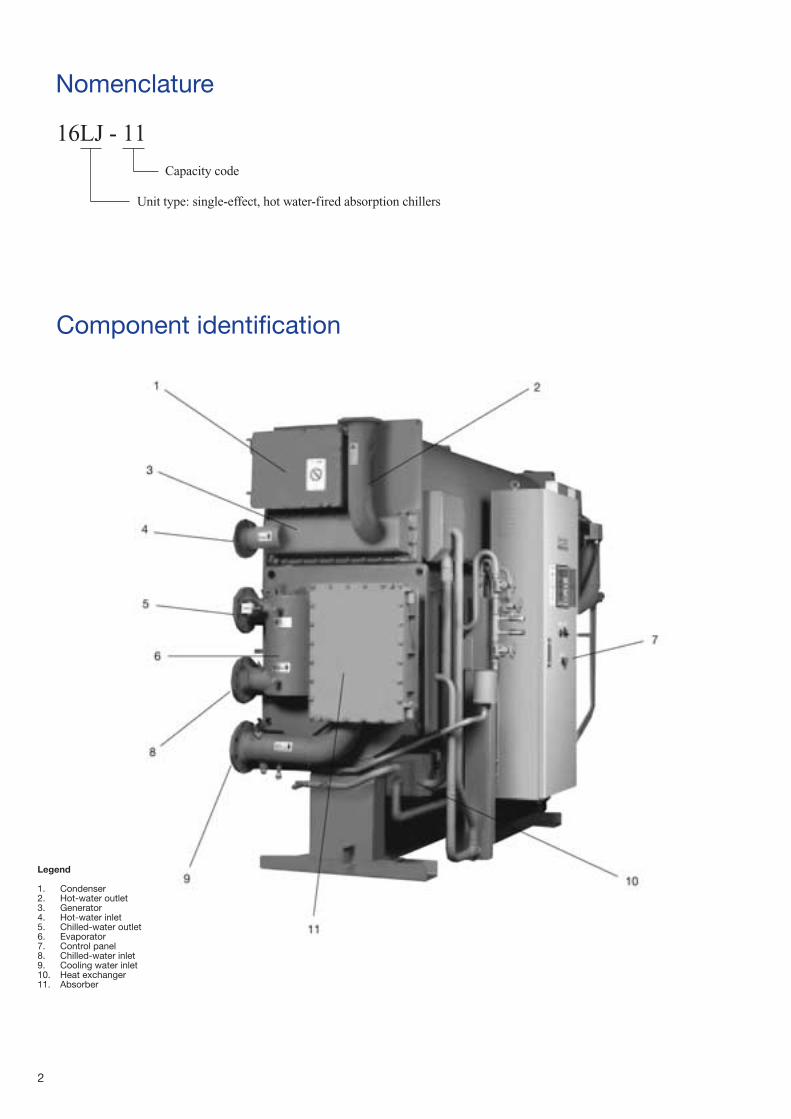
Nomenclature
Component identification
16LJ - 11
Unit type: single-effect, hot water-fired absorption chillers
Capacity code
Legend
1. Condenser2. Hot-water outlet3. Generator4. Hot-water inlet5. Chilled-water outlet6. Evaporator7. Control panel8. Chilled-water inlet9. Cooling water inlet10. Heat exchanger11. Absorber
3
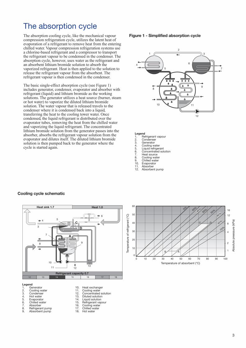
The absorption cycleThe absorption cooling cycle, like the mechanical vapourcompression refrigeration cycle, utilizes the latent heat ofevaporation of a refrigerant to remove heat from the enteringchilled water. Vapour compression refrigeration systems usea chlorine-based refrigerant and a compressor to transportthe refrigerant vapour to be condensed in the condenser. Theabsorption cycle, however, uses water as the refrigerant andan absorbent lithium bromide solution to absorb thevaporized refrigerant. Heat is then applied to the solution torelease the refrigerant vapour from the absorbent. Therefrigerant vapour is then condensed in the condenser.
The basic single-effect absorption cycle (see Figure 1)includes generator, condenser, evaporator and absorber withrefrigerant (liquid) and lithium bromide as the workingsolutions. The generator utilizes a heat source (burner, steamor hot water) to vaporize the diluted lithium bromidesolution. The water vapour that is released travels to thecondenser where it is condensed back into a liquid,transferring the heat to the cooling tower water. Oncecondensed, the liquid refrigerant is distributed over theevaporator tubes, removing the heat from the chilled waterand vaporizing the liquid refrigerant. The concentratedlithium bromide solution from the generator passes into theabsorber, absorbs the refrigerant vapour solution from theevaporator and dilutes itself. The diluted lithium bromidesolution is then pumped back to the generator where thecycle is started again.
Cooling cycle schematic
Heat sink 1.7 Heat 1.0
12 13 14 15 16 17 18
Legend1. Refrigerant vapour2. Condenser3. Generator4. Cooling water5. Liquid refrigerant6. Concentrated solution7. Heat source8. Cooling water9. Chilled water10. Evaporator11. Absorber12. Absorbent pump
Legend1. Generator2. Cooling water3. Condenser4. Hot water5. Evaporator6. Chilled water7. Absorber8. Refrigerant pump9. Absorbent pump
10. Heat exchanger11. Cooling water12. Concentrated solution13. Diluted solution14. Liquid solution15. Refrigerant vapour16. Cooling water17. Chilled water18. Hot water
0 10 20 30 40 50 60 70 80 90 100 0
10
20
30
40
50
60
1
4
8
12
160%
40%
50%
55%
70%
45%
60%
65%
A B
C D
2
Tem
per
atur
e of
ref
riger
ant
(°C
)
Ab
solu
te p
rees
sure
(kP
a)
Temperature of absorbent (°C)
Figure 1 - Simplified absorption cycle
Refrigerant capacity 0.7
44
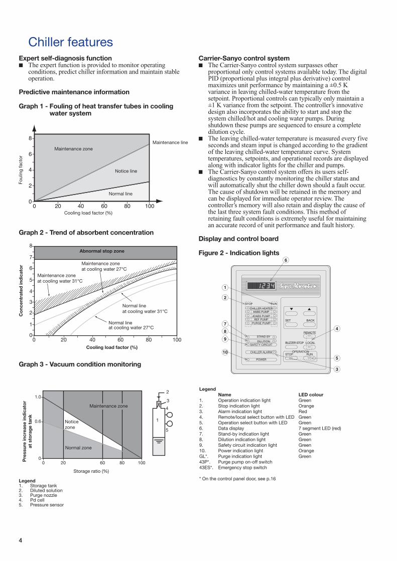
Chiller featuresExpert self-diagnosis function ■ The expert function is provided to monitor operating
conditions, predict chiller information and maintain stableoperation.
Predictive maintenance information
Graph 1 - Fouling of heat transfer tubes in coolingwater system
Graph 2 - Trend of absorbent concentration
Graph 3 - Vacuum condition monitoring
Legend1. Storage tank2. Diluted solution3. Purge nozzle4. Pd cell5. Pressure sensor
Carrier-Sanyo control system■ The Carrier-Sanyo control system surpasses other
proportional only control systems available today. The digitalPID (proportional plus integral plus derivative) controlmaximizes unit performance by maintaining a ±0.5 Kvariance in leaving chilled-water temperature from thesetpoint. Proportional controls can typically only maintain a±1 K variance from the setpoint. The controller’s innovativedesign also incorporates the ability to start and stop thesystem chilled/hot and cooling water pumps. Duringshutdown these pumps are sequenced to ensure a completedilution cycle.
■ The leaving chilled-water temperature is measured every fiveseconds and steam input is changed according to the gradientof the leaving chilled-water temperature curve. Systemtemperatures, setpoints, and operational records are displayedalong with indicator lights for the chiller and pumps.
■ The Carrier-Sanyo control system offers its users self-diagnostics by constantly monitoring the chiller status andwill automatically shut the chiller down should a fault occur.The cause of shutdown will be retained in the memory andcan be displayed for immediate operator review. Thecontroller’s memory will also retain and display the cause ofthe last three system fault conditions. This method ofretaining fault conditions is extremely useful for maintainingan accurate record of unit performance and fault history.
Display and control board
Figure 2 - Indication lights
LegendName LED colour
1. Operation indication light Green2. Stop indication light Orange3. Alarm indication light Red4. Remote/local select button with LED Green5. Operation select button with LED Green6. Data display 7 segment LED (red)7. Stand-by indication light Green8. Dilution indication light Green9. Safety circuit indication light Green10. Power indication light OrangeGL*. Purge indication light Green43P*. Purge pump on-off switch43ES*. Emergency stop switch
* On the control panel door, see p.16
Foul
ing
fact
or
Cooling load factor (%)
Normal line
Notice line
Maintenance lineMaintenance zone
Co
ncen
trat
ed in
dic
ato
r
Cooling load factor (%)
Maintenance zone at cooling water 31°C
Maintenance zone at cooling water 27°C
Abnormal stop zone
Normal lineat cooling water 31°C
Normal lineat cooling water 27°C
Pre
ssur
e in
crea
se in
dic
ato
rat
sto
rag
e ta
nk
Storage ratio (%)
Normal zone
Noticezone
Maintenance zone
2
3
4
1
5
STOP RUN
CHILLER HEATER#ABS PUMP
#2ABS PUMPREF PUMP
PURGE PUMP
STAND BY
DILUTIONSAFETY CIRCUIT
CHILLER ALARM
POWER
SET BACK
REMOTE
BUZZER STOP LOCAL
OPERATIONSTOP RUN

55
Fast digital PID control■ The introduction of new digital PID control to the J-model
stabilizes the chilled/hot-water temperature with higheraccuracy than the previous E-model. It quickly responds tothe load fluctuation and supplies stable chilled/hot-watertemperature. It is suitable for air-conditioning intelligentbuildings which require sophisticated control.
Saving energy with the inverter (option)■ Balancing the load and flow rate with the absorbent pump’s
inverter control enables efficient and energy-saving operation.As a result, it reduces input energy and electric powerconsumption. Running cost is decreased by 5% compared tonon-inverter control.
Graph 4 - Running cost curve
Notes:1. Chilled-water leaving temperature 7°C constant2. Cooling water entering temperature:
Purge system■ The high-performance purge system maintains the required
operating pressure, preserves chiller performancecharacteristics, minimizes chiller maintenance to one purgeoperation per season (for year-round operation).
Hot-water valve opening control■ At the start-up the opening angle of the hot-water control
valve is controlled in three stages, reducing the amount of hot water and the time needed to reach the desired level,compared with the previous model.
■ Adjusting the opening speed of the hot-water control valve atthe second and third stage, it is possible to set up the mostsuitable conditions for the site auxiliary equipment.
Load factor (%) Temperature (°C)
100 32
50 27
30 25
Graph 5 - Hot water valve opening control
Expansion of safe operating zone■ This ensures quick response to rapid changes and maintains
stable operation.■ The safe operating zone is between 19°C and 34°C cooling
water temperature (for a nominal cooling water enteringtemperature of 32°C)
Graph 6 - Safe operating zone chart
Crystallization protection■ A microprocessor monitors the absorbent concentration.
Steam supply is stopped, and the unit is returned to normaloperation, when the concentration is over a certain limit, toprevent the crystallization of absorbent.
Ene
rgy
cons
ump
tion
ratio
(%)
Cooling load factor (%)
Invertercontrol
Non-invertercontrol
Variable (5-30 minutes)
Tem
per
atur
e (°
C)
Hot
wat
er c
onsu
mp
tion
(%)
Hot
wat
er c
ontr
ol o
pen
ing
ratio
(%)
Hot water consumption
Hot water control valveopening ratio
Cooling water entering temp.
Chilled water entering temp.
Chilled water leaving temp.
Time (minutes)
Setting7°C
Example
15 minutes30 minutes
Max
imum
inp
ut (%
)
Cooling water entering temperature (°C)
Variablefrom20°C to 33°C
Time (minutes)
H=32°C (variable from 20°C to 33°C)
6
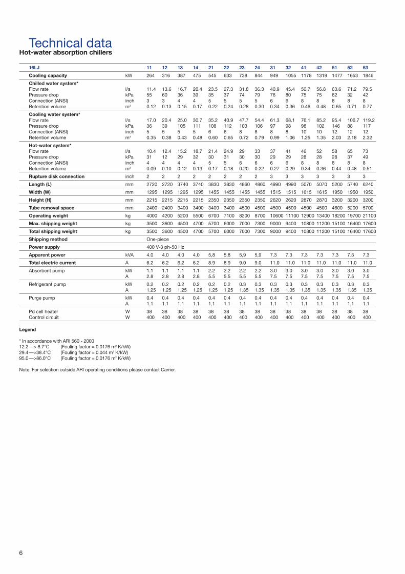
Technical dataHot-water absorption chillers
16LJ 11 12 13 14 21 22 23 24 31 32 41 42 51 52 53
Cooling capacity kW 264 316 387 475 545 633 738 844 949 1055 1178 1319 1477 1653 1846
Chilled water system*Flow rate l/s 11.4 13.6 16.7 20.4 23.5 27.3 31.8 36.3 40.9 45.4 50.7 56.8 63.6 71.2 79.5Pressure drop kPa 55 60 36 39 35 37 74 79 76 80 75 75 62 32 42Connection (ANSI) inch 3 3 4 4 5 5 5 5 6 6 8 8 8 8 8Retention volume m3 0.12 0.13 0.15 0.17 0.22 0.24 0.28 0.30 0.34 0.36 0.46 0.48 0.65 0.71 0.77
Cooling water system*Flow rate l/s 17.0 20.4 25.0 30.7 35.2 40.9 47.7 54.4 61.3 68.1 76.1 85.2 95.4 106.7 119.2Pressure drop kPa 36 39 105 111 108 112 103 106 97 98 98 102 146 88 117Connection (ANSI) inch 5 5 5 5 6 6 8 8 8 8 10 10 12 12 12Retention volume m3 0.35 0.38 0.43 0.48 0.60 0.65 0.72 0.79 0.99 1.06 1.25 1.35 2.03 2.18 2.32
Hot-water system*Flow rate l/s 10.4 12.4 15.2 18.7 21.4 24.9 29 33 37 41 46 52 58 65 73Pressure drop kPa 31 12 29 32 30 31 30 30 29 29 28 28 28 37 49Connection (ANSI) inch 4 4 4 4 5 5 6 6 6 6 8 8 8 8 8Retention volume m3 0.09 0.10 0.12 0.13 0.17 0.18 0.20 0.22 0.27 0.29 0.34 0.36 0.44 0.48 0.51
Rupture disk connection inch 2 2 2 2 2 2 2 2 3 3 3 3 3 3 3
Length (L) mm 2720 2720 3740 3740 3830 3830 4860 4860 4990 4990 5070 5070 5200 5740 6240
Width (W) mm 1295 1295 1295 1295 1455 1455 1455 1455 1515 1515 1615 1615 1950 1950 1950
Height (H) mm 2215 2215 2215 2215 2350 2350 2350 2350 2620 2620 2870 2870 3200 3200 3200
Tube removal space mm 2400 2400 3400 3400 3400 3400 4500 4500 4500 4500 4500 4500 4600 5200 5700
Operating weight kg 4000 4200 5200 5500 6700 7100 8200 8700 10600 11100 12900 13400 18200 19700 21100
Max. shipping weight kg 3500 3600 4500 4700 5700 6000 7000 7300 9000 9400 10800 11200 15100 16400 17600
Total shipping weight kg 3500 3600 4500 4700 5700 6000 7000 7300 9000 9400 10800 11200 15100 16400 17600
Shipping method One-piece
Power supply 400 V-3 ph-50 Hz
Apparent power kVA 4.0 4.0 4.0 4.0 5,8 5,8 5,9 5,9 7.3 7.3 7.3 7.3 7.3 7.3 7.3
Total electric current A 6.2 6.2 6.2 6.2 8.9 8.9 9.0 9.0 11.0 11.0 11.0 11.0 11.0 11.0 11.0
Absorbent pump kW 1.1 1.1 1.1 1.1 2.2 2.2 2.2 2.2 3.0 3.0 3.0 3.0 3.0 3.0 3.0A 2.8 2.8 2.8 2.8 5.5 5.5 5.5 5.5 7.5 7.5 7.5 7.5 7.5 7.5 7.5
Refrigerant pump kW 0.2 0.2 0.2 0.2 0.2 0.2 0.3 0.3 0.3 0.3 0.3 0.3 0.3 0.3 0.3A 1.25 1.25 1.25 1.25 1.25 1.25 1.35 1.35 1.35 1.35 1.35 1.35 1.35 1.35 1.35
Purge pump kW 0.4 0.4 0.4 0.4 0.4 0.4 0.4 0.4 0.4 0.4 0.4 0.4 0.4 0.4 0.4A 1.1 1.1 1.1 1.1 1.1 1.1 1.1 1.1 1.1 1.1 1.1 1.1 1.1 1.1 1.1
Pd cell heater W 38 38 38 38 38 38 38 38 38 38 38 38 38 38 38Control circuit W 400 400 400 400 400 400 400 400 400 400 400 400 400 400 400
Legend
* In accordance with ARI 560 - 200012.2—> 6.7°C (Fouling factor = 0.0176 m2 K/kW)29.4—>38.4°C (Fouling factor = 0.044 m2 K/kW)95.0—>86.0°C (Fouling factor = 0.0176 m2 K/kW)
Note: For selection outside ARI operating conditions please contact Carrier.
7
Scope of supply1. Standards met
The units comply with the following standards:• ARI 560-2000• 89/392/EEC (machine directive)• 73/23/EEC (low-voltage directive)• 89/336/EEC (electromagnetic compatibility directive)• 97/23/EC (pressure equipment directive)
2. Absorption chiller, comprising:1. Lower shell
• Evaporator and refrigerant dispersion tray• Absorber and absorbent dispersion tray• Eliminators• Bases
2. Upper shell• Generator• Condenser• Low temperature (LT) generator• Eliminators• Rupture disk mounting flange
3. Heat exchangers
4. Pumps• Absorbent pump with isolating valves• Refrigerant pump with isolating valves• Purge pump
5. Purge unit• Purge tank• Ejector and liquid trap• Piping and various manual valves• Palladium cell with heater
6. Control panel• Controller with data display
LEDs and operation buttons• Inverter for absorbent pump (option)• Circuit breaker• Transformer• Relays and terminal blocks• Purge pump operation switch
7. Locally mounted parts• Temperature sensors• Chilled-water flow switch• Generator pressure switch
8. Interconnecting piping and wiring• Refrigerant and absorbent piping• Internal power and control wiring
9. Initial charge• Absorbent (lithium bromide)• Refrigerant (water)• Inhibitor (lithium molybdate)
10. Painting• Main unit: Rust-preventive paint• Control panel: Finish paint
11. Accessories• Operation manual: One set• Washer (for fixing foundation bolts): One set• Gasket and sealant for rupture disk: One set
3. Factory test1. Check of external dimensions2. Hydraulic pressure test of water headers
Test pressure is 1.5 times of maximum working pressure3. Vacuum-side leak test4. Electric insulation resistance test5. Dielectric breakdown test6. Function test of electric circuit and safety devices
4. Scope of supply of the purchaser1. Building and foundations2. External chilled water, cooling water and hot water piping
work including various safety valves, isolation valves,mating flanges, gaskets, bolts and nuts, etc.
3. External wiring and piping for the chillers includingnecessary parts
4. Insulation for the chillers including necessary parts.5. Finish painting of the chillers (if needed)6. Cooling water entering temperature control device7. Cooling water treatment device8. Various temperature/pressure gauges for steam and water
lines.9. Cooling tower(s), chilled-water pump(s) and hot-water
three-way control valve10. Electric power supply (as specified)11. Supply of chilled water, cooling water, steam and air* at
rated conditions12. Maintenance of the chiller13. Necessary tools, labour and materials for installation and
site test operation14. Any other item not specifically mentioned in the scope of
supply
* If pneumatic hot-water valve control is used
8
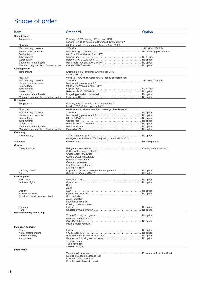
Scope of order
Item Standard OptionChilled water
Temperature Entering: 12.2ºC, leaving: 6ºC through 12ºCLeaving: 6.7ºC, temperature difference 3 K through 10 K
Flow rate 0.043 l/s x kW - Temperature difference (min. 50%)Max. working pressure 1034kPa . . . . . . . . . . . . . . . . . . . . . . . . . . . . . . . . . . . . . . . . . . . . . . . . . .1540 kPa, 2068 kPaHydraulic test pressure Max.working pressure x 1.5 . . . . . . . . . . . . . . . . . . . . . . . . . . . . . . . . . . . .Max working pressure x 1.5Fouling factor 0.018 m2 K/kW Max. 0.18 m2 K/kWTube material Copper tube . . . . . . . . . . . . . . . . . . . . . . . . . . . . . . . . . . . . . . . . . . . . . . . .Cu Ni tubeWater quality Refer to JRA-GL02E-1994 . . . . . . . . . . . . . . . . . . . . . . . . . . . . . . . . . . . . .No optionStructure of water header Removable type and epoxy treated . . . . . . . . . . . . . . . . . . . . . . . . . . . . . .No optionManufacturing standard of water header Carrier-SANYO standard . . . . . . . . . . . . . . . . . . . . . . . . . . . . . . . . . . . . . .No option
Cooling waterTemperature Entering: 29.4ºC, entering: 20ºC through 33ºC
Leaving: 38.4ºCFlow rate 0.065 l/s x kW, within water flow rate range of each modelMax. working pressure 1034kPa . . . . . . . . . . . . . . . . . . . . . . . . . . . . . . . . . . . . . . . . . . . . . . . . . .1540 kPa, 2068 kPaHydraulic test pressure Max. working pressure x 1.5Fouling factor 0.044m2 K/kW Max. 0.18m2 K/kWTube material Copper tube . . . . . . . . . . . . . . . . . . . . . . . . . . . . . . . . . . . . . . . . . . . . . . . .Cu Ni tubeWater quality Refer to JRA-GL02E-1994 . . . . . . . . . . . . . . . . . . . . . . . . . . . . . . . . . . . . .No optionStructure of water header Hinged type and epoxy treated . . . . . . . . . . . . . . . . . . . . . . . . . . . . . . . . .No optionManufacturing standard of water header Flanges ANSI . . . . . . . . . . . . . . . . . . . . . . . . . . . . . . . . . . . . . . . . . . . . . . .No option
Hot waterTemperature Entering: 95.0ºC, entering: 80ºC through 98ºC
Leaving: 86.0ºC, leaving: min. 75ºCFlow rate 0.039 l/s x kW, within water flow rate range of each modelMax. working pressure 1034kPa . . . . . . . . . . . . . . . . . . . . . . . . . . . . . . . . . . . . . . . . . . . . . . . . . .No optionHydraulic test pressure Max. working pressure x 1.5 . . . . . . . . . . . . . . . . . . . . . . . . . . . . . . . . . . .No optionFouling factor 0.018m2 K/kW . . . . . . . . . . . . . . . . . . . . . . . . . . . . . . . . . . . . . . . . . . . . . .No optionTube material Copper tube . . . . . . . . . . . . . . . . . . . . . . . . . . . . . . . . . . . . . . . . . . . . . . . .No optionWater quality Refer to JRA-GL02E-1994 . . . . . . . . . . . . . . . . . . . . . . . . . . . . . . . . . . . . .No optionStructure of water header Removable type . . . . . . . . . . . . . . . . . . . . . . . . . . . . . . . . . . . . . . . . . . . . .No optionManufacturing standard of water header Flanged ANSI . . . . . . . . . . . . . . . . . . . . . . . . . . . . . . . . . . . . . . . . . . . . . . .No option
ElectricityPower supply 400V - 3 phase - 50Hz . . . . . . . . . . . . . . . . . . . . . . . . . . . . . . . . . . . . . . .No option
(Voltage control within ±10%, frequency control within ±5%)Shipment One section . . . . . . . . . . . . . . . . . . . . . . . . . . . . . . . . . . . . . . . . . . . . . . . .Multi-shipment
ControlSafety functions Refrigerant temperature . . . . . . . . . . . . . . . . . . . . . . . . . . . . . . . . . . . . . . .Cooling water flow switch
Chilled water freeze protectionChilled water flow switchCooling water temperatureGenerator temperature Generator pressureCrystallization protectionMotor protection
Capacity control Digital PID control by chilled-water temperature . . . . . . . . . . . . . . . . . . . .No optionParts Selected by Carrier-SANYO . . . . . . . . . . . . . . . . . . . . . . . . . . . . . . . . . . . .No option
Control panelPaint finish Munsell 5Y-7/1 . . . . . . . . . . . . . . . . . . . . . . . . . . . . . . . . . . . . . . . . . . . . . .No optionIndication lights Operation . . . . . . . . . . . . . . . . . . . . . . . . . . . . . . . . . . . . . . . . . . . . . . . . . .No option
StopAlarm
Display LED . . . . . . . . . . . . . . . . . . . . . . . . . . . . . . . . . . . . . . . . . . . . . . . . . . . . . .No optionExternal terminals Operation indication . . . . . . . . . . . . . . . . . . . . . . . . . . . . . . . . . . . . . . . . . .No option(volt-free normally open contact) Stop indication
Alarm indicationFeedback indicationCooling mode indication
Structure Indoor type . . . . . . . . . . . . . . . . . . . . . . . . . . . . . . . . . . . . . . . . . . . . . . . . .No optionParts Selected by Carrier-SANYO . . . . . . . . . . . . . . . . . . . . . . . . . . . . . . . . . . . .No option
Electrical wiring and pipingWire: 600 V polyvinyl grade . . . . . . . . . . . . . . . . . . . . . . . . . . . . . . . . . . .No optionchloride-insulated wiresPipe: Plicatube . . . . . . . . . . . . . . . . . . . . . . . . . . . . . . . . . . . . . . . . . . . . . .No option(flexible metal conduits)
Insulation conditionPlace Indoor . . . . . . . . . . . . . . . . . . . . . . . . . . . . . . . . . . . . . . . . . . . . . . . . . . . . .No optionAmbient temperature 5oC through 40oC . . . . . . . . . . . . . . . . . . . . . . . . . . . . . . . . . . . . . . . . . . . .No optionAmbient humidity Relative humidity: max. 90% at 45oC . . . . . . . . . . . . . . . . . . . . . . . . . . . .No optionAtmosphere Be sure the following are not present . . . . . . . . . . . . . . . . . . . . . . . . . . . .No option
- Corrosive gas- Explosive gas- Poisonous gas
Factory testVacuum-side leak test . . . . . . . . . . . . . . . . . . . . . . . . . . . . . . . . . . . . . . . .Performance test at full loadElectric insulation resistance testDielectric breakdown testFunction test of electric circuit
9
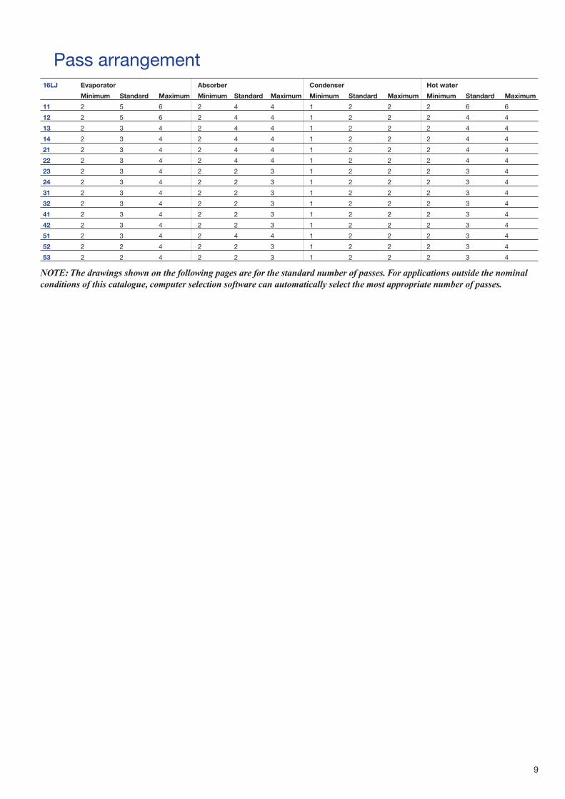
Pass arrangement16LJ Evaporator Absorber Condenser Hot water
Minimum Standard Maximum Minimum Standard Maximum Minimum Standard Maximum Minimum Standard Maximum
11 2 5 6 2 4 4 1 2 2 2 6 6
12 2 5 6 2 4 4 1 2 2 2 4 4
13 2 3 4 2 4 4 1 2 2 2 4 4
14 2 3 4 2 4 4 1 2 2 2 4 4
21 2 3 4 2 4 4 1 2 2 2 4 4
22 2 3 4 2 4 4 1 2 2 2 4 4
23 2 3 4 2 2 3 1 2 2 2 3 4
24 2 3 4 2 2 3 1 2 2 2 3 4
31 2 3 4 2 2 3 1 2 2 2 3 4
32 2 3 4 2 2 3 1 2 2 2 3 4
41 2 3 4 2 2 3 1 2 2 2 3 4
42 2 3 4 2 2 3 1 2 2 2 3 4
51 2 3 4 2 4 4 1 2 2 2 3 4
52 2 2 4 2 2 3 1 2 2 2 3 4
53 2 2 4 2 2 3 1 2 2 2 3 4
NOTE: The drawings shown on the following pages are for the standard number of passes. For applications outside the nominalconditions of this catalogue, computer selection software can automatically select the most appropriate number of passes.
10
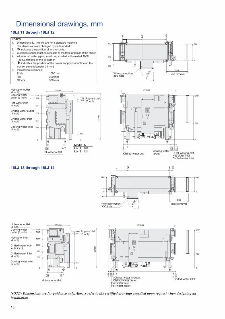
Dimensional drawings, mm16LJ 11 through 16LJ 12
NOTE: Dimensions are for guidance only.Always refer to the certified drawings supplied upon request when designing aninstallation.
3267
311646
835
3
180
5802
587
PMUP EGRUPEGRUP
200 0
0
071
310
562
745
0043
087
291
008
0
0
0
910
126
882
0
0
0
)L(0473
1161
00914812
2215
(H)
003
52125991
3621
329
595
)W(5921
006 R
16LJ 13 through 16LJ 14
Hot-water outlet(4 inch)Cooling water outlet (5 inch)
Hot-water inlet(4 inch)
Chilled-water outlet(3 inch)
Chilled-water inlet(3 inch)
Cooling water inlet(5 inch)
Rupture disk(2 inch)
Hot-water outletChilled-water out
Cooling waterin/out Hot-water outlet
Hot-water inletChilled-water inlet
Wire connection35Ø hole
Tube removal
Hot-water outlet(4 inch)Cooling water outlet (5 inch)
Hot-water inlet(4 inch)
Chilled-water out-let (4 inch)
Chilled-water inlet(4 inch)
Cooling water inlet(5 inch)
Rupture disk(2 inch)
Hot-water outletChilled-water in/outlet
Chilled-water outletHot-water inletHot-water outlet
Chilled-water inlet
Wire connection35Ø hole
Tube removal
Model ALJ-11 101LJ-12 124
NOTES1. Dimensions (L), (W), (H) are for a standard machine.
The dimensions are changed by parts added. 2. indicates the position of anchor bolts.3. Clearance space must be available at the front and rear of the chiller.4. All external water piping must be provided with welded ANSI
150 LB flanges by the customer.5. indicates the position of the power supply connection on the
control panel (diameter 35 mm)6. Installation clearance:
Ends 1000 mmTop 200 mmOthers 500 mm
11
4 28
2 50
5522
538
220
0
0
0054
4271
6431
6001
59225312
506
0
1090
1065 270
1 90
0091
9132
003
)W(5541
0
0
2350
(H)
)L(0684
4123
4096
542
3886
1170
0
006 R
220
6290001
0
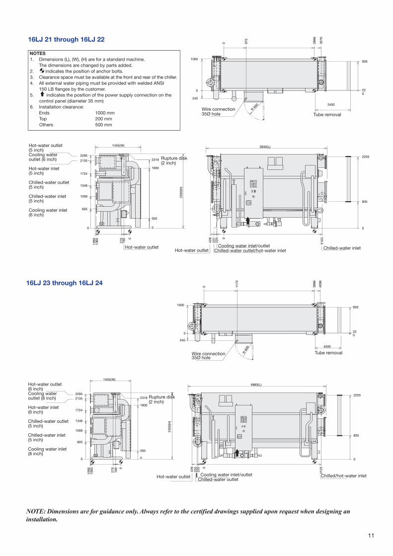
16LJ 23 through 16LJ 24
16LJ 21 through 16LJ 22
237
)L(0383
310342
8
220
5522
538
PMUP EGRUPEGRUP
0
0
3076
542
2866
970
0
006 R
22
6290001
00
0
0043
4271
1090
1065 27
019
0
0091
9132
2350
(H)
003
)W(5541
5922
5312
6431
6001
506
0
0
NOTE: Dimensions are for guidance only.Always refer to the certified drawings supplied upon request when designing aninstallation.
Hot-water outlet(5 inch)Cooling wateroutlet (6 inch)
Hot-water inlet(5 inch)
Chilled-water outlet(5 inch)
Chilled-water inlet(5 inch)
Cooling water inlet(6 inch)
Rupture disk(2 inch)
Hot-water outletHot-water outlet
Cooling water inlet/outletChilled-water outlet/hot-water inlet Chilled-water inlet
Wire connection35Ø hole Tube removal
Hot-water outlet(6 inch)Cooling wateroutlet (8 inch)
Hot-water inlet(6 inch)
Chilled-water outlet(5 inch)
Chilled-water inlet(5 inch)
Cooling water inlet(8 inch)
Rupture disk(2 inch)
Hot-water outlet Cooling water inlet/outletChilled-water outlet
Chilled/hot-water inlet
Wire connection35Ø hole
Tube removal
NOTES1. Dimensions (L), (W), (H) are for a standard machine.
The dimensions are changed by parts added. 2. indicates the position of anchor bolts.3. Clearance space must be available at the front and rear of the chiller.4. All external water piping must be provided with welded ANSI
150 LB flanges by the customer.5. indicates the position of the power supply connection on the
control panel (diameter 35 mm)6. Installation clearance:
Ends 1000 mmTop 200 mmOthers 500 mm
12
16LJ 31 through 16LJ 32
16LJ 41 through 16LJ 42
NOTE: Dimensions are for guidance only.Always refer to the certified drawings supplied upon request when designing aninstallation.
Hot-water outlet(6 inch)Cooling water outlet (8 inch)
Hot-water inlet(6 inch)Chilled-water outlet(6 inch)
Chilled-water inlet(6 inch)
Cooling water inlet(8 inch)
Rupture disk(3 inch)
Hot-water outletCooling water outlet
Chilled-water outletChilled-water inletHot-water inlet
Cooling water inletHot-water outlet
Wire connection35Ø hole
Tube removal
Hot-water outlet(8 inch)Cooling water out-let (10 inch)
Hot-water inlet(8 inch)
Chilled-water outlet(8 inch)
Chilled-water inlet(8 inch)
Cooling water inlet(10 inch)
Rupture disk(3 inch)
Hot-water outlet Hot-water inletChilled-water inlet
Cooling water inlet/outletChilled-water outlet
Hot-water outlet
Wire connection35Ø hole
Tube removal
NOTES1. Dimensions (L), (W), (H) are for a standard machine.
The dimensions are changed by parts added. 2. indicates the position of anchor bolts.3. Clearance space must be available at the front and rear of the chiller.4. All external water piping must be provided with welded ANSI
150 LB flanges by the customer.5. indicates the position of the power supply connection on the
control panel (diameter 35 mm)6. Installation clearance:
Ends 1000 mmTop 200 mmOthers 500 mm
13
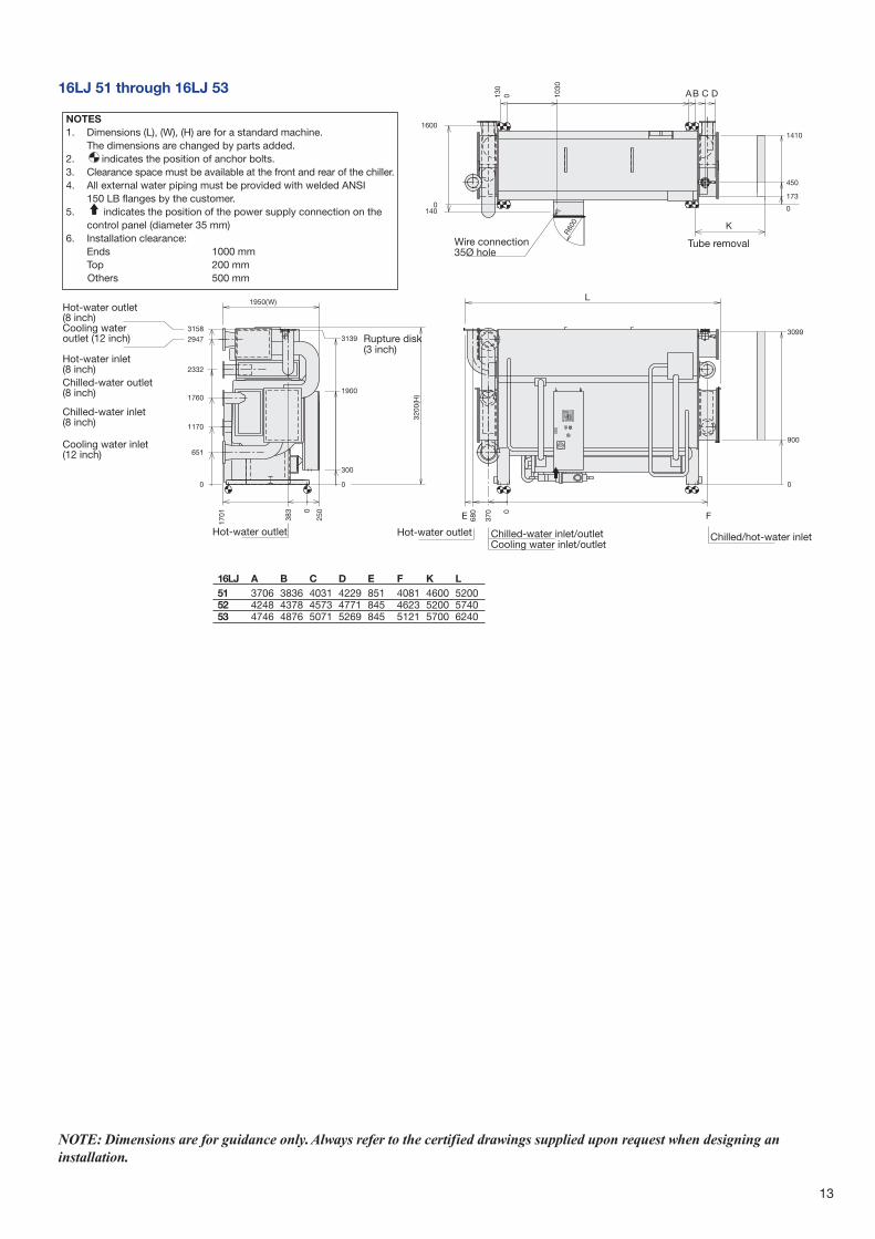
16LJ 51 through 16LJ 53
Hot-water outlet(8 inch)Cooling water outlet (12 inch)
Hot-water inlet(8 inch)Chilled-water outlet(8 inch)
Chilled-water inlet(8 inch)
Cooling water inlet(12 inch)
Rupture disk(3 inch)
Hot-water outlet Chilled/hot-water inletChilled-water inlet/outletCooling water inlet/outlet
Hot-water outlet
Wire connection35Ø hole
Tube removal
16LJ A B C D E F K L51 3706 3836 4031 4229 851 4081 4600 520052 4248 4378 4573 4771 845 4623 5200 574053 4746 4876 5071 5269 845 5121 5700 6240
NOTE: Dimensions are for guidance only.Always refer to the certified drawings supplied upon request when designing aninstallation.
NOTES1. Dimensions (L), (W), (H) are for a standard machine.
The dimensions are changed by parts added. 2. indicates the position of anchor bolts.3. Clearance space must be available at the front and rear of the chiller.4. All external water piping must be provided with welded ANSI
150 LB flanges by the customer.5. indicates the position of the power supply connection on the
control panel (diameter 35 mm)6. Installation clearance:
Ends 1000 mmTop 200 mmOthers 500 mm
14
Foundation dimensions, mm
NOTES:1. The machine base has ø50-mm hole for the anchor bolt.2. The anchor bolt should be fixed as shown in the detail
drawing.Washer should be welded to the base (see Fig. 4)3. There should be a drain channel around the foundation.
4. The floor surface should be made waterproof to facilitatemaintenance work.
5. The surface of the foundation should be made flat.6. Anchor bolts and nuts are to be supplied by customer.
Figure 4 - Details of weld
Figure 3 - LJ 11 to LJ 42 Figure 5 - LJ 51 to LJ 53
Nut
WeldWasher
Base
A = 150 mm and more
Table 1 - Dimensional data
16LJ Weight, kg Dimensions. mmAA + BB AA BB A B C D E F G J K
11 4000 2000 2000 1896 185 100 360 800 150 1100 160 900
12 4200 2100 2100 1896 185 100 360 800 150 1100 160 900
13 5200 2600 2600 2916 185 100 360 800 150 1100 160 900
14 5500 2750 2750 2916 185 100 360 800 150 1100 160 900
21 6700 3350 3350 2866 200 100 400 1000 150 1300 200 1100
22 7100 3550 3550 2866 200 100 400 1000 150 1300 200 1100
23 8200 4100 4100 3886 200 100 400 1000 150 1300 200 1100
24 8700 4350 4350 3886 200 100 400 1000 150 1300 200 1100
31 10600 5300 5300 3836 225 250 450 1100 150 1400 100 1200
32 11100 5550 5550 3836 225 100 450 1100 150 1400 250 1200
41 12900 6450 6450 3836 225 100 450 1150 150 1450 250 1250
42 13400 6700 6700 3836 225 100 450 1150 150 1450 250 1250
51 18200 9100 9100 3706 130 190 510 1600 180 1960 250 1700
52 19700 9850 9850 4248 130 190 510 1600 180 1960 250 1700
53 21100 10550 10550 4746 130 190 510 1600 180 1960 250 1700
15
Control panel dimensions, mm
Remote control Ø27Hot-water control valveØ21 (LJ-01 through LJ 12)Ø27 (LJ-13 through LJ 24) Ø21 (LJ-31 through LJ 53)
Power supply Ø33
16
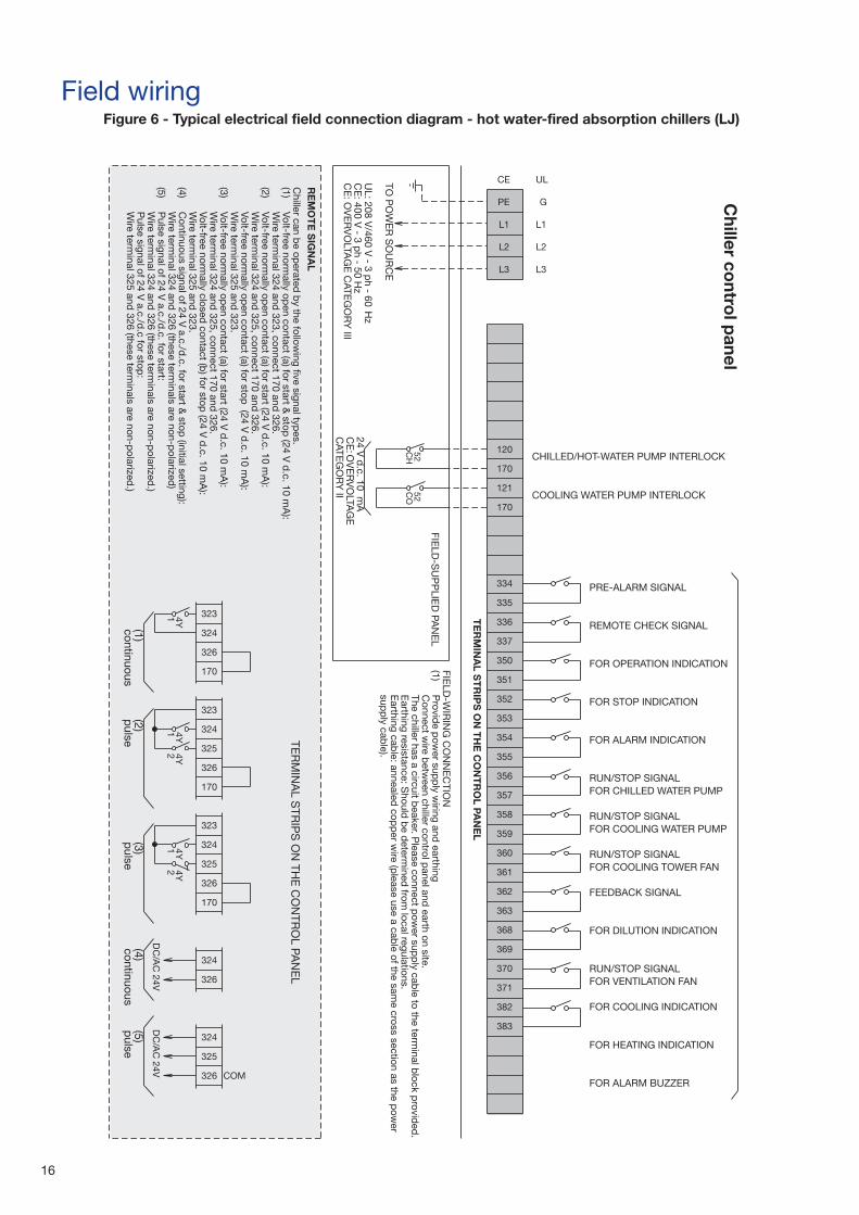
Field wiringFigure 6 - Typical electrical field connection diagram - hot water-fired absorption chillers (LJ)
Chiller co
ntrol p
anel
TE
RM
INA
LS
TR
IPS
ON
TH
EC
ON
TR
OL
PAN
EL
PRE-ALARM SIGNAL
REMOTE CHECK SIGNAL
FOR OPERATION INDICATION
FOR STOP INDICATION
FOR ALARM INDICATION
RUN/STOP SIGNALFOR CHILLED WATER PUMP
RUN/STOP SIGNALFOR COOLING WATER PUMP
RUN/STOP SIGNALFOR COOLING TOWER FAN
FEEDBACK SIGNAL
FOR DILUTION INDICATION
RUN/STOP SIGNALFOR VENTILATION FAN
FOR COOLING INDICATION
FOR HEATING INDICATION
FOR ALARM BUZZER
CHILLED/HOT-WATER PUMP INTERLOCK
COOLING WATER PUMP INTERLOCK
RE
MO
TE
SIG
NA
LC
hiller can be op
erated b
y the following five signal typ
es.(1)
Volt-free normally op
en contact (a) for start & stop
(24 V d
.c. 10 mA
):W
ire terminal 324 and
323, connect 170 and 326.
(2)Volt-free norm
ally open contact (a) for start (24 V
d.c. 10 m
A):
Wire term
inal 324 and 325, connect 170 and
326.Volt-free norm
ally open contact (a) for stop
(24 V d
.c. 10 mA
):W
ire terminal 325 and
323.(3)
Volt-free normally op
en contact (a) for start (24 V d
.c. 10 mA
):W
ire terminal 324 and
325, connect 170 and 326.
Volt-free normally closed
contact (b) for stop
(24 V d
.c. 10 mA
):W
ire terminal 325 and
323.(4)
Continuous signal of 24 V
a.c./d.c. for start &
stop (initial setting):
Wire term
inal 324 and 326 (these term
inals are non-polarized
)(5)
Pulse signal of 24 V
a.c./d.c. for start:
Wire term
inal 324 and 326 (these term
inals are non-polarized
.)P
ulse signal of 24 V a.c./d
.c for stop:
Wire term
inal 325 and 326 (these term
inals are non-polarized
.)
TO P
OW
ER
SO
UR
CE
UL:208 V
/460 V - 3 p
h - 60 Hz
CE
: 400 V - 3 p
h - 50H
zC
E: O
VE
RV
OLTA
GE
CATE
GO
RY
III24 V
d.c. 10 m
AC
E:O
VE
RV
OLTA
GE
CATE
GO
RY
II
FIELD
-SU
PP
LIED
PAN
EL
(1)(2)
(3)(4)
(5)continuous
pulse
pulse
continuousp
ulse
FIELD
-WIR
ING
CO
NN
EC
TION
(1)P
rovide p
ower sup
ply w
iring and earthing
Connect w
ire betw
een chiller control panel and
earth on site.The chiller has a circuit b
eaker. Please connect p
ower sup
ply cab
le to the terminal b
lock provid
ed.
Earthing resistance: S
hould b
e determ
ined from
local regulations.E
arthing cable: annealed
copp
er wire (p
lease use a cable of the sam
e cross section as the pow
ersup
ply cab
le).
TER
MIN
AL
STR
IPS
ON
THE
CO
NTR
OL
PAN
EL
17
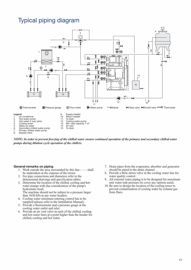
General remarks on piping1. Work outside the area surrounded by this line - - - - shall
be undertaken at the expense of the owner.2. For pipe connections and diameters refer to the
dimensional drawings and specification tables.3. Determine the location of the chilled, cooling and hot-
water pumps with due consideration of the pump’shydrostatic head.The machine should not be subject to a pressure largerthan 1030 kPa at any water headers.
4. Cooling water minimum entering control has to besupplied (please refer to the Installation Manual).
5. Provide a thermometer and a pressure gauge at thecooling water outlet and inlet.
6. Provide an air vent valve in each of the chilled, coolingand hot-water lines at a point higher than the header forchilled, cooling and hot water.
7. Drain pipes from the evaporator, absorber and generatorshould be piped to the drain channel.
8. Provide a blow-down valve in the cooling water line forwater quality control.
9. All external water piping is to be designed for maximumunit water-side pressure (to cover any options used).
10. Be sure to design the location of the cooling tower toprevent contamination of cooling water by exhaust gasfrom flues.
Typical piping diagram
NOTE: In order to prevent freezing of the chilled water ensure continued operation of the primary and secondary chilled-waterpumps during dilution cycle operation of the chillers.
T P FThermometer Pressure gauge Flow meter Water pump Strainer Stop valve Shutoff valve Thermostat
Legend1. Air conditioner2. Hot-water pump3. Hot-water 3-way valve4. Cooling tower5. Make-up water6. Secondary chilled-water pump7. Primary chilled-water pump8. Bypass valve
9. Supply header10. Return header11. To drain12. Cooling water pump13. Min. tank capacity 1 m3
14. Air vent15. To drain
Before operating the unit■ Before operating the unit be sure to read the operation manual
carefully.■ Installation should conform to all applicable local codes and
regulations.
During the installation■ Read the installation manual carefully before offloading and
installing the unit.■ All work must be carried out be qualified personnel to
prevent injuries and damage to the equipment.■ Waterproof the unit foundation and provide a drain channel to
prevent water damage to the surrounding equipment.■ Provide adequate space around the unit for maintenance work
to ensure safe working conditions.
Maintenance■ In addition to daily inspection periodical maintenance is
required. Insufficient or incorrect maintenance may causefire, electric shock and injuries.
■ Please consult your local service office for further guidance.
Avoiding hazardous places■ Keep the units away from dangerous inflammable substances
such as gasoline, thinner and combustible gases, as these mayresult in a fire.
Safety considerations
18


Order No. 11615-20, 11.2005. Supersedes: New. Manufacturer: Carrier-Sanyo, Dalian, PR China.Manufacturer reserves the right to change any product specifications without notice. Printed on Totally Chlorine Free Paper.
Printed in the Netherlands.
GB/T-24001 to ISO14001:1996