Embed Size (px)
Citation preview
Sub
ject
to
mod
ifica
tions
User ManualOperation Instructions
2.1EN-38033-H12
Single-Line Pump 603 S with Control Unit
B-P603S-000a09
810-53021-1H
SKF Lubrication Systems Germany GmbH ● Heinrich Hertz-Str. 2-8 D-69190 Walldorf Tel. +49(0) 6227 33-0 ● Fax: +49 (0) 6227 33-259
2.1EN-38033-H12
Pag 2 f 52
User ManualOperation Instructions
Sub
ject
to
mod
ifica
tions
SKF Lubrication Systems Germany GmbH ● Heinrich Hertz-Str. 2-8 D-69190 Walldorf Tel. +49(0) 6227 33-0 ● Fax: +49 (0) 6227 33-259

2.1EN-38033-H12
Sub
ject
to
mod
ifica
tions
User ManualOperation Instructions
P 3 f 52
Table of Contents
Page
Introduction Explanation of Symbols Used ............................................ 4 User’s Responsibility ......................................................... 4 Environmental Protection .................................................. 4 Service .............................................................................. 4 Safety Instructions Appropriate Use ................................................................ 5 Misuse ............................................................................... 5 Exclusion of Liability .................................................... 5 Regulation for Prevention of Accidents ............................. 5 General Safety Instructions ............................................... 5 Operation, Maintenance und Repair ................................... 5 Repair .......................................................................... 5 Operation / Maintenance .............................................. 5 Disposal ........................................................................ 5 Installation ......................................................................... 6
Assembly and Maintenance of the Hydraulic Hoses .... 6 Description Pump 603 S ....................................................................... 7 Reservoir sizes .................................................................. 7 Electrical connection ......................................................... 7 Low-level control (optional) ................................................ 7 Identification Code .......................................................... 8 Decoding: Electric connecting possibilities ...................... 43 For further information refer to: Maintenance Instructions 2.0-38009
“Priming with Follower Plate“ Technical Description
P603S-8/15XLF-3Z7-AC-2A7.16-S17 2.0-30019
P603 Parts Catalogue 2.0-20005 List of Lubricants 2.0-40001
Page
Mode of Operation Functional Description ....................................................... 9 Drive ............................................................................. 9 Pressurization ............................................................... 9 Pressure safety ............................................................ 9 - Internal pressure sensor or switch ............................. 9 - Internal and external pressure sensors or switches ... 9 Pressure relief ............................................................ 10 Pump elements with fixed lubricant output ....................... 11 Low-level control .............................................................. 12 Membrane Keypad ........................................................... 13 Display of the membrane keypad ..................................... 13 Operating mode .......................................................... 13 Low-level control ........................................................ 13 Malfunctions ............................................................... 14 Flowcharts .................................................................. 15 Multifunctional Pushbutton ............................................... 19 Triggering an additional operating cycle externally ..... 19 Function display ......................................................... 19 Adjustment of lubricant volume ± 25 % ...................... 19 Setting and Operation Factory Settings ............................................................... 20 Operator Keys .................................................................. 20 Display mode ................................................................... 21 Programming mode ......................................................... 23 Operating mode ............................................................... 29 Triggering an additional operating cycle ..................... 29 Maintenance and Repair Maintenance .................................................................... 31 To fill reservoir ............................................................ 31 Reservoir with follower plate ...................................... 32 Repair .............................................................................. 32 Electrical Connection ....................................................... 33 Tests ................................................................................ 34 Troubleshooting ............................................................. 35 Technical Data Rating .............................................................................. 36 Tightening Torques .......................................................... 36 Settings ............................................................................ 36 Electrical Data .................................................................. 37 Connection Diagrams DC ................................................ 38 Connection Diagrams AC ................................................ 40 Schematic of Single line Pump 603 S .............................. 43 Dimensions ...................................................................... 44 Drilling Template ........................................................ 46 Jumper Configuration ................................................... 47 Appendix Data sheet of the internal pressure switches ................... 48 Data sheet of the internal pressure transducer ................ 49 EC Declaration of Conformity ....................................... 51
SKF Lubrication Systems Germany GmbH ● Heinrich Hertz-Str. 2-8 D-69190 Walldorf Tel. +49(0) 6227 33-0 ● Fax: +49 (0) 6227 33-259

2.1EN-38033-H12
Pag 4 f 52
User ManualOperation Instructions
Sub
ject
to
mod
ifica
tions
Introduction
Explanation of Symbols Used
The following description standards are used in this manual: Safety Instructions
Structure of safety instructions: Pictogram Signal word Danger text
- Danger note - How to avoid danger
The following pictograms are used in this manual and are combined with the corresponding signal words:
1013A94
4273a00
6001a02
- ATTENTION - CAUTION - WARNING
- ATTENTION - CAUTION - WARNING
- NOTE - IMPORTANT
The signal words give the seriousness of danger if the follow-ing text is not observed: ATTENTION refers to faults or damages on
machines. CAUTION refers to bad damages and possi-
ble injuries. WARNING refers to possible dangerous inju-
ries. NOTE indicates improved operation of the
device. IMPORTANT indicates special operating fea-
tures of the device. Example:
1013A94
ATTENTION!
When making use of other than the tested spare parts, serious damage may affect your device.
Furthermore, you will find the following text symbols in this manual: Listing of applicable statements
- Subpoint of applicable statements 1. Determination of the number or sequence of contents Procedural instruction
User's Responsibility
To ensure the safe operation of the unit, the user is responsi-ble for the following: 1. The pump / system shall be operated only for the intend-
ed use (see next chapter "Safety Instructions") and its design shall neither be modified nor transformed.
2. The pump / system shall be operated only if it is in a proper functioning condition and if it is operated in ac-cordance with the maintenance requirements.
3. The operating personnel must be familiar with this User Manual and the safety instructions mentioned within and observe these carefully.
The correct installation and connection of tubes and hoses, if not specified by SKF, is the user's responsibility. SKFwill gladly assist you with any questions per-taining to the installation.
Environmental Protection
Waste (e.g. used oil, detergents, lubricants) must be dis-posed of in accordance with relevant environmental regula-tions.
Service
The personnel responsible for the handling of the pump / system must be suitably qualified. If required, SKF offers you full service in the form of advice, on-site installation assistance, training, etc. We will be pleased to inform you about our possibilities to support you purposefully. In the event of inquiries pertaining to maintenance, repairs and spare parts, we require model specific data to enable us to clearly identify the components of your pump / system. Therefore, always indicate the part, model and series number of your pump / system.
SKF Lubrication Systems Germany GmbH ● Heinrich Hertz-Str. 2-8 D-69190 Walldorf Tel. +49(0) 6227 33-0 ● Fax: +49 (0) 6227 33-259
2.1EN-38033-H12
Sub
ject
to
mod
ifica
tions
User ManualOperation Instructions
P 5 f 52
1013A94
CAUTION!
It is not allowed to use the pump in poten-tially explosive fields.
Pack defective p.c.b.s properly and send it back to the factory.
4273a00
WARNING! Before maintenance or repair of pumps switch off their power supply.
Repair
Repairs should only be performed by authorized personnel who are familiar with the repair instructions.
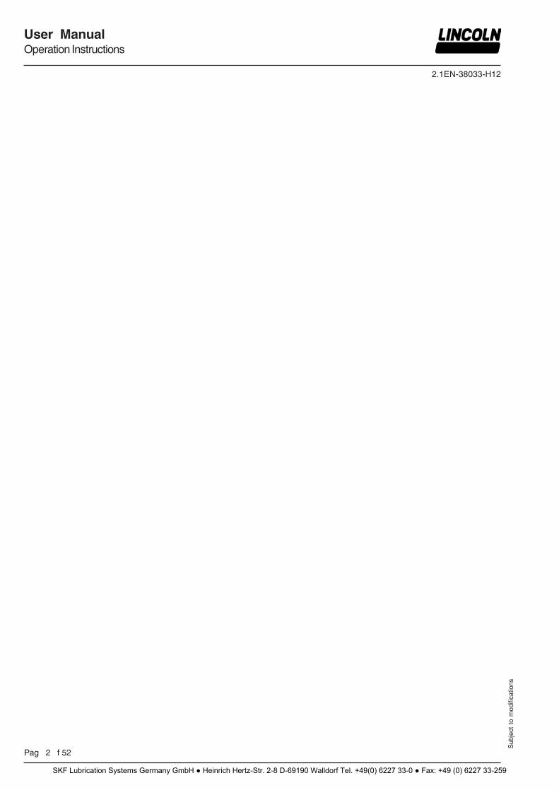
Appropriate Use
The single-line pump 603 S (S = Single) has been designed for automatic lubrication of commercial vehicles, construction machines, agricultural devices, wind power plants as well as for applications in the general industry. The 603 S pump has been designed for intermittent operation and is not suitable for continuous operation. It can be operat-ed only in combination with single-line metering devices (e.g. QSL). The system is able to supply lubricants up to NLGI grade 2 (see List of Lubricants 2.0-40001-A06).
Misuse
Any use of the 603 S pump that is not expressly mentioned in this User Manual will be regarded as misuse. If the 603 S pump is used or operated in a different manner other than specified, any claim for warranty or liability will be null and void.
6001a02
NOTE
If personal injury or material damage occurs as a result of inappropriate opera-tion, e.g. if the safety instructions are ignored or resulting from an incorrect installation of the 603 S pump, no claims or legal actions may be taken against SKF..
Exclusion of Liability
The manufacturer of the 603 S pump will not accept any liability for damages caused by: a lack of lubricant due to an irregular refilling of the pump the use of contaminated lubricants the use of greases which are not or only conditionally
pumpable in the 603 S pump inadequate disposal of used or contaminated lubricants as
well as of components that have been in touch with lubri-cant
unauthorized modification of the system components the use of unapproved parts an operation without adhering to the minimum pause time
an respectively the maximum lubrication time (see chapter “Technical Data“)
Operation, Maintenance and Repair
1013A94
ATTENTION!
Before carrying out any maintenance or repair works on the 603 S pump, make sure that the pressure lines towards the single-line metering devices are depressur-ized.
1013a94
CAUTION!
… with reservoir and follower plate:
Inside the reservoir, the reservoir cover is still under spring tension to feed the fol-lower plate back. When removing the reservoir cover avoid any sudden spring release. Wear protective glasses.
Operation/Maintenance
Pumps 603 S must be operated with a pressure relief valve 1) installed. must be refilled in regular intervals with clean lubricant
recommended by the manufacturer without air entrap-ments.
operate automatically. However, a regular check (approx. every 2 days) should be made to ensure that lubricant is emerging from all lubrication points.
1) to be ordered separately
Regulations for Prevention of Accidents
To prevent accidents, observe all city, state and federal safety regulations of the country in which the product will be used.
Avoid the operation with - unapproved parts. - insufficient or contaminated lubricants.
Disposal
Dispose of used or contaminated lubricants as well as of parts that were in touch with lubricant according to the legal regula-tions pertaining to environmental protection. Make sure to observe the safety data sheets of the lubricants used.
General Safety Instructions
Lincoln Quicklub centralized lubrication systems - are designed state-of-the-art. - can be assembled for safe operation
Incorrect use may result in bearing damage caused by poor or over-lubrication.
Unauthorized modifications or changes to an installed system are not admissible. Any modification must be subject to prior consultation with the manufacturer of the lubrication system.
Safety Instructions
SKF Lubrication Systems Germany GmbH ● Heinrich Hertz-Str. 2-8 D-69190 Walldorf Tel. +49(0) 6227 33-0 ● Fax: +49 (0) 6227 33-259
2.1EN-38033-H12
Pag 6 f 52
User ManualOperation Instructions
Sub
ject
to
mod
ifica
tions
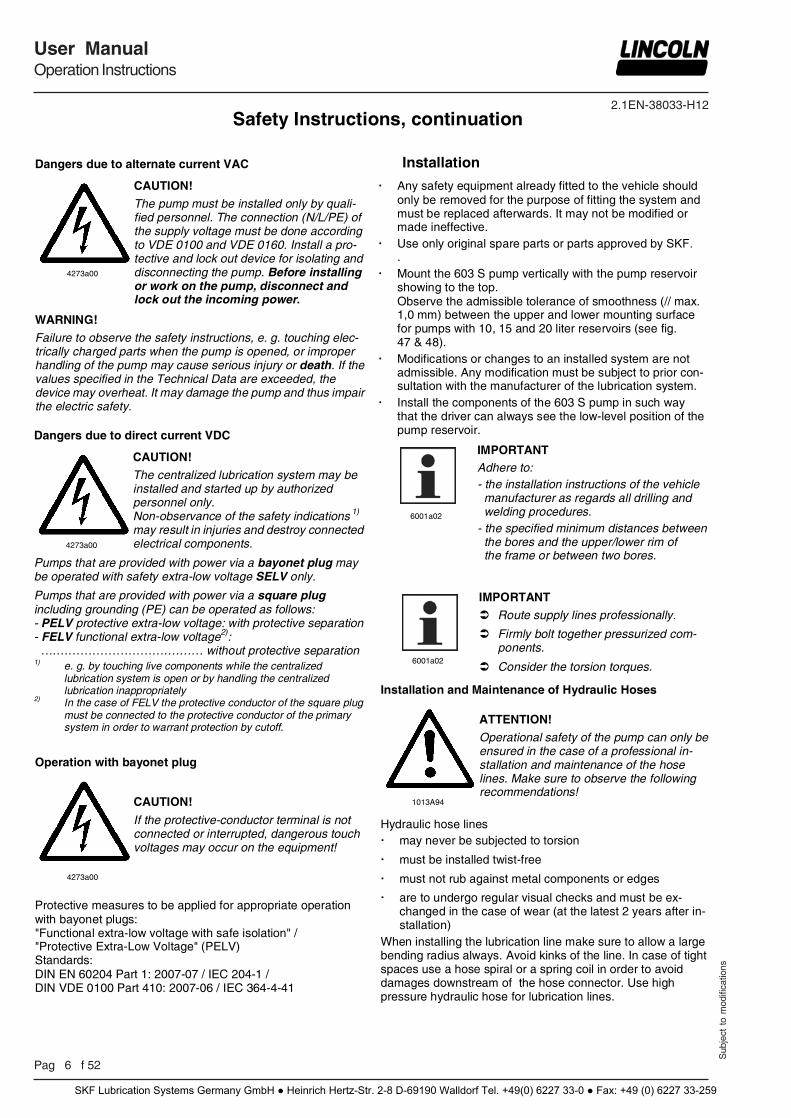
Dangers due to alternate current VAC
4273a00
CAUTION!
The pump must be installed only by quali-fied personnel. The connection (N/L/PE) of the supply voltage must be done according to VDE 0100 and VDE 0160. Install a pro-tective and lock out device for isolating and disconnecting the pump. Before installing or work on the pump, disconnect and lock out the incoming power.
WARNING!
Failure to observe the safety instructions, e. g. touching elec-trically charged parts when the pump is opened, or improper handling of the pump may cause serious injury or death. If the values specified in the Technical Data are exceeded, the device may overheat. It may damage the pump and thus impair the electric safety.
Installation
Any safety equipment already fitted to the vehicle should only be removed for the purpose of fitting the system and must be replaced afterwards. It may not be modified or made ineffective.
Use only original spare parts or parts approved by SKF..
Mount the 603 S pump vertically with the pump reservoir showing to the top. Observe the admissible tolerance of smoothness (// max. 1,0 mm) between the upper and lower mounting surface for pumps with 10, 15 and 20 liter reservoirs (see fig. 47 & 48).
Modifications or changes to an installed system are not admissible. Any modification must be subject to prior con-sultation with the manufacturer of the lubrication system.
Install the components of the 603 S pump in such way that the driver can always see the low-level position of the pump reservoir.
6001a02
IMPORTANT Adhere to: - the installation instructions of the vehicle manufacturer as regards all drilling and welding procedures. - the specified minimum distances between the bores and the upper/lower rim of the frame or between two bores.
Operation with bayonet plug
4273a00
CAUTION!
If the protective-conductor terminal is not connected or interrupted, dangerous touch voltages may occur on the equipment!
Protective measures to be applied for appropriate operation with bayonet plugs: "Functional extra-low voltage with safe isolation" / "Protective Extra-Low Voltage" (PELV) Standards: DIN EN 60204 Part 1: 2007-07 / IEC 204-1 / DIN VDE 0100 Part 410: 2007-06 / IEC 364-4-41
Installation and Maintenance of Hydraulic Hoses
1013A94
ATTENTION!
Operational safety of the pump can only be ensured in the case of a professional in-stallation and maintenance of the hose lines. Make sure to observe the following recommendations!
Hydraulic hose lines may never be subjected to torsion
must be installed twist-free
must not rub against metal components or edges
are to undergo regular visual checks and must be ex-changed in the case of wear (at the latest 2 years after in-stallation)
When installing the lubrication line make sure to allow a large bending radius always. Avoid kinks of the line. In case of tight spaces use a hose spiral or a spring coil in order to avoid damages downstream of the hose connector. Use high pressure hydraulic hose for lubrication lines.
6001a02
IMPORTANT
Route supply lines professionally.
Firmly bolt together pressurized com-ponents.
Consider the torsion torques.
Safety Instructions, continuation
Dangers due to direct current VDC
4273a00
CAUTION!
The centralized lubrication system may be installed and started up by authorized personnel only. Non-observance of the safety indications 1) may result in injuries and destroy connected electrical components.
Pumps that are provided with power via a bayonet plug may be operated with safety extra-low voltage SELV only.
Pumps that are provided with power via a square plug including grounding (PE) can be operated as follows: - PELV protective extra-low voltage: with protective separation- FELV functional extra-low voltage2):
….……………………….……… without protective separation 1) e. g. by touching live components while the centralized
lubrication system is open or by handling the centralized lubrication inappropriately
2) In the case of FELV the protective conductor of the square plug must be connected to the protective conductor of the primary system in order to warrant protection by cutoff.
SKF Lubrication Systems Germany GmbH ● Heinrich Hertz-Str. 2-8 D-69190 Walldorf Tel. +49(0) 6227 33-0 ● Fax: +49 (0) 6227 33-259
2.1EN-38033-H12
Sub
ject
to
mod
ifica
tions
User ManualOperation Instructions
P 7 f 52
B-P603S-020a09
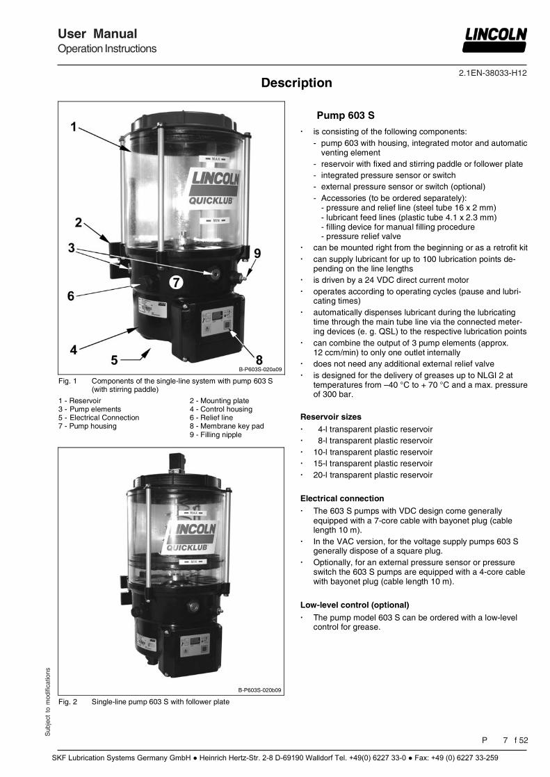
Fig. 1 Components of the single-line system with pump 603 S (with stirring paddle)
1 - Reservoir 2 - Mounting plate 3 - Pump elements 4 - Control housing 5 - Electrical Connection 6 - Relief line 7 - Pump housing 8 - Membrane key pad 9 - Filling nipple
B-P603S-020b09
Fig. 2 Single-line pump 603 S with follower plate
Pump 603 S
is consisting of the following components: - pump 603 with housing, integrated motor and automatic
venting element - reservoir with fixed and stirring paddle or follower plate - integrated pressure sensor or switch - external pressure sensor or switch (optional) - Accessories (to be ordered separately):
- pressure and relief line (steel tube 16 x 2 mm) - lubricant feed lines (plastic tube 4.1 x 2.3 mm) - filling device for manual filling procedure - pressure relief valve
can be mounted right from the beginning or as a retrofit kit can supply lubricant for up to 100 lubrication points de-
pending on the line lengths is driven by a 24 VDC direct current motor operates according to operating cycles (pause and lubri-
cating times) automatically dispenses lubricant during the lubricating
time through the main tube line via the connected meter-ing devices (e. g. QSL) to the respective lubrication points
can combine the output of 3 pump elements (approx. 12 ccm/min) to only one outlet internally
does not need any additional external relief valve is designed for the delivery of greases up to NLGI 2 at
temperatures from –40 °C to + 70 °C and a max. pressure of 300 bar.
Reservoir sizes
4-l transparent plastic reservoir 8-l transparent plastic reservoir 10-l transparent plastic reservoir 15-l transparent plastic reservoir 20-l transparent plastic reservoir
Electrical connection
The 603 S pumps with VDC design come generally equipped with a 7-core cable with bayonet plug (cable length 10 m).
In the VAC version, for the voltage supply pumps 603 S generally dispose of a square plug.
Optionally, for an external pressure sensor or pressure switch the 603 S pumps are equipped with a 4-core cable with bayonet plug (cable length 10 m).
Low-level control (optional)
The pump model 603 S can be ordered with a low-level control for grease.
Description
SKF Lubrication Systems Germany GmbH ● Heinrich Hertz-Str. 2-8 D-69190 Walldorf Tel. +49(0) 6227 33-0 ● Fax: +49 (0) 6227 33-259
2.1EN-38033-H12
Pag 8 f 52
User ManualOperation Instructions
Sub
ject
to
mod
ifica
tions
Identification Code – Single-Line Pump 603S
Code examples:
6001a02
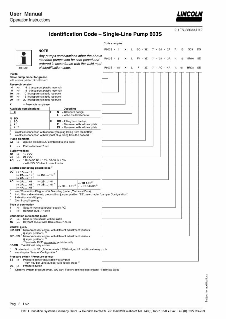
NOTE
Any pumps combinations other the above standard pumps can be com-posed and ordered in accordance with the valid mod-el identification code.
P603S - 4 X L BO - 3Z 7 - 24 - 2A 7. 16 S03 DS
P603S - 8 X L F1 - 3Z 7 - 24 - 3A 7. 16 SR16 SE
P603S - 15 X L F - 3Z 7 - AC - 4A 1. 01 BR08 SE
P603S
Basic pump model for grease with control printed circuit board
Reservoir version 4 >> 4 l transparent plastic reservoir 8 >> 8 l transparent plastic reservoir 10 >> 10 l transparent plastic reservoir 15 >> 15 l transparent plastic reservoir 20 >> 20 l transparent plastic reservoir
X = Reservoir for grease Available combinations Decoding
I II N BO L BO L F 1) L F1 2)
I N = Standard design L = with Low-level control
II BO = Filling from the top F = Reservoir with follower plate F1 = Reservoir with follower plate
1) electrical connection with square-type plug (filling from the bottom) 2) electrical connection with bayonet plug (filling from the bottom)
Pump elements 3Z >> 3 pump elements Z7 combined to one outlet
7 >> Piston diameter 7 mm
Supply voltage 12 >> 12 VDC 24 >> 24 VDC AC >> 110-240V AC 10%, 50-60Hz 5% - with 24V DC direct current motor
Electric connecting possibilities 3)
DC >> 1A …7.16 >> 2A …7.16 4) >> 3A …7.16 4)
>> 2B …7.16 4)
AC >> 2A …1.01 >> 3A …1.01 4) >> 4A …1.01 4)
>> 2B …1.01 >> 3B …1.01 4)
>> 3C …1.01 4)
>> 2D 1.01 5)
-…- K2 oderK3 6)
3) see “Connection Diagrams” & Decoding (under „Technical Data) 4) incl. 10 m cable (4-wire); precondition jumper position “2S”: see chapter “Jumper Configuration” 5) Indication via M12 plug 6) 2 or 3 coupling relay Type of connection 1 >> Square-type plug (power supply AC) 7 >> Bayonet plug, 7/7-pole
Connection outside the pump 01 >> Square-type socket without cable 16 >> Bayonet socket with 10 m cable (7-core)
Control p.c.b. S01-S24 7) Microprocessor control with different adjustment variants (jumper positions) 8)
B01-B24 7) Microprocessor control with different adjustment variants (jumper positions) 8)
- Terminals 15/30 connected pcb-internally SR/BR… 7) Additional relay control
7) S: standard p.c.b. / B: „S“ + terminals 15/30 bridged / R: additional relay p.c.b. 8) see chapter “Jumper Configuration” Pressure switch / Pressure sensor SE >> Pressure sensor adjustable via key pad - from 100 bar up to 320 bar with 10 bar steps 9) DS >> Pressure switch
9) Observe system pressure (max. 300 bar)! Factory settings: see chapter “Technical Data”
SKF Lubrication Systems Germany GmbH ● Heinrich Hertz-Str. 2-8 D-69190 Walldorf Tel. +49(0) 6227 33-0 ● Fax: +49 (0) 6227 33-259
2.1EN-38033-H12
Sub
ject
to
mod
ifica
tions
User ManualOperation Instructions
P 9 f 52
6741b07
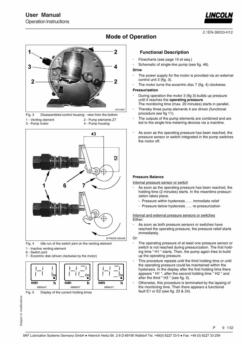
Fig. 3 Disassembled control housing - view from the bottom
1 - Venting element 2 - Pump elements Z7 3 - Pump motor 4 - Pump housing
B-P603S-030o08
Fig. 4 Idle run of the switch joint on the venting element
1 - Inactive venting element 6 - Switch joint 7 - Eccentric disk (driven clockwise by the motor)
6868a07
6868b07
6868c07
Fig. 5 Display of the current holding times
Functional Description
Flowcharts (see page 15 et seq.) Schematic of single-line pump (see fig. 46).
Drive
The power supply for the motor is provided via an external control unit 3 (fig. 3).
The motor turns the eccentric disc 7 (fig. 4) clockwise.
Pressurization
During operation the motor 3 (fig 3) builds up pressure until it reaches the operating pressure. The monitoring time (max. 20 minutes) starts in parallel.
Thereby three pump elements 4 are driven (functional procedure see fig 11).
The outputs of the pump elements are combined and are led to the single-line metering devices via a mainline.
As soon as the operating pressure has been reached, the
pressure sensor or switch integrated in the pump switches the motor off.
Pressure Balance
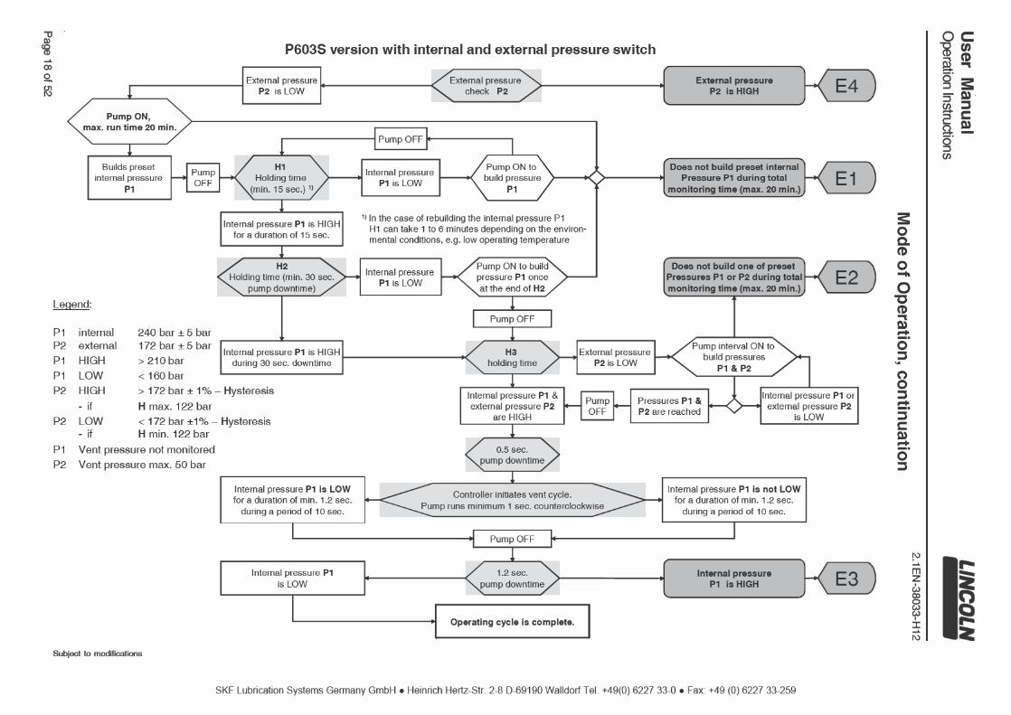
Internal pressure sensor or switch As soon as the operating pressure has been reached, the
holding time (2 minutes) starts. In the meantime pressuri-zation takes place. - Pressure within hysteresis…… immediate relief - Pressure below hysteresis ….. re-pressurization
Internal and external pressure sensors or switches Either: As soon as both pressure sensors or switches have
reached the operating pressure, the pressure relief starts immediately.
Or: The operating pressure of at least one pressure sensor or
switch is not reached during pressurization. The first hold-ing time “ H1 “ starts. Then, the pump again tries to build up the operating pressure.
This procedure repeats until the third holding time or until the operating pressure could be maintained within the hysteresis. In the display after the first holding time there appears " H1 ", after the second holding time " H2 " and after the third " H3 " (see fig. 5).
Otherwise, this procedure is terminated by the lapsing of the monitoring time. Then there appears a functional fault E1 or E2 (see fig. 23 & 24).
Mode of Operation
SKF Lubrication Systems Germany GmbH ● Heinrich Hertz-Str. 2-8 D-69190 Walldorf Tel. +49(0) 6227 33-0 ● Fax: +49 (0) 6227 33-259
2.1EN-38033-H12
Pag 10 f 52
User ManualOperation Instructions
Sub
ject
to
mod
ifica
tions
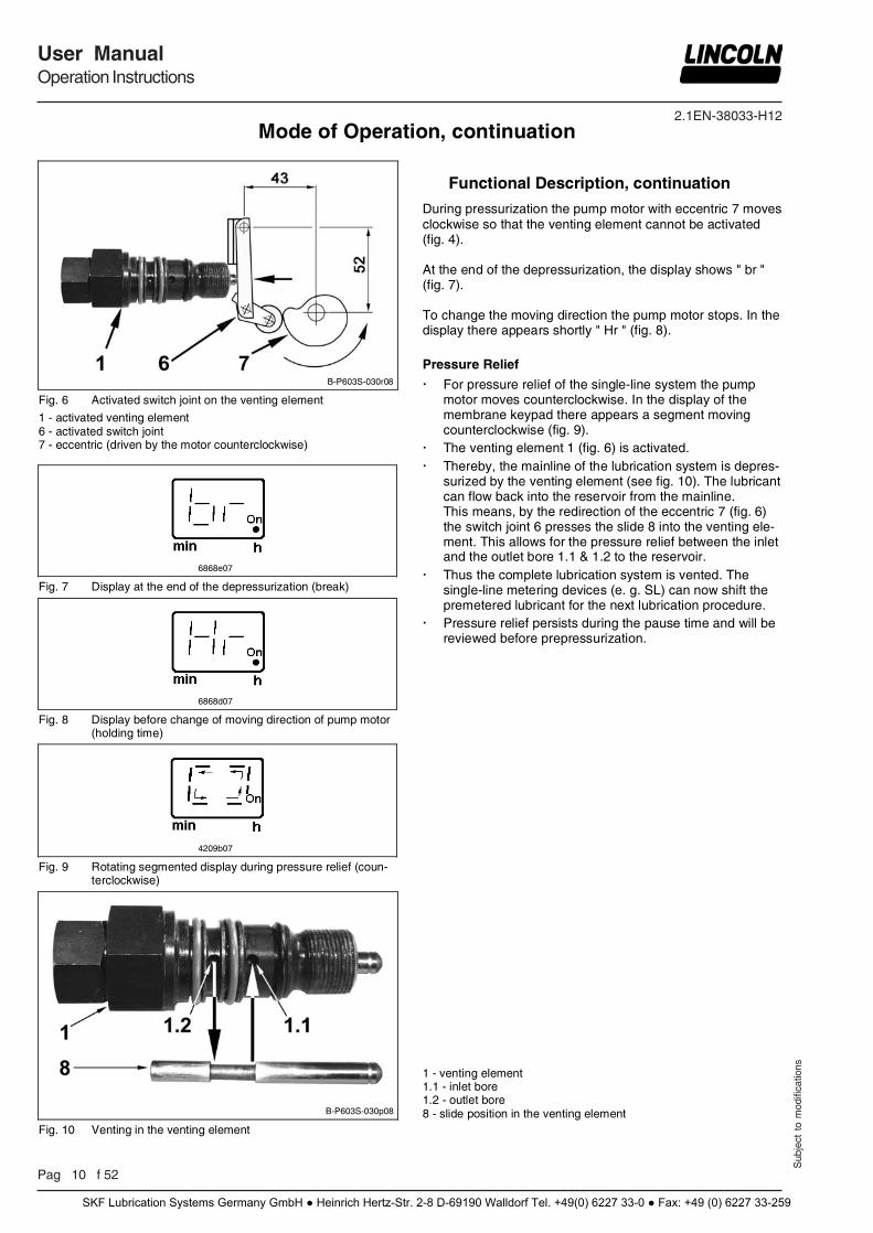
B-P603S-030r08
Fig. 6 Activated switch joint on the venting element
1 - activated venting element 6 - activated switch joint 7 - eccentric (driven by the motor counterclockwise)
6868e07
Fig. 7 Display at the end of the depressurization (break)
6868d07
Fig. 8 Display before change of moving direction of pump motor (holding time)
4209b07
Fig. 9 Rotating segmented display during pressure relief (coun-terclockwise)
Functional Description, continuation
During pressurization the pump motor with eccentric 7 moves clockwise so that the venting element cannot be activated (fig. 4). At the end of the depressurization, the display shows " br " (fig. 7). To change the moving direction the pump motor stops. In the display there appears shortly " Hr " (fig. 8). Pressure Relief
For pressure relief of the single-line system the pump motor moves counterclockwise. In the display of the membrane keypad there appears a segment moving counterclockwise (fig. 9).
The venting element 1 (fig. 6) is activated. Thereby, the mainline of the lubrication system is depres-
surized by the venting element (see fig. 10). The lubricant can flow back into the reservoir from the mainline. This means, by the redirection of the eccentric 7 (fig. 6) the switch joint 6 presses the slide 8 into the venting ele-ment. This allows for the pressure relief between the inlet and the outlet bore 1.1 & 1.2 to the reservoir.
Thus the complete lubrication system is vented. The single-line metering devices (e. g. SL) can now shift the premetered lubricant for the next lubrication procedure.
Pressure relief persists during the pause time and will be reviewed before prepressurization.
B-P603S-030p08
Fig. 10 Venting in the venting element
1 - venting element 1.1 - inlet bore 1.2 - outlet bore 8 - slide position in the venting element
Mode of Operation, continuation
SKF Lubrication Systems Germany GmbH ● Heinrich Hertz-Str. 2-8 D-69190 Walldorf Tel. +49(0) 6227 33-0 ● Fax: +49 (0) 6227 33-259
2.1EN-38033-H12
Sub
ject
to
mod
ifica
tions
User ManualOperation Instructions
P 11 f 52
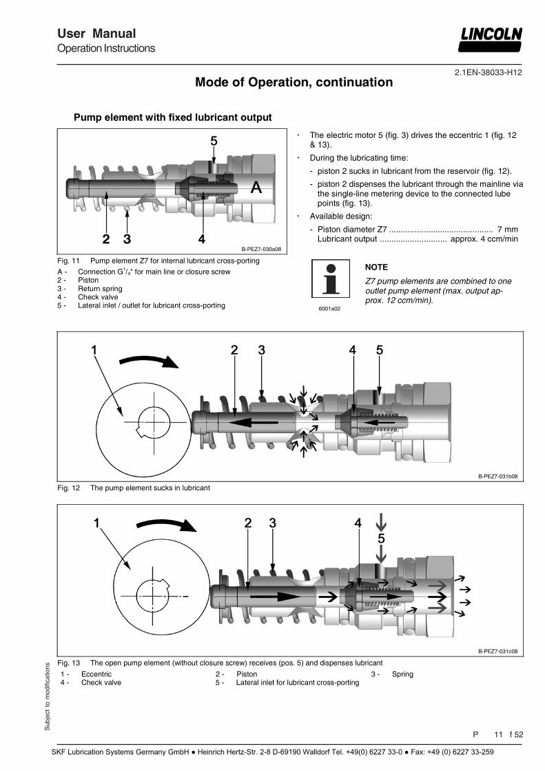
Pump element with fixed lubricant output
B-PEZ7-030a08
Fig. 11 Pump element Z7 for internal lubricant cross-porting
A - Connection G1/4" for main line or closure screw 2 - Piston 3 - Return spring 4 - Check valve 5 - Lateral inlet / outlet for lubricant cross-porting
The electric motor 5 (fig. 3) drives the eccentric 1 (fig. 12 & 13).
During the lubricating time:
- piston 2 sucks in lubricant from the reservoir (fig. 12).
- piston 2 dispenses the lubricant through the mainline via the single-line metering device to the connected lube points (fig. 13).
Available design:
- Piston diameter Z7 ............................................. 7 mm Lubricant output ............................. approx. 4 ccm/min
6001a02
NOTE
Z7 pump elements are combined to one outlet pump element (max. output ap-prox. 12 ccm/min).
B-PEZ7-031b08
Fig. 12 The pump element sucks in lubricant
B-PEZ7-031c08
Fig. 13 The open pump element (without closure screw) receives (pos. 5) and dispenses lubricant
1 - Eccentric 2 - Piston 3 - Spring 4 - Check valve 5 - Lateral inlet for lubricant cross-porting
Mode of Operation, continuation
SKF Lubrication Systems Germany GmbH ● Heinrich Hertz-Str. 2-8 D-69190 Walldorf Tel. +49(0) 6227 33-0 ● Fax: +49 (0) 6227 33-259
2.1EN-38033-H12
Pag 12 f 52
User ManualOperation Instructions
Sub
ject
to
mod
ifica
tions
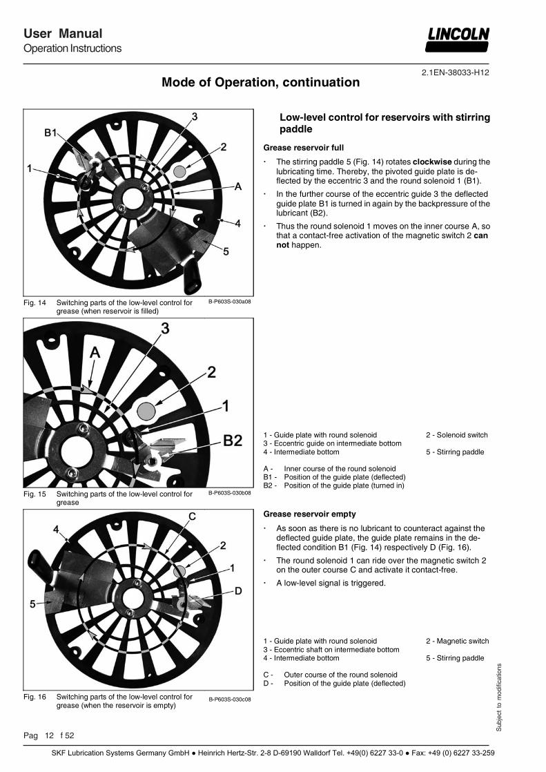
Fig. 14 Switching parts of the low-level control for
grease (when reservoir is filled) B-P603S-030a08
Fig. 15 Switching parts of the low-level control for
grease B-P603S-030b08
Fig. 16 Switching parts of the low-level control for
grease (when the reservoir is empty) B-P603S-030c08
Low-level control for reservoirs with stirring paddle
Grease reservoir full
The stirring paddle 5 (Fig. 14) rotates clockwise during the lubricating time. Thereby, the pivoted guide plate is de-flected by the eccentric 3 and the round solenoid 1 (B1).
In the further course of the eccentric guide 3 the deflected guide plate B1 is turned in again by the backpressure of the lubricant (B2).
Thus the round solenoid 1 moves on the inner course A, so that a contact-free activation of the magnetic switch 2 can not happen.
1 - Guide plate with round solenoid 2 - Solenoid switch 3 - Eccentric guide on intermediate bottom 4 - Intermediate bottom 5 - Stirring paddle A - Inner course of the round solenoid B1 - Position of the guide plate (deflected) B2 - Position of the guide plate (turned in)
Grease reservoir empty
As soon as there is no lubricant to counteract against the deflected guide plate, the guide plate remains in the de-flected condition B1 (Fig. 14) respectively D (Fig. 16).
The round solenoid 1 can ride over the magnetic switch 2 on the outer course C and activate it contact-free.
A low-level signal is triggered. 1 - Guide plate with round solenoid 2 - Magnetic switch 3 - Eccentric shaft on intermediate bottom 4 - Intermediate bottom 5 - Stirring paddle C - Outer course of the round solenoid D - Position of the guide plate (deflected)
Mode of Operation, continuation
SKF Lubrication Systems Germany GmbH ● Heinrich Hertz-Str. 2-8 D-69190 Walldorf Tel. +49(0) 6227 33-0 ● Fax: +49 (0) 6227 33-259
2.1EN-38033-H12
Sub
ject
to
mod
ifica
tions
User ManualOperation Instructions
P 13 f 52
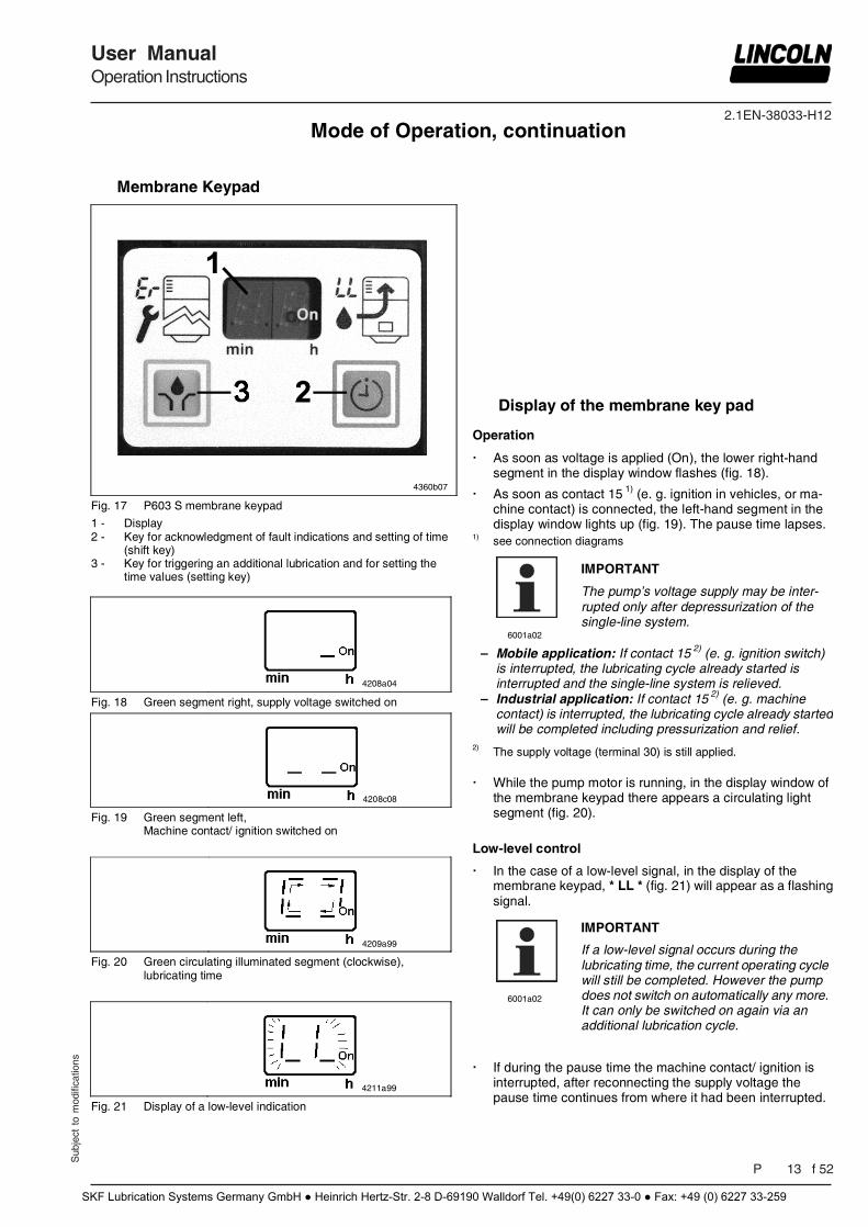
Membrane Keypad
4360b07
Fig. 17 P603 S membrane keypad
1 - Display 2 - Key for acknowledgment of fault indications and setting of time
(shift key) 3 - Key for triggering an additional lubrication and for setting the
time values (setting key)
4208a04
Fig. 18 Green segment right, supply voltage switched on
4208c08
Fig. 19 Green segment left, Machine contact/ ignition switched on
4209a99
Fig. 20 Green circulating illuminated segment (clockwise), lubricating time
4211a99
Fig. 21 Display of a low-level indication
Display of the membrane key pad
Operation
As soon as voltage is applied (On), the lower right-hand segment in the display window flashes (fig. 18).
As soon as contact 15 1) (e. g. ignition in vehicles, or ma-chine contact) is connected, the left-hand segment in the display window lights up (fig. 19). The pause time lapses.
1) see connection diagrams
6001a02
IMPORTANT
The pump’s voltage supply may be inter-rupted only after depressurization of the single-line system.
– –
Mobile application: If contact 15 2) (e. g. ignition switch) is interrupted, the lubricating cycle already started is interrupted and the single-line system is relieved. Industrial application: If contact 15 2) (e. g. machine contact) is interrupted, the lubricating cycle already started will be completed including pressurization and relief.
2) The supply voltage (terminal 30) is still applied.
While the pump motor is running, in the display window of the membrane keypad there appears a circulating light segment (fig. 20).
Low-level control
In the case of a low-level signal, in the display of the membrane keypad, * LL * (fig. 21) will appear as a flashing signal.
6001a02
IMPORTANT
If a low-level signal occurs during the lubricating time, the current operating cycle will still be completed. However the pump does not switch on automatically any more. It can only be switched on again via an additional lubrication cycle.
If during the pause time the machine contact/ ignition is interrupted, after reconnecting the supply voltage the pause time continues from where it had been interrupted.
Mode of Operation, continuation
SKF Lubrication Systems Germany GmbH ● Heinrich Hertz-Str. 2-8 D-69190 Walldorf Tel. +49(0) 6227 33-0 ● Fax: +49 (0) 6227 33-259
2.1EN-38033-H12
Pag 14 f 52
User ManualOperation Instructions
Sub
ject
to
mod
ifica
tions
Display of the membrane key pad, continuation
6839b07
…
6842b07
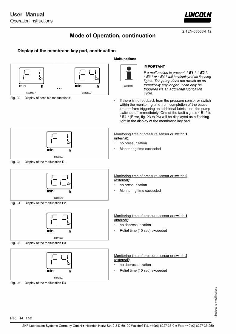
Fig. 22 Display of poss ble malfunctions
Malfunctions
6001a02
IMPORTANT
If a malfunction is present, * E1 *, * E2 *, * E3 * or * E4 * will be displayed as flashing lights. The pump does not switch on au-tomatically any longer. It can only be triggered via an additional lubrication cycle.
If there is no feedback from the pressure sensor or switch within the monitoring time from completion of the pause time or from triggering an additional lubrication, the pump switches off immediately. One of the fault signals * E1 * to * E4 * (Error, fig. 23 to 26) will be displayed as a flashing light in the display of the membrane key pad.
6839b07
Fig. 23 Display of the malfunction E1
Monitoring time of pressure sensor or switch 1 (internal): no pressurization
Monitoring time exceeded
6840b07
Fig. 24 Display of the malfunction E2
Monitoring time of pressure sensor or switch 2 (external): no pressurization
Monitoring time exceeded
6841b07
Fig. 25 Display of the malfunction E3
Monitoring time of pressure sensor or switch 1 (internal): no depressurization
Relief time (10 sec) exceeded
6842b07
Fig. 26 Display of the malfunction E4
Monitoring time of pressure sensor or switch 2 (external): no depressurization
Relief time (10 sec) exceeded
Mode of Operation, continuation
SKF Lubrication Systems Germany GmbH ● Heinrich Hertz-Str. 2-8 D-69190 Walldorf Tel. +49(0) 6227 33-0 ● Fax: +49 (0) 6227 33-259
2.1EN-38033-H12
Sub
ject
to
mod
ifica
tions
User ManualOperation Instructions
P 19 f 52
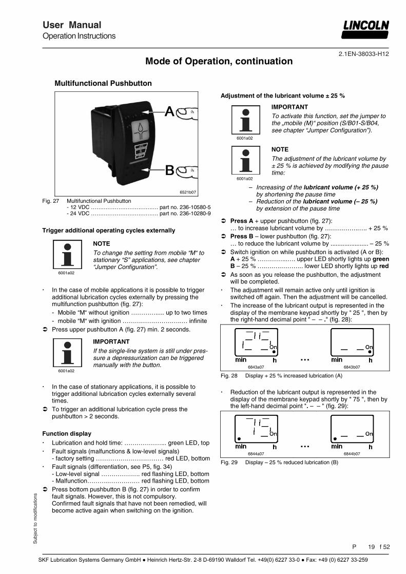
Multifunctional Pushbutton
6521b07
Fig. 27 Multifunctional Pushbutton - 12 VDC ………………………………. part no. 236-10580-5 - 24 VDC ………………………………. part no. 236-10280-9
Trigger additional operating cycles externally
6001a02
NOTE
To change the setting from mobile “M“ to stationary “S” applications, see chapter “Jumper Configuration”.
In the case of mobile applications it is possible to trigger
additional lubrication cycles externally by pressing the multifunction pushbutton (fig. 27): - Mobile “M“ without ignition …………..... up to two times - mobile “M“ with ignition ………………………..… infinite
Press upper pushbutton A (fig. 27) min. 2 seconds.
6001a02
IMPORTANT
If the single-line system is still under pres-sure a depressurization can be triggered manually with the button.
In the case of stationary applications, it is possible to
trigger additional lubrication cycles externally several times.
To trigger an additional lubrication cycle press the pushbutton > 2 seconds.
Function display
Lubrication and hold time: ………………... green LED, top Fault signals (malfunctions & low-level signals)
- factory setting …………………………… red LED, bottom Fault signals (differentiation, see P5, fig. 34)
- Low-level signal ………………. red flashing LED, bottom - Malfunction………..…………… red flashing LED, bottom
Press bottom pushbutton B (fig. 27) in order to confirm fault signals. However, this is not compulsory. Confirmed fault signals that have not been remedied, will become active again when switching on the ignition.
Adjustment of the lubricant volume ± 25 %
6001a02
IMPORTANT To activate this function, set the jumper to the „mobile (M)“ position (S/B01-S/B04, see chapter “Jumper Configuration”).
6001a02
NOTE
The adjustment of the lubricant volume by ± 25 % is achieved by modifying the pause time:
– –
Increasing of the lubricant volume (+ 25 %) by shortening the pause time Reduction of the lubricant volume (– 25 %) by extension of the pause time
Press A + upper pushbutton (fig. 27): … to increase lubricant volume by ……………..…. + 25 %
Press B – lower pushbutton (fig. 27): … to reduce the lubricant volume by ...................... – 25 %
Switch ignition on while pushbutton is activated (A or B): A + 25 % …………...…. upper LED shortly lights up green B – 25 % ….….….……….. lower LED shortly lights up red
As soon as you release the pushbutton, the adjustment will be completed.
The adjustment will remain active only until ignition is switched off again. Then the adjustment will be cancelled.
The increase of the lubricant output is represented in the display of the membrane keypad shortly by " 25 ", then by the right-hand decimal point " – – ." (fig. 28):
6843a07
…
6843b07
Fig. 28 Display + 25 % increased lubrication (A)
Reduction of the lubricant output is represented in the display of the membrane keypad shortly by " 75 ", then by the left-hand decimal point ". – – " (fig. 29):
6844a07
…
6844b07
Fig. 29 Display – 25 % reduced lubrication (B)
Mode of Operation, continuation
SKF Lubrication Systems Germany GmbH ● Heinrich Hertz-Str. 2-8 D-69190 Walldorf Tel. +49(0) 6227 33-0 ● Fax: +49 (0) 6227 33-259
2.1EN-38033-H12
Pag 20 f 52
User ManualOperation Instructions
Sub
ject
to
mod
ifica
tions
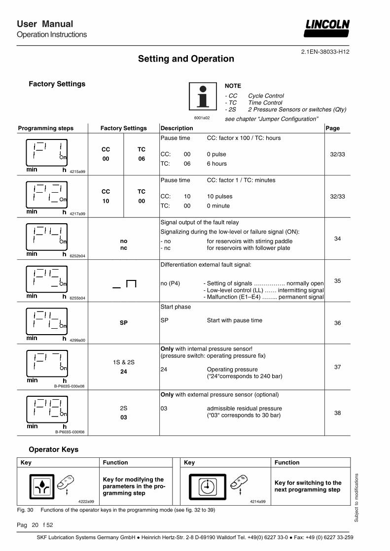
Factory Settings
6001a02
NOTE
- CC Cycle Control - TC Time Control - 2S 2 Pressure Sensors or switches (Qty)
see chapter “Jumper Configuration”
Programming steps Factory Settings Description Page
4215a99
CC
00
TC
06
Pause time CC: factor x 100 / TC: hours
CC: 00 0 pulse
TC: 06 6 hours
32/33
4217a99
CC
10
TC
00
Pause time CC: factor 1 / TC: minutes
CC: 10 10 pulses
TC: 00 0 minute
32/33
6252b04
no nc
Signal output of the fault relay
Signalizing during the low-level or failure signal (ON):
- no for reservoirs with stirring paddle - nc for reservoirs with follower plate
34
6255b04
Differentiation external fault signal:
no (P4) - Setting of signals ……………. normally open - Low-level control (LL) …… intermitting signal - Malfunction (E1–E4) …….. permanent signal
35
4299a00
SP
Start phase SP Start with pause time 36
B-P603S-030e08
1S & 2S
24
Only with internal pressure sensor! (pressure switch: operating pressure fix) 24 Operating pressure (“24“corresponds to 240 bar)
37
B-P603S-030f08
2S
03
Only with external pressure sensor (optional) 03 admissible residual pressure (“03“ corresponds to 30 bar) 38
Operator Keys
Key Function Key Function
4222a99
Key for modifying the parameters in the pro-gramming step
4214a99
Key for switching to the next programming step
Fig. 30 Functions of the operator keys in the programming mode (see fig. 32 to 39)
Setting and Operation
SKF Lubrication Systems Germany GmbH ● Heinrich Hertz-Str. 2-8 D-69190 Walldorf Tel. +49(0) 6227 33-0 ● Fax: +49 (0) 6227 33-259
2.1EN-38033-H12
Sub
ject
to
mod
ifica
tions
User ManualOperation Instructions
P 21 f 52
Three possible modes of operation and settings can be select-ed on the keypad.
Display mode Programming mode (fig. 32 ff) Operating mode (fig. 40 & 41)
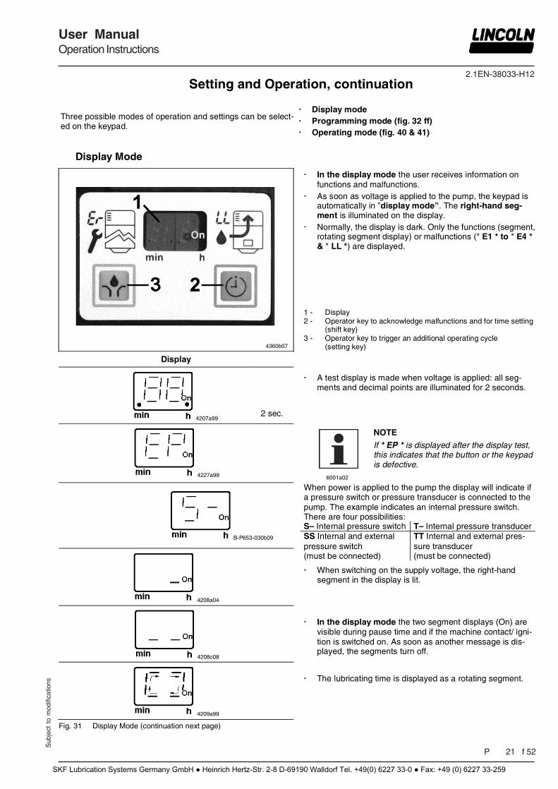
Display Mode
4360b07
In the display mode the user receives information on functions and malfunctions.
As soon as voltage is applied to the pump, the keypad is automatically in ”display mode”. The right-hand seg-ment is illuminated on the display.
Normally, the display is dark. Only the functions (segment, rotating segment display) or malfunctions (* E1 * to * E4 * & * LL *) are displayed.
1 - Display 2 - Operator key to acknowledge malfunctions and for time setting
(shift key) 3 - Operator key to trigger an additional operating cycle
(setting key)
Display
4207a99 2 sec.
4227a99
A test display is made when voltage is applied: all seg-
ments and decimal points are illuminated for 2 seconds.
6001a02
NOTE
If * EP * is displayed after the display test, this indicates that the button or the keypad is defective.
B-P653-030b09
4208a04
4208c08
When power is applied to the pump the display will indicate if a pressure switch or pressure transducer is connected to the pump. The example indicates an internal pressure switch. There are four possibilities: S– Internal pressure switch T– Internal pressure transducer SS Internal and external pressure switch (must be connected)
TT Internal and external pres-sure transducer (must be connected)
When switching on the supply voltage, the right-hand
segment in the display is lit. In the display mode the two segment displays (On) are
visible during pause time and if the machine contact/ igni-tion is switched on. As soon as another message is dis-played, the segments turn off.
4209a99
Fig. 31 Display Mode (continuation next page)
The lubricating time is displayed as a rotating segment.
Setting and Operation, continuation
SKF Lubrication Systems Germany GmbH ● Heinrich Hertz-Str. 2-8 D-69190 Walldorf Tel. +49(0) 6227 33-0 ● Fax: +49 (0) 6227 33-259
2.1EN-38033-H12
Pag 22 f 52
User ManualOperation Instructions
Sub
ject
to
mod
ifica
tions
Display Mode, continuation
Press Display
6839b07
6842b07
4211a99
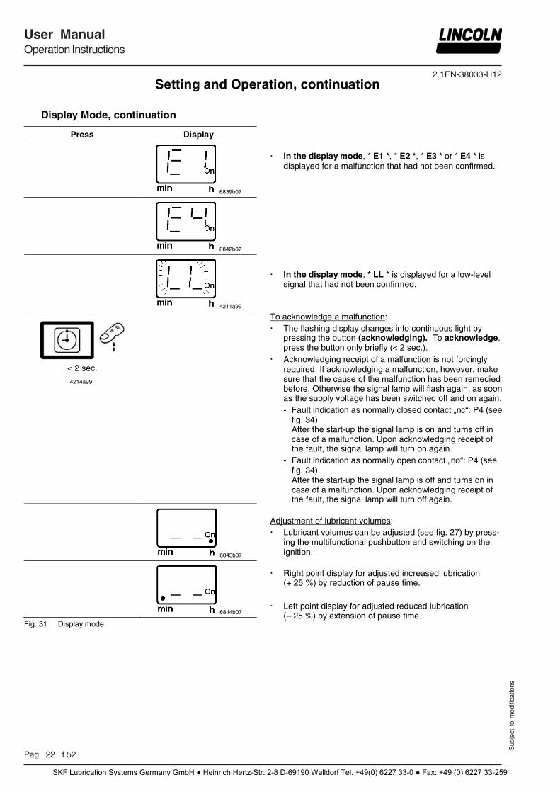
In the display mode, * E1 *, * E2 *, * E3 * or * E4 * is
displayed for a malfunction that had not been confirmed.
In the display mode, * LL * is displayed for a low-level signal that had not been confirmed.
< 2 sec.
4214a99
6843b07
6844b07
Fig. 31 Display mode
To acknowledge a malfunction: The flashing display changes into continuous light by
pressing the button (acknowledging). To acknowledge, press the button only briefly (< 2 sec.).
Acknowledging receipt of a malfunction is not forcingly required. If acknowledging a malfunction, however, make sure that the cause of the malfunction has been remedied before. Otherwise the signal lamp will flash again, as soon as the supply voltage has been switched off and on again. - Fault indication as normally closed contact „nc“: P4 (see
fig. 34) After the start-up the signal lamp is on and turns off in case of a malfunction. Upon acknowledging receipt of the fault, the signal lamp will turn on again.
- Fault indication as normally open contact „no“: P4 (see fig. 34) After the start-up the signal lamp is off and turns on in case of a malfunction. Upon acknowledging receipt of the fault, the signal lamp will turn off again.
Adjustment of lubricant volumes: Lubricant volumes can be adjusted (see fig. 27) by press-
ing the multifunctional pushbutton and switching on the ignition.
Right point display for adjusted increased lubrication (+ 25 %) by reduction of pause time.
Left point display for adjusted reduced lubrication
(– 25 %) by extension of pause time.
Setting and Operation, continuation
SKF Lubrication Systems Germany GmbH ● Heinrich Hertz-Str. 2-8 D-69190 Walldorf Tel. +49(0) 6227 33-0 ● Fax: +49 (0) 6227 33-259
2.1EN-38033-H12
Sub
ject
to
mod
ifica
tions
User ManualOperation Instructions
P 23 f 52
Programming Mode, time-controlled
Press Display 4214a99
4222a99
> 4 sec.
4215a99
Factory setting
4281a00
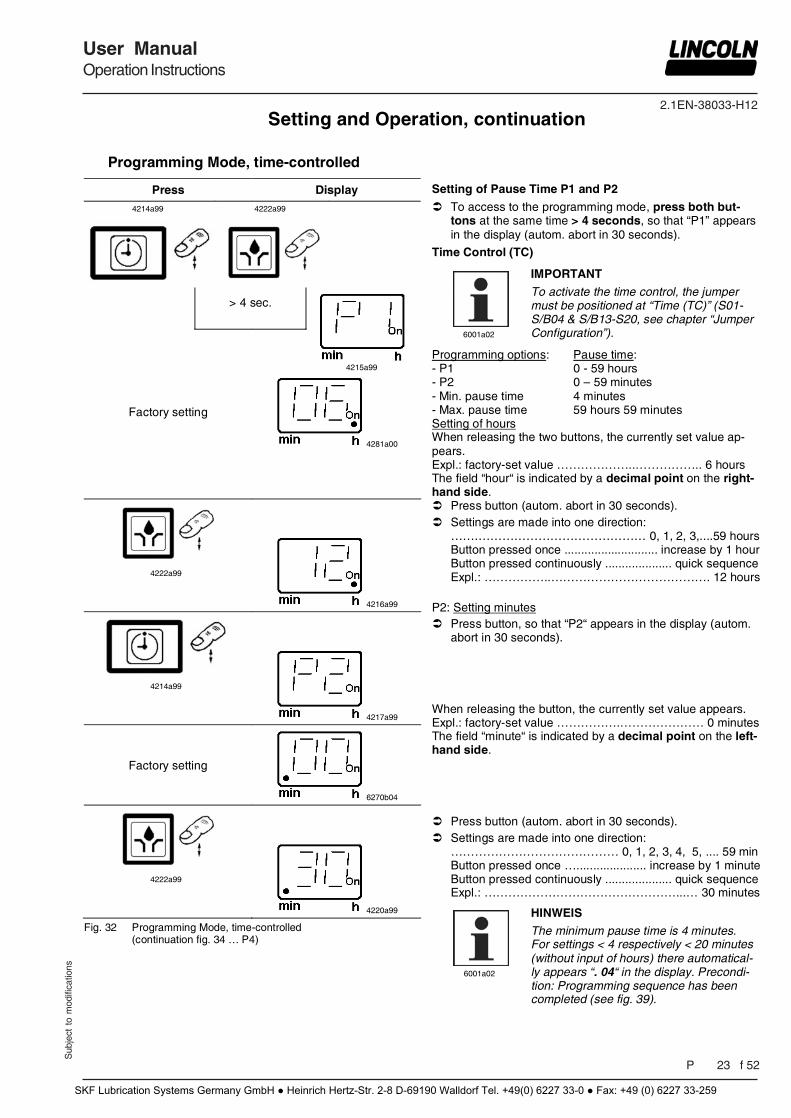
Setting of Pause Time P1 and P2
To access to the programming mode, press both but-tons at the same time > 4 seconds, so that “P1” appears in the display (autom. abort in 30 seconds).
Time Control (TC)
6001a02
IMPORTANT
To activate the time control, the jumper must be positioned at “Time (TC)” (S01-S/B04 & S/B13-S20, see chapter “Jumper Configuration”).
Programming options: Pause time: - P1 0 - 59 hours - P2 0 – 59 minutes - Min. pause time 4 minutes - Max. pause time 59 hours 59 minutes Setting of hours When releasing the two buttons, the currently set value ap-pears. Expl.: factory-set value ………………..…………….. 6 hours The field “hour“ is indicated by a decimal point on the right-hand side.
4222a99
4216a99
4214a99
4217a99
Factory setting
6270b04
4222a99
4220a99
Fig. 32 Programming Mode, time-controlled (continuation fig. 34 … P4)
Press button (autom. abort in 30 seconds). Settings are made into one direction:
…….…………………………………… 0, 1, 2, 3,....59 hours Button pressed once ............................ increase by 1 hour Button pressed continuously .................... quick sequence Expl.: ……………..…………………………………. 12 hours
P2: Setting minutes Press button, so that “P2“ appears in the display (autom.
abort in 30 seconds). When releasing the button, the currently set value appears. Expl.: factory-set value …………….………………… 0 minutes The field “minute“ is indicated by a decimal point on the left-hand side. Press button (autom. abort in 30 seconds). Settings are made into one direction:
…………………………………… 0, 1, 2, 3, 4, 5, .... 59 min Button pressed once …..................... increase by 1 minuteButton pressed continuously .................... quick sequence Expl.: …………………………………………...… 30 minutes
6001a02
HINWEIS
The minimum pause time is 4 minutes. For settings < 4 respectively < 20 minutes (without input of hours) there automatical-ly appears “. 04“ in the display. Precondi-tion: Programming sequence has been completed (see fig. 39).
Setting and Operation, continuation
SKF Lubrication Systems Germany GmbH ● Heinrich Hertz-Str. 2-8 D-69190 Walldorf Tel. +49(0) 6227 33-0 ● Fax: +49 (0) 6227 33-259
2.1EN-38033-H12
Pag 24 f 52
User ManualOperation Instructions
Sub
ject
to
mod
ifica
tions
Programming Mode, cycle-controlled
Press Display 4214a99
4222a99
> 4 sec.
4215a99
Factory setting
6269b04
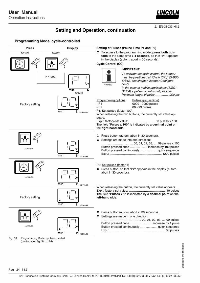
Setting of Pulses (Pause Time P1 and P2) To access to the programming mode, press both but-
tons at the same time > 4 seconds, so that “P1” appears in the display (autom. abort in 30 seconds).
Cycle Control (CC)
6001a02
IMPORTANT
To activate the cycle control, the jumper must be positioned at “Cycle (CC)” (S/B05-S/B12, see chapter “Jumper Configura-tion”). In the case of mobile applications (S/B01-S/B04) a pulse control is not possible. Minimum length of pulse ……...….. 200 ms
Programming options: Pulses (pause time): - P1 0000 - 9900 pulses - P2 00 - 99 pulses P1: Set pulses (factor 100) When releasing the two buttons, the currently set value ap-pears. Expl.: factory-set value: ….….……………… 00 pulses x 100 The field "Pulses x 100" is indicated by a decimal point on the right-hand side.
4222a99
4216a99
4214a99
4217a99
Factory setting
4226a99
4222a99
4220a99
Fig. 33 Programming Mode, cycle-controlled (continuation fig. 34 … P4)
Press button (autom. abort in 30 seconds). Settings are made into one direction:
…….........…….............. 00, 01, 02, 03, .... 99 pulses x 100 Button pressed once …................. increase by 100 pulses Button pressed continuously .................... quick sequence Expl.: ……………………..…………………….. 1200 pulses
P2: Set pulses (factor 1) Press button, so that “P2“ appears in the display (autom.
abort in 30 seconds). When releasing the button, the currently set value appears. Expl.: factory-set value: …………………………..….. 10 pulses The field "Pulses x 1" is indicated by a decimal point on the left-hand side. Press button (autom. abort in 30 seconds). Settings are made in one direction:
……………………………….... 00, 01, 02, 03, .... 99 pulses Button pressed once ………................ increase by 1 pulse Button pressed continuously ……............. quick sequence Expl.: …………………………………….………… 30 pulses
Setting and Operation, continuation
SKF Lubrication Systems Germany GmbH ● Heinrich Hertz-Str. 2-8 D-69190 Walldorf Tel. +49(0) 6227 33-0 ● Fax: +49 (0) 6227 33-259
2.1EN-38033-H12
Sub
ject
to
mod
ifica
tions
User ManualOperation Instructions
P 25 f 52
Programming Mode, Signal Output of Fault Relay
Press Display
4214a99
6252b04
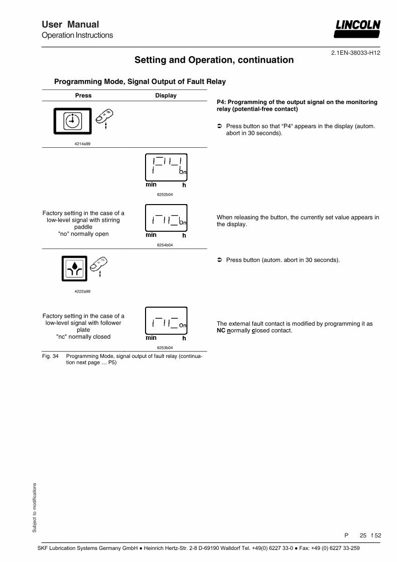
Factory setting in the case of a low-level signal with stirring
paddle "no" normally open
6254b04
4222a99
Factory setting in the case of a low-level signal with follower
plate "nc" normally closed
6253b04
Fig. 34 Programming Mode, signal output of fault relay (continua-tion next page … P5)
P4: Programming of the output signal on the monitoring relay (potential-free contact)
Press button so that “P4“ appears in the display (autom.
abort in 30 seconds). When releasing the button, the currently set value appears in the display. Press button (autom. abort in 30 seconds). The external fault contact is modified by programming it as NC normally closed contact.
Setting and Operation, continuation
SKF Lubrication Systems Germany GmbH ● Heinrich Hertz-Str. 2-8 D-69190 Walldorf Tel. +49(0) 6227 33-0 ● Fax: +49 (0) 6227 33-259
2.1EN-38033-H12
Pag 26 f 52
User ManualOperation Instructions
Sub
ject
to
mod
ifica
tions
Programming Mode, Signal Output of Fault Relay, continuation
Press Display
4214a99
6255b04
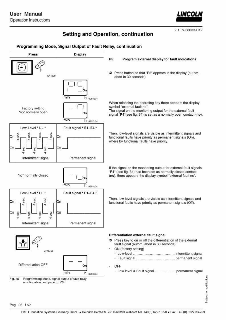
P5: Program external display for fault indications
Press button so that “P5“ appears in the display (autom.
abort in 30 seconds).
Factory setting "no" normally open
6257b04
When releasing the operating key there appears the display symbol “external fault no". The signal on the monitoring output for the external fault signal “P4“(see fig. 34) is set as a normally open contact (no).
Low-Level * LL * Fault signal * E1–E4 *
On
4 se
c.
4 se
c.
4 se
c.
4 se
c.
On
4 se
c.
4 se
c.
4 se
c.
Off
Off
Intermittent signal Permanent signal
Then, low-level signals are visible as intermittent signals and functional faults have priority as permanent signals (On), where by functional faults have priority.
"nc" normally closed
6258b04
If the signal on the monitoring output for external fault signals “P4“ (see fig. 34) has been set as normally closed contact (nc), there appears the display symbol “external fault nc”.
Low-Level * LL * Fault signal * E1–E4 *
On
4 se
c.
4 se
c.
4 se
c.
On
4 se
c.
4 se
c.
4 se
c.
4 se
c.
Off
Off
Intermittent signal Permanent signal
4222a99
Differentiation OFF
6256b04
Fig. 35 Programming Mode, signal output of fault relay (continuation next page … P6)
Then, low-level signals are visible as intermittent signals and functional faults have priority as permanent signals (Off). Differentiation external fault signal
Press key to on or off the differentiation of the external fault signal (autom. abort in 30 seconds):
ON (factory setting) - Low-level …………..………………….. intermittent signal - Fault signal ……………………………. permanent signal
OFF - Low-level & Fault signal ……………… permanent signal
Setting and Operation, continuation
SKF Lubrication Systems Germany GmbH ● Heinrich Hertz-Str. 2-8 D-69190 Walldorf Tel. +49(0) 6227 33-0 ● Fax: +49 (0) 6227 33-259
2.1EN-38033-H12
Sub
ject
to
mod
ifica
tions
User ManualOperation Instructions
P 27 f 52
Programming Mode, start phase
Press Display
4214a99
4299a00
Factory setting
6259b04
4222a99
6260b04
Fig. 36 Programming mode, start phase
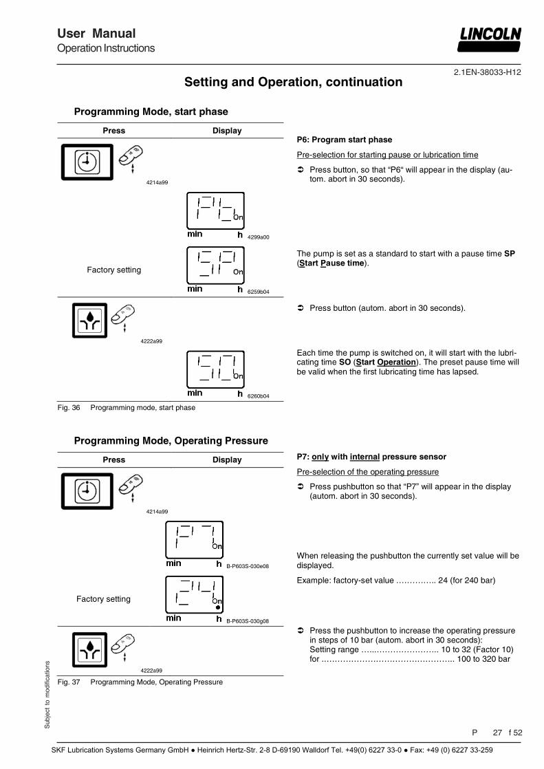
P6: Program start phase
Pre-selection for starting pause or lubrication time
Press button, so that “P6“ will appear in the display (au-tom. abort in 30 seconds).
The pump is set as a standard to start with a pause time SP (Start Pause time).
Press button (autom. abort in 30 seconds).
Each time the pump is switched on, it will start with the lubri-cating time SO (Start Operation). The preset pause time will be valid when the first lubricating time has lapsed.
Programming Mode, Operating Pressure
Press Display
4214a99
B-P603S-030e08
Factory setting
B-P603S-030g08
4222a99
Fig. 37 Programming Mode, Operating Pressure
P7: only with internal pressure sensor
Pre-selection of the operating pressure
Press pushbutton so that “P7” will appear in the display (autom. abort in 30 seconds).
When releasing the pushbutton the currently set value will be displayed.
Example: factory-set value .………….. 24 (for 240 bar)
Press the pushbutton to increase the operating pressure in steps of 10 bar (autom. abort in 30 seconds): Setting range …...………………….. 10 to 32 (Factor 10) for ..……………………………………….. 100 to 320 bar
Setting and Operation, continuation
SKF Lubrication Systems Germany GmbH ● Heinrich Hertz-Str. 2-8 D-69190 Walldorf Tel. +49(0) 6227 33-0 ● Fax: +49 (0) 6227 33-259
2.1EN-38033-H12
Pag 28 f 52
User ManualOperation Instructions
Sub
ject
to
mod
ifica
tions
Programming Mode, relief pressure
6001a02
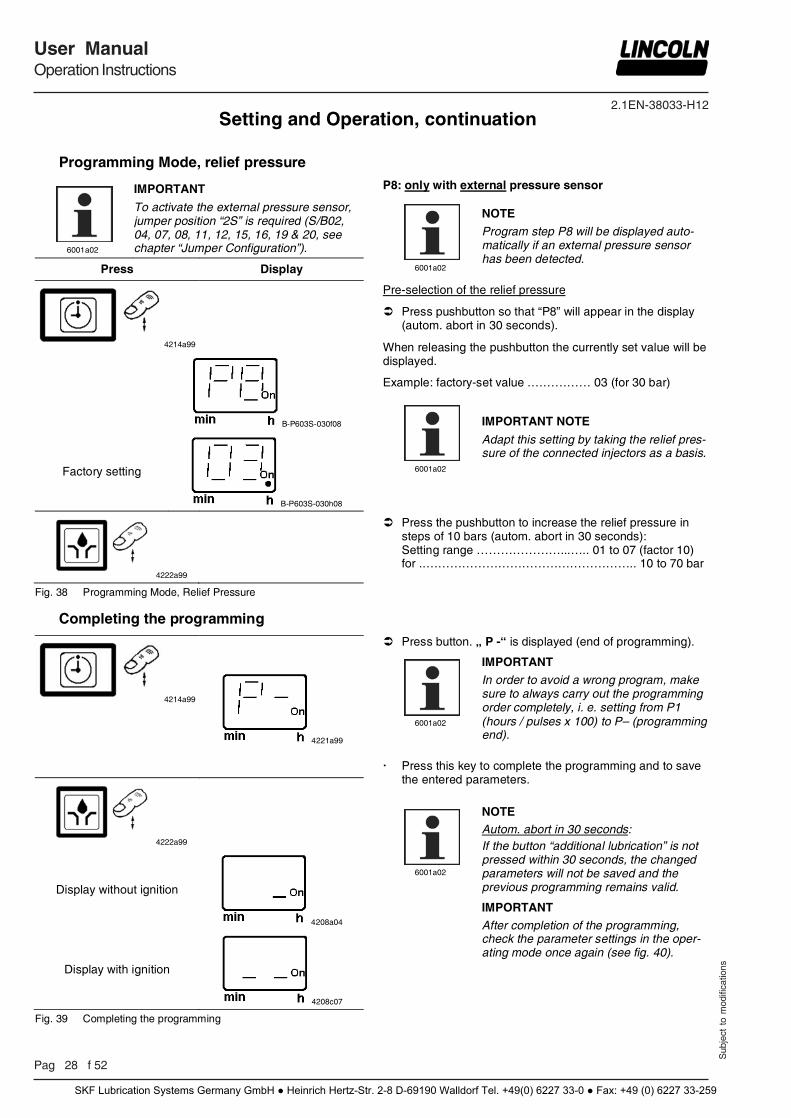
IMPORTANT
To activate the external pressure sensor, jumper position “2S” is required (S/B02, 04, 07, 08, 11, 12, 15, 16, 19 & 20, see chapter “Jumper Configuration”).
Press Display
4214a99
B-P603S-030f08
Factory setting
B-P603S-030h08
4222a99
Fig. 38 Programming Mode, Relief Pressure
P8: only with external pressure sensor
6001a02
NOTE
Program step P8 will be displayed auto-matically if an external pressure sensor has been detected.
Pre-selection of the relief pressure
Press pushbutton so that “P8” will appear in the display (autom. abort in 30 seconds).
When releasing the pushbutton the currently set value will be displayed.
Example: factory-set value .…………… 03 (for 30 bar)
6001a02
IMPORTANT NOTE
Adapt this setting by taking the relief pres-sure of the connected injectors as a basis.
Press the pushbutton to increase the relief pressure in steps of 10 bars (autom. abort in 30 seconds): Setting range …………………...….. 01 to 07 (factor 10) for ..…………………………………………….. 10 to 70 bar
Completing the programming
4214a99
4221a99
4222a99
Display without ignition
4208a04
Display with ignition
4208c07
Fig. 39 Completing the programming
Press button. „ P -“ is displayed (end of programming).
6001a02
IMPORTANT
In order to avoid a wrong program, make sure to always carry out the programming order completely, i. e. setting from P1 (hours / pulses x 100) to P– (programming end).
Press this key to complete the programming and to save the entered parameters.
6001a02
NOTE Autom. abort in 30 seconds: If the button “additional lubrication” is not pressed within 30 seconds, the changed parameters will not be saved and the previous programming remains valid.
IMPORTANT
After completion of the programming, check the parameter settings in the oper-ating mode once again (see fig. 40).
Setting and Operation, continuation
SKF Lubrication Systems Germany GmbH ● Heinrich Hertz-Str. 2-8 D-69190 Walldorf Tel. +49(0) 6227 33-0 ● Fax: +49 (0) 6227 33-259
2.1EN-38033-H12
Sub
ject
to
mod
ifica
tions
User ManualOperation Instructions
P 29 f 52
Operating Mode, additional lubrication
Press Display
Display with ignition switched off
4208a04
> 2 sec.
4222a99 4209a99
Display with ignition switch switched on
4208c07
Fig. 40 To trigger an additional lubrication
Operating Mode, calling up
Press Display
4214a99
Display
after two sec. after two sec.
4223a99 6858b07
after two sec. after two sec.
4216a99 4220a99
after two sec. with TC (Time Control) with CC (Cycle Control)
4224a99 6859b07
after two sec. after two sec.
4225c07 4226a99
Fig. 41 Operating Mode (continuation next page)
6001a02
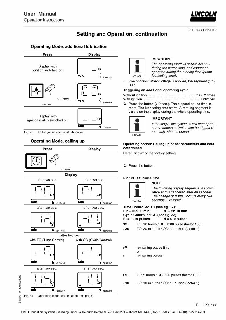
IMPORTANT
The operating mode is accessible only during the pause time, and cannot be operated during the running time (pump lubricating time).
Precondition: When voltage is applied, the segment (On) is lit.
Triggering an additional operating cycle
Without ignition ................................................ max. 2 times With ignition ........................................................... unlimited Press the button (> 2 sec.). The elapsed pause time is
reset. The lubricating time starts. A rotating segment is visible on the display during the whole operating time.
6001a02
IMPORTANT
If the single-line system is still under pres-sure a depressurization can be triggered manually with the button.
Operating option: Calling up of set parameters and data determined
Here: Display of the factory setting Press the button. PP / PI set pause time
6001a02
NOTE
The following display sequence is shown once and is cancelled after 40 seconds. The change of display occurs every two seconds. Example:
Time Controlled TC (see fig. 32): PP = 06h 00 min rP = 5h 10 min Cycle Controlled CC (see fig. 33): PI = 0010 pulses rI = 510 pulses
12 . TC: 12 hours / CC: 1200 pulse (factor 100) . 30 TC: 30 minutes / CC: 30 pulses (factor 1) rP remaining pause time or rI remaining pulses 05 . TC: 5 hours / CC: 500 pulses (factor 100) . 10 TC: 10 minutes / CC: 10 pulses (factor 1)
Setting and Operation, continuation
SKF Lubrication Systems Germany GmbH ● Heinrich Hertz-Str. 2-8 D-69190 Walldorf Tel. +49(0) 6227 33-0 ● Fax: +49 (0) 6227 33-259
2.1EN-38033-H12
Pag 30 f 52
User ManualOperation Instructions
Sub
ject
to
mod
ifica
tions
Operating Mode, continuation
Display
after two sec. after two sec.
6252b04
6254b04
after two sec. after two sec.
6255b04
6257b04
after two sec. after two sec.
4299a00
6259b04
after two sec. after two sec.
B-P603S-030e08
B-P603S-030g08
after two sec. after two sec.
B-P603S-030f08
B-P603S-030h08
after two sec. after two sec.
B-P603S-030i08
B-P603S-030k08
after two sec.
B-P603S-030m08
after approx. 40 sec.
4208c08
4208a04
Fig. 41 Operating Mode
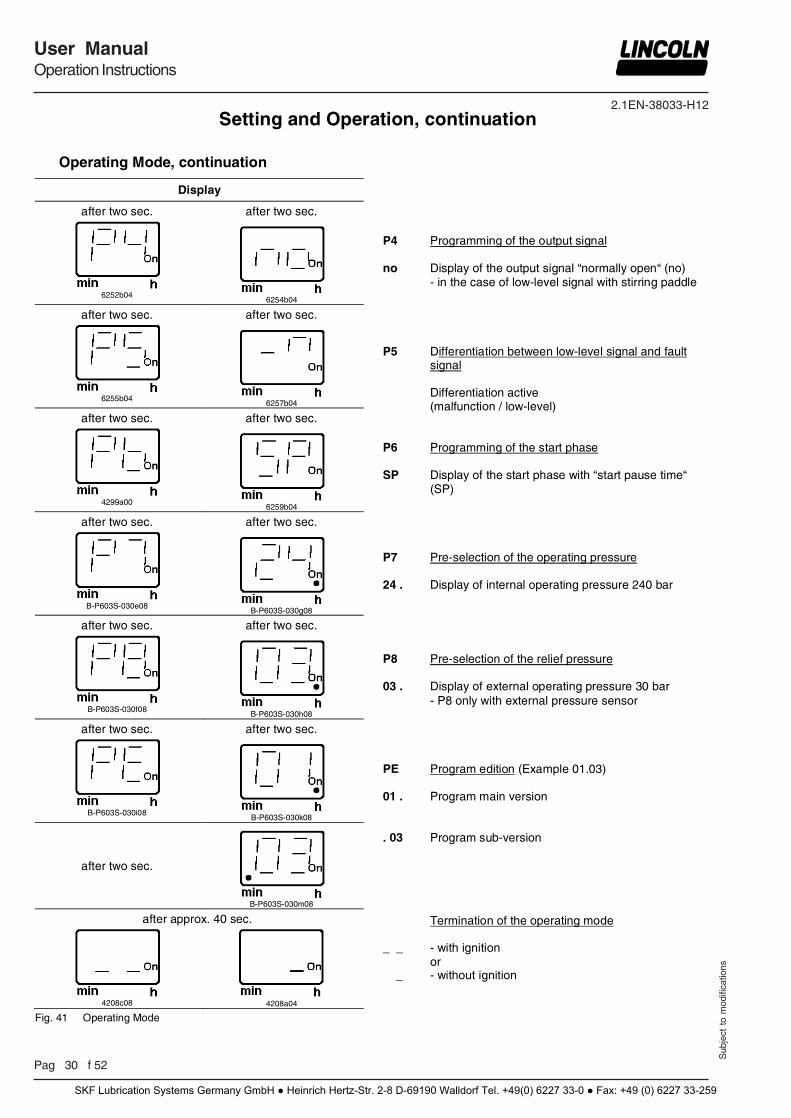
P4 Programming of the output signal no Display of the output signal “normally open“ (no) - in the case of low-level signal with stirring paddle P5 Differentiation between low-level signal and fault signal Differentiation active (malfunction / low-level) P6 Programming of the start phase SP Display of the start phase with “start pause time“ (SP) P7 Pre-selection of the operating pressure 24 . Display of internal operating pressure 240 bar P8 Pre-selection of the relief pressure 03 . Display of external operating pressure 30 bar - P8 only with external pressure sensor PE Program edition (Example 01.03) 01 . Program main version . 03 Program sub-version Termination of the operating mode _ _ - with ignition or _ - without ignition
Setting and Operation, continuation
SKF Lubrication Systems Germany GmbH ● Heinrich Hertz-Str. 2-8 D-69190 Walldorf Tel. +49(0) 6227 33-0 ● Fax: +49 (0) 6227 33-259
2.1EN-38033-H12
Sub
ject
to
mod
ifica
tions
User ManualOperation Instructions
P 31 f 52
6001a02
IMPORTANT
When filling the reservoir, vent bore A must not be closed: - in order to enable the escape of air - in order not to impede the proper suc-tion behaviour of the pump during opera-tion
6001a02
IMPORTANT
The grease or oil must be free from im-purities and must not be liable to change its consistency in the course of time.
1013A94
ATTENTION!
Risk of bursting if the reservoir is over-filled! When filling the reservoir by means of pumps with a large delivery volume do not exceed the max. filling mark.
6445b05
CAUTION!
Danger of squeezing in case of pumps to be filled from the reservoir top: Never put your hand into the open res-ervoir while pump is running!
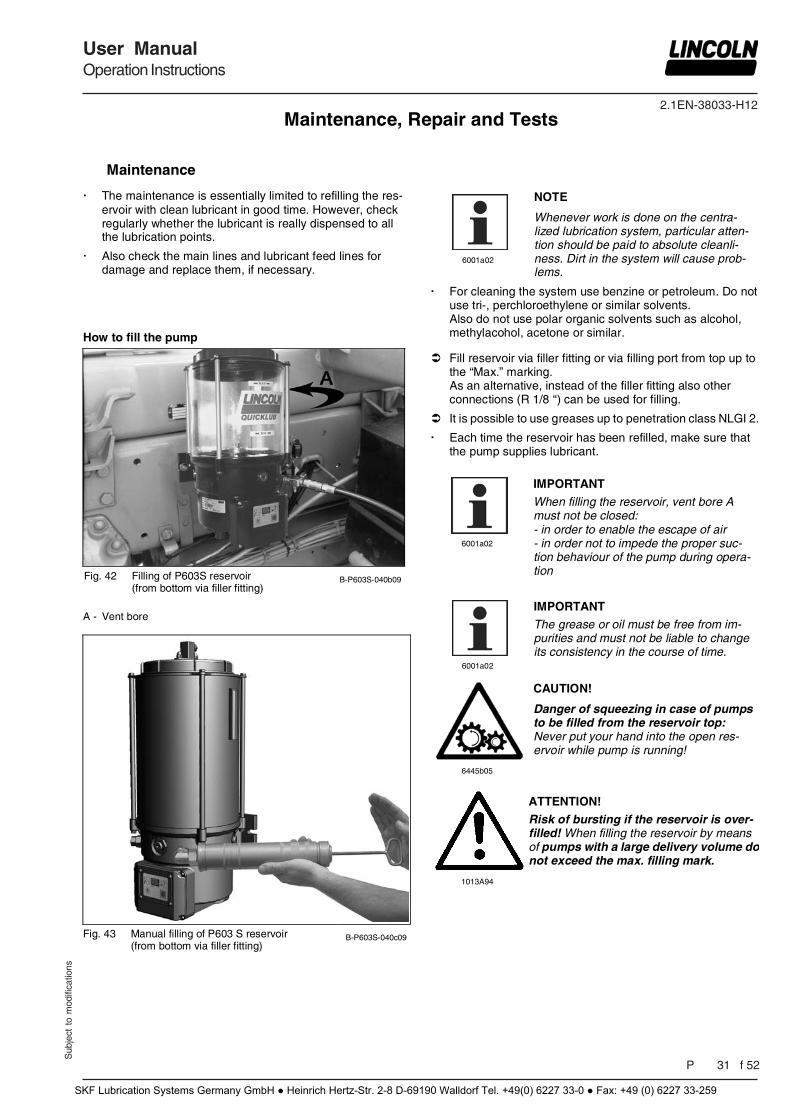
How to fill the pump
Fig. 42 Filling of P603S reservoir (from bottom via filler fitting)
B-P603S-040b09
A - Vent bore
Fig. 43 Manual filling of P603 S reservoir
(from bottom via filler fitting) B-P603S-040c09
Fill reservoir via filler fitting or via filling port from top up to the “Max.” marking. As an alternative, instead of the filler fitting also other connections (R 1/8 “) can be used for filling.
It is possible to use greases up to penetration class NLGI 2.
Each time the reservoir has been refilled, make sure that the pump supplies lubricant.
Maintenance, Repair and Tests
Maintenance
The maintenance is essentially limited to refilling the res-ervoir with clean lubricant in good time. However, check regularly whether the lubricant is really dispensed to all the lubrication points.
Also check the main lines and lubricant feed lines for damage and replace them, if necessary.
6001a02
NOTE
Whenever work is done on the centra-lized lubrication system, particular atten-tion should be paid to absolute cleanli-ness. Dirt in the system will cause prob-lems.
For cleaning the system use benzine or petroleum. Do not use tri-, perchloroethylene or similar solvents. Also do not use polar organic solvents such as alcohol, methylacohol, acetone or similar.
SKF Lubrication Systems Germany GmbH ● Heinrich Hertz-Str. 2-8 D-69190 Walldorf Tel. +49(0) 6227 33-0 ● Fax: +49 (0) 6227 33-259
2.1EN-38033-H12
Pag 32 f 52
User ManualOperation Instructions
Sub
ject
to
mod
ifica
tions
Maintenance and Repair, continuation
How to fill the pump, continuation
B-P603S-040d09
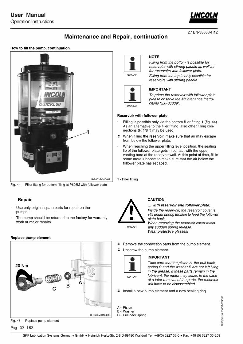
Fig. 44 Filler fitting for bottom filling at P603M with follower plate
6001a02
NOTE
Filling from the bottom is possible for reservoirs with stirring paddle as well as for reservoirs with follower plate. Filling from the top is only possible for reservoirs with stirring paddle.
6001a02
IMPORTANT
To prime the reservoir with follower plate please observe the Maintenance Instru-citons “2.0-38009“.
Reservoir with follower plate
Filling is possible only via the bottom filler fitting 1 (fig. 44). As an alternative to the filler fitting, also other filling con-nections (R 1/8 “) may be used.
When filling the reservoir, make sure that air may escape from below the follower plate:
When reaching the upper filling level position, the sealing lip of the follower plate gets in contact with the upper venting bore at the reservoir wall. At this point of time, fill in some more lubricant to make sure that the air below the follower plate has escaped.
1 - Filler fitting
Repair
Use only original spare parts for repair on the pumps.
The pump should be returned to the factory for warranty work or major repairs.
1013A94
CAUTION!
… with reservoir and follower plate: Inside the reservoir, the reservoir cover is still under spring tension to feed the follower plate back. When removing the reservoir cover avoid any sudden spring release. Wear protective glasses!
Replace pump element
B-P603M-040d08
Fig. 45 Replace pump element
Remove the connection parts from the pump element.
Unscrew the pump element.
6001a02
IMPORTANT
Take care that the piston A, the pull-back spring C and the washer B are not left lying in the grease. If these parts remain in the lubricant, the motor may seize. In the case of a later removal of the parts, the reservoir will have to be disassembled.
Install a new pump element and a new sealing ring. A - Piston B - Washer C - Pull-back spring
SKF Lubrication Systems Germany GmbH ● Heinrich Hertz-Str. 2-8 D-69190 Walldorf Tel. +49(0) 6227 33-0 ● Fax: +49 (0) 6227 33-259

2.1EN-38033-H12
Sub
ject
to
mod
ifica
tions
User ManualOperation Instructions
P 33 f 52
Electrical Connection
4273a00
WARNING! Before maintenance or repair of pumps switch off their power supply.
Consider the safety instructions (page 5 and 6)!
CAUTION!
Before starting, make sure that the general power supply is off. The device must never be connected or disconnected when the power is on. The protective conductor must always be connected. Take care that this line section is undamaged and conforms to standards and the contacts are safe.
6001a02
NOTE
The protection IP6K9K is guaranteed when the socket (X1:, X2: & X3:) is tightened on the housing cover with flat packing.
NOTE Consider the contact protection measures for connecting the high- or low-level control (see chapter “Mode of Operation” / para-graph „Low- or High-level Control”).
Make sure of the connection and the type of construction
of your pump. - type of connection (VDC / VAC) - low-level indication - type of connection plug
Connect the electrical wires according to the following electrical connecting diagrams (see chapter „Technical Data“).
Operation with bayonet plug
4273a00
CAUTION!
If the protective-conductor terminal is not connected or interrupted, dangerous touch voltages may occur on the equipment!
Protective measures to be applied for appropriate operation with bayonet plugs: "Functional extra-low voltage with safe isolation" / "Protective Extra-Low Voltage" (PELV) Standards: DIN EN 60204 Part 1: 2007-07 / IEC 204-1 / DIN VDE 0100 Part 410: 2007-06 / IEC 364-4-41
Maintenance and Repair, continuation
4273a00
ATTENTION!
Control p.c.b. and motor always work with 24 VDC even if the pump is connected to alternating current. Consider residual ripple of max. 5 % when connecting motor and control p.c.b. (in relation to the operating voltage acc. to DIN 41755).
Replace Printed Circuit Boards
Note all jumper positions of the defective p.c.b. (comp. chapter “Jumper Configuration”).
Defective printed circuit boards should be suitably packed and returned to the factory.
With substitution of a p.c.b. the type S00/B00 (see chapter “Jumper Configuration”) is always delivered.
Configure at the new p.c.b. the noted jumper positions of the old p.c.b.
SKF Lubrication Systems Germany GmbH ● Heinrich Hertz-Str. 2-8 D-69190 Walldorf Tel. +49(0) 6227 33-0 ● Fax: +49 (0) 6227 33-259
2.1EN-38033-H12
Pag 34 f 52
User ManualOperation Instructions
Sub
ject
to
mod
ifica
tions
Maintenance, Repair and Tests, continuation
To Check the Pressure Relief Valve
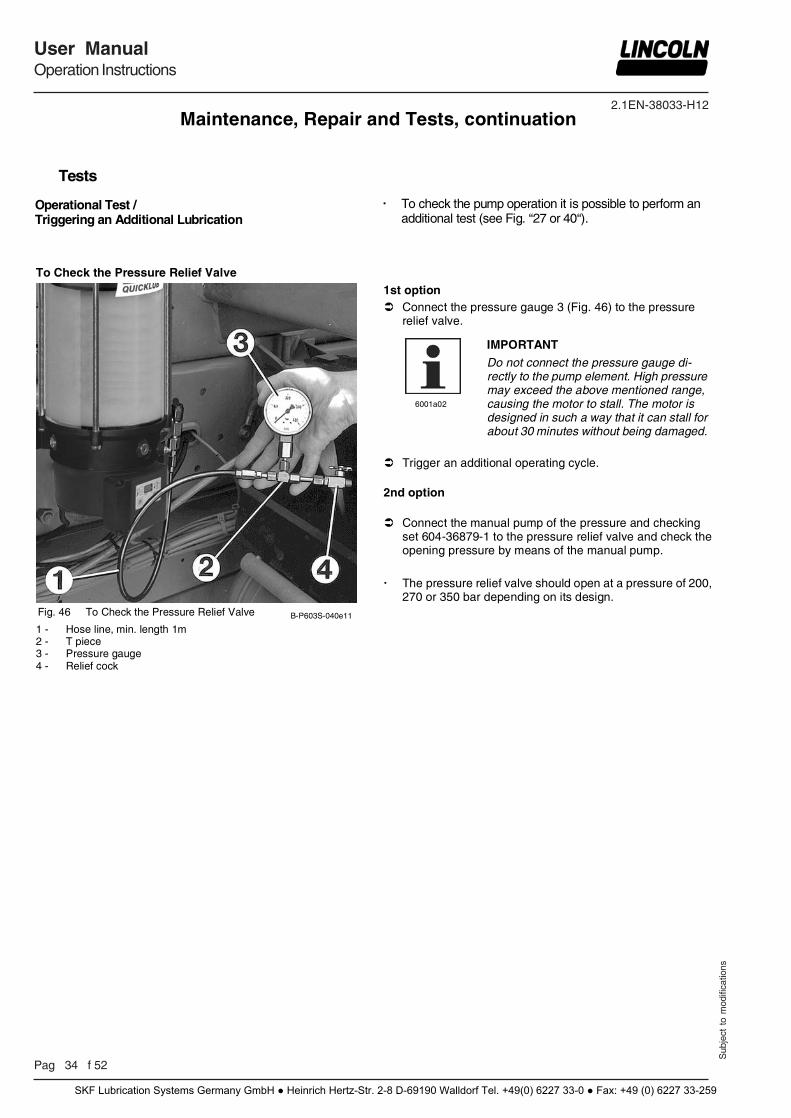
Fig. 46 To Check the Pressure Relief Valve B-P603S-040e11
1 - Hose line, min. length 1m 2 - T piece 3 - Pressure gauge 4 - Relief cock
1st option Connect the pressure gauge 3 (Fig. 46) to the pressure
relief valve.
6001a02
IMPORTANT
Do not connect the pressure gauge di-rectly to the pump element. High pressure may exceed the above mentioned range, causing the motor to stall. The motor is designed in such a way that it can stall for about 30 minutes without being damaged.
Trigger an additional operating cycle. 2nd option Connect the manual pump of the pressure and checking
set 604-36879-1 to the pressure relief valve and check the opening pressure by means of the manual pump.
The pressure relief valve should open at a pressure of 200,
270 or 350 bar depending on its design.
Tests
Operational Test / Triggering an Additional Lubrication
To check the pump operation it is possible to perform an additional test (see Fig. “27 or 40“).
SKF Lubrication Systems Germany GmbH ● Heinrich Hertz-Str. 2-8 D-69190 Walldorf Tel. +49(0) 6227 33-0 ● Fax: +49 (0) 6227 33-259
2.1EN-38033-H12
Sub
ject
to
mod
ifica
tions
User ManualOperation Instructions
P 35 f 52
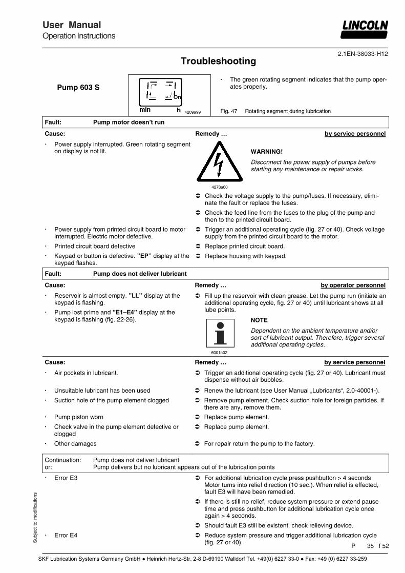
Pump 603 S
4209a99
The green rotating segment indicates that the pump oper-ates properly.
Fig. 47 Rotating segment during lubrication
Fault: Pump motor doesn’t run
Cause: Remedy … by service personnel
Power supply interrupted. Green rotating segment on display is not lit.
4273a00
WARNING!
Disconnect the power supply of pumps before starting any maintenance or repair works.
Check the voltage supply to the pump/fuses. If necessary, elimi-nate the fault or replace the fuses.
Check the feed line from the fuses to the plug of the pump and then to the printed circuit board.
Power supply from printed circuit board to motor interrupted. Electric motor defective.
Trigger an additional operating cycle (fig. 27 or 40). Check voltage supply from the printed circuit board to the motor.
Printed circuit board defective Replace printed circuit board.
Keypad or button is defective. ”EP” display at the keypad flashes.
Replace housing with keypad.
Fault: Pump does not deliver lubricant
Cause: Remedy … by operator personnel
Reservoir is almost empty. ”LL” display at the keypad is flashing.
Pump lost prime and ”E1–E4” display at the keypad is flashing (fig. 22-26).
Fill up the reservoir with clean grease. Let the pump run (initiate an additional operating cycle, fig. 27 or 40) until lubricant shows at all lube points.
6001a02
NOTE
Dependent on the ambient temperature and/or sort of lubricant output. Therefore, trigger several additional operating cycles.
Cause: Remedy … by service personnel
Air pockets in lubricant. Trigger an additional operating cycle (fig. 27 or 40). Lubricant must dispense without air bubbles.
Continuation: Pump does not deliver lubricant or: Pump delivers but no lubricant appears out of the lubrication points
Error E3 For additional lubrication cycle press pushbutton > 4 seconds Motor turns into relief direction (10 sec.). When relief is effected, fault E3 will have been remedied.
If there is still no relief, reduce system pressure or extend pause time and press pushbutton for additional lubrication cycle once again > 4 seconds.
Should fault E3 still be existent, check relieving device.
Error E4 Reduce system pressure and trigger additional lubrication cycle (fig. 27 or 40).
Troubleshooting
Unsuitable lubricant has been used Renew the lubricant (see User Manual „Lubricants“, 2.0-40001-).
Suction hole of the pump element clogged Remove pump element. Check suction hole for foreign particles. If there are any, remove them.
Pump piston worn Replace pump element.
Check valve in the pump element defective or clogged
Replace pump element.
Other damages For repair return the pump to the factory.
SKF Lubrication Systems Germany GmbH ● Heinrich Hertz-Str. 2-8 D-69190 Walldorf Tel. +49(0) 6227 33-0 ● Fax: +49 (0) 6227 33-259
2.1EN-38033-H12
Pag 36 f 52
User ManualOperation Instructions
Sub
ject
to
mod
ifica
tions
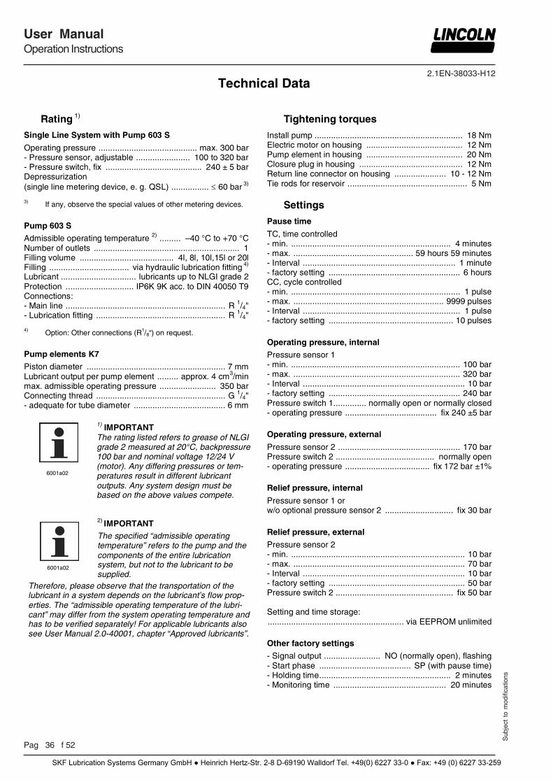
Rating 1)
Single Line System with Pump 603 S
Operating pressure .......................................... max. 300 bar - Pressure sensor, adjustable ....................... 100 to 320 bar - Pressure switch, fix ......................................... 240 ± 5 bar
Depressurization (single line metering device, e. g. QSL) ................ 60 bar 3)
3) If any, observe the special values of other metering devices.
Pump 603 S
Admissible operating temperature 2) ......... –40 °C to +70 °C Number of outlets .............................................................. 1 Filling volume ........................................ 4l, 8l, 10l,15l or 20l Filling .................................. via hydraulic lubrication fitting 4) Lubricant ................................ lubricants up to NLGI grade 2 Protection ............................. IP6K 9K acc. to DIN 40050 T9 Connections: - Main line .................................................................... R 1/4" - Lubrication fitting ....................................................... R 1/4"
4) Option: Other connections (R1/8“) on request. Pump elements K7
Piston diameter ........................................................... 7 mm Lubricant output per pump element ......... approx. 4 cm3/min max. admissible operating pressure ........................ 350 bar Connecting thread ....................................................... G 1/4" - adequate for tube diameter ....................................... 6 mm
Tightening torques
Install pump ............................................................... 18 Nm Electric motor on housing ......................................... 12 Nm Pump element in housing ......................................... 20 Nm Closure plug in housing ............................................ 12 Nm Return line connector on housing ...................... 10 - 12 Nm Tie rods for reservoir ................................................... 5 Nm
Settings
Pause time
TC, time controlled - min. .................................................................... 4 minutes - max. ................................................... 59 hours 59 minutes - Interval ................................................................. 1 minute - factory setting ........................................................ 6 hours CC, cycle controlled - min. ........................................................................ 1 pulse - max. ................................................................ 9999 pulses - Interval ................................................................... 1 pulse - factory setting ..................................................... 10 pulses
Operating pressure, internal
Pressure sensor 1 - min. ........................................................................ 100 bar - max. ....................................................................... 320 bar - Interval ..................................................................... 10 bar - factory setting ........................................................ 240 bar Pressure switch 1 .............. normally open or normally closed - operating pressure ....................................... fix 240 ±5 bar
Operating pressure, external
Pressure sensor 2 .................................................... 170 bar Pressure switch 2 .......................................... normally open - operating pressure .................................... fix 172 bar ±1% Relief pressure, internal
Pressure sensor 1 or w/o optional pressure sensor 2 ............................. fix 30 bar
Relief pressure, external
Pressure sensor 2 - min. .......................................................................... 10 bar - max. ......................................................................... 70 bar - Interval ..................................................................... 10 bar - factory setting .......................................................... 50 bar Pressure switch 2 .................................................. fix 50 bar Setting and time storage: .......................................................... via EEPROM unlimited
Other factory settings
- Signal output ........................ NO (normally open), flashing - Start phase ....................................... SP (with pause time) - Holding time ........................................................ 2 minutes - Monitoring time ................................................ 20 minutes
6001a02
1) IMPORTANT The rating listed refers to grease of NLGI grade 2 measured at 20°C, backpressure 100 bar and nominal voltage 12/24 V (motor). Any differing pressures or tem-peratures result in different lubricant outputs. Any system design must be based on the above values compete.
6001a02
2) IMPORTANT The specified “admissible operating temperature” refers to the pump and the components of the entire lubrication system, but not to the lubricant to be supplied.
Therefore, please observe that the transportation of the lubricant in a system depends on the lubricant’s flow prop-erties. The “admissible operating temperature of the lubri-cant” may differ from the system operating temperature and has to be verified separately! For applicable lubricants also see User Manual 2.0-40001, chapter “Approved lubricants”.
Technical Data
SKF Lubrication Systems Germany GmbH ● Heinrich Hertz-Str. 2-8 D-69190 Walldorf Tel. +49(0) 6227 33-0 ● Fax: +49 (0) 6227 33-259
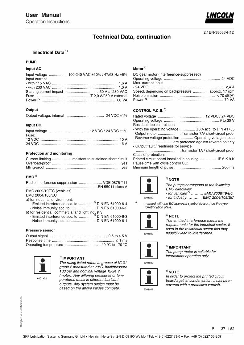
2.1EN-38033-H12
Sub
ject
to
mod
ifica
tions
User ManualOperation Instructions
P 37 f 52
Electrical Data 1)
PUMP
Input AC
Input voltage ................. 100-240 VAC 10% ; 47/63 Hz 5% Input current - with 115 VAC ............................................................... 1,6 A - with 230 VAC ............................................................... 1,0 A Starting current impact ................................ 50 A at 230 VAC Fuse .................................................... T 2,0 A/250 V external Power P ....................................................................... 60 VA
Output
Output voltage, internal ..................................... 24 VDC 1% Input DC
Input voltage ...................................... 12 VDC / 24 VDC 1% Fuse: 12 VDC ........................................................................... 10 A 24 VDC ............................................................................. 6 A
Protection and monitoring
Current limiting .................. resistant to sustained short circuit Overload-proof ................................................................. yes Idling-proof ....................................................................... yes
EMC 2)
Radio interference suppression ...................... VDE 0875 T11 ..................................................................... EN 55011 class A EMC 2009/19/EC (vehicles) EMC 2004/108/EC a) for industrial environment: - Emitted interference acc. to ............. 3) DIN EN 61000-6-4 - Noise immunity acc. to ........................ DIN EN 61000-6-2 b) for residential, commercial and light industry: - Emitted interference acc. to ............. 3) DIN EN 61000-6-3 - Noise immunity acc. to ........................ DIN EN 61000-6-1 Pressure sensor
Output signal ........................................................ 0.5 to 4.5 V Response time ............................................................ 1 ms Operating temperature ................................ –40 °C to +70 °C
Motor 4)
DC gear motor (interference-suppressed) Operating voltage ...................................................... 24 VDC Max. current input - 24 VDC ........................................................................ 2,4 A Speed, depending on backpressure ............... approx. 17 rpm Noise emission ..................................................... < 70 dB(A) Power P ........................................................................ 72 VA
CONTROL P.C.B. 5)
Rated voltage ............................................. 12 VDC / 24 VDC Operating voltage ..................................................... 9 to 30 V Residual ripple in relation - With the operating voltage ............... 5% acc. to DIN 41755 Output motor ...................... Transistor 7A/ short-circuit proof Reverse voltage protection ............ Operating voltage inputs ...................................... are protected against reverse polarity - Output fault / readiness for service ............................................ transistor 1A / short-circuit proof Class of protection: Printed circuit board installed in housing ............... IP 6 K 9 K Pause time with cycle control CC: Minimum length of pulse ............................................. 200 ms
6001a02
4) IMPORTANT The pump motor is suitable for intermittent operation only.
6001a02
3) NOTE The emitted interference meets the requirements for the industrial sector, if used in the residential sector this may possibly lead to interference.
6001a02
2) NOTE The pumps correspond to the following EMC directives: - for vehicles A) ………. EMC 2009/19/EC - for industry ………... EMC 2004/108/EC
A) marked with the EC approval symbol (e-icon) on the type identification plate.
6001a02
1) IMPORTANT The rating listed refers to grease of NLGI grade 2 measured at 20°C, backpressure 100 bar and nominal voltage 12/24 V (motor). Any differing pressures or tem-peratures result in different lubricant outputs. Any system design must be based on the above values compete.
6001a02
5) NOTE In order to protect the printed circuit board against condensation, it has been covered with a protective varnish.
Technical Data, continuation
SKF Lubrication Systems Germany GmbH ● Heinrich Hertz-Str. 2-8 D-69190 Walldorf Tel. +49(0) 6227 33-0 ● Fax: +49 (0) 6227 33-259
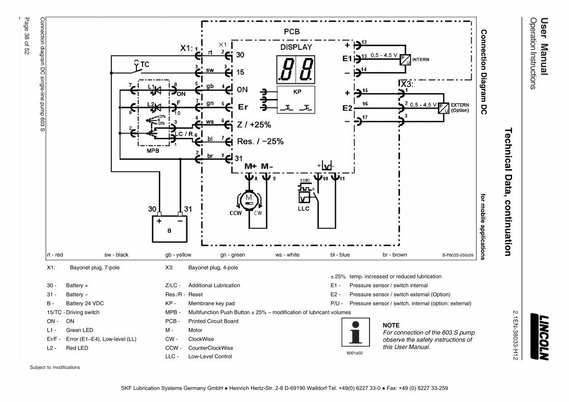
2.1EN
-38033-H12
Page 38 of 52
User M
anu
alO
peration Instructions
Subject to modifications
Co
nn
ection
Diag
ram D
C
for m
ob
ile app
lication
s
B-P603S-050c09
± 25% temp. increased or reduced lubrication
E1 - Pressure sensor / switch internal
E2 - Pressure sensor / switch external (Option)
P/U - Pressure sensor / switch, internal (option: external)
MPB - Multifunction Push Button ± 25% – modification of lubricant volumes
NOTE For connection of the 603 S pump observe the safety instructions of this User Manual.
br - brown bl - blue
6001a02
ws - white
X3: Bayonet plug, 4-pole
Z/LC - Additional Lubrication
Res./R - Reset
KP - Membrane key pad
PCB - Printed Circuit Board
M - Motor
CW - ClockWise
CCW - CounterClockWise
LLC - Low-Level Control
gn - green gb - yellow sw - black
X1: Bayonet plug, 7-pole
30 - Battery +
31 - Battery –
B - Battery 24 VDC
15/TC - Driving switch
ON - ON
L1 - Green LED
Er/F - Error (E1–E4), Low-level (LL)
L2 - Red LED
rt - red
Connection diagram
DC
single-line pump 603 S
Tech
nical D
ata, con
tinu
ation
SKF Lubrication Systems Germany GmbH ● Heinrich Hertz-Str. 2-8 D-69190 Walldorf Tel. +49(0) 6227 33-0 ● Fax: +49 (0) 6227 33-259
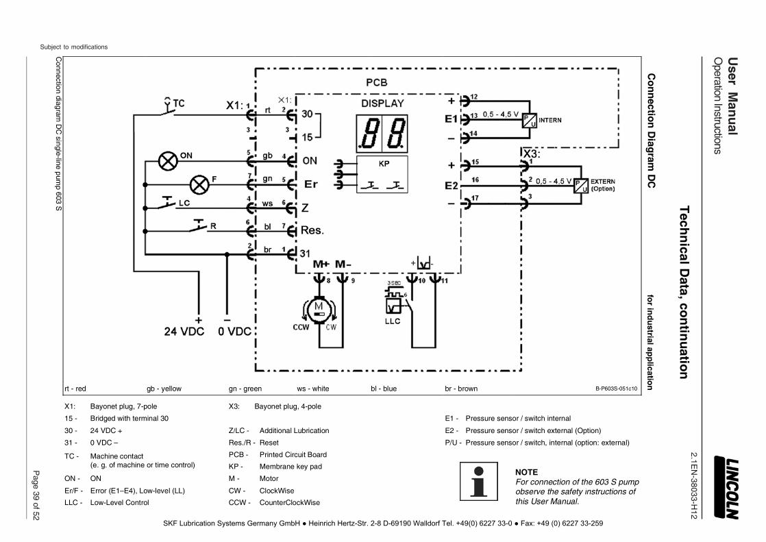
2.1EN
-38033-H12
Subject to modifications
User M
anu
alO
peration Instructions
Page 39 of 52
Co
nn
ection
Diag
ram D
C
for in
du
strial app
lication
B-P603S-051c10
E1 - Pressure sensor / switch internal
E2 - Pressure sensor / switch external (Option)
P/U - Pressure sensor / switch, internal (option: external)
PCB - Printed Circuit Board
NOTE For connection of the 603 S pump observe the safety instructions of this User Manual.
br - brown
bl - blue X3: Bayonet plug, 4-pole
Z/LC - Additional Lubrication
Res./R - Reset
KP - Membrane key pad
M - Motor
CW - ClockWise
CCW - CounterClockWise
ws - white gn - green gb - yellow X1: Bayonet plug, 7-pole
15 - Bridged with terminal 30
30 - 24 VDC +
31 - 0 VDC –
TC - Machine contact (e. g. of machine or time control)
ON - ON
Er/F - Error (E1–E4), Low-level (LL)
LLC - Low-Level Control
rt - red
Connection diagram
DC
single-line pump 603 S
Tech
nical D
ata, con
tinu
ation
SKF Lubrication Systems Germany GmbH ● Heinrich Hertz-Str. 2-8 D-69190 Walldorf Tel. +49(0) 6227 33-0 ● Fax: +49 (0) 6227 33-259
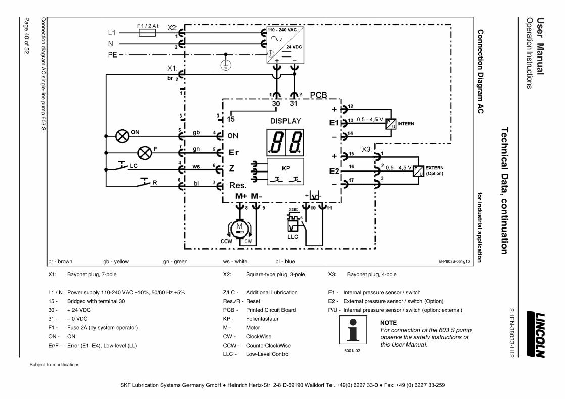
2.1EN
-38033-H12
Page 40 of 52
User M
anu
alO
peration Instructions
Subject to modifications
Co
nn
ection
Diag
ram A
C
for in
du
strial app
lication
B-P603S-051g10
X3: Bayonet plug, 4-pole
E1 - Internal pressure sensor / switch
E2 - External pressure sensor / switch (Option)
P/U - Internal pressure sensor / switch (option: external)
NOTE For connection of the 603 S pump observe the safety instructions of this User Manual.
6001a02
bl - blue X2: Square-type plug, 3-pole
Z/LC - Additional Lubrication
Res./R - Reset
PCB - Printed Circuit Board
KP - Folientastatur
M - Motor
CW - ClockWise
CCW - CounterClockWise
LLC - Low-Level Control
ws - white gn - green X1: Bayonet plug, 7-pole
L1 / N Power supply 110-240 VAC ±10%, 50/60 Hz ±5%
15 - Bridged with terminal 30
30 - + 24 VDC
31 - – 0 VDC
F1 - Fuse 2A (by system operator)
ON - ON
Er/F - Error (E1–E4), Low-level (LL)
gb - yellow br - brown
Connection diagram
AC
single-line pump 603 S
Tech
nical D
ata, con
tinu
ation
SKF Lubrication Systems Germany GmbH ● Heinrich Hertz-Str. 2-8 D-69190 Walldorf Tel. +49(0) 6227 33-0 ● Fax: +49 (0) 6227 33-259
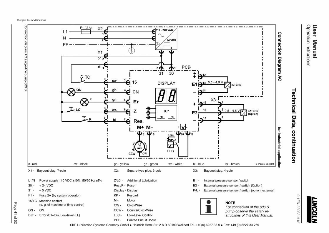
2.1EN
-38033-H12
Subject to modifications
User M
anu
alO
peration Instructions
Page 41 of 52
Tech
nical D
ata, con
tinu
ation
Co
nn
ection
Diag
ram A
C
for in
du
strial applicatio
n
B-P603S-051g09
X3: Bayonet plug, 4-pole
E1 - Internal pressure sensor / switch
E2 - External pressure sensor / switch (Option)
P/U - External pressure sensor / switch (option: external)
KP - Keypad
NOTE For connection of the 603 S pump observe the safety in-structions of this User Manual.
br - brown bl - blue
ws - white
X2: Square-type plug, 3-pole
Z/LC - Additional Lubrication
Res./R - Reset
Display - Display
M - Motor
CW - ClockWise
CCW - CounterClockWise
LLC - Low-Level Control
PCB Printed Circuit Board
gn - green gb - yellow sw - black
X1 - Bayoent plug, 7-pole
L1/N Power supply 110 VDC ±10%, 50/60 Hz ±5%
30 - + 24 VDC
31 - – 0 VDC
F1 - Fuse 2A (by system operator)
15/TC - Machine contact (e. g. of machine or time control)
ON - ON
Er/F - Error (E1–E4), Low-level (LL)
rt -red
Connection diagram
AC
single-line pump 603 S
SKF Lubrication Systems Germany GmbH ● Heinrich Hertz-Str. 2-8 D-69190 Walldorf Tel. +49(0) 6227 33-0 ● Fax: +49 (0) 6227 33-259
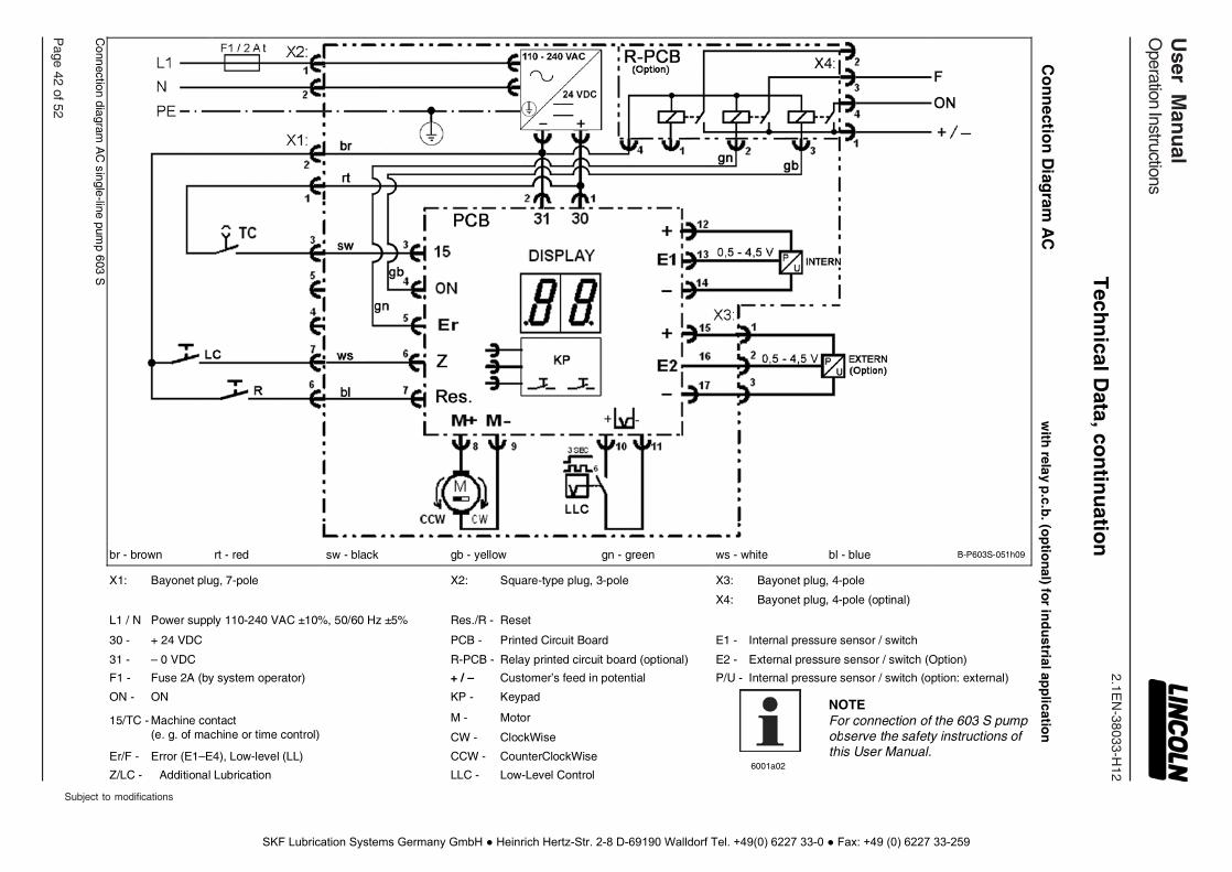
2.1EN
-38033-H12
Page 42 of 52
User M
anu
alO
peration Instructions
Subject to modifications
Co
nn
ection
Diag
ram A
C
with
relay p.c.b
. (op
tional) for in
du
strial app
lication
B-P603S-051h09
X3: Bayonet plug, 4-pole
X4: Bayonet plug, 4-pole (optinal)
E1 - Internal pressure sensor / switch
E2 - External pressure sensor / switch (Option)
P/U - Internal pressure sensor / switch (option: external)
NOTE For connection of the 603 S pump observe the safety instructions of this User Manual.
bl - blue ws - white
6001a02
gn - green X2: Square-type plug, 3-pole
Res./R - Reset
PCB - Printed Circuit Board
R-PCB - Relay printed circuit board (optional)
+ / – Customer’s feed in potential
KP - Keypad
M - Motor
CW - ClockWise
CCW - CounterClockWise
LLC - Low-Level Control
gb - yellow sw - black X1: Bayonet plug, 7-pole
L1 / N Power supply 110-240 VAC ±10%, 50/60 Hz ±5%
30 - + 24 VDC
31 - – 0 VDC
F1 - Fuse 2A (by system operator)
ON - ON
15/TC - Machine contact (e. g. of machine or time control)
Er/F - Error (E1–E4), Low-level (LL)
Z/LC - Additional Lubrication
rt - red br - brown
Connection diagram
AC
single-line pump 603 S
Tech
nical D
ata, con
tinu
ation
SKF Lubrication Systems Germany GmbH ● Heinrich Hertz-Str. 2-8 D-69190 Walldorf Tel. +49(0) 6227 33-0 ● Fax: +49 (0) 6227 33-259

2.1EN-38033-H12
Sub
ject
to
mod
ifica
tions
User ManualOperation Instructions
P 43 f 52
Schematic of Single-line Pump 603 S
B-P603S-051k09
Fig. 46 Schematic of Single-line Pump 603 S
1 - Single-line pump 603 S 2 - Reservoir 3 - Motor with moving direction counterclockwise and clockwise 4 - Low-level control 5 - Control p.c.b. 6 - Single-line metering device (QSL) 7a - Internal pressure sensor
- Operating pressure, adjustable .…………..… 100 … 320 bar - Relief pressure ………………….…………………... 30 bar, fix Internal pressure switch ………………………….. normally open - Operating pressure ………………………….... 240 ±5 bar, fix
7b - Option: External pressure sensor - Operating pressure …………..…………………… 170 bar, fix - Relief pressure, adjustable ……………………... 10 … 70 bar External pressure switch ………………………… normally open - Operating pressure ……………………………..... 172 bar, fix
8 - Membrane key-pad 9 - Display 10 - Pump A - Power supply B - Start C - Alarm contact / signals D - Relay control (option)
Identification Code, continuation
Decoding: Electric connecting possibilities 3)
… for power supply 12 VDC or 24 VDC:
Power supply
VDC Low-level (LL) &
Error indication (Er) Pressure switch or Pressure sensor 4)
Relay control (optionally for LL & Er)
Typ
e o
f co
nn
ectio
n 1A7.16 Bayonet plug 7-pole, left
2A7.16 Bayonet plug 7-pole, left Bayonet plug 4/3-pole, right
2B7.16 Bayonet plug 7-pole, left Bayonet plug 4-pole, right
3A7.16 Bayonet plug 7-pole, left Bayonet plug 4/3-pole, right Bayonet plug 4-pole, right
… for power supply 110 – 240 VAC:
Power supply VAC Low-level (LL) & Error indication (Er)
Pressure switch or Pressure sensor 4)
Relay control (optionally for LL & Er)
Coupling relay (prompt via 2 or
3 relays)
Typ
e o
f co
nne
ctio
n
2A1.01 Square-type plug, left Bayonet plug 7-pole, left
2B1.01 Square-type plug, left Bayonet plug 4-pole, right
3A1.01 Square-type plug, left Bayonet plug 7-pole, left Bayonet plug 4/3-pole, right
3B1.01 8) Square-type plug, left Bayonet plug 7-pole, left Bayonet plug 4-pole, right
3C1.01 Square-type plug, left Bayonet plug 4/3-pole, right
Bayonet plug 4-pole, right
4A1.01 9) Square-type plug, left Bayonet plug 7-pole, left Bayonet plug 4/3-pole, right
Bayonet plug 4-pole, right
2D1.01 Square-type plug, left M12 plug, 4-pole right
3) see „Connection Diagrams“
4) incl. 10 m cable (4-wire); precondition: jumper position “2S” (see chapter “Jumper Configuration”)
8) Precondition: Pump with control p.c.b. model S 9) Precondition: Pump with internal pressure switch
Technical Data, continuation
SKF Lubrication Systems Germany GmbH ● Heinrich Hertz-Str. 2-8 D-69190 Walldorf Tel. +49(0) 6227 33-0 ● Fax: +49 (0) 6227 33-259
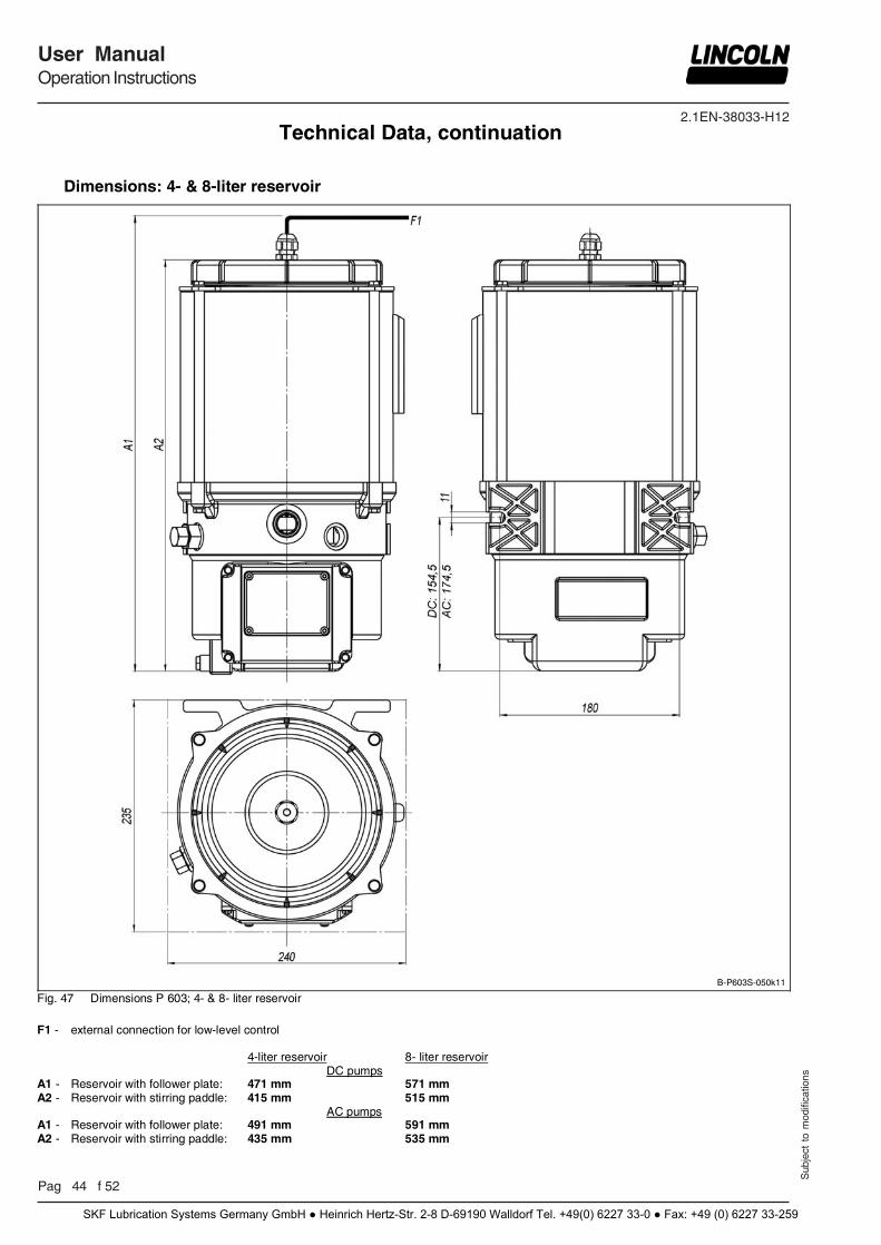
2.1EN-38033-H12
Pag 44 f 52
User ManualOperation Instructions
Sub
ject
to
mod
ifica
tions
Dimensions: 4- & 8-liter reservoir
B-P603S-050k11
Fig. 47 Dimensions P 603; 4- & 8- liter reservoir
F1 - external connection for low-level control 4-liter reservoir 8- liter reservoir DC pumps A1 - Reservoir with follower plate: 471 mm 571 mm A2 - Reservoir with stirring paddle: 415 mm 515 mm AC pumps A1 - Reservoir with follower plate: 491 mm 591 mm A2 - Reservoir with stirring paddle: 435 mm 535 mm
Technical Data, continuation
SKF Lubrication Systems Germany GmbH ● Heinrich Hertz-Str. 2-8 D-69190 Walldorf Tel. +49(0) 6227 33-0 ● Fax: +49 (0) 6227 33-259
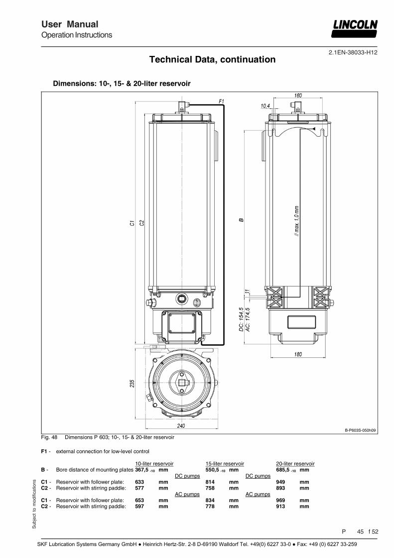
2.1EN-38033-H12
Sub
ject
to
mod
ifica
tions
User ManualOperation Instructions
P 45 f 52
Dimensions: 10-, 15- & 20-liter reservoir
B-P603S-050h09
Fig. 48 Dimensions P 603; 10-, 15- & 20-liter reservoir
F1 - external connection for low-level control 10-liter reservoir 15-liter reservoir 20-liter reservoir B - Bore distance of mounting plates 367,5 -10 mm 550,5 -10 mm 685,5 -10 mm DC pumps DC pumps C1 - Reservoir with follower plate: 633 mm 814 mm 949 mm C2 - Reservoir with stirring paddle: 577 mm 758 mm 893 mm AC pumps AC pumps C1 - Reservoir with follower plate: 653 mm 834 mm 969 mm C2 - Reservoir with stirring paddle: 597 mm 778 mm 913 mm
Technical Data, continuation
SKF Lubrication Systems Germany GmbH ● Heinrich Hertz-Str. 2-8 D-69190 Walldorf Tel. +49(0) 6227 33-0 ● Fax: +49 (0) 6227 33-259
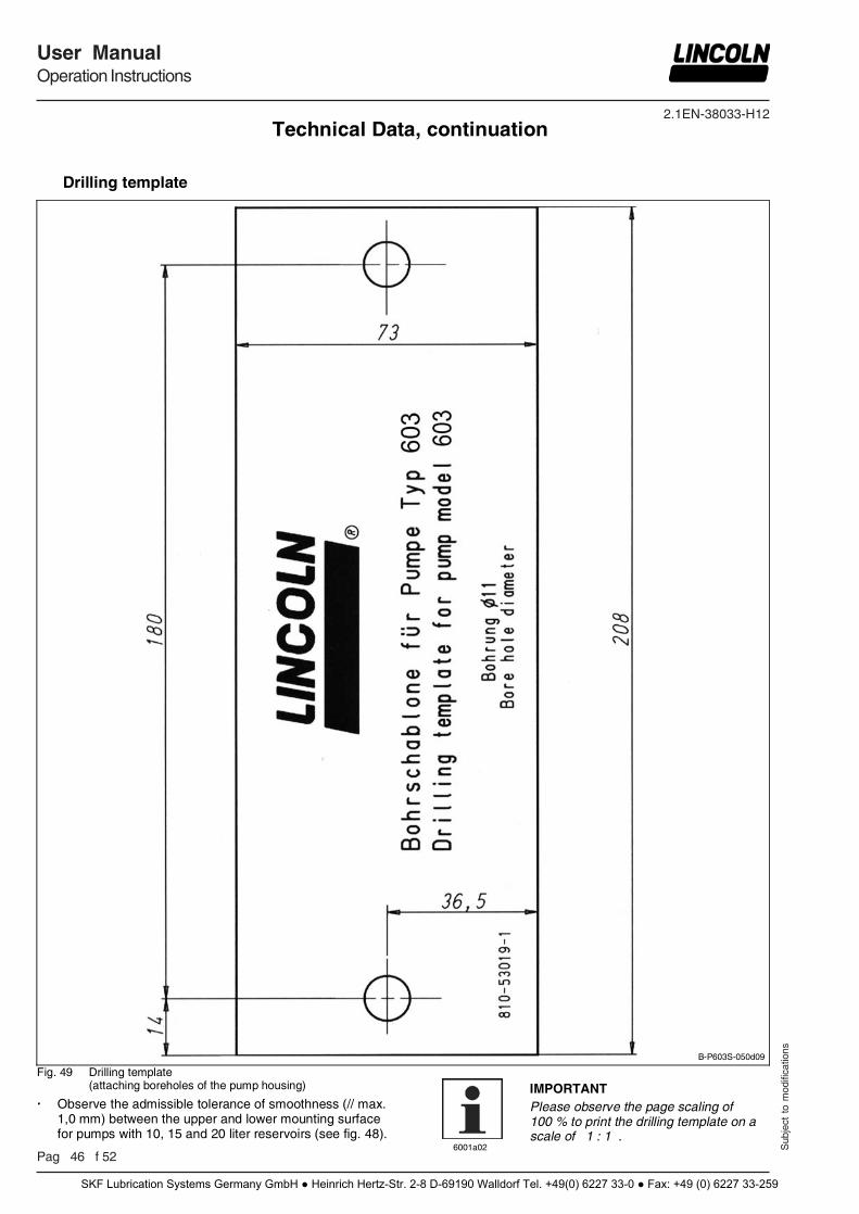
2.1EN-38033-H12
Pag 46 f 52
User ManualOperation Instructions
Sub
ject
to
mod
ifica
tions
Drilling template
B-P603S-050d09
Fig. 49 Drilling template (attaching boreholes of the pump housing)
Observe the admissible tolerance of smoothness (// max. 1,0 mm) between the upper and lower mounting surface for pumps with 10, 15 and 20 liter reservoirs (see fig. 48).
6001a02
IMPORTANT Please observe the page scaling of 100 % to print the drilling template on a scale of 1 : 1 .
Technical Data, continuation
SKF Lubrication Systems Germany GmbH ● Heinrich Hertz-Str. 2-8 D-69190 Walldorf Tel. +49(0) 6227 33-0 ● Fax: +49 (0) 6227 33-259
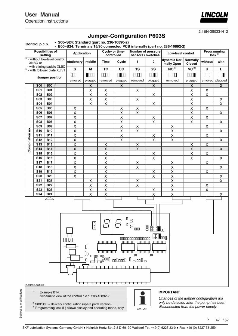
2.1EN-38033-H12
Sub
ject
to
mod
ifica
tions
User ManualOperation Instructions
P 47 f 52
Jumper-Configuration P603S Control p.c.b. - S00–S24: Standard (part no. 236-10890-2)
- B00–B24: Terminals 15/30 connected PCB internally (part no. 236-10892-2) Possibilities of
setting Application Cycle- or time- controlled
Number of pressure sensors / switches Low-level control Programming
lock 3) a) - without low-level control XNBO or - with stirring paddle XLBO
b) - with follower plate XLF/1
stationary mobile Time Cycle 1 2 dynamic Nor-mally Open
Normally Closed
without with
S M TC CC 1S 2S NO a) NC b) U L
Jumper position removed plugged removed plugged removed plugged removed plugged removed plugged
Co
mb
inat
ion
no
.
S00 B00 2) X X X X X S01 B01 X X X X X S02 B02 X X X X X S03 B03 X X X X X S04 B04 X X X X X S05 B05 X X X X X S06 B06 X X X X X S07 B07 X X X X X S08 B08 X X X X X S09 B09 X X X X X S10 B10 X X X X X S11 B11 X X X X X S12 B12 X X X X X S13 B13 X X X X X S14 B14 1) X X X X X S15 B15 X X X X X S16 B16 X X X X X S17 B17 X X X X X S18 B18 X X X X X S19 B19 X X X X X S20 B20 X X X X X S21 B21 X X X X X S22 B22 X X X X X S23 B23 X X X X X S24 B24 X X X X X
B-P653S-060o09
1) Example B14: Schematic view of the control p.c.b. 236-10892-2
6001a02
IMPORTANT
Changes of the jumper configuration will only be detected after the pump has been disconnected from the power supply.
2) S00/B00 = delivery configuration (spare parts version) 3) Programming lock (L) allows display and operating mode, only.
SKF Lubrication Systems Germany GmbH ● Heinrich Hertz-Str. 2-8 D-69190 Walldorf Tel. +49(0) 6227 33-0 ● Fax: +49 (0) 6227 33-259
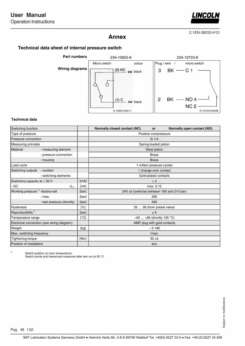
2.1EN-38033-H12
Pag 48 f 52
User ManualOperation Instructions
Sub
ject
to
mod
ifica
tions
Annex
Technical data sheet of internal pressure switch
Part numbers 234-10922-6 234-10723-8 Micro switch colour Plug / wire / micro switch
Wiring diagrams
D-10922-040c11
black
D-10723-040o08
black
Technical data
Switching function Normally closed contact (NC) or Normally open contact (NO)
Type of pressure Positive overpressure
Pressure connection G 1/4
Measuring principle Spring-loaded piston
Material - measuring element Steel piston
- pressure connection Brass
- housing Brass
Load cycle 1 million pressure cycles
Switching outputs - number 1 change-over contact
- switching elements Gold-plated contacts
Switching capacity at 30 V [mA] 4
- DC U xl [VA] max. 0.12
Working pressure 1) -factory-set [bar] 240 ±5 (switches between 160 and 210 bar)
- max. [bar] 300
- test pressure (shortly) [bar] 450
Hysteresis [%] 25 … 36 (from preset value)
Reproducibility 1) [bar] ± 5
Temperature range [°C] –40 … +85 (shortly 135 °C)
Electrical connection (see wiring diagram) AMP plug with gold contacts
Weight [kg] ~ 0.180
Max. switching frequency 1/sec.
Tightening torque [Nm] 30 ±5
Position of installation any
1) Switch position at room temperature; Switch points and tolerances measured after test run at 20 °C
SKF Lubrication Systems Germany GmbH ● Heinrich Hertz-Str. 2-8 D-69190 Walldorf Tel. +49(0) 6227 33-0 ● Fax: +49 (0) 6227 33-259
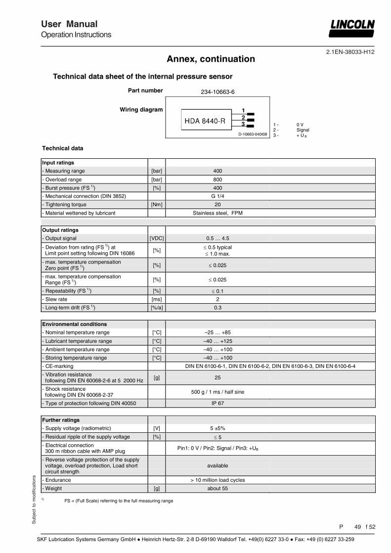
2.1EN-38033-H12
Sub
ject
to
mod
ifica
tions
User ManualOperation Instructions
P 49 f 52
Annex, continuation
Technical data sheet of the internal pressure sensor
Part number 234-10663-6
Wiring diagram
D-10663-040t08
1 - 0 V 2 - Signal 3 - + U B
Technical data
Input ratings
- Measuring range [bar] 400
- Overload range [bar] 800
- Burst pressure (FS 1)) [%] 400
- Mechanical connection (DIN 3852) G 1/4
- Tightening torque [Nm] 20
- Material wettened by lubricant Stainless steel, FPM
Output ratings
- Output signal [VDC] 0.5 … 4.5
- Deviation from rating (FS 1)) at Limit point setting following DIN 16086 [%] 0.5 typical
1.0 max.
- max. temperature compensation Zero point (FS 1)) [%] 0.025
- max. temperature compensation Range (FS 1)) [%] 0.025
- Repeatability (FS 1)) [%] 0.1
- Slew rate [ms] 2
- Long-term drift (FS 1)) [%/a] 0.3
Environmental conditions
- Nominal temperature range [°C] –25 … +85
- Lubricant temperature range [°C] –40 … +125
- Ambient temperature range [°C] –40 … +100
- Storing temperature range [°C] –40 … +100
- CE-marking DIN EN 6100-6-1, DIN EN 6100-6-2, DIN EN 6100-6-3, DIN EN 6100-6-4
- Vibration resistance following DIN EN 60068-2-6 at 5 2000 Hz [g] 25
- Shock resistance following DIN EN 60068-2-37 500 g / 1 ms / half sine
- Type of protection following DIN 40050 IP 67
Further ratings
- Supply voltage (radiometric) [V] 5 ±5%
- Residual ripple of the supply voltage [%] 5
- Electrical connection 300 m ribbon cable with AMP plug Pin1: 0 V / Pin2: Signal / Pin3: +UB
- Reverse voltage protection of the supply voltage, overload protection, Load short circuit strength
available
- Endurance > 10 million load cycles
- Weight [g] about 55
1) FS = (Full Scale) referring to the full measuring range
SKF Lubrication Systems Germany GmbH ● Heinrich Hertz-Str. 2-8 D-69190 Walldorf Tel. +49(0) 6227 33-0 ● Fax: +49 (0) 6227 33-259
2.1EN-38033-H12
Pag 50 f 52
User ManualOperation Instructions
Sub
ject
to
mod
ifica
tions
Notes:
SKF Lubrication Systems Germany GmbH ● Heinrich Hertz-Str. 2-8 D-69190 Walldorf Tel. +49(0) 6227 33-0 ● Fax: +49 (0) 6227 33-259
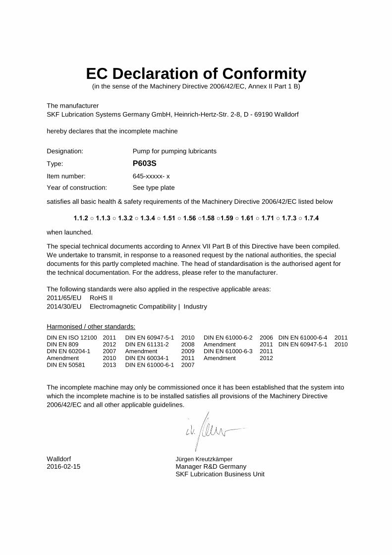
EC Declaration of Conformity (in the sense of the Machinery Directive 2006/42/EC, Annex II Part 1 B)
The manufacturer SKF Lubrication Systems Germany GmbH, Heinrich-Hertz-Str. 2-8, D - 69190 Walldorf
hereby declares that the incomplete machine
Designation: Pump for pumping lubricants
Type: P603S
Item number: 645-xxxxx- x
Year of construction: See type plate
satisfies all basic health & safety requirements of the Machinery Directive 2006/42/EC listed below
1.1.2 ○ 1.1.3 ○ 1.3.2 ○ 1.3.4 ○ 1.51 ○ 1.56 ○1.58 ○1.59 ○ 1.61 ○ 1.71 ○ 1.7.3 ○ 1.7.4
when launched.
The special technical documents according to Annex VII Part B of this Directive have been compiled. We undertake to transmit, in response to a reasoned request by the national authorities, the special documents for this partly completed machine. The head of standardisation is the authorised agent for the technical documentation. For the address, please refer to the manufacturer.
The following standards were also applied in the respective applicable areas: 2011/65/EU RoHS II 2014/30/EU Electromagnetic Compatibility | Industry
Harmonised / other standards: DIN EN ISO 12100 2011 DIN EN 60947-5-1 2010 DIN EN 61000-6-2 2006 DIN EN 61000-6-4 2011 DIN EN 809 2012 DIN EN 61131-2 2008 Amendment 2011 DIN EN 60947-5-1 2010 DIN EN 60204-1 2007 Amendment 2009 DIN EN 61000-6-3 2011 Amendment 2010 DIN EN 60034-1 2011 Amendment 2012 DIN EN 50581 2013 DIN EN 61000-6-1 2007 The incomplete machine may only be commissioned once it has been established that the system into which the incomplete machine is to be installed satisfies all provisions of the Machinery Directive 2006/42/EC and all other applicable guidelines. Walldorf Jürgen Kreutzkämper 2016-02-15 Manager R&D Germany SKF Lubrication Business Unit