Embed Size (px)
Citation preview
Single Lock Standing Seam Panel SystemInstallation Guide
� Product Description
� Universal Flashing Kit
� Supplemental Guide for VM Pro-Zinc Training
innovative solutionscladding design
To enroll in a VM PRO-ZINC Training Course contact:UMICORE BUILDING PRODUCTS USA, Inc.3120 Highwoods Blvd, Suite 104Raleigh, NC, 27604
Phone: 919 874 7173Fax: 919 874 7140www.vmzinc-us.com
Revision Date: 05.07.09 Please consult www.vmzinc-us.com for current revision and drawings
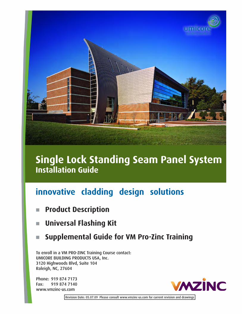
Panel Dims: 1" x 16 3/4" x LF Panels per crate: ~50 panels Max Length Dim: 42'- 0" Horiz, 15'-0" Vert
Vertical N/A Per LF 1.41 sq ft Horizontal 16 7/8" Per crate N/A
Radius: Convex Thickness: 0.8mm R1 10' field. Per LF 1.94 lb R2 36" pre-fab. Per crate N/A R2 30' fieldHORIZONTAL & VERTICAL
15' pre-fab.
On Center:
30' field
Concave
SINGLE LOCK STANDING SEAM
10' field.Weight:
Coverage:
Single Lock Standing Seam Panel SystemSpecification and Tolerances
Wall panel substrate and framing designs can vary greatly. The Architect should consult model building code, Umicore Building Products USA’s literature, or a building envelope consultant for additional information on appropriate wall designs. Consult Umicore Building Products USA, Inc. for assistance in editing the specific application.
Specifier Notes: Verify product compatibility if products other than those listed in this guide are to be specified and installed in conjunction with the metal wall panels.
QUALITY ASSURANCEVM ZINC® Single Lock Standing Seam is a factory-formed, zinc-alloy, metal wall panel system.
• Zinc Alloy: 99.995 percent electrolytic high-grade zinc with alloy additives of copper (0.08 percent to 0.20 percent), titanium (0.07 percent to 0.12 percent), and aluminum (0.015 percent).
• Thickness: .039” (1.00 mm).
Dimensional Tolerances:a. Coverage: Plus or minus 1/16” (1.6 mm).b. Flatness at Maximum Deflection: 5/64”
on 36” (2 mm on 914 mm).c. Curvature: 1/32” (0.8mm).
Installer’s Qualifications:• Engage an experienced installer who
has completed metal wall panel system installation similar in material, design, forming method, and extent to that indicated for this Project and with a record of successful in-service performance.
• Successful completion of VM PRO-ZINC Training course.
DELIVERY, STORAGE, AND HANDLINGDelivery:
• Inspect delivered materials on arrival. Report damaged materials to Umicore BP within 5 days.
• Deliver materials to site in Umicore BP’s original, unopened containers and packaging, with labels clearly identifying product name.
• Deliver materials so as not to be damaged or deformed.
• Package metal wall panels for protection during transportation and handling.
• Leave protective UV-resistant film on metal wall panels; Remove within 90 days after installation.
Storage and Handling:• Store materials in clean areas in
accordance with Umicore BP’s instructions.• Unload, store, and erect metal wall panels
in a manner to prevent bending, warping, twisting, and surface damage.
1
Flashing and Trim:• Field-fabricated from zinc-alloy sheets.• Thickness: [.031” (0.8 mm)]• Seal against weather.• Provide finished appearance.• Provide pull-out resistance and flatness.• Finish: Same zinc-alloy finish as adjacent
metal wall panel system.• Backside Coating Thickness: 60 microns.
Metal Wall Panels:• Form with Single Lock Standing Seam at
panel edges and smooth, flat pan.• Field install in sequential order.• Engage lower edge of each panel to upper
edge of panel below and engage right side of preceding panel’s left side.
• Mechanically attach panels to supports by locating concealed clips under upper and left edges of panels.
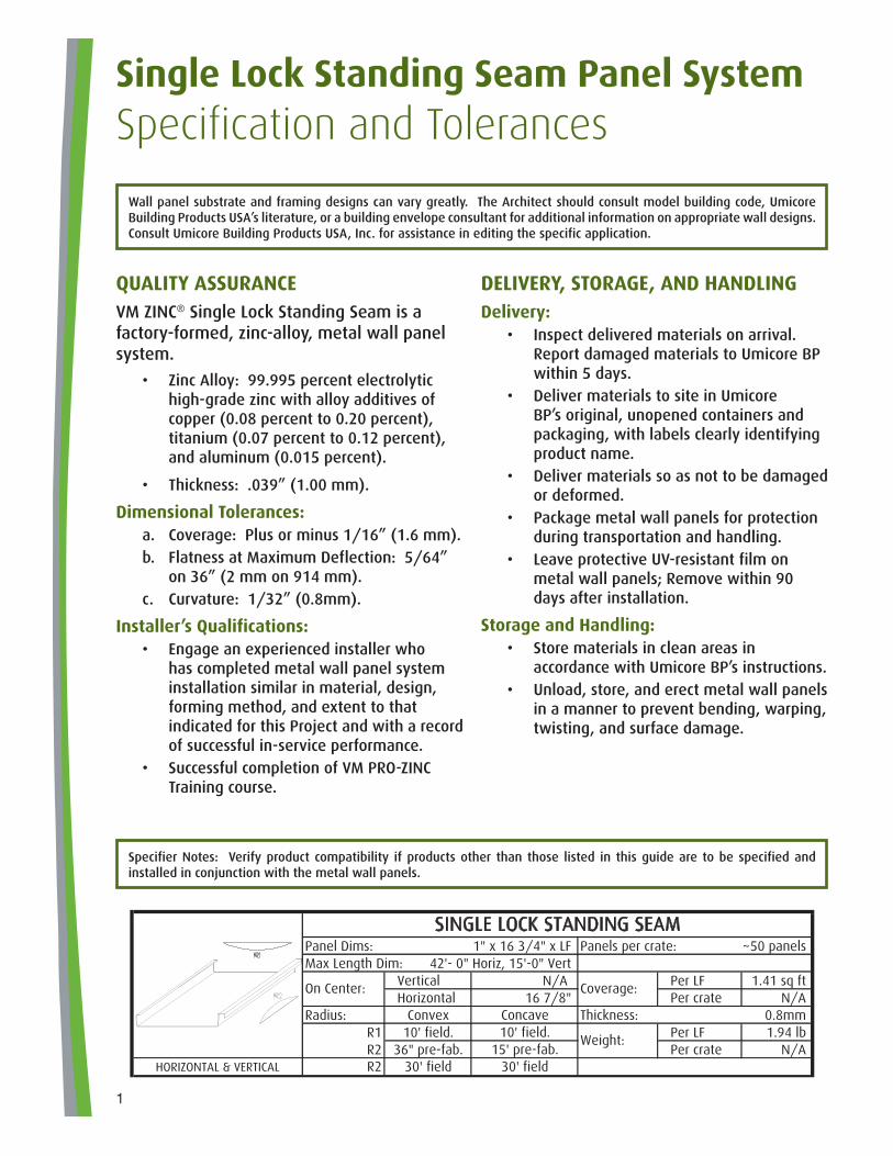
TABLE OF CONTENTSLayout ........................................ page 7
6 Points ..................................... page 8
Key Points .................................. page 9
Base of Wall ............................ page 11
Inside Corner ........................... page 12
Outside Corner ......................... page 13
Sill Flashing ............................. page 15
Jamb Flashing .......................... page 16
Head Flashing .......................... page 17
2
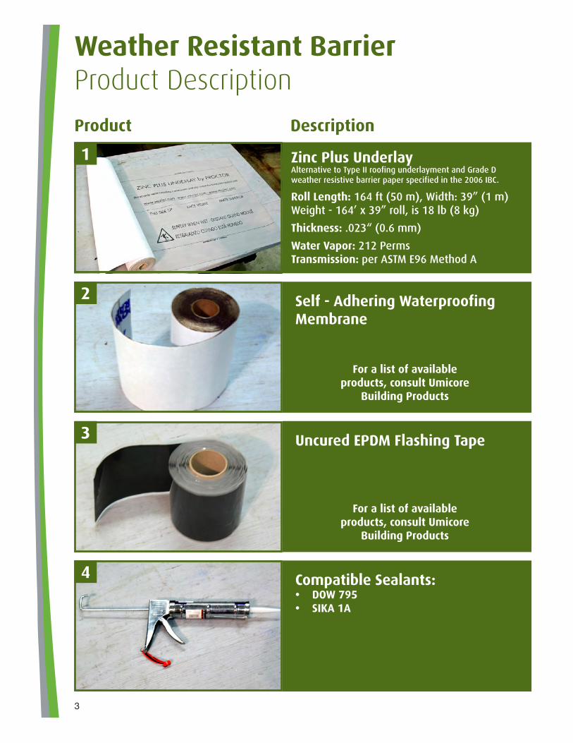
Weather Resistant BarrierProduct Description
Product Description
Self - Adhering Waterproofing Membrane
Uncured EPDM Flashing Tape
Compatible Sealants:• DOW 795• SIKA 1A
Zinc Plus Underlay Alternative to Type II roofing underlayment and Grade D weather resistive barrier paper specified in the 2006 IBC.
Roll Length: 164 ft (50 m), Width: 39” (1 m)Weight - 164’ x 39” roll, is 18 lb (8 kg)
Thickness: .023“ (0.6 mm)
Water Vapor: 212 PermsTransmission: per ASTM E96 Method A
For a list of available products, consult Umicore
Building Products
For a list of available products, consult Umicore
Building Products
1
2
3
4
3
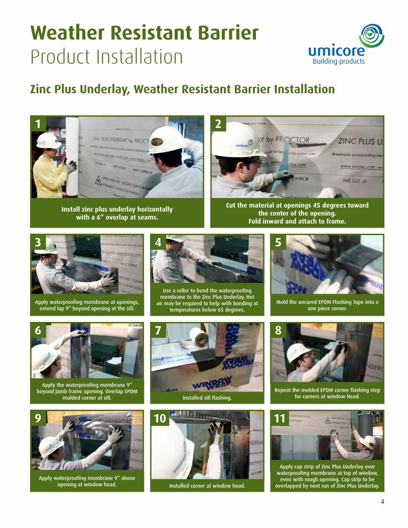
Weather Resistant BarrierProduct Installation
Zinc Plus Underlay, Weather Resistant Barrier Installation
Apply waterproofing membrane at openings, extend lap 9” beyond opening at the sill.
Mold the uncured EPDM Flashing Tape into a one piece corner.
Installed sill flashing.
Repeat the molded EPDM corner flashing step for corners at window Head.
Apply waterproofing membrane 9” above opening at window head. Installed corner at window head.
Apply cap strip of Zinc Plus Underlay over waterproofing membrane at top of window,
even with rough opening. Cap strip to be overlapped by next run of Zinc Plus Underlay.
Install zinc plus underlay horizontallywith a 6” overlap at seams.
Cut the material at openings 45 degrees towardthe center of the opening.
Fold inward and attach to frame.
1
3
6
9
4
7
10 11
5
8
2
Use a roller to bond the waterproofing membrane to the Zinc Plus Underlay. Hot
air may be required to help with bonding at temperatures below 65 degrees.
Apply the waterproofing membrane 9” beyond Jamb frame opening. Overlap EPDM
molded corner at sill.
4
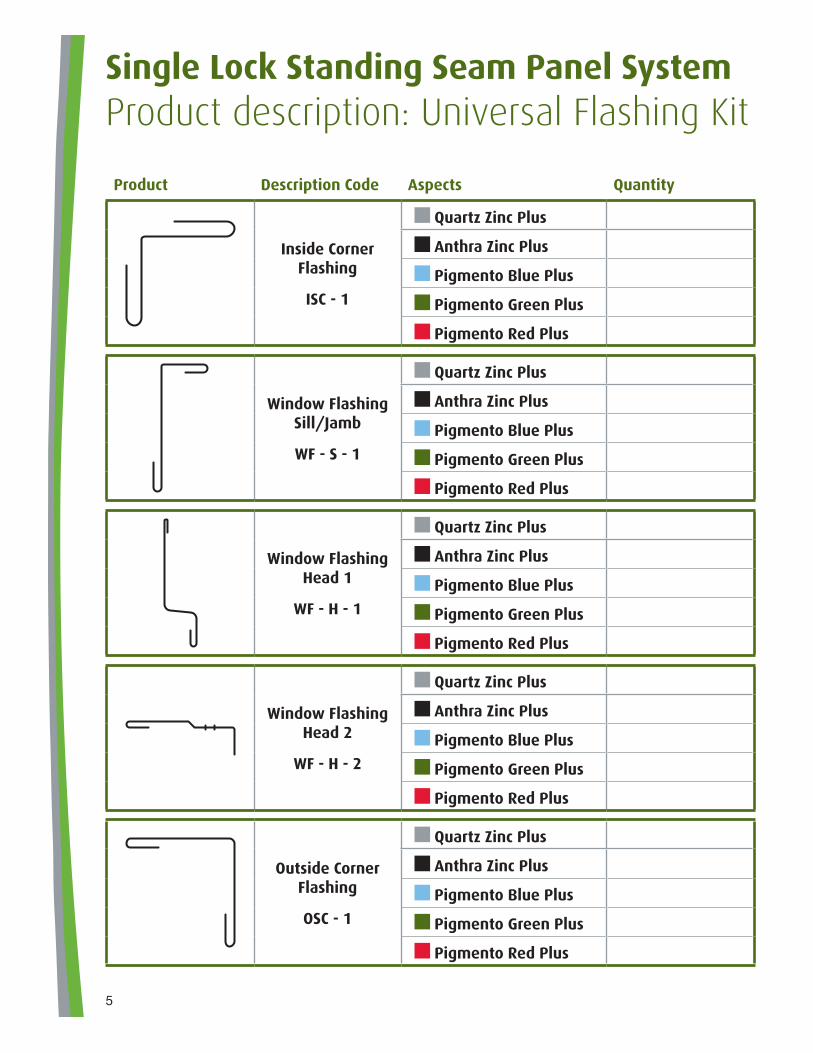
Product Description Code Aspects Quantity
Inside CornerFlashing
ISC - 1
Quartz Zinc Plus
Anthra Zinc Plus
Pigmento Blue Plus
Pigmento Green Plus
Pigmento Red Plus
Window FlashingSill/Jamb
WF - S - 1
Quartz Zinc Plus
Anthra Zinc Plus
Pigmento Blue Plus
Pigmento Green Plus
Pigmento Red Plus
Window FlashingHead 1
WF - H - 1
Quartz Zinc Plus
Anthra Zinc Plus
Pigmento Blue Plus
Pigmento Green Plus
Pigmento Red Plus
Window FlashingHead 2
WF - H - 2
Quartz Zinc Plus
Anthra Zinc Plus
Pigmento Blue Plus
Pigmento Green Plus
Pigmento Red Plus
Outside CornerFlashing
OSC - 1
Quartz Zinc Plus
Anthra Zinc Plus
Pigmento Blue Plus
Pigmento Green Plus
Pigmento Red Plus
Single Lock Standing Seam Panel SystemProduct description: Universal Flashing Kit
5
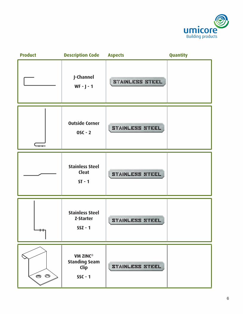
Product Description Code Aspects Quantity
J-Channel
WF - J - 1
Outside Corner
OSC - 2
Stainless SteelCleat
ST - 1
Stainless SteelZ-Starter
SSZ - 1
VM ZINC®
Standing Seam Clip
SSC - 1
6
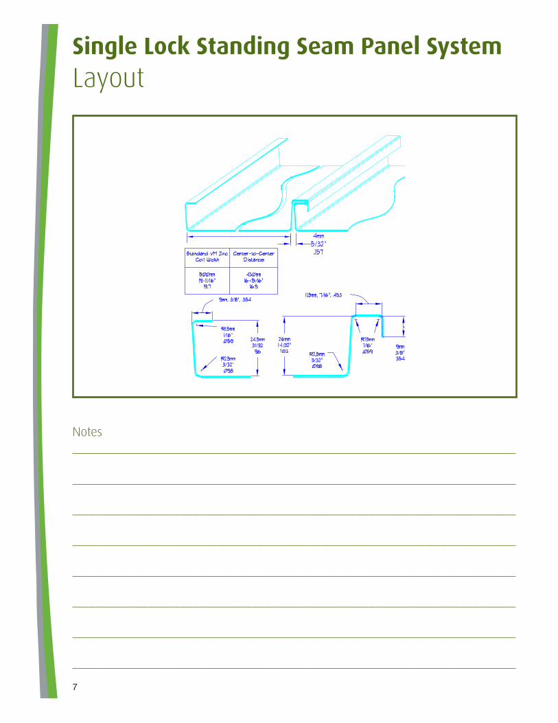
Single Lock Standing Seam Panel SystemLayout
Notes____________________________________________________________________
____________________________________________________________________
____________________________________________________________________
____________________________________________________________________
____________________________________________________________________
____________________________________________________________________
____________________________________________________________________
____________________________________________________________________
7
� Patina vs. Corrosion__________________________________________________________________________
__________________________________________________________________________
� Expansion and Contraction__________________________________________________________________________
__________________________________________________________________________
� Malleability__________________________________________________________________________
__________________________________________________________________________
� Interaction with other materials__________________________________________________________________________
__________________________________________________________________________
� Cold weather installation__________________________________________________________________________
__________________________________________________________________________
� Handling and Storage__________________________________________________________________________
__________________________________________________________________________
__________________________________________________________________________
__________________________________________________________________________
8
Single Lock Standing Seam Panel SystemNotes - Six Points
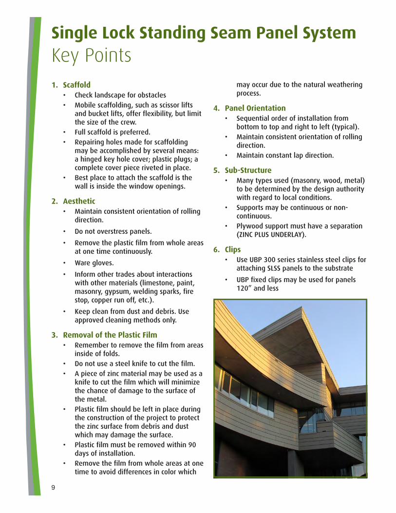
Single Lock Standing Seam Panel SystemKey Points1. Scaffold
• Check landscape for obstacles• Mobile scaffolding, such as scissor lifts
and bucket lifts, offer flexibility, but limit the size of the crew.
• Full scaffold is preferred.• Repairing holes made for scaffolding
may be accomplished by several means: a hinged key hole cover; plastic plugs; a complete cover piece riveted in place.
• Best place to attach the scaffold is the wall is inside the window openings.
2. Aesthetic• Maintain consistent orientation of rolling
direction.
• Do not overstress panels.
• Remove the plastic film from whole areas at one time continuously.
• Ware gloves.
• Inform other trades about interactions with other materials (limestone, paint, masonry, gypsum, welding sparks, fire stop, copper run off, etc.).
• Keep clean from dust and debris. Use approved cleaning methods only.
3. Removal of the Plastic Film• Remember to remove the film from areas
inside of folds.• Do not use a steel knife to cut the film.• A piece of zinc material may be used as a
knife to cut the film which will minimize the chance of damage to the surface of the metal.
• Plastic film should be left in place during the construction of the project to protect the zinc surface from debris and dust which may damage the surface.
• Plastic film must be removed within 90 days of installation.
• Remove the film from whole areas at one time to avoid differences in color which
may occur due to the natural weathering process.
4. Panel Orientation• Sequential order of installation from
bottom to top and right to left (typical).• Maintain consistent orientation of rolling
direction.• Maintain constant lap direction.
5. Sub-Structure• Many types used (masonry, wood, metal)
to be determined by the design authority with regard to local conditions.
• Supports may be continuous or non-continuous.
• Plywood support must have a separation (ZINC PLUS UNDERLAY).
6. Clips• Use UBP 300 series stainless steel clips for
attaching SLSS panels to the substrate
• UBP fixed clips may be used for panels 120” and less
9
• UBP sliding clips are required on long panels to allow for thermal expansion and contraction
• Consult UBP for proper location of fixed and sliding clips
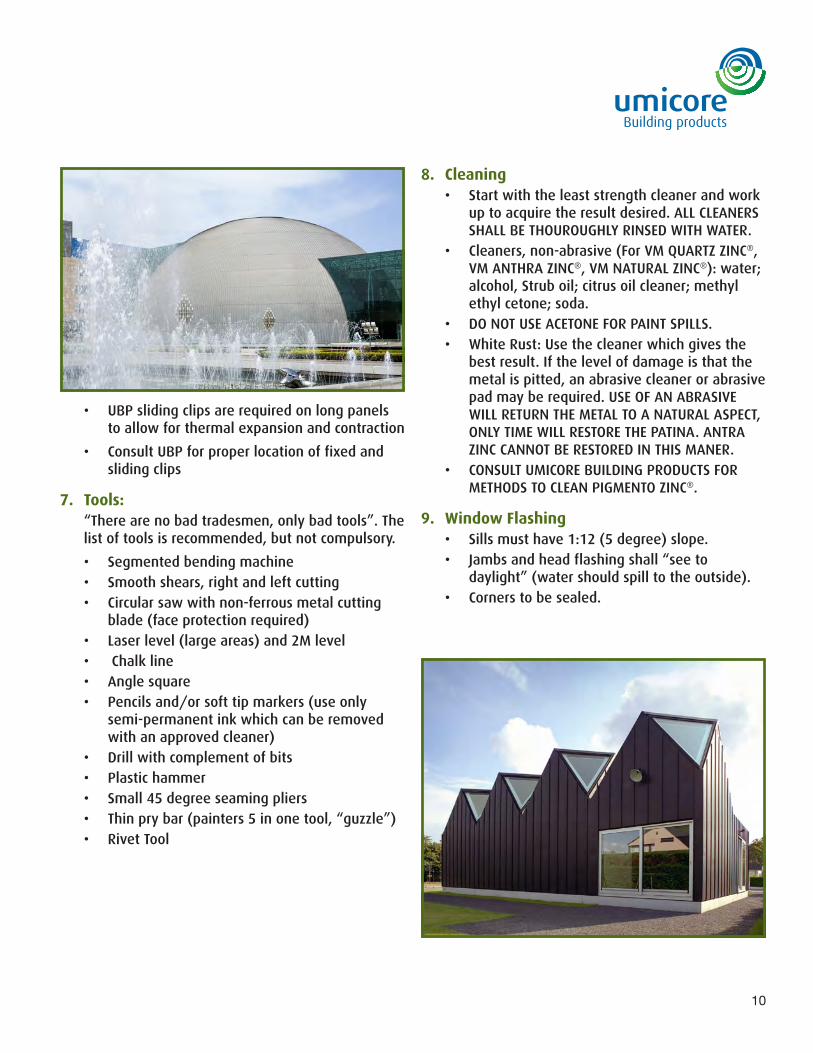
7. Tools: “There are no bad tradesmen, only bad tools”. The list of tools is recommended, but not compulsory.
• Segmented bending machine• Smooth shears, right and left cutting• Circular saw with non-ferrous metal cutting
blade (face protection required)• Laser level (large areas) and 2M level• Chalk line• Angle square• Pencils and/or soft tip markers (use only
semi-permanent ink which can be removed with an approved cleaner)
• Drill with complement of bits• Plastic hammer• Small 45 degree seaming pliers• Thin pry bar (painters 5 in one tool, “guzzle”)• Rivet Tool
8. Cleaning• Start with the least strength cleaner and work
up to acquire the result desired. ALL CLEANERS SHALL BE THOUROUGHLY RINSED WITH WATER.
• Cleaners, non-abrasive (For VM QUARTZ ZINC®, VM ANTHRA ZINC®, VM NATURAL ZINC®): water; alcohol, Strub oil; citrus oil cleaner; methyl ethyl cetone; soda.
• DO NOT USE ACETONE FOR PAINT SPILLS.• White Rust: Use the cleaner which gives the
best result. If the level of damage is that the metal is pitted, an abrasive cleaner or abrasive pad may be required. USE OF AN ABRASIVE WILL RETURN THE METAL TO A NATURAL ASPECT, ONLY TIME WILL RESTORE THE PATINA. ANTRA ZINC CANNOT BE RESTORED IN THIS MANER.
• CONSULT UMICORE BUILDING PRODUCTS FOR METHODS TO CLEAN PIGMENTO ZINC®.
9. Window Flashing• Sills must have 1:12 (5 degree) slope.• Jambs and head flashing shall “see to
daylight” (water should spill to the outside).• Corners to be sealed.
10
11
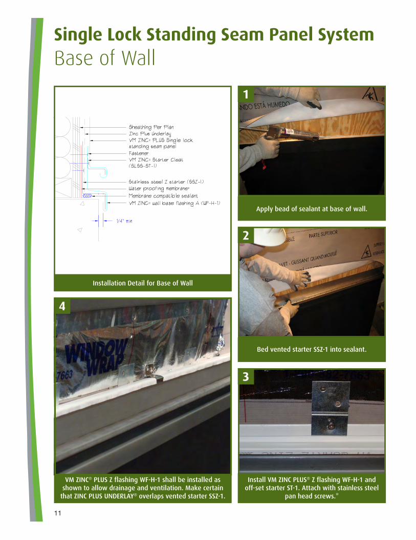
Apply bead of sealant at base of wall.
VM ZINC® PLUS Z flashing WF-H-1 shall be installed as shown to allow drainage and ventilation. Make certain
that ZINC PLUS UNDERLAY® overlaps vented starter SSZ-1.
Bed vented starter SSZ-1 into sealant.
Install VM ZINC PLUS® Z flashing WF-H-1 and off-set starter ST-1. Attach with stainless steel
pan head screws.*
Single Lock Standing Seam Panel SystemBase of Wall
Installation Detail for Base of Wall
1
4
3
2
12
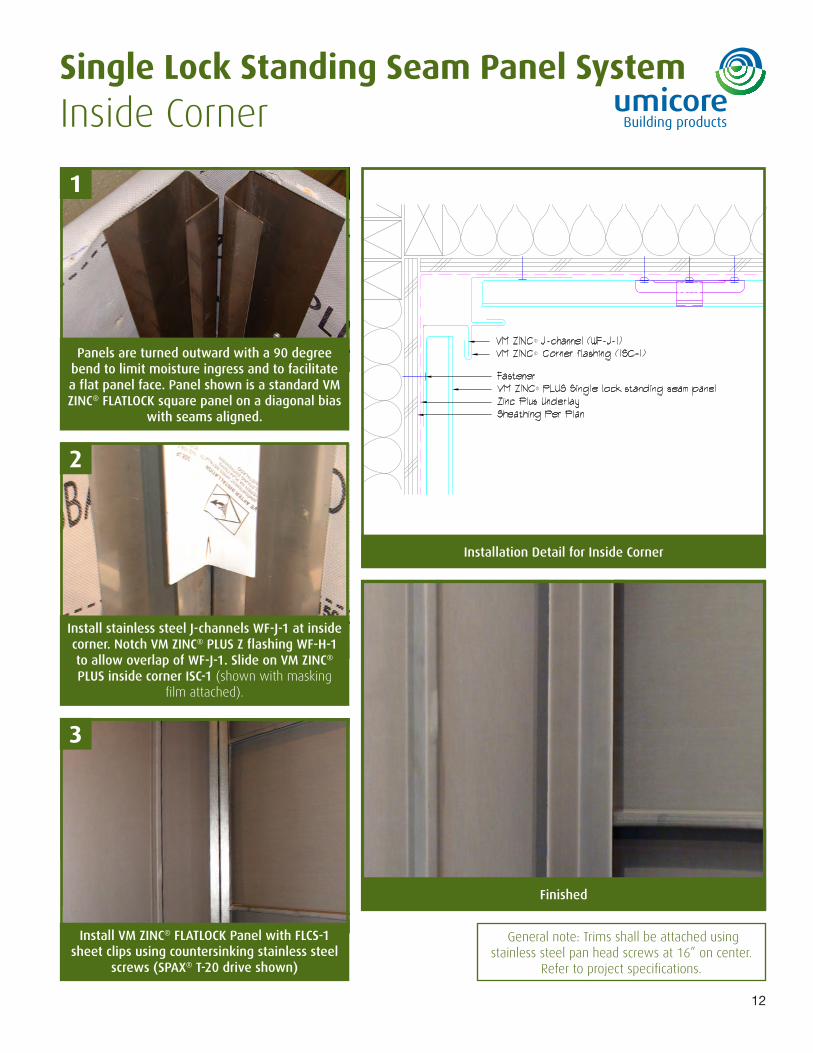
Panels are turned outward with a 90 degree bend to limit moisture ingress and to facilitate a flat panel face. Panel shown is a standard VM ZINC® FLATLOCK square panel on a diagonal bias
with seams aligned.
Install stainless steel J-channels WF-J-1 at inside corner. Notch VM ZINC® PLUS Z flashing WF-H-1 to allow overlap of WF-J-1. Slide on VM ZINC® PLUS inside corner ISC-1 (shown with masking
film attached).
Installation Detail for Inside Corner
Install VM ZINC® FLATLOCK Panel with FLCS-1 sheet clips using countersinking stainless steel
screws (SPAX® T-20 drive shown)
Single Lock Standing Seam Panel SystemInside Corner
1
3
2
Finished
General note: Trims shall be attached using stainless steel pan head screws at 16” on center.
Refer to project specifications.
13
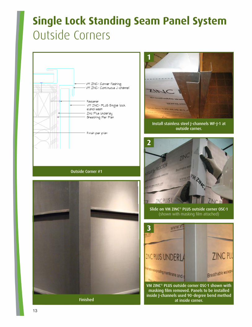
Install stainless steel J-channels WF-J-1 at outside corner.
Slide on VM ZINC® PLUS outside corner OSC-1 (shown with masking film attached)
VM ZINC® PLUS outside corner OSC-1 shown with masking film removed. Panels to be installed
inside J-channels used 90-degree bend method at inside corner.
Outside Corner #1
Single Lock Standing Seam Panel SystemOutside Corners
Finished
1
3
2
14
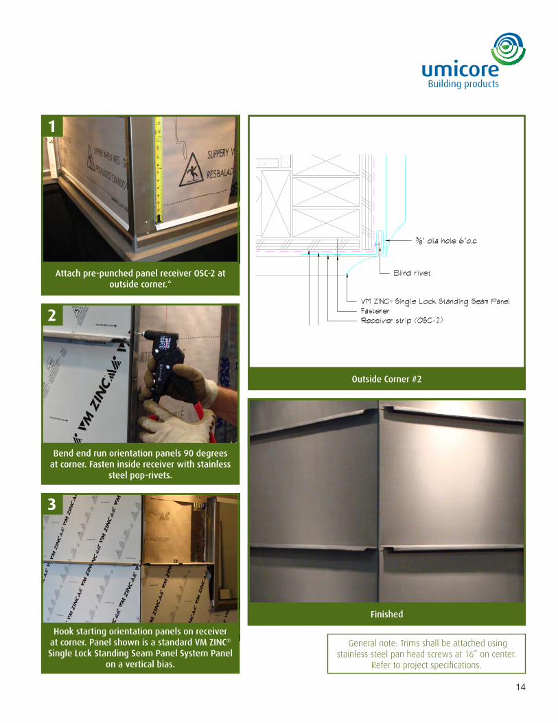
Attach pre-punched panel receiver OSC-2 at outside corner.*
Bend end run orientation panels 90 degrees at corner. Fasten inside receiver with stainless
steel pop-rivets.
Outside Corner #2
Hook starting orientation panels on receiver at corner. Panel shown is a standard VM ZINC® Single Lock Standing Seam Panel System Panel
on a vertical bias.
Finished
General note: Trims shall be attached using stainless steel pan head screws at 16” on center.
Refer to project specifications.
1
3
2
15
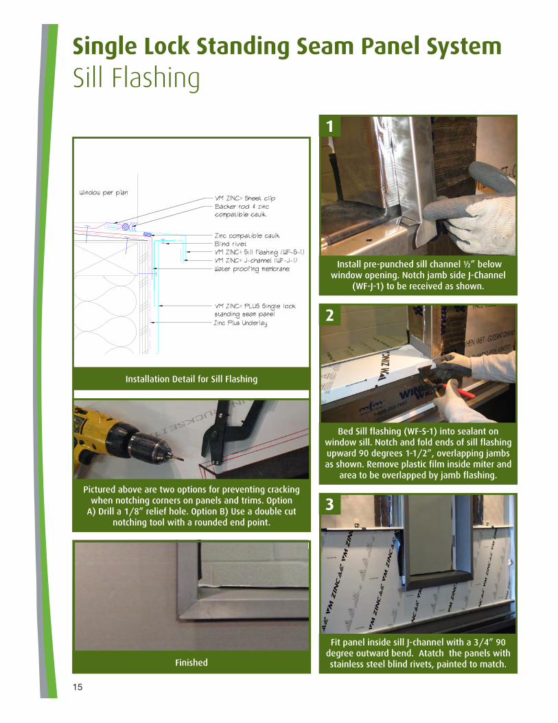
Install pre-punched sill channel ½” below window opening. Notch jamb side J-Channel
(WF-J-1) to be received as shown.
Bed Sill flashing (WF-S-1) into sealant on window sill. Notch and fold ends of sill flashing upward 90 degrees 1-1/2”, overlapping jambs as shown. Remove plastic film inside miter and
area to be overlapped by jamb flashing.
Fit panel inside sill J-channel with a 3/4” 90 degree outward bend. Atatch the panels with stainless steel blind rivets, painted to match.
Installation Detail for Sill Flashing
Finished
Single Lock Standing Seam Panel SystemSill Flashing
Pictured above are two options for preventing cracking when notching corners on panels and trims. Option
A) Drill a 1/8” relief hole. Option B) Use a double cut notching tool with a rounded end point.
1
3
2
16
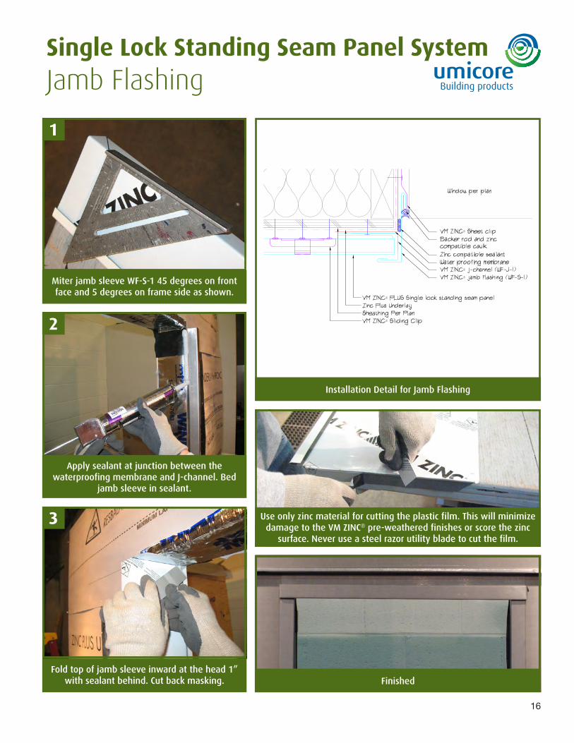
Miter jamb sleeve WF-S-1 45 degrees on front face and 5 degrees on frame side as shown.
Apply sealant at junction between the waterproofing membrane and J-channel. Bed
jamb sleeve in sealant.
Installation Detail for Jamb Flashing
FinishedFold top of jamb sleeve inward at the head 1”
with sealant behind. Cut back masking.
Single Lock Standing Seam Panel SystemJamb Flashing
Use only zinc material for cutting the plastic film. This will minimize damage to the VM ZINC® pre-weathered finishes or score the zinc
surface. Never use a steel razor utility blade to cut the film.
1
3
2
17
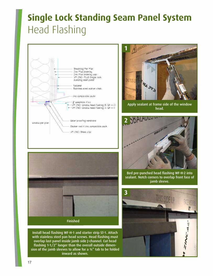
Apply sealant at frame side of the window head.
Bed pre-punched head flashing WF-H-2 into sealant. Notch corners to overlap front face of
jamb sleeve.
Single Lock Standing Seam Panel SystemHead Flashing
Install head flashing WF-H-1 and starter strip ST-1. Attach with stainless steel pan head screws. Head flashing must overlap last panel inside jamb side J-channel. Cut head flashing 1-1/2” longer than the overall outside dimen-
sion of the jamb sleeves to allow for a ¾” tab to be folded inward as shown.
Finished
1
3
2
18
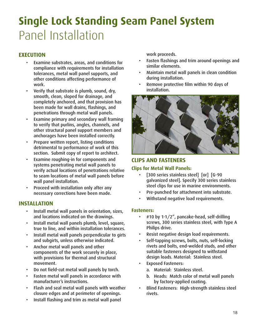
Single Lock Standing Seam Panel SystemPanel InstallationEXECUTION
• Examine substrates, areas, and conditions for compliance with requirements for installation tolerances, metal wall panel supports, and other conditions affecting performance of work.
• Verify that substrate is plumb, sound, dry, smooth, clean, sloped for drainage, and completely anchored, and that provision has been made for wall drains, flashings, and penetrations through metal wall panels.
• Examine primary and secondary wall framing to verify that purlins, angles, channels, and other structural panel support members and anchorages have been installed correctly.
• Prepare written report, listing conditions detrimental to performance of work of this section. Submit copy of report to architect.
• Examine roughing-in for components and systems penetrating metal wall panels to verify actual locations of penetrations relative to seam locations of metal wall panels before wall panel installation.
• Proceed with installation only after any necessary corrections have been made.
INSTALLATION• Install metal wall panels in orientation, sizes,
and locations indicated on the drawings.• Install metal wall panels plumb, level, square,
true to line, and within installation tolerances.• Install metal wall panels perpendicular to girts
and subgirts, unless otherwise indicated.• Anchor metal wall panels and other
components of the work securely in place, with provisions for thermal and structural movement.
• Do not field-cut metal wall panels by torch.• Fasten metal wall panels in accordance with
manufacturer’s instructions.• Flash and seal metal wall panels with weather
closure edges and at perimeter of openings.• Install flashing and trim as metal wall panel
work proceeds.• Fasten flashings and trim around openings and
similar elements.• Maintain metal wall panels in clean condition
during installation.• Remove protective film within 90 days of
installation.
CLIPS AND FASTENERSClips for Metal Wall Panels:
• [300 series stainless steel] [or] [G-90 galvanized steel]. Specify 300 series stainless steel clips for use in marine environments.
• Pre-punched for attachment into substrate.• Withstand negative load requirements.
Fasteners:• #10 by 1-1/2”, pancake-head, self-drilling
screws, 300 series stainless steel, with Type A Philips drive.
• Resist negative design load requirements.• Self-tapping screws, bolts, nuts, self-locking
rivets and bolts, end-welded studs, and other suitable fasteners designed to withstand design loads. Material: Stainless steel.
• Exposed Fasteners:a. Material: Stainless steel.b. Heads: Match color of metal wall panels
by factory-applied coating.• Blind Fasteners: High-strength stainless steel
rivets.
Single Lock Standing Seam Panel System
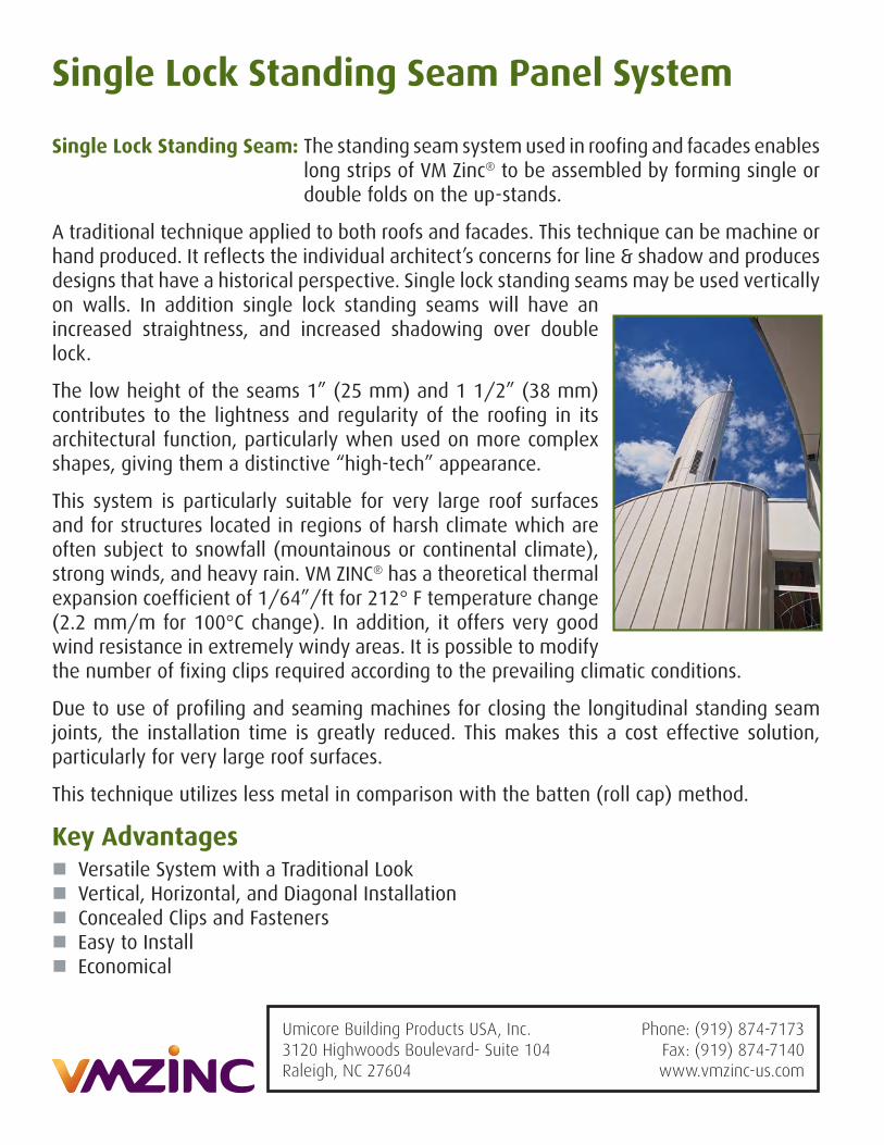
Single Lock Standing Seam: The standing seam system used in roofing and facades enables long strips of VM Zinc® to be assembled by forming single or double folds on the up-stands.
A traditional technique applied to both roofs and facades. This technique can be machine or hand produced. It reflects the individual architect’s concerns for line & shadow and produces designs that have a historical perspective. Single lock standing seams may be used vertically on walls. In addition single lock standing seams will have an increased straightness, and increased shadowing over double lock.
The low height of the seams 1” (25 mm) and 1 1/2” (38 mm) contributes to the lightness and regularity of the roofing in its architectural function, particularly when used on more complex shapes, giving them a distinctive “high-tech” appearance.
This system is particularly suitable for very large roof surfaces and for structures located in regions of harsh climate which are often subject to snowfall (mountainous or continental climate), strong winds, and heavy rain. VM ZINC® has a theoretical thermal expansion coefficient of 1/64”/ft for 212° F temperature change (2.2 mm/m for 100°C change). In addition, it offers very good wind resistance in extremely windy areas. It is possible to modify the number of fixing clips required according to the prevailing climatic conditions.
Due to use of profiling and seaming machines for closing the longitudinal standing seam joints, the installation time is greatly reduced. This makes this a cost effective solution, particularly for very large roof surfaces.
This technique utilizes less metal in comparison with the batten (roll cap) method.
Key Advantages � Versatile System with a Traditional Look � Vertical, Horizontal, and Diagonal Installation � Concealed Clips and Fasteners � Easy to Install � Economical
Umicore Building Products USA, Inc.3120 Highwoods Boulevard- Suite 104Raleigh, NC 27604
Phone: (919) 874-7173Fax: (919) 874-7140www.vmzinc-us.com