Embed Size (px)
Citation preview

Single Mode
Fibres for DARWIN
Doc. No: SMF-AB-Astrium-01 Issue: 1 Date: 30 July 2004 File: SMF-Abstract-01.doc Pages: 17
Title:
Single Mode Fibres for DARWIN ABSTRACT
Contract No.: ESTEC/Contract No. AO/1-4023/01/NL/CK
Single Mode Fibres for DARWIN
Prepared by: R. Flatscher / Astrium AED411 Date: 30 July 2004
Checked by: O. Wallner
V. Artjushenko
Date:
30 July 2004
30 July 2004
Project Management: R. Flatscher
Distribution: see Distribution List
Copying of this document, and giving it to others and the use or communication of the contents there-of, are forbidden without express
authority. Offenders are liable to the payment of damages. All rights are reserved in the event of the grant of a patent or the registration of a
utility model or design.

Distribution List
Single Mode Fibres for DARWIN
Doc. No: SMF-AB-Astrium-01 Issue: 1 Date: 30 July 2004 File: SMF-Abstract-01.doc Page A-I
Quantity Name Dep./Comp. Quantity Name Dep./Comp.
20 J.P.N. Pereira Do Carmo ESTEC
1 W. Leeb TU-Wien
1 V. Artiouchenko ART-Photonics
1 R. Flatscher EADS Astrium
1 O. Wallner TU-Wien

Change Record
Single Mode Fibres for DARWIN
Doc. No: SMF-AB-Astrium-01 Issue: 1 Date: 30 July 2004 File: SMF-Abstract-01.doc Page B-I
Issue Date Sheets Description of Change Release
1
30 July 2004
all
initial issue
1

Register of Changes
Single Mode Fibres for DARWIN
Doc. No: SMF-AB-Astrium-01 Issue: 1 Date: 30 July 2004 File: SMF-Abstract-01.doc Page C-I
Issue 1 2 3 4 5 6 7 8 Issue 1 2 3 4 5 6 7 8
Dat
e
Dat
e
Sheet Sheet

Single Mode Fibres for DARWIN
Doc. No: SMF-AB-Astrium-01 Issue: 1 Date: 30 July 2004 File: SMF-Abstract-01.doc Page i
Table of Contents
1 BACKGROUND 1
2 PROJECT TEAM AND RESPONSIBILITIES 1
3 TECHNICAL REQUIREMENTS 2
4 MANUFACTURED SINGLE MODE FIBRES 4
4.1 Design Limitations 4
4.2 Step-index Fibres Made of Silver Halides 4
4.3 Photonic Crystal Fibres Made of Silver Halides 6
4.4 Chalcogenide Fibres Made of Arsenic Sulfide 7
4.5 Chalcogenide Fibres Made of GAST 7
5 PHOTOGRAPHS OF MANUFACTURED FIBRES 7
6 TEST SET-UP AND MEASUREMENTS 9
7 CRITICAL PARAMETERS AND PROCESSES 11
7.1 Step-index Fibres Made of Silver Halides 11
7.2 Photonic Crystal Fibres Made of Silver Halides 12
7.3 Chalcogenide Fibres Made of Arsenic Sulfide 13
7.4 Chalcogenide Fibres Made of GAST 13
7.5 Limitations of Mode Suppression Measurement 13
8 CONCLUSIONS 14
9 RECOMMENDATIONS AND CONTINUATION 15
9.1 Splitting Into Sub-bands 15
9.2 Improvements on Silver Halides 16

Single Mode Fibres for DARWIN
Doc. No: SMF-AB-Astrium-01 Issue: 1 Date: 30 July 2004 File: SMF-Abstract-01.doc Page ii
9.3 Improvement of Measurement Equipment 16
9.4 Continuation 17

Single Mode Fibres for DARWIN
Doc. No: SMF-AB-Astrium-01 Issue: 1 Date: 30 July 2004 File: SMF-Abstract-01.doc Page 1
1 BACKGROUND
This technology development activity was concerned with the development of single-mode fibres to be used as a wavefront filters within ESA’s DARWIN mission.
The DARWIN planet finding mission, with capability for imaging and spectroscopy science, operating in the thermal infrared spectral region requires that wavefront errors have to be reduced to a very high degree in order to achieve the required nulling quality. The required high wavefront quality can only be achieved with adequate wavefront filtering and single mode fibres in general have excellent mode filtering capabilities, but they were not yet available for the specific wavelength region of Darwin.
The single mode optical fibre makes use of the fact that in the operational spectral bandwidth of the fibre only the fundamental mode (of nearly Gaussian mode profile) propagates, whereas any higher order modes are strongly attenuated. The wavelength limit for single mode operation is mainly determined by the core diameter and the difference in the refractive index of core and cladding. A commonly used parameter describing this physical relation is the normalized frequency V given by
2 22 2 2.405core cladV NA n nρ π ρ πλ λ
= = − < ,
with ρ denoting the fibre core radius, λ is the wavelength, and n is the refractive index of core respectively cladding. For a step-index profile fibre, single mode operation is given for V<2.4. The fibre will convert, to some extent, axial offset and tilt of the input beam into increased insertion loss, which can be compensated more easily.
A major challenge associated with this activity is to find a material that can be used for the wavefront filtering device. This difficulty arises from the fact that silica is no longer transparent for wavelengths beyond 4 microns. Materials transparent in the range from 4 to 20 µm are Gallium-Lanthanum Sulfide (GLS) glass and poly-crystalline silver-halide (AgCl). The latter has been investigated in detail and several fibre samples have been produced. Good candidate materials for the wavelength range up to about 10 µm are chalcogenide glasses, comprising such elements as Se, S or Te, associated with Ge, Si, As or Sb.
2 PROJECT TEAM AND RESPONSIBILITIES
EADS Astrium Germany has been awarded this manufacturing activity of a single-mode fibre suitable for modal wavefront filtering within the Darwin. The project team is composed of ART-Photonics (Germany), TU Wien1 (Austria), and IRCOM2 (France). ART-Photonics is the world-market leader on multi-mode fibres made of silver-halides and claims several patents on the production of high purity fibres. In addition TU Wien is involved in the DARWIN multi-aperture imaging interferometer breadboard and in the GENIE study.
1 Institute of Communications and Radio-Frequency Engineering, Vienna University of Technology 2 Institute de Recherche en Communications Optiques et Microondes, Université de Limoges

Single Mode Fibres for DARWIN
Doc. No: SMF-AB-Astrium-01 Issue: 1 Date: 30 July 2004 File: SMF-Abstract-01.doc Page 2
The responsibilities of the team members are as follows:
EADS Astrium Germany as prime contractor responsible for system engineering, trade-off and selection of technology, test plan, analysis of results and recommendations for continuations
ART-Photonics review of infrared materials, responsible for detailed design of the waveguide and the manufacturing of preforms and fibres, establishing of all required tools and auxiliary equipment for extruding and drawing the fibres, quality control
TU Wien theoretical analysis of waveguiding principles, established a test interferometer using as source a CO2-laser, performed optical, cryogenic, and hard radiation tests
IRCOM numerical simulations of beam propagation within the fibres
Besides the basic funding provided by ESA, substantial internal funding has been added by ART-Photonics to develop numerous tools and manufacturing processes for producing three different types of silver-halide step-index fibres, four different types of index-guiding photonic-crystal fibres, and two different types of chalcogenide glass fibres.
3 TECHNICAL REQUIREMENTS
The objective of this manufacturing activity is to develop single-mode fibres to be used as spatial wavefront filter within the DARWIN infrared spectral range from 4 to 20 µm. This activity focuses on the design of the waveguide structure and on search and selection of proper materials. It comprises theoretical analysis, design, manufacturing, and testing of samples of single-mode fibres.
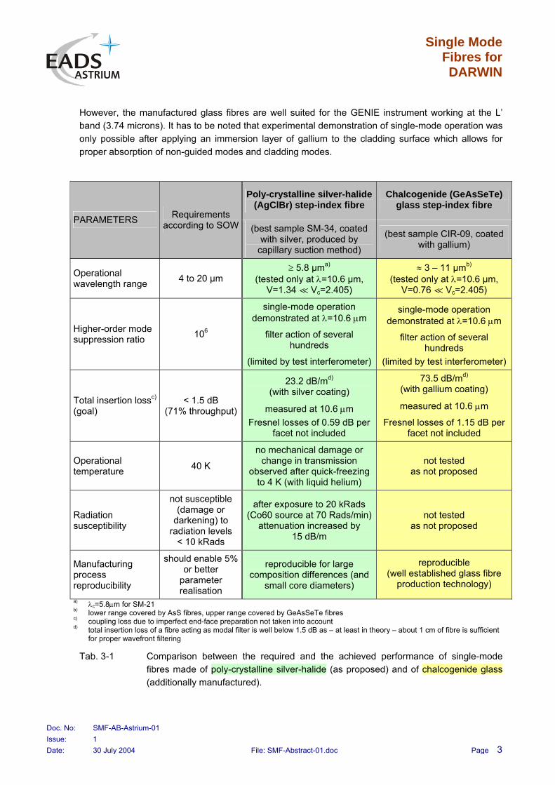
In Tab. 3-1 the requirements on the single-mode fibres as given in the SOW are compared with the results actually obtained within the project. The results for both, the initially proposed poly-crystalline silver-halide fibres produced by plastic extrusion and drawn chalcogenide glass fibres are compared. The latter technology was introduced (and the related work performed within the frame of CCN2 replaced the work originally planned for WP 6000) because single-mode fibre fabrication by extrusion seemed to fail for a long time. Successful coating of silver-halide fibres with silver and the resulting experimental confirmation of single-mode operation was managed not until the very end of the project.
Several of the silver-halide fibre samples produced were expected to be single-mode from the measured fibre parameters like core diameter and core and cladding refractive indices. Though, no spatially steady output field distribution and thus no single-mode operation could be obtained. The reasons were micro-cracks at the core/cladding boundary caused by the multi-stage extrusion process, core and cladding material inhomogeneities, and reflections at the cladding/air interface. Applying an immersion layer of silver allowed for proper absorption of non-guided modes and cladding modes, thus enabling a single spatial mode at the fibre output.
Chalcogenide glass seemed to be an alternative to poly-crystalline silver-halide. Because of its properties it is much easier to produce single-mode fibres of sufficient quality. The drawback is that chalcogenide glass covers only a part of the wavelength range required for the DARWIN mission.
Single Mode Fibres for DARWIN
Doc. No: SMF-AB-Astrium-01 Issue: 1 Date: 30 July 2004 File: SMF-Abstract-01.doc Page 3
However, the manufactured glass fibres are well suited for the GENIE instrument working at the L’ band (3.74 microns). It has to be noted that experimental demonstration of single-mode operation was only possible after applying an immersion layer of gallium to the cladding surface which allows for proper absorption of non-guided modes and cladding modes.
Poly-crystalline silver-halide (AgClBr) step-index fibre
Chalcogenide (GeAsSeTe) glass step-index fibre
PARAMETERS Requirements according to SOW (best sample SM-34, coated
with silver, produced by capillary suction method)
(best sample CIR-09, coated with gallium)
Operational wavelength range 4 to 20 µm
≥ 5.8 µma) (tested only at λ=10.6 µm,
V=1.34 á Vc=2.405)
≈ 3 – 11 µmb) (tested only at λ=10.6 µm,
V=0.76 á Vc=2.405)
Higher-order mode suppression ratio 106
single-mode operation demonstrated at λ=10.6 µm
filter action of several hundreds
(limited by test interferometer)
single-mode operation demonstrated at λ=10.6 µm
filter action of several hundreds
(limited by test interferometer)
Total insertion lossc) (goal)
< 1.5 dB (71% throughput)
23.2 dB/md)
(with silver coating)
measured at 10.6 µm Fresnel losses of 0.59 dB per
facet not included
73.5 dB/md)
(with gallium coating)
measured at 10.6 µm
Fresnel losses of 1.15 dB per facet not included
Operational temperature 40 K
no mechanical damage or change in transmission
observed after quick-freezing to 4 K (with liquid helium)
not tested as not proposed
Radiation susceptibility
not susceptible (damage or
darkening) to radiation levels
< 10 kRads
after exposure to 20 kRads (Co60 source at 70 Rads/min)
attenuation increased by 15 dB/m
not tested as not proposed
Manufacturing process reproducibility
should enable 5% or better
parameter realisation
reproducible for large composition differences (and
small core diameters)
reproducible (well established glass fibre
production technology)
a)
b)
c)
d)
λc=5.8µm for SM-21 lower range covered by AsS fibres, upper range covered by GeAsSeTe fibres coupling loss due to imperfect end-face preparation not taken into account total insertion loss of a fibre acting as modal filter is well below 1.5 dB as – at least in theory – about 1 cm of fibre is sufficient for proper wavefront filtering
Tab. 3-1 Comparison between the required and the achieved performance of single-mode fibres made of poly-crystalline silver-halide (as proposed) and of chalcogenide glass (additionally manufactured).

Single Mode Fibres for DARWIN
Doc. No: SMF-AB-Astrium-01 Issue: 1 Date: 30 July 2004 File: SMF-Abstract-01.doc Page 4
4 MANUFACTURED SINGLE MODE FIBRES
4.1 Design Limitations
The core radius ρ and numerical aperture NA of a step-index single-mode fibre can be traded for a given wavelength because the requirement for single-mode operation reads as ρ⋅NA ≤ 0.38⋅λmin. The fibres have to be designed to be single-mode at the shortest wavelength in question (λmin).
During the project it turned out that a lower limit is given for the composition difference between core and cladding of a silver-halide fibre. The lower limit is as high as about 2% and it is obtained for the eutectic composition with 25% AgCl and 75% AgBr. It is a result of the physical structure of the silver-halide crystal. A further reduction of the composition difference would yield merging of the core/cladding boundaries and no step index could be observed any longer. On the other hand it would be easier to produce fibres with large cores as the number of extrusions could be reduced in the preform manufacturing stage. The numerous extrusions are seen as the most important reason for the formation of scattering centres, disruptions, and cracks in the boundary of core and cladding.
Further it turned out that an absorbing coating is mandatory to obtain single-mode operation within a reasonable length. Such an absorbing coating is of particular importance for mid-infrared fibres as the high refractive indices cause strong back-reflections from the cladding/air interface.
4.2 Step-index Fibres Made of Silver Halides
To manufacture step-index fibres made of poly-crystalline material, first preforms are produced. The preforms are extruded in multiple steps to reduce the core diameter. With a final extrusion step the single-mode fibre with the required small core diameter is realized. During this project, the preforms were produced by three different methods
1) mechanical combining of core and cladding preform,
2) capillary drop and capillary suction method, and
3) preform growth from the melt.
The dropping technique is supported by capillary forces if the core diameter is reduced. The minimum core diameter achieved in the preform stage was around 0.6 to 1 mm. The refined dropping method converted into a capillary suction method where the melted core material was fed in by a reservoir at the bottom of the ampoule.
High material quality can be achieved only by avoiding any contamination in the fibre manufacturing process. Contaminations are mainly brought in by
mechanical toolings forming the core rod and the cladding tube,
handling the preforms in ambient environment (moisture, etc.), and
residuals from the final cleaning processes.
The contamination during the preform manufacturing can be reduced step-wise by applying the improved methods proposed above. Mechanical combining of core and cladding is the most

Single Mode Fibres for DARWIN
Doc. No: SMF-AB-Astrium-01 Issue: 1 Date: 30 July 2004 File: SMF-Abstract-01.doc Page 5
contaminated process whereas the growth from the melt process avoids any tools and no environmental atmosphere is disturbing the growing process.
Fig. 4-1 shows, as an example, the principle of the capillary drop preform manufacturing technique. The fibre is manufactured by plastic extrusion from the preform.
Fig. 4-1 Principle of dropping method for preform manufacturing. Reducing the core diameter yields the capillary drop method. Providing the melted core material from a bottom reservoir gives the capillary suction method.
More than 30 fibre samples have been manufactured from all three methods. Method 1, based on mechanical deformation, was found to produce many scattering defects. Nevertheless, some of the experimental samples have been made according to the required design with small core diameter and low refractive index difference between core and cladding. However, the produced single-mode fibres were only of poor quality. The samples produced by method 2, based on capillary suction, had by far the best quality. Several samples had right geometry and numerical aperture. Nevertheless, initially single-mode operation could not be demonstrated experimentally. Roughening the cladding surface and/or applying black point did not result in any improvement. Only applying an immersion layer of silver allowed for proper absorption of non-guided modes and cladding modes, thus enabling a single spatial mode at the fibre output.
Single Mode Fibres for DARWIN
Doc. No: SMF-AB-Astrium-01 Issue: 1 Date: 30 July 2004 File: SMF-Abstract-01.doc Page 6
The method of preform growth from the melt was too complex and the process controlling was too difficult to produce fibre samples with correct geometry and correct composition. Nevertheless, samples have been manufactured by this method but have not been tested with the interferometer.
4.3 Photonic Crystal Fibres Made of Silver Halides
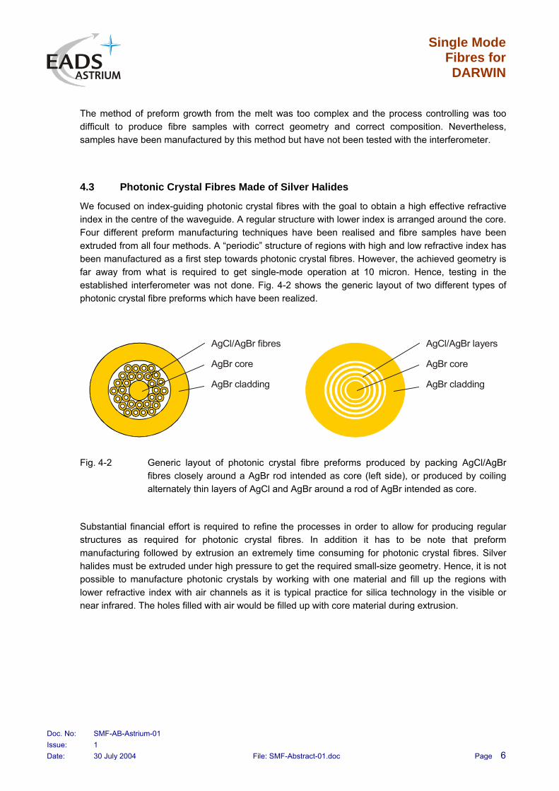
We focused on index-guiding photonic crystal fibres with the goal to obtain a high effective refractive index in the centre of the waveguide. A regular structure with lower index is arranged around the core. Four different preform manufacturing techniques have been realised and fibre samples have been extruded from all four methods. A “periodic” structure of regions with high and low refractive index has been manufactured as a first step towards photonic crystal fibres. However, the achieved geometry is far away from what is required to get single-mode operation at 10 micron. Hence, testing in the established interferometer was not done. Fig. 4-2 shows the generic layout of two different types of photonic crystal fibre preforms which have been realized.
AgBr core
AgCl/AgBr fibres
AgBr cladding
AgBr core
AgCl/AgBr layers
AgBr cladding
Fig. 4-2 Generic layout of photonic crystal fibre preforms produced by packing AgCl/AgBr fibres closely around a AgBr rod intended as core (left side), or produced by coiling alternately thin layers of AgCl and AgBr around a rod of AgBr intended as core.
Substantial financial effort is required to refine the processes in order to allow for producing regular structures as required for photonic crystal fibres. In addition it has to be note that preform manufacturing followed by extrusion an extremely time consuming for photonic crystal fibres. Silver halides must be extruded under high pressure to get the required small-size geometry. Hence, it is not possible to manufacture photonic crystals by working with one material and fill up the regions with lower refractive index with air channels as it is typical practice for silica technology in the visible or near infrared. The holes filled with air would be filled up with core material during extrusion.

Single Mode Fibres for DARWIN
Doc. No: SMF-AB-Astrium-01 Issue: 1 Date: 30 July 2004 File: SMF-Abstract-01.doc Page 7
4.4 Chalcogenide Fibres Made of Arsenic Sulfide
Several glassy fibres have been manufactured to demonstrate single-mode behaviour at least in a restricted wavelength range up to about 10 µm. Chalcogenide glasses made of arsenic sulphide (AsS) are already well established in the near infrared. The big advantage of glassy fibres is that they can be drawn, thus yielding small core diameters and perfectly shaped cores. A fibre sample with diameters of 6 and 125 µm for core and cladding has been manufactured. It is expected to be single-mode for wavelength up from 3 microns. The (bulk) material is transparent up to 6 µm.
The sample was not tested because our measurement set-up is equipped with a CO2-laser emitting at 10.6 µm. Changing the laser source would imply the exchange of all optical elements of the interferometer now optimised for 10 µm.
4.5 Chalcogenide Fibres Made of GAST
GeAsSeTe glass is composed of germanium, arsenic, selenium, and tellurium. Germanium is used to reduce some absorption features produced by water within the fibre. The material is transparent up to about 12 µm. Several samples have been manufactured and characterised with the 10 µm test interferometer. Measurements with and without primary coating have been conducted. The fibres with core diameters of 17, 23, and 25 micron yielded single-mode operation if a metallic gallium coating was attached onto the cladding surface. Only applying an immersion layer of silver allowed for proper absorption of non-guided modes and cladding modes, thus enabling a single spatial mode at the fibre output.
GeAsSeTe fibres are the most promising candidates for the GENIE instrument operating at the L’ band.
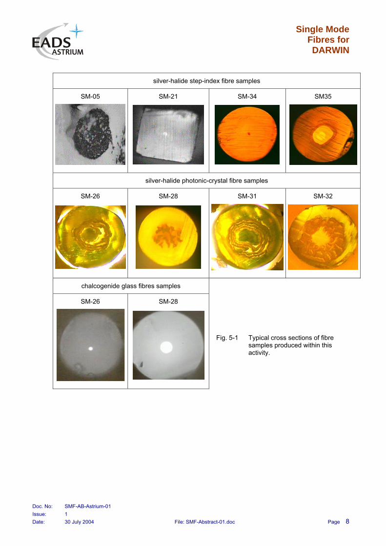
5 PHOTOGRAPHS OF MANUFACTURED FIBRES
The following Fig. 5-1 shows typical cross-sections of fibre samples manufactured within this activity. After applying a proper absorption coating, single-mode operation at a wavelength of 10.6 µm has been demonstrated for silver-halide fibres as well as for chalcogenide glass fibres. Chalcogenide glass fibres can be used within the first octave of the DARWIN wavelength range. Arsenic-sulfide fibres are transparent up to about 6 µm, GeAsSeTe fibres are transparent up to about 12 µm. Silver-halide fibres can be used within the entire DARWIN wavelength range. However, the fibre samples manufactured during this project are single-mode only for wavelengths lager than about 8 µm.
Single Mode Fibres for DARWIN
Doc. No: SMF-AB-Astrium-01 Issue: 1 Date: 30 July 2004 File: SMF-Abstract-01.doc Page 8
silver-halide step-index fibre samples
SM-05 SM-21 SM-34 SM35
silver-halide photonic-crystal fibre samples
SM-26 SM-28 SM-31 SM-32
chalcogenide glass fibres samples
SM-26 SM-28
Fig. 5-1 Typical cross sections of fibre samples produced within this activity.

Single Mode Fibres for DARWIN
Doc. No: SMF-AB-Astrium-01 Issue: 1 Date: 30 July 2004 File: SMF-Abstract-01.doc Page 9
6 TEST SET-UP AND MEASUREMENTS
Higher-order mode suppression, as asked for in the SOW, cannot be measured as a matter of principle. However, what is important for a fibre acting as a modal wavefront filter is the uniqueness of the fibre output field, independent of the fibre input field. This property can be achieved with a single-mode fibre and can be measured with an interferometer.
We set up a test interferometer with a CO2 laser operating at a wavelength of 10.6 µm. Because of the spatial filtering capability of single-mode fibres, the rejection ratio R2 (ratio of constructive to destructive interference) at the output of a Mach-Zehnder interferometer is supposed to be much higher when employing a modal filter at the output compared to the rejection ratio R1 achievable with the interferometer itself. This improvement in rejection ratio can be designated the fibre’s filter action M=R2/R1. A block diagram of the measurement setup is shown in Fig. 6-1 together with the measurement principle.
beamsplitter 2
beamsplitter 3
mirror 2
monitoring
detector 1
oscilloscope
controlelectronics
detector 2
beamsplitter 1
beamsplitter 4
mirror 1(piezo-driven)
COlaser
2
laser lineanalyser
HeNelaser
attenuator 2
attenuator 1
fiber
lens
amplifier(bandpass)
lenslenses
lens
pinholemodal filter
optional polarizers(amplitude control)
alignment
chopper
arm 1
arm 2
output 1
output 2
detector 4
output power contrast with
modal filtering
=R2
=L=R1
ϕ −ϕ1 2
P
π
output power contrast without modal filtering
Fig. 6-1 Block diagram of test interferometer used for determining the fibre samples’ filter action.
Fig. 6-2 shows photographs of the test setup. The left part shows the Mach-Zehnder interferometer. The mirror at the upper left side can be modulated in position to control for constructive or destructive interference, respectively. The right part shows the modal wavefront filter. The fibre is positioned directly after the pinhole, located at the coupling lens’ focal plane.

Single Mode Fibres for DARWIN
Doc. No: SMF-AB-Astrium-01 Issue: 1 Date: 30 July 2004 File: SMF-Abstract-01.doc Page 10
Fig. 6-2 Photographs of the test setup. The left part shows the Mach-Zehnder interferometer. The mirror at the upper left side can be modulated in position to control for constructive or destructive interference, respectively. The right part shows the modal wavefront filter. The fibre is positioned directly after the pinhole, located at the coupling lens’ focal plane.
The output beam profiles of the fibres also allow for a quick estimation of the output field’s modal structure. Typical output beam profiles obtained in the far-field of the fibres are shown in Fig. 6-3 and Fig. 6-4. Especially because of the high refractive indices, immersion coatings are required to absorb the cladding modes. Silver-halide fibres coating with silver and chalcogenide glass fibres coated with gallium yielded single-mode operation.
no coating ⇒ multi-mode silver coating ⇒ single-mode
-1 -0.8 -0.6 -0.4 -0.2 0 0.2 0.4 0.6 0.8 1 0
0.1
0.2
0.3
0.4
0.5
0.6
0.7
0.8
0.9
1
radial distance / a.u.
inte
nsity
/ a.
u.
-1 -0.8 -0.6 -0.4 -0.2 0 0.2 0.4 0.6 0.8 1 0
0.1
0.2
0.3
0.4
0.5
0.6
0.7
0.8
0.9
1
radial distance / a.u.
inte
nsity
/ a.
u.
Fig. 6-3 Typical output beam profiles of silver-halide fibre samples measured without (left side) and with (right side) silver absorbing coating. The measured beam profile pretty resembles the Gaussian-like profile expected from theory.

Single Mode Fibres for DARWIN
Doc. No: SMF-AB-Astrium-01 Issue: 1 Date: 30 July 2004 File: SMF-Abstract-01.doc Page 11
no coating ⇒ multi-mode gallium coating ⇒ single-mode
-1 -0.8 -0.6 -0.4 -0.2 0 0.2 0.4 0.6 0.8 10
0.1
0.2
0.3
0.4
0.5
0.6
0.7
0.8
0.9
1
radial distance / a.u.
inte
nsity
/ a.
u.
-1 -0.8 -0.6 -0.4 -0.2 0 0.2 0.4 0.6 0.8 1 0
0.1
0.2
0.3
0.4
0.5
0.6
0.7
0.8
0.9
1
radial distance / a.u.
inte
nsity
/ a.
u.Fig. 6-4 Typical output beam profiles of chalcogenide glass fibre samples measured without
(left side) and with (right side) gallium absorbing coating. The measured beam profile perfectly resembles the Gaussian-like profile expected from theory.
For fibre sample SM-34 coated with silver we measured filter actions in the order of some hundreds. The actual value is expected to be much higher, though, the measurement was limited by the test setup. Because of the non-perfect stability of the setup and because of environmental influences within the lab, it was not possible to measure higher filter actions. In case of destructive interference, the detected signal was fully covered by noise.
7 CRITICAL PARAMETERS AND PROCESSES
7.1 Step-index Fibres Made of Silver Halides
Three different methods have been realized for manufacturing of fibre performs:
mechanical combining of core and cladding preform,
capillary drop and capillary suction method, and
preform growth from the melt.
The techniques aimed at a step-like reduction of possible contaminations during the preform manufacturing caused by the used tools or the involved “open” environment. In particular the boundary between core and cladding must be kept clean as any impurity produces scattering and generates micro-cracks and disruptions during the high-pressure extrusion process.
Single-mode fibres require a small core diameter which cannot be produced in one single extrusion step. Hence, several extrusions (2-4 times) must be applied to the preform itself to get the single-mode fibre with one final fibre extrusion step. We worked hard to reduce the number of preform extrusions but less than 2 extrusions were not successful.

Single Mode Fibres for DARWIN
Doc. No: SMF-AB-Astrium-01 Issue: 1 Date: 30 July 2004 File: SMF-Abstract-01.doc Page 12
The required geometry and composition difference could be achieved for several fibre samples but the material quality (graining) and the quality of the boundary were not sufficient. The forming of disruptions and cracks in the boundary is also a function of the extrusion speed. Further optimisation of this process is very time consuming and expensive as for each fibre charge new crystals, new tools and new extrusion equipment must be produced.
Correct geometry and composition could be demonstrated for the mechanical preform combining method and the capillary suction technique. The new preform growth from the melt method was to complex and the process controlling was too difficult to produce right geometry and composition. Nevertheless, samples had been made but not tested.
In spite of the still non-perfect material and boundary quality one could try to strip the excited and finally remaining cladding modes by some measures. First we tried roughening of the outer cladding surface and blackening of the cladding surface. Both measures did not succeed and showed no improvement at all. Finally, coating with a silver immersion layer resulted in proper attenuation of the cladding modes. It has to be noted that only precious metals like silver, gold, or platinum can be used in conjunction with silver-halide because all other metals result in chemical reactions.
Silver-halide is sensitive to UV radiation as is contains the same ingredients as photographic emulsions. In addition silver halides are affected by hard radiation. We observed an increase of the insertion loss by about 15 dB/m after a total dose 20 kRads (=200 Gy). We tested the radiation resistance with a cobalt 60 source delivering uniform radiation over an area of 20 x 20 cm at a rate of 0.7 Gy/min. Long-term measurements would be required to check whether the material anneals over time as in the real DARWIN application the total dose is accumulated over several years. We applied the full dose in 4.76 hours. Anyway, the fibres can be effectively shielded by aluminium covers to withstand the expected hard radiation.
7.2 Photonic Crystal Fibres Made of Silver Halides
Four different preform manufacturing techniques have been realised and fibre samples have been extruded from all methods. The required “periodic” structure of high and low refractive index could be demonstrated as a first step towards photonic crystal fibres. The achieved geometry is far away from what is required to get single mode at 10 micron. Hence, testing in the established interferometer was not done. High further financial effort is required to refine the processes in order to bring down the geometry of the photonic crystals. In addition, preform manufacturing followed by extrusion is very time consuming.
In general it is not possible to produce photonic crystal structures from one material alone as it can be done with silica glass. In glasses rods and tubes from one material can be combined and during the drawing process the air holes remain and form regions with lower refractivity (index guided type). Silver halides are polycrystalline material and must be extruded under high pressure. Any air holes in the structure would be filled up with core material. Hence, the boundary problem between core and cladding as observed for step index single-mode fibres is expected for the entire photonic crystal structure.
One idea was to combine a step-index fibre with a photonic crystal structure to obtain a broad-band single-mode waveguide. The central step-index fibre serves the shorter wavelength where the guiding is high enough. At longer wavelengths the guiding becomes very weak and the fundamental mode
Single Mode Fibres for DARWIN
Doc. No: SMF-AB-Astrium-01 Issue: 1 Date: 30 July 2004 File: SMF-Abstract-01.doc Page 13
extends widely into the cladding region. Now, the photonic crystal principle can take over the guiding function.
The technological difficulties are very high to realise a regular photonic crystal structure with acceptable boundaries between the regions with different refractive index.
7.3 Chalcogenide Fibres Made of Arsenic Sulfide
Chalcogenide glasses made of arsenic-sulphide (AsS) are well established in the wavelength range around 1.3 to 1.5 micron. The big advantage of most glass fibres is that they can be drawn with good circular shape and thin cores are easily obtained. A fibre sample with core diameter of 6/125 micron for core and cladding has been manufactured. It is expected to be single-mode up to 3 microns. The material itself is transparent even up to 6 micron. No critical process or fibre parameters have been identified. Some care is required to bend the fibre and to apply the coating as the material is brittle.
The sample was not tested as our measurement set-up is equipped with a CO2-laser emitting at 10.6 microns. Changing the laser source would imply the exchange of all optical elements of the interferometer now optimised for 10 microns.
The AsS fibres could be one candidate for the GENIE instrument working in L’ band at 3.74 micron with a bandwidth of 10%.
7.4 Chalcogenide Fibres Made of GAST
GeAsSeTe is a glass composed of germanium, arsenic, selenium, and tellurium. Germanium is used to reduce some absorption features produced by water. The material is transparent up to 12 microns. Several samples have been manufactured and characterised with the test interferometer operating 10.6 µm. Measurements with and without primary coating have been conducted. The fibres with core diameters of 17, 23, and 25 micron yielded single-mode operation if an absorbing gallium coating was attached to the cladding.
The material is not transparent to visible light. Bending and applying gallium is somewhat tricky as gallium is very brittle. No critical process or fibre parameters have been identified.
The GAST fibre is a promising candidate for the GENIE instrument. However, the attenuation between 3 and 12 micron should be measured to fix the full application range. It fits partly the application range of DARWIN as it can be used up to a wavelength of 10 micron.
7.5 Limitations of Mode Suppression Measurement
We defined the fibre’s filter action as the increase in rejection ratio due to the fibre. To this end the rejection ratio, defined as the ratio of constructive interferometer output power to destructive output power, is measured after the interferometer and after the fibre. Typical suppression ratios of the interferometer itself are in the order of 100. Inserting the single-mode fibre reduces considerably the available optical power at the fibre output due the optical losses within the fibre. In particular GAST fibres shows strong attenuation, especially at 10.6 microns, and transmissions less than 1% have been measured. In case of high filter actions, very low powers have to be detected in case of destructive interference. The sensitivity has been increased by applying chopping and making AC measurements. However, the environment in the laboratory is not stable enough to allow using of the

Single Mode Fibres for DARWIN
Doc. No: SMF-AB-Astrium-01 Issue: 1 Date: 30 July 2004 File: SMF-Abstract-01.doc Page 14
much more sensitive lock-in detection. The limit for our measurements therefore is in the order of a few ten thousands, thus limiting the measured filter actions to a few hundreds.
Measuring the full mode filtering capability of the single-mode fibres would require an improvement of test interferometer. The current test set-up was established by using a standard, pneumatically damped, optical table, and by using available off-the-shelf components and mountings made of aluminium. Enormous effort is required to further improve the stability of an interferometer, as we also learned during a previous activity for ESA concerned with a nulling test breadboard for DARWIN. Only an interferometer of the same quality as the DARWIN instrument itself would allow for measuring filter actions (“mode suppression ratios”) in the order of 106.
8 CONCLUSIONS
The work done within this challenging project was focused on the development of single-mode, poly-crystalline fibres with step-index profiles. Three different manufacturing techniques for the fibre preforms have been realised:
Conventional mechanical combining of core and cladding preforms.
Casting method of filling melted core material into cladding. This method changed later into the capillary drop method, and finally into the capillary suction method.
Tube-in-tube method producing core and cladding preform in one step from the melt.
The fibres are fabricated by a one-step or multi-step mechanical extrusion from the preform.
Method 1 needed more than one extrusion (normally 4 extrusions) and only single-mode fibres of poor quality. While it is the favoured and well established technique in making multi-mode fibres It has been rejected for our project after intensive refinement work and testing.
Method 1 based on mechanical deformation was found to produce many scattering defects, although some of the experimental samples have been made according to the design with small core and low difference of refractive indexes for core and cladding. These samples have revealed good contrast in the visible range – in difference to other samples obtained from preforms which were grown from the melt.
Method 2 yielded several samples with a better core/cladding boundary quality as compared to the method of mechanical deformation of method 1. The light contrast in the visible range was also less than observed with Method 1 samples. The main reason for this is the possible mixing of core and cladding compositions in the very thin fibre core under preform growth which may lead to the main mode leakage from the core.
The samples produced by the capillary suction technique had by far the best quality. Several samples had right geometry and numerical aperture. Nevertheless, initially single-mode operation could not be demonstrated experimentally. Roughening the cladding surface and/or applying black point did not result in any improvement. Only applying an immersion layer of silver allowed for proper absorption of non-guided modes and cladding modes, thus enabling a single spatial mode at the fibre output.
Method 3 (tube-in-tube preform) is the most expensive approach and, as it is completely new, the most effort was necessary to establish the manufacturing equipment. Several samples were produced but the geometry and the material quality were not sufficient to achieve single-mode behaviour. A very

Single Mode Fibres for DARWIN
Doc. No: SMF-AB-Astrium-01 Issue: 1 Date: 30 July 2004 File: SMF-Abstract-01.doc Page 15
intensive mixing of the melted core and cladding material in the narrow zone of the thin core has been observed. Only preforms of poor quality (2 in total) grown by this method have been achieved and the fibres extrude were of poor quality as well. This method needs substantial efforts in the design of better equipment which will enable us to run the process with a much smaller gap between the inner tube edge and the crystallisation front.
The general conclusion from this work is that we recognized for the single-mode silver-halide fibres severe problems because of micro-cracks at the core/cladding boundary caused by the multi-stage extrusion process, because of core and cladding material inhomogeneities, and because of reflections at the cladding/air interface. By applying an absorbing coating of silver onto the cladding surface, a spatially steady output field distribution and thus single-mode operation has been observed.
As a supplement to the originally proposed work, we manufactured fibre samples applying different technologies and different materials, respectively.
We manufactured a series of index-guiding photonic crystal fibres made of silver-halide. Four different techniques have been realised to produce the preforms. All extruded fibres offered non-perfect structures and a geometries far away from that required to obtain single-mode operation at a wavelength 10 µm. However, photonic-crystal fibres are expected to be supporting measures for conventional step-index fibres to improve the guiding, especially at the upper end of the wavelength range.
Further we manufactured chalcogenide glass fibers. Fibres made of AsS or GeAsSeTe are transparent up to 6 µm or 12 µm, respectively, and therefore may cover the first octave of the DARWIN wavelength range. They are also well suited for the GENIE instrument operating in the L’ band. Because chalcogenide glass fibres are drawn, they show almost perfect quality concerning core shape, core size, and material homogeneity. Single-mode operation was demonstrated experimentally for GeAsSeTe fibres after applying an absorbing coating of gallium.
9 RECOMMENDATIONS AND CONTINUATION
9.1 Splitting Into Sub-bands
It is difficult to realise a broad-band wavefront filter covering the entire 4-20 micron wavelength range required for DARWIN. A broad-band wavefront filter must be always designed for the shortest wavelength in question. The modefield diameter varies with wavelength and so guiding becomes weaker and weaker for longer wavelengths. In addition the coupling efficiency has to be optimised for each wavelength by using separate optics otherwise the coupling efficiency drops dramatically. Hence, it is likely that the final Darwin range must be split into several sub-bands perhaps each band optimised for the most interesting atmospheric features like water (less than 8 micron), ozone (centred around 9.6 micron), or carbon dioxide (centred around 15 micron).
The lower end of the required wavelength range can be covered by glassy fibres transparent up to around 10-12 micron. No glass is available for the longer wavelength and therefore poly-crystalline silver-halide fibre is the only choice. In principle, chalcogenide and chalcohalide glasses, the latter

Single Mode Fibres for DARWIN
Doc. No: SMF-AB-Astrium-01 Issue: 1 Date: 30 July 2004 File: SMF-Abstract-01.doc Page 16
containing bromine, chlorine, or iodine, can be used but chalcohalides are brittle and hygroscopic and were rejected at all in an early state of the project.
Glassy fibres can be easily drawn to very thin core diameters and the core shape is reasonably circular. Immersive coatings exist to strip off all cladding modes and metallic indium and gallium can be applied to AsS and GAST fibres, respectively.
The upper wavelength range from 10 to 20 micron must be covered by a material transparent in that range and poly-crystalline silver-halide is – to our current knowledge – the only choice. Silver can be used as an immersion coating to absorb the cladding modes.
9.2 Improvements on Silver Halides
As a result of this study, the following improvements on crystal quality, manufacturing technology, and coating technology can have been identified:
Immersion coatings are mandatory to absorb cladding modes. Only precious metals like silver, gold, or platinum can be used in conjunction with silver-halide because all other metals result in chemical reactions. Silver has been successfully used as immersion coating within this study. Anyway, further investigations on immersion coatings will be required.
Improvement of the material quality concerning graining and impurities. A sensitive (cooled detector) FTIR instrument would help to identify the nature and the type of certain scattering sources.
Improvement of core/cladding boundary. Disruptions and micro-cracks are formed by the multiple extrusions. The number of preform extrusions must be reduced and the extrusion speed must be controlled more precisely reduce these cracks.
Application of radiation shielding to better resist to hard radiation. The influence of a possible annealing over time has to be investigated.
9.3 Improvement of Measurement Equipment
The test interferometer has been improved several times during the project. Though, further improvements beyond the possibilities given by this project are required. Furthermore, some measurement equipment would be required to speed up the manufacturing process and to get reasonable feed-back in an early state of fibre production:
The established test interferometer must be extended to several other wavelengths by replacing the key components and the laser sources. Powerful CO-lasers can be used at the lower end of the interesting wavelength range. Quantum cascade lasers can be tailored to different wavelengths and can serve the short end around 3.74 micron (e.g., useful for the GENIE instrument) as well as the very long end of 16-20 micron. The HeNe laser provides additional powerful emission at 3.39 µm which can also be very useful for testing the fibres for GENIE.
Sensitive FTIR device to identify type and nature of scatterers and to measure material attenuation over wavelength. Usually a globar source is used offering only very low spectral power. The setup must be made more sensitive by using cooled HgCdTe detectors.

Single Mode Fibres for DARWIN
Doc. No: SMF-AB-Astrium-01 Issue: 1 Date: 30 July 2004 File: SMF-Abstract-01.doc Page 17
Use of a 2D-camera to investigate the obtained mode-structure in an early state and to judge mode suppressing measures like bending, different coatings, etc. in real time.
9.4 Continuation
The modal wavefront filter is one of the key components of the DARWIN instrument. Within this project, a first important step toward manufacturing of such an instrument has been done. For continuation the following steps are recommended to ESA to finally achieve a high-quality modal wavefront filter for the DARWIN mission:
Test single-mode chalcogenide glass fibres made of arsenic-sulphide (AsS) at the GENIE wavelength to confirm their usability.
Fully characterisation of both manufactured chalcogenide fibres (AsS and GeAsSeTe) in terms of spectral attenuation, single mode behaviour over wavelength, and radiation hardness.
Improvement of test interferometer to precisely measure high-order mode suppression of the manufactured chalcogenide glass fibres. The experience from Astrium’s nulling breadboard can be fully applied.
Improvement of boundary and material quality of silver-halide fibres, focussing on the promising preform manufacturing methods of mechanical combining and capillary suction.
Continuation on research and improvement of absorbing materials for silver-halide fibres.
Photonic crystal fibres made of poly-crystalline silver-halides shall not be rejected at this stage because they are seen as supporting measure to realise broad-band single-mode waveguides. Good single-mode guiding over an extended wavelength range is expected if step-index and photonic crystal geometries are combined within one fibre.