Embed Size (px)
Citation preview
1
http://www.elm-tech.com
Rev.1.2
ELM23401CA-S
3 -
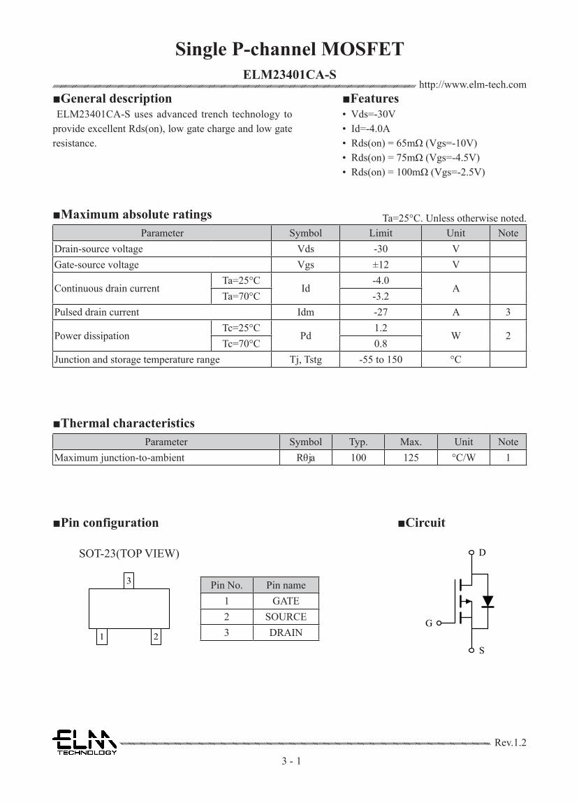
■General description ■Features
■Maximum absolute ratings
■Thermal characteristicsParameter Symbol Typ. Max. Unit Note
Maximum junction-to-ambient Rθja 100 125 °C/W 1
Parameter Symbol Limit Unit NoteDrain-source voltage Vds -30 VGate-source voltage Vgs ±12 V
Continuous drain currentTa=25°C
Id-4.0
ATa=70°C -3.2
Pulsed drain current Idm -27 A 3
Power dissipationTc=25°C
Pd1.2
W 2Tc=70°C 0.8
Junction and storage temperature range Tj, Tstg -55 to 150 °C
ELM23401CA-S uses advanced trench technology to provide excellent Rds(on), low gate charge and low gate resistance.
• Vds=-30V• Id=-4.0A • Rds(on) = 65mΩ (Vgs=-10V)• Rds(on) = 75mΩ (Vgs=-4.5V)• Rds(on) = 100mΩ (Vgs=-2.5V)
■Pin configuration ■Circuit
Single P-channel MOSFET
S
G
DSOT-23(TOP VIEW)
Pin No. Pin name1 GATE2 SOURCE3 DRAIN1 2
3
Ta=25°C. Unless otherwise noted.

2
http://www.elm-tech.com
Rev.1.2
ELM23401CA-S
3 -
■Electrical characteristics
Parameter Symbol Condition Min. Typ. Max. Unit NoteSTATIC PARAMETERSDrain-source breakdown voltage BVdss Vgs=0V, Id=-250μA -30 V
Zero gate voltage drain current IdssVds=-24V, Vgs=0V -1
μAVds=-24V, Vgs=0V, Ta=125°C -10
Gate-body leakage current Igss Vds=0V, Vgs=±12V ±100 nAGate threshold voltage Vgs(th) Vds=Vgs, Id=-250μA -0.4 -0.7 -0.9 V
Static drain-source on-resistance Rds(on)Vgs=-10V, Id=-4A 55 65
mΩ 4Vgs=-4.5V, Id=-3A 65 75Vgs=-2.5V, Id=-2A 85 100
Forward transconductance Gfs Vds=-10V, Id=-5A 15 SDiode forward voltage Vsd Is=-1A, Vgs=0V -1 VMax. body-diode continuous current Is
Vgs=Vds=0V, Force Current-2 A
Pulsed body-diode current Ism -16.4 A 4DYNAMIC PARAMETERSInput capacitance Ciss
Vgs=0V, Vds=-15V, f=1MHz830 pF
Output capacitance Coss 60 pFReverse transfer capacitance Crss 50 pFSWITCHING PARAMETERSTotal gate charge Qg
Vgs=-4.5V, Vds=-15VId=-4A
17.0 nC 4Gate-source charge Qgs 1.5 nC 4Gate-drain charge Qgd 0.9 nC 4Turn-on delay time td(on)
Vgs=-10V, Vds=-15V Id=-1A, Rgen=6Ω
5.4 ns 4Turn-on rise time tr 19.4 ns 4Turn-off delay time td(off) 45.9 ns 4Turn-off fall time tf 12.4 ns 4
Single P-channel MOSFET
Ta=25°C. Unless otherwise noted.
NOTE : 1. The value of Rθja is measured with the device on 625mm² 70μ 2 layer copper 1.6t FR4 PCB in a still air environment with Ta=25°C.2. The power dissipation Pd is based on Tj(max)=150°C, using ≤ 10s junction-to-ambient thermal resistance.3. Repetitive rating, pulse width limited by temperature Tj(max)=150°C. Ratings are based on low frequency and duty cycles to keep initial Ta=25°C.4. Pulse test : Pulsed width ≤ 300μsec and Duty cycle ≤ 2%.

3
http://www.elm-tech.com
Rev.1.2
ELM23401CA-S
3 -
■Typical electrical and thermal characteristics
Powermate Electronics Corp. Ver.1.00
3
PM3211NS30V P-Channel MOSFETsN
orm
aliz
ed G
ate
Thr
esho
ld V
olta
ge
Fig.3 Normalized Vth vs. TJ
TJ , Junction Temperature (℃)
-VG
S,G
ate
to S
ourc
e V
olta
ge (
V)
Qg , Gate Charge (nC)Fig.4 Gate Charge Waveform
Nor
mal
ized
The
rmal
Res
pons
e
Square Wave Pulse Duration (s)Square Wave Pulse Duration (s)Fig.5 Normalized Transient Impedance
-ID
,Con
tinuo
us D
rain
Cur
rent
(A
)
-VDS , Drain to Source Voltage (V)-VDS , Drain to Source Voltage (V)Fig.6 Maximum Safe Operation Area
-ID
,Con
tinuo
us D
rain
Cur
rent
(A
)
TC , Case Temperature (℃)Fig.1 Continuous Drain Current vs. TC
Nor
mal
ized
On
Res
ista
nce
TJ , Junction Temperature (℃)Fig.2 Normalized RDSON vs. TJ
Single P-channel MOSFET
Powermate Electronics Corp. Ver.1.00
3
PM3211NS30V P-Channel MOSFETsN
orm
aliz
ed G
ate
Thr
esho
ld V
olta
ge
Fig.3 Normalized Vth vs. TJ
TJ , Junction Temperature (℃)
-VG
S,G
ate
to S
ourc
e V
olta
ge (
V)
Qg , Gate Charge (nC)Fig.4 Gate Charge Waveform
Nor
mal
ized
The
rmal
Res
pons
e
Square Wave Pulse Duration (s)Fig.5 Normalized Transient Impedance
-ID
,Con
tinuo
us D
rain
Cur
rent
(A
)
-VDS , Drain to Source Voltage (V)Fig.6 Maximum Safe Operation Area
-ID
,Con
tinuo
us D
rain
Cur
rent
(A
)
TC , Case Temperature (℃)TC , Case Temperature (℃)Fig.1 Continuous Drain Current vs. TC
Nor
mal
ized
On
Res
ista
nce
TJ , Junction Temperature (℃)TJ , Junction Temperature (℃)Fig.2 Normalized RDSON vs. TJ
Powermate Electronics Corp. Ver.1.00
3
PM3211NS30V P-Channel MOSFETsN
orm
aliz
ed G
ate
Thr
esho
ld V
olta
ge
Fig.3 Normalized Vth vs. TJ
TJ , Junction Temperature (℃)
-VG
S,G
ate
to S
ourc
e V
olta
ge (
V)
Qg , Gate Charge (nC)Fig.4 Gate Charge Waveform
Nor
mal
ized
The
rmal
Res
pons
e
Square Wave Pulse Duration (s)Fig.5 Normalized Transient Impedance
-ID
,Con
tinuo
us D
rain
Cur
rent
(A
)
-VDS , Drain to Source Voltage (V)Fig.6 Maximum Safe Operation Area
-ID
,Con
tinuo
us D
rain
Cur
rent
(A
)
TC , Case Temperature (℃)Fig.1 Continuous Drain Current vs. TC
Nor
mal
ized
On
Res
ista
nce
TJ , Junction Temperature (℃)Fig.2 Normalized RDSON vs. TJ


![Schottky Barrier Diode Module · Forward Voltage Drop VF[V] F Forward Current I [A] Performance Curves Fig. 1 : Typical Forward Voltage Drop vs. Instantaneous Forward Current Fig](https://img.pdfslide.net/doc/110x75/5edcd352ad6a402d6667aa87/schottky-barrier-diode-forward-voltage-drop-vfv-f-forward-current-i-a-performance.jpg)