Embed Size (px)
Citation preview
1
Sing l e Phase Whol e C ur re nt Mete r C lass 1 .0
( 10 – 60A)
Rev No Description Prepared By Approved & Reviewed By
Date
V1.0 Whole current single phase (10 – 60A)
Arvind Rai Sandeep Kumbhar
15th April’21
2
CONTENTS
1.0 Scope................................................................................................................................................. 3
2.0 Standards ......................................................................................................................................... 3
3.0 Functional specification................................................................................................................. 3
4.0 Constructional specifications ....................................................................................................... 7
5.0 Tamper & anti-fraud detection/evidence features ................................................................... 8
6.0 General requirements ................................................................................................................... 10
7.0 Annexure 1: Display Sequence For The Parameters ................................................................ 11
3
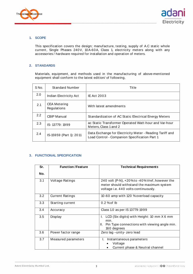
1. SCOPE This specification covers the design; manufacture, testing, supply of A.C static whole current, Single Phases 240V, 10A-60A, Class 1, electricity meters along with any accessories / hardware required for installation and operation of meters.
2. STANDARDS Materials, equipment, and methods used in the manufacturing of above-mentioned equipment shall conform to the latest edition/ of following,
S No. Standard Number Title
2.0 Indian Electricity Act IE Act 2003
2.1 CEA Metering Regulations
With latest amendments
2.2 CBIP Manual Standardization of AC Static Electrical Energy Meters
2.3 IS- 13779: 1999 ac Static Transformer Operated Watt-hour and Var-hour Meters, Class 1 and 2
2.4 IS-15959 (Part 1): 2011 Data Exchange for Electricity Meter - Reading Tariff and Load Control - Companion Specification Part 1
3. FUNCTIONAL SPECIFICATION
Sr.
No.
Function /Feature Technical Requirements
3.1 Voltage Ratings 240 volt (P-N), +20% to -40% Vref, however the meter should withstand the maximum system voltage i.e. 440 volts continuously.
3.2 Current Ratings 10-60 amp with 120 % overload capacity
3.3 Starting current 0.2 % of Ib
3.4 Accuracy Class 1.0 as per IS 13779:1999
3.5 Display I. LCD (Six digits) with Height: 10 mm X 6 mm min.
II. Pin Type connections with viewing angle min. 160 degrees
3.6 Power factor range Zero lag –unity- zero lead
3.7 Measured parameters I. Instantaneous parameters Voltage Current phase & Neutral channel
4
Sr.
No.
Function /Feature Technical Requirements
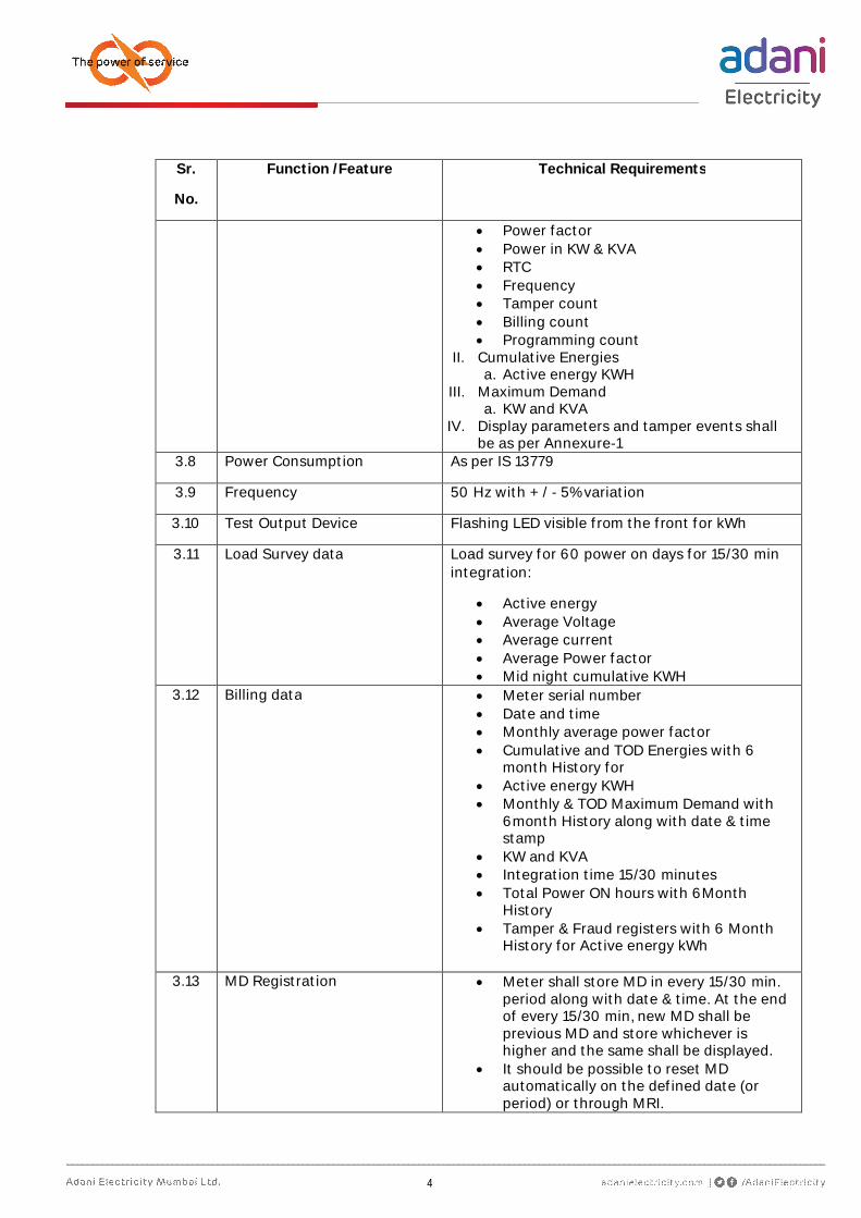
Power factor Power in KW & KVA RTC Frequency Tamper count Billing count Programming count
II. Cumulative Energies a. Active energy KWH
III. Maximum Demand a. KW and KVA
IV. Display parameters and tamper events shall be as per Annexure-1
3.8 Power Consumption As per IS 13779
3.9 Frequency 50 Hz with + / - 5% variation
3.10 Test Output Device Flashing LED visible from the front for kWh
3.11 Load Survey data Load survey for 60 power on days for 15/30 min integration:
Active energy Average Voltage Average current Average Power factor Mid night cumulative KWH
3.12 Billing data Meter serial number Date and time Monthly average power factor Cumulative and TOD Energies with 6
month History for Active energy KWH Monthly & TOD Maximum Demand with
6month History along with date & time stamp
KW and KVA Integration time 15/30 minutes Total Power ON hours with 6Month
History Tamper & Fraud registers with 6 Month
History for Active energy kWh
3.13 MD Registration Meter shall store MD in every 15/30 min. period along with date & time. At the end of every 15/30 min, new MD shall be previous MD and store whichever is higher and the same shall be displayed.
It should be possible to reset MD automatically on the defined date (or period) or through MRI.
5
Sr.
No.
Function /Feature Technical Requirements
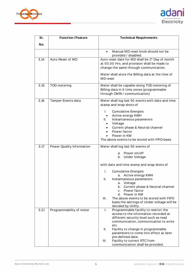
Manual MD reset knob should not be provided / disabled.
3.14 Auto Reset of MD Auto reset date for MD shall be 1st Day of month at 00.00 Hrs. and provision shall be made to change the same through communication.
Meter shall store the Billing data at the time of MD reset
3.15 TOD metering Meter shall be capable doing TOD metering of Billing data in 6 time zones (programmable through CMRI / communication)
3.16 Tamper Events data
Meter shall log last 50 events with date and time stamp and snap shots of
I. Cumulative Energies Active energy KWH
II. Instantaneous parameters Voltage Current phase & Neutral channel Power factor Power in KW
The above events to be stored with FIFO basis
3.17 Power Quality Information Meter shall log last 50 events of
a. Power on/off b. Under Voltage
with date and time stamp and snap shots of
I. Cumulative Energies a. Active energy KWH
II. Instantaneous parameters a. Voltage b. Current phase & Neutral channel c. Power factor d. Power in KW
III. The above events to be stored with FIFO basis the settings of Under voltage will be decided by Utility
3.21 Programmability of meter I. Programmable facility to restrict the access to the information recorded at different security level such as read communication, communication to write etc
II. Facility to change in programmable parameters to come into effect at later pre-defined date.
III. Facility to correct RTC from communication shall be provided.
6
Sr.
No.
Function /Feature Technical Requirements
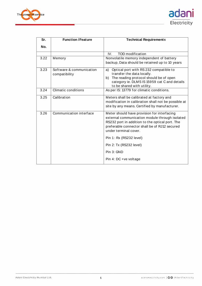
IV. TOD modification 3.22 Memory Nonvolatile memory independent of battery
backup, Data should be retained up to 10 years
3.23 Software & communication compatibility
a) Optical port with RS 232 compatible to transfer the data locally.
b) The reading protocol should be of open category ie. DLMS IS 15959 cat C and details to be shared with utility.
3.24 Climatic conditions As per IS: 13779 for climatic conditions.
3.25 Calibration Meters shall be calibrated at factory and modification in calibration shall not be possible at site by any means. Certified by manufacturer.
3.26 Communication interface Meter should have provision for interfacing external communication module through isolated RS232 port in addition to the optical port. The preferable connector shall be of RJ12 secured under terminal cover.
Pin 1 : Rx (RS232 level)
Pin 2: Tx (RS232 level)
Pin 3: GND
Pin 4: DC +ve voltage
7
4. CONSTRUCTIONAL SPECIFICATIONS
Sr.
No.
Parameters Technical Requirements
4.1 Body of Meter a) Top transparent and base opaque material polycarbonate of LEXAN 143A/943AA or equivalent grade.
b) Front cover & base should be ultrasonically welded with IP51 grade enclosure.
c) Top cover should be designed so as the internal components should not be visible.
4.2 Terminal Block Made of polycarbonate of grade 500 R or equivalent grade and shall form Integral part of the meter base, brass or copper current terminals with flat-head brass screws. All the components should be duly plated.
4.3 Terminal cover Transparent terminal cover with provision of sealing through sealing screw.
4.4 Diagram of connections
Diagram of external connections to be shown on terminal cover
4.5 Marking on name plates
Meter should have clearly visible, indelible and distinctly name plate marked in accordance with IS.
4.6 Meter Sealing Supplier shall affix one Buyer seal on side of Meter body as advised and record should be forwarded to Buyer.
4.7 Guarantee 5 Years.
4.8 Insulation A meter shall withstand an insulation test of 4 KV and impulse test at 8 KV
4.9 Resistance of heat and fire
The terminal block and Meter case shall have safety against the spread of fire. They shall not be ignited by thermal overload of live parts in contact with them as per the relevant IS 13779.
8
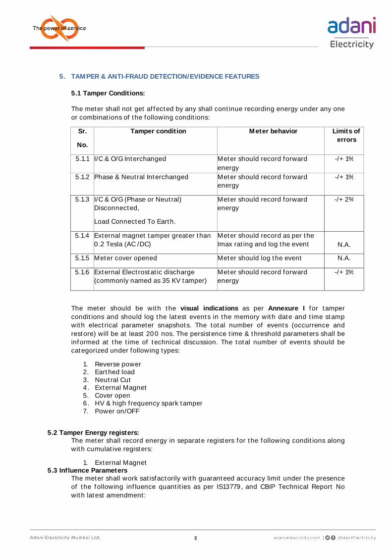
5. TAMPER & ANTI-FRAUD DETECTION/EVIDENCE FEATURES
5.1 Tamper Conditions:
The meter shall not get affected by any shall continue recording energy under any one or combinations of the following conditions:
Sr.
No.
Tamper condition Meter behavior Limits of errors
5.1.1 I/C & O/G Interchanged Meter should record forward energy
-/+ 1%
5.1.2 Phase & Neutral Interchanged Meter should record forward energy
-/+ 1%
5.1.3 I/C & O/G (Phase or Neutral) Disconnected,
Load Connected To Earth.
Meter should record forward energy
-/+ 2%
5.1.4 External magnet tamper greater than 0.2 Tesla (AC /DC)
Meter should record as per the Imax rating and log the event
N.A.
5.1.5 Meter cover opened Meter should log the event N.A.
5.1.6 External Electrostatic discharge (commonly named as 35 KV tamper)
Meter should record forward energy
-/+ 1%
The meter should be with the visual indications as per Annexure I for tamper conditions and should log the latest events in the memory with date and time stamp with electrical parameter snapshots. The total number of events (occurrence and restore) will be at least 200 nos. The persistence time & threshold parameters shall be informed at the time of technical discussion. The total number of events should be categorized under following types:
1. Reverse power 2. Earthed load 3. Neutral Cut 4. External Magnet 5. Cover open 6. HV & high frequency spark tamper 7. Power on/OFF
5.2 Tamper Energy registers: The meter shall record energy in separate registers for the following conditions along with cumulative registers:
1. External Magnet 5.3 Influence Parameters
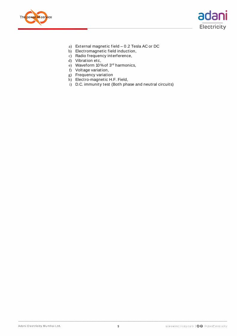
The meter shall work satisfactorily with guaranteed accuracy limit under the presence of the following influence quantities as per IS13779, and CBIP Technical Report No with latest amendment:
9
a) External magnetic field – 0.2 Tesla AC or DC b) Electromagnetic field induction, c) Radio frequency interference, d) Vibration etc, e) Waveform 10% of 3rd harmonics, f) Voltage variation, g) Frequency variation h) Electro-magnetic H.F. Field, i) D.C. immunity test (Both phase and neutral circuits)
10
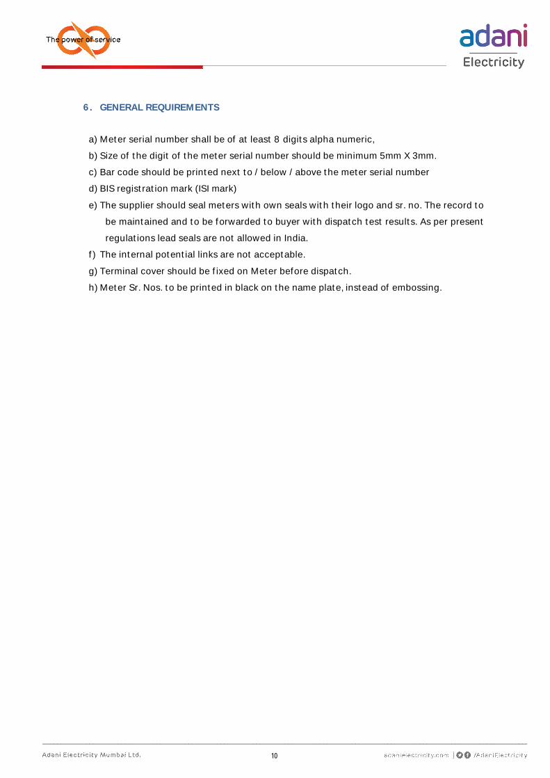
6. GENERAL REQUIREMENTS
a) Meter serial number shall be of at least 8 digits alpha numeric,
b) Size of the digit of the meter serial number should be minimum 5mm X 3mm.
c) Bar code should be printed next to / below / above the meter serial number
d) BIS registration mark (ISI mark)
e) The supplier should seal meters with own seals with their logo and sr. no. The record to
be maintained and to be forwarded to buyer with dispatch test results. As per present
regulations lead seals are not allowed in India.
f) The internal potential links are not acceptable.
g) Terminal cover should be fixed on Meter before dispatch.
h) Meter Sr. Nos. to be printed in black on the name plate, instead of embossing.
11
7. Annexure-1
7.1 The meter shall have LED i.e. Cal Pulse LED of RED color in front display of meter.
7.2 Display Parameter Sequence
a) Auto Mode (Default Display)
Cumulative Total KWh (Cumulative KWh to be displayed continuously without decimal)
Note: In case of occurrence of meter “Cover Open” tamper, the message “Cover Open” and Cumulative Total KWh shall be displayed in toggle mode (6 seconds).
b) On Demand Display
With pushbutton the following parameters should be displayed;
1) LCD Test 2) RTC Date 3) RTC Time 4) Instantaneous Voltage 5) Instantaneous Phase Current 6) Instantaneous Neutral Current 7) Power Factor 8) High Resolution Cumulative Total KWh for dial test.(00.0000 format) 9) Absolute energies 10) Cumulative Energies (Import mode) 11) Cumulative Energies (Export mode) 12) Current MD KW (Import & Export) 13) Current MD KVA (Import & Export) 14) Current MDs in KW occurrence date and time 15) Current MDs in KVA occurrence date and time 16) Last month billing date 17) Last month billing KWh (Import & Export) (H1) 18) Last month billing MD in KW (Import & Export) (H1) 19) Last month billing MD in KVA (Import & Export) (H1) 20) Last month billing MDs KW occurrence date and time (H1) 21) Last month billing MDs KVA occurrence date and time (H1) 22) Last month TOD energies(H1) 23) Last month TOD MDs with date & times(H1) 24) Repeat sr. no 16-23 for Last 3 histories
Note: The meter display should return to Default Display mode (mentioned above) if the ‘push
button’ is not operated for more than 6 seconds.