Embed Size (px)
Citation preview
1
Abstract—BC Hydro recently developed a radial 287 kV
Northwest Transmission system which includes a long (340 km) line. After the terminal station it connects to two shorter lines. Short time after when the system went into the service, the long line experienced multiple line-to-ground faults due to icing and it led to single-phase trip protection and auto-reclose operations. During open-pole condition phase duration, the floating phase on the short lines experienced unsafe over-voltages causing transformer and reactor protection trips. This paper will use disturbance records to explain the sequence of events and present the detailed waveform analysis. It was found that the sensitive phase-to-phase fault protection operated on the shunt reactor. The transformer protections operated on excessive magnetizing current due to the differential restraint element fifth harmonic currents dropping below the setting threshold (35% on three phases). It appeared that the harmonic restraint dropped on higher voltage due to excessive saturation causing flux to transfer from transformer core to tank. The disturbance has been simulated with EMTP and this helped to identify the causes of the over-voltage. The paper will also discuss the simulation results and some recommend solutions to avoid re-occurrence of the over-voltages problem.
Index Terms — Single-Pole Operation, Temporary Over-Voltage, Transformer over-excitation
I. INTRODUCTION
he BC Hydro transmission system, in a remote corner of the province, had a sizeable addition brought into service
near the end of 2014. To spur economic activity in the region a series of new transmission lines were constructed to accommodate both non-utility generation and large industrial loads. The main 287 kV transmission line to the area is very long and had significantly more faults than anticipated in months following the first energization. The protection systems had been very dependable during all the faults in the initial months and in the time since then as well. The security of the relaying system has also been quite good. It was tested though under a severe unintended operating condition for a fault that occurred on January 7th 2015. This paper outlines how multiple faults that day left the system in the unintended operating configuration. This condition resulted in approximately 1.7 pu voltage at multiple substations. Next the paper will discuss how protection relaying in the region responded while the system was operating in a critical state. Three protection relays operated while there was no fault
Submitted September 2015 Mukesh Nagpal e-mail BC Hydro, Burnaby, BC V3N 4X8, Canada [email protected]
within their protection zones. The paper includes detailed steady-state and high frequency analysis to re-create the conditions witnessed in the field. Finally, the paper will briefly describe potential remedies to prevent further abnormal conditions in the system.
II. BC HYDRO SYSTEM
BC Hydro, the third largest utility in Canada, possesses major hydro-electric generation assets. These resources, primarily located in the northern (Peace River) region of the province and in the south eastern (Columbia River) region, are remote from the south-west corner of the province where most of the demand for electricity is concentrated.
A. Northwest Transmission System
Figure 1 shows geographic one-line diagram of the Northwest Transmission System (NTL). It consists of a new 287-kilovolt (kV), 340 km long transmission line, 2L102, connecting the existing BC Hydro Skeena (SKA) Substation near Terrace with a new substation – Bob Quinn (BQN) near Bob Quinn Lake.
The system was expanded to provide a secure interconnection point for clean generation projects via 39 km long 287 kV transmission circuit 2L379. The three connected non-utility generating clusters are Forrest Kerr (FKR), and Volcano Creek (VOL), all on the Iskut River near Forrest Kerr Creek, north of Stewart in northwestern BC. The total output from these clusters would be 305 MW from run of river generation units. These generators supply clean electricity to support development in the area.
The system is also serving the industrial and residential load via a three terminal 287 kV 110 km long transmission line 2L374. The transmission system one - line diagram including existing BC Hydro northern region transmission network, the NTL, new Bob Quinn substation and IPP generation and transmission system is shown in Figure 2. The area can now reduce greenhouse gas emission by enabling communities now relying on diesel generation to connect to the BC Hydro transmission grid as well.
B. Detail of a 287 kV Line in Northwest System
Figure 3 shows a simplified one-line diagram showing circuit 2L102, which was involved in the incident. As shown in Figure 1, this line is the only transmission path between Skeena (SKA) Substation and Bob Quinn (BQN) switching stations. The line is 340 km long and is fully transposed. There is an optical ground wire (OPGW) cable run between the tops of high voltage electricity towers. The optical fiber within the
Mukesh Nagpal, Terry Martinich, Ska-Hiish, Tyler Scott, Gurinder Hundal and Apollo Zhang BC Hydro, BC, Canada
Single-Pole Operation Leads to Hazardous Over-Voltage on Adjacent Lines
T

2
cable is used for high speed protection and SCADA functions. Tower construction, conductor data along with the line parameters determined from the construction data are listed in Appendix I. There is 35% series compensation at the BQN end of line and 72% positive sequence shunt compensation using two reactors at SKA and one at BQN. The shunt reactors at SKA (2RX1 & 2RX2) are fixed and the one at BQN (2RX231) is switchable.
2L102 is protected by modern microprocessor-based relays with a high speed, sub-cycle, current differential scheme. The line breakers are rated as having a three cycle interrupt time. Therefore overall fault clearing time is less than four cycles for all bolted faults. This speed is within the performance target specified in NTL system planning studies.
Figure 1: BC Hydro Northwest Transmission System Geographical Map.
Figure 2: Northern Region BC Hydro Transmission System One-Line Diagram.
To maintain the system stability, single-shot high speed automatic reclose is attempted after line trips. The reclose scheme is designed to initiate single-pole trips for single-phase-to-ground faults and three-pole trips for all multi-phase faults. The SKA bus is the lead or master end for auto-reclose and the associated breakers 2CB7 and 2CB8 are equipped with point-on-wave (POW) closing to minimize the line pickup transients. 2CB7 is the first breaker to close followed by 2CB8. The BQN bus is the follow end with 2CB3 closing first and 2CB4 closing second.

3
Figure 3: Simplified 2L102 One-Line Diagram – NTL System.
III. EVENT DESCRIPTION
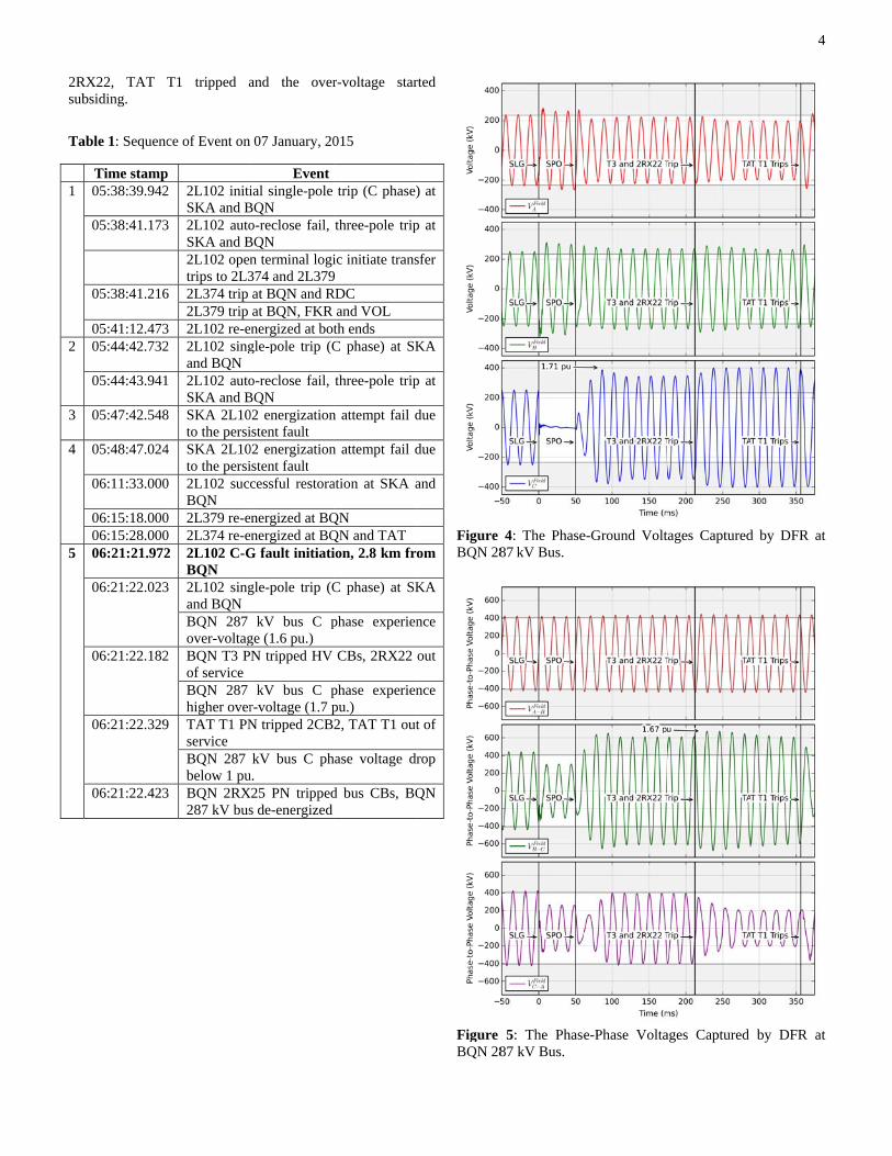
This section is divided into two subsections. The first section describes a series of incidents which includes five individual faults at different times and the nature of these faults. The events with time stamps are listed in sequence in Table 1. The second subsection focuses specifically on the fifth event. During this event the entire system north of BQN experienced significant over-voltage on one phase. The subsection presents detailed analyses of the waveforms recorded by the high speed digital fault recorders during this incident.
A. Overview of the Incident
Table 1 lists the sequence of events for this series of events. On 7th January, 2015 at 05:38:39 PST, the first Phase C-to-ground fault occurred on 2L102 about 2 km from BQN station. The line protection responded correctly to trip single-pole (Phase C) in three cycles and executed an auto-reclose after the one second open pole interval. The fault was caused by an OPGW wire sagging under the heavy snow accumulation on the wire. Since the sagging wire reduced clearance between the phase conductor and ground wire, it took longer for the fault to self-extinguish than expected. Hence, the line was auto-reclosed onto a persistent fault. The failure of auto-reclose resulted in a three-pole trip at both line
terminals (SKA and BQN). Referring to system one-line diagram in Figure 2, 2L102 protection operation keys direct transfer trip (DTT) to the downstream line protection relays, 2L374 and 2L379, to isolate the remote generation and transmission customer load upon disconnection from BC Hydro integrated system. On receipt of DTT, 2L374 tripped at BQN terminal and RDC entrance circuit breakers. Similarly, 2L379 tripped BQN terminal as well as FKR and VOL entrance circuit breakers. Note that RDC load remained disconnected and 2L379 remained open-end at FKR and VOL throughout the rest of events that morning.
A second Phase C-to-ground fault occurred at 05:44:42.732 PST; shortly after BC Hydro control center restored 2L102. The control center had not yet restored 2L374 and 2L379. Similar to the first event, the line tripped single-pole and then ended up tipping three-pole trip due to the auto-reclose failure. The third and fourth events are failed attempts to energize 2L102 from SKA station by BC Hydro control center. They both failed due to a persistent fault on the line.
Before the fifth event, BC Hydro control center was in the process of restoring the Northwest Transmission system. It was restored to a point such that 2L102 was fully restored at both ends, 2L374 energized from BQN to TAT and open ended at RDC, and 2L379 energized at BQN but open ended at FKR and VOL. In this system configuration, 2L102 from SKA is the only source in the Northwest system. A Phase C-to-ground fault on 2L102 reoccurred at 06:21:21.972 PST at the same location as the previous events - 2.8 km from BQN. Breakers associated with Phase C of 2L102 were tripped by the protection. Because non-utility generation was not reconnected after the previous fault, opening of Phase C breakers on 2L102 led to loss of source on that phase for all three circuits in the Northwest Transmission system. In absence of regulated source on Phase C, the voltage on that phase in the BQN-2L374-2L379 sub-system experienced a temporary over-voltage exceeding 1.7 pu. The high voltage caused one shunt reactor and two transformer protections to operate. This event is the main subject of analysis being reported on this paper. The remaining paper will discuss protection response during this event, analytical simulations replicating the event and methods to avoid its reoccurrence.
B. Over-Voltage Waveforms
Figure 4 shows three phase-to-ground voltages captured by the digital fault recorders (DFR) at the BQN bus. Phase C-to-ground voltage exceeded 1.6 pu within two cycles after opening of Phase C beakers on 2L102. It is interesting to note that, during the temporary over-voltage (TOV), Phase B-to-ground and the C phase-to-ground voltages are nearly 180 degrees out-of-phase. Figure 5 shows phase-to-phase voltages which indicate that the BQN T3 delta-connected winding between Phases B and C was subjected to the over-voltage and saturation of that winding. This over-voltage resulted in BQN T3 tripping in about 10 cycles after the single-phase opening. Since BQN T3 and 2RX22 share the tripping zone, 2RX22 was disconnected from the system at the same time. This lead to the voltage increasing yet again, this time to more than 1.7 pu. About 8.5 cycles after tripping of BQN T3 and reactor
2Rsub
Ta
1
2
3
4
5
RX22, TAT bsiding.
able 1: Sequenc
Time stamp05:38:39.942
05:38:41.173
05:38:41.216
05:41:12.47305:44:42.732
05:44:43.941
05:47:42.548
05:48:47.024
06:11:33.000
06:15:18.00006:15:28.00006:21:21.972
06:21:22.023
06:21:22.182
06:21:22.329
06:21:22.423
T1 tripped a
ce of Event on
p 2 2L102 initi
SKA and B3 2L102 auto
SKA and B2L102 opentrips to 2L3
6 2L374 trip 2L379 trip
3 2L102 re-e2 2L102 sing
and BQN 1 2L102 auto
SKA and B8 SKA 2L10
to the persi4 SKA 2L10
to the persi0 2L102 succ
BQN 0 2L379 re-e0 2L374 re-e2 2L102 C-G
BQN 3 2L102 sing
and BQN BQN 287 over-voltag
2 BQN T3 Pof service BQN 287 higher over
9 TAT T1 PNservice BQN 287 below 1 pu
3 BQN 2RX287 kV bus
and the over
07 January, 20
Event ial single-pole
BQN o-reclose fail,
BQN n terminal logi374 and 2L379at BQN and Rat BQN, FKR
energized at botgle-pole trip (C
o-reclose fail, BQN 02 energizationistent fault 02 energizationistent fault cessful restora
energized at BQenergized at BQG fault initiati
gle-pole trip (C
kV bus C pge (1.6 pu.) N tripped HV
kV bus C pr-voltage (1.7 pN tripped 2CB
kV bus C phu. X25 PN tripped
s de-energized
r-voltage star
015
trip (C phase)
three-pole trip
ic initiate trans9 RDC
and VOL th ends C phase) at SK
three-pole trip
n attempt fail d
n attempt fail d
ation at SKA a
QN QN and TAT ion, 2.8 km fro
C phase) at SK
phase experien
CBs, 2RX22
phase experienpu.) 2, TAT T1 out
hase voltage dr
d bus CBs, BQ
rted
) at
p at
sfer
KA
p at
due
due
and
om
KA
nce
out
nce
t of
rop
QN
Figure BQN 28
Figure BQN 28
4: The Phase87 kV Bus.
5: The Phase87 kV Bus.
e-Ground Volt
e-Phase Volta
tages Captured
ages Captured
4
d by DFR at
by DFR at

5
IV. PROTECTION AND CONTROL DESCRIPTION
In two months following Northwest Transmission system energization, 2L102 had several phase-to-ground faults and the protection performed correctly during all faults. Previous sections detailed how the system ended up in an undesirable operational state on the morning of 7th January 2015.
The following protection section will detail the protection operations in the NTL system that morning besides the 2L102 operations. It will also discuss the protection operations that did not occur. Section V will discuss the measures taken to quickly take action in the protection system to reduce the chance of a high temporary over-voltage in the future.
A. Duration of Over-Voltage Condition
The 2L102 line protection had single-phase tripping (SPT) enabled on January 7th, which opens only the faulted phase for any single-phase-to-ground fault. If the fault persists when the open phase is closed (unsuccessful reclose), then the line protection would open all phases with three-phase tripping (3PT) logic, and send direct transfer trips to open entrance breakers of RDC, FKR and VOL. The single-phase open interval of the line is approximately 60 cycles (1 second). The first phase-to-ground fault occurred at 5:38 AM and it was persistent so, a direct transfer trip was sent to RDC, FKR, and VOL taking them offline for the remainder of this time period. During the 6:21 AM event 2L102 line protection detected the single-phase-to-ground fault. During the approximately 1 second single-phase open (SPO) period, a number of addition protection operations occurred, some unexpectedly.
B. BQN Transformer T3 Protection Operation
BQN T3 is a 10 MVA transformer with an HV delta winding and an LV wye winding. The transformer serves a fourth harmonic filter bank and the station service transformer at BQN substation.
As shown in Figure 3, the voltage between Phase B and C became very high (more 1.6 pu) during open pole period. It saturated the delta winding of BQN T3 connected between the two phases. Figure 6 shows the disturbance records from the transformer differential relay. Three analog traces on top are three-phase line currents processed by the 60-Hz digital filter embedded in the relay. Two analog traces in the middle of the figure are fifth harmonic frequency content relative to the fundamental frequency in differential current measured by the relay for the B and C phases. In bottom part of the figure, digital traces are illustrating responses various relay elements to the differential currents measured when the B-to-C winding was overexcited by over-voltage. To illustrate distorted nature, Figure 7 shows the unfiltered analog traces of the line currents into the transformer. T3 primary (287 kV side) currents demonstrate that, with harmonic distortion considered, these currents were about 3 times the 20 Arms rated primary current. Though not shown, negligible currents were coming out of the transformer low-voltage windings confirming that the high-side currents were transformer magnetizing currents. In Figure 6 and Figure 7, Phase B and C line currents were practically 180º out-of-phase which confirmed the saturation
of the B-to-C winding transformer core. There was negligible line current in Phase A.
The magnetizing currents on high-side appeared as Phase B and C differential or operate currents. However, the relay operation was initially blocked for approximately three cycles by the 2nd and 5th harmonic elements as shown by digital traces in Figure 6. The relay was set to restrain the trip operation when the 2nd harmonic component of the differential current exceeded 15% of the fundamental frequency current in one or more phase. Likewise, 5th harmonic restraint was set to 35%. Once the 2nd and 5th harmonic current content dropped beyond their individual setting threshold, the relay tripped.
The BQN T3 tripping zone trips 287 kV circuit breakers 2CB2 and 2CB3. This protection operation also tripped reactor BQN 2RX22 as collateral since they share a tripping zone. It is likely that BQN 2RX22 would have eventually tripped as well if given more time.
Figure 6: From the BQN T3 Protection Event Report, Showing the Filtered Primary Currents.
Figure 7: From the BQN T3 Protection Event Report, Showing the Unfiltered Transformer Magnetizing Currents.
C. TAT Transformer T1 Protection Operation
TAT T1 is a 16.6 MVA transformer with an HV wye winding and an LV wye winding. The transformer has a buried delta tertiary winding. The transformer serves the small amount of distribution load in the area at 25 kV.
TAT T1 was also exposed to high voltages well above the knee point voltage of the saturation characteristic. T1 conducted a relatively high current for 8 cycles before its protection tripped the transformer. From the event report, the

6
filtered primary currents are shown in Figure 8 and the unfiltered currents appear in Figure 9. The maximum instantaneous currents (Phase B and C) were about 170 A peak, due to severe harmonic distortion. As a comparison, the rated primary current is 33 Arms (47 A peak).
Like BQN T3, a high percentage of 5th harmonic current blocked the transformer from operating instantaneously when it began to saturate from the high voltage. This event report also shows the 5th harmonic current dropping below 35% and tripping shortly afterwards. Compared to BQN T3, this transformer took nearly 8 cycles longer to saturate to the point where 5th harmonic current dropped below the inrush threshold.
The unfiltered event report shows that the harmonic current started to reduce while the fundamental current increased four cycles after the relays event report was triggered. This aligns with the tripping of BQN T3 and RX22 and the subsequent voltage rise that was recorded in the area. The even higher voltage drove the TAT transformer core deeper into saturation causing the magnetizing flux to leak out of the core and setting up eddy currents in the non-laminated parts of transformer. As a result, the fifth harmonic current dropped relative to the fundamental frequency component and contributed to transformer tripping. Similar to other transmission and distribution transformers in BC Hydro, the transformers in the new NTL system were neither equipped with over-voltage nor Volt-per-Hertz protection. Trips by the differential protection saved the transformers from possible damage.
Figure 8: From the TAT T1 Protection Event Report, Showing the Filtered Primary Currents
Figure 9: From the TAT T1 Protection Event Report, Showing the Filtered Primary Currents
D. BQN Reactor 2RX25 Protection Operation
BQN 2RX25 is a 20 MVA oil filled reactor. The primary purpose of the reactor is to compensate line charging capacitance for 2L374.
The reactor protection consists of primary high impedance differential protection as well as primary and standby phase and ground over-current protection. The differential protection is able to detect phase-to-ground faults and trip instantaneously. It is unable to detect turn to turn faults though. We deploy two sets of over-current protection to ensure we have redundant protection to detect turn to turn faults with the reactor.
The reactor was subject to a 1.7 pu voltage, which translates to a higher than 1.7 pu current due to saturation. Currents observed during the over-voltage were 3 pu and were sufficient to activate the inverse-time over-current protection. Unlike the transformers discussed earlier there was no differential current in the reactor. All current entering the reactor left the corresponding low voltage terminal of the reactor. This reactor has a phase over-current element set to pick-up at 1.2 times nominal phase current with an inverse time tripping element. It was initially assumed that this was the element that tripped 2RX25. Upon investigating the event reports from the protection relays it was determined that the phase over-current element did not actually trip the reactor. BC Hydro has devolved a specialized element to detect phase-to-phase faults deep within multi-phase reactors. A phase-to-phase fault will result in an increase in phase-to-phase current along with a corresponding decrease in phase-to-phase voltage. Our element is looking for a 25 percent increase in current along with and 20 percent decrease in phase-to-phase voltage. Figure 10 is an event report for the reactor over-current protection. Element 50BCS is the Phase B to C over-current and Element 27CA is the Phase A to C under-voltage element. Element SV5T is an 8 cycle pick-up timer required for the phase-to-phase fault detector to operate.

7
Figure 10: From the BQN 2RX25 Protection Event Report.
The unfiltered event report in Figure 11 shows significantly less harmonic current than either of the two transformers experienced. More than 1.7 pu of phase-to-ground temporary over-voltage was present at the transformer terminal at the time of protection operation. The slope of the flux-current characteristic of 2RX25 in the fully saturated region is significantly higher than that of the transformer (air-core inductance). Hence, the smaller harmonic content in the reactor currents.
Figure 11: From the BQN 2RX25 Unfiltered Event Report.
E. Observations on Protection Operations
The operation of the protection systems helped to reduce the severity of the over-voltage in the area. This is especially true following the clearing of TAT T1. Figure 12 shows an immediate decrease in voltage following TAT T1 breakers opening.
It is also interesting to review the breaker clearing times for these operations. The three protection operations were nearly uniform in their breaker clearing times as shown in Figure 12. All the breakers in this system are rated at a 2.4 cycle nominal clearing speed. In actual operation under these conditions the clearing time recorded by the protection relays was 6 cycles – more than double the rated time. All breakers are rated at 362 kV, but were exposed to voltages above the voltage rating. All currents were well below the breaker rated interrupting current of 40 kA. Higher than nominal breaker interrupting times are expected at the lower fault currents. It must be taken into account for breaker failure timer settings. An event report from the BQN 2L374 protection relay nearly capture the entire
event with filtered currents and voltages. The clearing points of various protections are easily identified with changes in currents and voltages at the BQN terminal.
Figure 12: BQN Composite Protection Operations.
V. SYSTEM ANALYSIS
A. Simplified Steady-State Analysis
Simplified steady-state analysis for the unbalanced open phase conditions is given in this section to estimate the natural resonance frequency provided by the open phase condition. When the natural resonance frequency is near the power frequency (60Hz), it is highly possible [1-5] that this will lead to the over-voltage phenomenon during the incident reported in this paper.
Figure 13 shows the three-phase circuit diagram representing BQN-2L374-2L379 sub-network. For simplicity, there are a few assumption made to the network. They are as follows:
Assume the healthy phase voltages (A and B) are equal and 120 degree apart
Assume both lines are fully and properly transposed Ignore non-linear effects, i.e. surge arrestor conduction,
transformer or reactor magnetic saturation, or corona effects
Lump phase-to-ground capacitance and interphase capacitance on both lines as one set of capacitance
Ignore the TAT primary to secondary coupling since the load is very small

8
Figure 13: Simplified BQN-2L374-2L379 sub-system with C phase open.
The symbols used on Figure 13 are self-explanatory. The shunt reactor 2RX25 at BQN can be represented by the shunt inductance (Lg). The transformer TAT T1 leakage impedance between Primary winding and Tertiary Winding can be represented by the inductance LT. For each transmission line, the phase-to-ground capacitance (Cg) and the inter-phase capacitance (Cm) can be obtained from the line parameters – Positive Sequence Capacitance (C1) and Zero Sequence Capacitance (C0):
301 CC
Cm
, 0CCg
The two transmission lines 2L374 and 2L379 are in parallel. Therefore, their inter-phase mutual capacitance (Cm) and ground capacitance (Cg) can be lumped together and be represented by a total Cm and Cg.
Figure 14 (a) shows the equivalent network representation for one open phase condition in Figure 13. It can be further simplified by finding its Thevenin Equivalent circuit which is shown in Figure 14 (b). The equivalent circuit is a simple LC circuit, and the natural resonance frequency of this circuit can be derived as follows:
Hz
LL
CCLLf
Tg
mgTg
6.62)2(
2
1
The simplified circuit natural frequency is 62.6Hz which is very close to the power frequency of 60Hz. With the consideration of the transformer saturation, the leakage impedance will become larger and hence change the resonance frequency still closer to 60Hz. It is highly possible that the resonance phenomenon could result in the open-pole voltage rising above the source voltage level (1p.u.). Therefore, it gives a general indication of how the system voltage could possibly behave in the open pole condition.
Tg
Tg
LL
LL
Figure 14: Simplified Thevenin Equivalent Circuit.
This simplified analysis is only for the purpose of understanding. It does not include non-linear components which will be considered in the following sections for more accurate modelling and simulation.
B. EMTP Linear Analysis with and without TAT T1
To establish the dominant causes of the high over-voltages during the 2L102 SPO period, all the nonlinear effects (arrestor conduction, magnetic saturation, and corona losses) are neglected; only the linear effects are simulation. Through a process of elimination, each transformer and reactor is removed one by one and the 2L102 SPO period is simulated. The C phase voltages are then observed. It was determined that TAT T1 was the dominant cause of the high C Phase over-voltages. See Figure 15 for simulation with TAT T1 as well as without TAT T1.
Other than the opening of 2L102 Phase C at BQN 3 cycles after fault inception, no other switching occurs during the simulations. For simplicity, in the simulations the small station service load supplied from BQN T3 was neglected and the TAT distribution load was assumed to be only 300 kW. Since the instantaneous Phase C-to-ground voltage is of primary interest, only that phase is plotted.
a) Linear Case with TAT T1
This case assumes the same initial conditions as on 7th January Phase C fault near BQN and the same SPO switching times. All shunt reactors and the BQN and TAT transformers are in service. As can be clearly seen in Figure 15 (a), as soon as 2L102 Phase C is disconnected at BQN, the magnitude of the fundamental frequency voltage in Phase C of the BQN-FKR-RDC system escalates dramatically, to more than 5 pu after six cycles. This indicates the presence of a near fundamental frequency resonance for this open-phase condition. The Phase C voltage waveform is actually the first part of a ring-down waveform. The waveform results from the modulation of two frequencies, one being the power frequency or forcing frequency and the other being the natural (or resonant) frequency of the circuit. Capacitive and magnetic coupling to two phases energized from the grid provides the sustained source at power frequency. The transient resonant response of Phase C will be shown to be close to 60 Hz. Increasing the EMTP simulation time shows a beating effect in the waveform where the modulation would have eventually reached a minimum voltage (less than 1 pu) and then repeated but with reduced magnitudes.

b)
FgroserFigprefrewitinsTha dtha
Fig
C.
FlinreckVdisas neacycWiintaro20botTOT1
Linear Case
For this EMTPounded-star anrvice. The Phagure 15 (b) sheceding case, equency of theth TAT T1 anstantaneous ovhis case clearlydominant role iat occurred for
gure 15: EMTP
EMTP Non-L
Figure 16 comnear effects tocorder (DFR) a
V instantaneousplayed in solidotted lines. Aar BQN at T =cles later andithin 1.5 cycleto a high TOV,ound 1.67 pu f0 ms BQN T3th T3 as well
OV on Phase C trips off.
without TAT T
P simulation, Tnd delta tertiaase C phase-tohow a dramatof the over-v
e modulated wnd BQN T3 ouver-voltage ony demonstrates in producing ththe January 7,
P Linear Analy
Linear Analysis
mpares the EMo the recordedat the BQN enus C Phase vd lines while t
A Phase C-to-g0 and the Pha
d SKA Phase es, Phase C-to, with an initiafollowed by a 3 protection opas 2RX22. Th
C to about 1.7
T1
TAT T1 (HV gary) is assumeo-ground voltagtic reduction,
voltages duringwaveform is simut of service bnly marginally
that TAT T1 mhe high tempor 06:21:21 SPO
ysis with and w
s with TAT T1
MTP simulatiod data from nd of the 2L37voltage (phasthe simulated vground fault ocse C of the lineC opens one-
o-ground voltagal 2 cycles of a
TOV of aboupens 2CB2 andere is an imme1 pu, which pe
grounded-star Led to be out ge waveformscompared to
g SPO. The bmilar to the c
but the maximu exceeds 1.0must have playrary over-voltagO event.
without TAT T
on with the nothe digital fa
79. The DFR 2e-to-ground) values are shoccurred on 2L1e at BQN open-half cycle latge at BQN go
an over-voltageut 1.6 pu. At Td 2CB3 and trediate increaseersists until TA
LV of
of the
beat ase um pu. yed ges
T1.
on-ault 287 are
own 102 ns 3 ter. oes e of T = rips e in AT
The correspodots sup287 kVvoltage waveforthe Relaof the eRMSE phase Cconsideoffsets. field rec0.9673 TherefokV sysinvestig
Figure
The 2metal oabsorptifor this simulatiinstantacurrentsenergy the timvoltage,capabili
EMTP simulonding to the s
uperimposed onV voltages. A
waveforms arrms. The goodative Mean Squerror divided bfor phase A i
C is 7.39%. Theration the erro
In addition, thcording and sifor A phase,
ore, the EMTPstem has beengations.
16: EMTP No
228kV rated soxide arresterion capability arrester is therion of the 2SA
aneous voltages during the Saccumulation
me that TAT T, the arrester hity. Once a me
lation of the sequence of evn the three plo
As can be seere in good agr
dness of fit of tquared Error (Rby the RMS os 2.10%, for P
he RMSE is usor magnitude whe Pearson corrimulation valu, B phase, an
P model of then verified an
on-linear Analy
surge arrestersrs rated IEC
of around 10 refore about 2.A25 Phase C e across the
SPO. As can boccurs after T
T1 trips off, enhas absorbed 1.etal oxide arre
phase-to-grouvents is shown aots of the mea
en, the simulareement with the model is de
RMSE), which of the field recPhase B is 1.2ed because it c
while considerirelation coeffices are 0.9899, nd C Phase, e linear and nond is suitable
ysis with TAT
s 2SA25 on BQClass 4 withkJ/kVr. The r
.3 MJ. Figure 1energy accumarrester, and e seen, the hig
T3 and 2RX22nding the temp.94 MJ, or 84 pester is subject
9
und voltages as a series of asured BQN
ated Phase C the recorded etermined by is the square cording. The 24%, and for can take into ing the phase cients for the 0.9944, and respectively. onlinear 287
for further
T1.
QN 2B5 are h an energy rated energy 17 shows the mulation, the
the arrester ghest rate of
2 trip off. By porary over-percent of its ed to energy

absloscom
FigEn
ter
A. Imphsoltrip Ad
Di
sorption abovesses may resumponents and
gure 17: EMTnergy Absorptio
VI
This section drm over-voltage
Immediate Acmmediately afte
ase trip and lutions could bp and auto-recl
dvantages:
This solutiontemporary investment in
sadvantages:
Any single-lof the Nortloss of reveChris Mine, of service to
e its rating, theult in thermalthe arrester fai
TP Simulation on.
I. MITIGATION
describes the e mitigation al
ction er 7th January
reclose modbe developed. lose three-pole
n prevented a over-voltage
n hardware and
line to ground fthwest Transmenue for the loss of station distribution cu
e internal heatil runaway ofils.
of BQN Surge
N ALTERNATIV
short-term, internatives.
2015 incidende was disabl
The 2L102 ree for all detecte
repeat of the event with
d communicati
fault causes a cmission system
non-utility geservice at BQN
ustomers.
ing due to enerf the zinc ox
e Arrestor 2SA
VES
nterim, and lon
nt, 2L102 singled until furthelays were set
ed faults.
January 7th hhout additioions.
complete breakm, disruption a
nerator and RN, as well as l
rgy xide
A25
ng-
gle-her t to
igh onal
kup and Red oss
B. LonAnalytigeneratiof a sev2L102. to prove
It wadynamiloading testing MW infchosen NUG arconnectsingle-p
EMP18. A fpossiblyenable/dThis marelay ba Advanta
Disadva
ng Term Solutioical studies iion and/or loadvere over-voltaFaults between
e these results.as decided thatcally controll
g at BQN substit was decideflow into BQNas this guaran
are operating ation from the 2pole tripping onPT studies analfurther long tey use remedisable single-ay achieve moased solution.
ages:
This solutioadditional moperational in
antages:
This solutioresonant circ
on identified thad in the BQN sage during sinn October 201 t single-pole trled by monitation. To simp
ed to focus solN substation. Antees at least tat their full ou2L379 to 2L10n and off. lyzing this solerm solution iedial action -pole tripping bore dependabil
on does not rmajor equipmn the least time
on does not cuit.
at if there isystem then thengle-pole open 4 and January
ripping of 2L1toring real tplify protectionlely on monito
A threshold of two generatingutput. A simple02 protection re
lution are shows being explor
scheme conbased on area plity than a pur
require the inment, is expee and at the lea
detune the
10
is sufficient ere is no risk intervals on 2015 helped
02 would be time system n setting and oring 2L379 23 MW was
g units at the e hard wired elays toggles
wn in Figure red that will ntrollers to power flows. re protection
nvestment in ected to be ast cost.
fundamental

Fig2L
C. F
deldesin Ad
Di
gure 18: EMTL379 and Single
Equipment RFor this optionlta-grounded ssigned, single-SPO and all ot
dvantages:
This option d
During SPOsystem woutemporary ov
A STATCOproblem in period of the
sadvantages:
There could BQN 25 kVtwo of the phSPO conditipumps, sewaby the oscilla
The over-voinstalls a nconnect the will have acreate a simi
TP Simulatione-Phase Trip.
Replacement n, the existing Tstar transforme-line to groundther faults wou
detunes the res
O, the voltageuld be similar ver-voltage.
OM that wouthe distributio
e SPO
be a power quV systems therehase-to-groundon. Rotating mage treatment pating electroma
ltage problem ew 287/69 kVfuture McLym
a delta-connecilar problem a
n of 23 MW o
TAT T1 woulder, the same d faults on 2Luld result in 3PO
sonance and sh
e waveforms to Case 6, h
uld reduce theon voltages at
uality concern. e will be seved voltages durinmachinery (e.gpumps, etc.) coagnetic torque.
may re-emergV autotransformont project. cted tertiary ws found for TA
of Generation
d be replaced bas BQN T3. 102 would resO.
hifts it to 53 Hz
on the 287having negligi
e power qualTAT during
On the TAT aere modulationng the 1.1 seco
g. water treatmould be impac.
ge when the NUrmer at FKR This transform
winding and wAT T1. Howev
on
by a As
sult
z.
kV ible
lity the
and n in ond
ment cted
UG to
mer will ver,
if ttranConanyaut
A. Effe
Overpriority in a replannervariety configureactors
B. EffeTripping
The This pacouplinthe primsystem.networkstudies especialsubsyste
C. ProDamage
Withthe 1.7 cycles. voltage was exparea waoperatioarrestoreffectedthe high
D. QuiProblem
Modein a maOnce thidentifiemodificwhen sytime forconduct
the 2L379 ternsformer willnsequently, any problem totransformer,
V
ects of Single-P
r-voltage mitigy when consideemote or radirs to consider t
of intentiurations when s and transform
ects of Magnetig Schemes
effects of L-Caper highlighteng of a transformary cause o This effect is k analysis and
when designlly in a radiems.
otection Syste
hout the three opu over-voltaThe protectionto 20 cycles.
periencing an ias experiencinons helped to srs from prolond equipment hhlighted incide
ick Protection ms
ern multi-functanner beyond the source of ted BC Hydrocations to restoystem configurr further studited without im
rminal breakerl not be con operating orcreated by if Alternative 2
VII. CONCLUS
Pole Tripping i
gation shouldering using a sial system. It the system resional and specifying equ
mers
ic Coupling of
C circuit resoned that a prevrmer’s buried
of the over-vonot easily dem
d highlights thening single-pial system tha
tem Operatio
operations in thage condition n relays reducAlthough noninternal fault,
ng a severe ovsave the transfonged over-volthas shown lastent.
Solutions to P
tion relays havthe original inthe January 7th
o was able to ore single-poleration will safeies such as equ
mmediate time c
rs at FKR aronnected to rder can proba
the additio2 is implement
SIONS
in Radial Syste
d be a primaingle-pole trip
is important sonance freque
unintentional uipment such a
f Equipment in
nance are well viously unknowdelta tertiary w
oltage experienmonstrated by ce need for det
pole tripping at supplies on
n Prevented
he BQN protewould have l
ced the length e of the trippeall of the equip
ver-voltage. Thformers, reactortage. To date, ting negative
Prevent System
ve the versatilitntention of rela
h over-voltage quickly make tripping to thely allow. Thisuipment replacconstraints.
11
e open, this the system. ably prevent
on of this ted.
ems
ary planning ping scheme
for system ency under a
operating as line shunt
Single-Pole
understood. wn magnetic winding was nced by the conventional tailed EMPT
schemes – ne or more
Equipment
ction system asted for 60 of the over-
ed equipment pment in the
he protection rs, and surge none of the effects from
Operation
ty to be used ay engineers. was clearly
ke protection he area only
s has allowed cement to be

12
VIII. APPENDIX I
A. 2L102 Construction
Figure I-1 shows a typical steel-Y type monopole tower for this flat-configuration circuit. The average height of the conductor above ground at the tower is 15.0 m. Each phase comprises a bundle of two 2B-1590 KCMIL ASCR Lapwing conductors in a 45.7 cm arrangement.
Figure I-1: 2L102 Tower Configuration
IX. REFERENCES
1. F. Iliceto, E. Cinieri and A. Di Vita, “Overvoltages Due to Open-Phase Occurrence in Reactor Compensated EHV Lines”, IEEE Transactions on Power Apparatus and Systems, Vol. PAS-103, No. 3, March 1984, pp. 474-482.
2. Marta Val Escudero and Miles Refern, “Effects of Transmission Line Construction on Resonance in Shunt Compensated EHV Lines”, Presented at the International Conference on Power Systems Transients (IPST’05), Montreal, Canada, June 19-23, 2005, Paper No. IPST05-09.
3. M. Nagpal, Terry Martinich, Amitpal Bimbhra and Dave Sydor, “Damaging Open-Phase Overvoltage Disturbance on a Shunt-Compensated 500 kV Line Initiated by Unintended Trip”, IEEE Transactions on Power Delivery, Vol. 30, No. 1, February 2015.
4. M. Nagpal, Terry Martinich, Amitpal Bimbhra, Dave Sydor and Jerry Wen, “Damaging Open Pole Over-Voltage Disturbance Initiated by Personnel Incident”, Western Protective Relaying Conference in October 2013, Spokane, WA, USA.
5. Terry Martinich, M. Nagpal and S. Manuel, “Analysis of
Damaging Open-Phase Event on a Healthy Shunt Compensated 500 kV Line Initiated by Unintended Trip”, Presented at the International Conference on Power Systems Transients (IPST2015), Cavtat, Croatia June 15-18, 2015, Paper No. 15IPST200


![Task 1a. Excitation Selection [6 pts] - Sebastien Corner...leads pH21 having its estimated pole at fs. It was difficult for the function to estimate the first mode pole since it was](https://img.pdfslide.net/doc/110x75/60f9cad3c313165c403e7b93/task-1a-excitation-selection-6-pts-sebastien-corner-leads-ph21-having-its.jpg)