Embed Size (px)
Citation preview
Installation and user manual for FPC100Single pump controller
893739_04
2
QUICK SET-UP OF FPC100
Auto-set at snoring (pumping a mix of air andwater)
1. Set the Hand-0-Auto switch in the 0-position and
turn on the supply voltage to FPC100.
2. Step with NEXT to window 13 and press “–“ so that
the line is shown at the bottom of the display ( _ ).
Press ENTER to verify. FPC100 is now prepared for
Auto-set at snoring.
3. Set the Hand-0-Auto switch in the Auto-position to
start the pump. If necessary, press START/RESET.
4. Run the pump until it starts to snore.
5. Press AUTOSET until “SEt” is shown on the display.
The power level for stop is now set, hence stopping
the pump due to the snoring.
The stop function is now initiated and FPC100 controls
the pump.
Adjustments can be made according to chapter 7.
Auto-set at normal pumping (pumping waterwithout drawing air)
1. Check that the amount of water is enough for
pumping about 30 seconds without drawing air.
2. Turn on the supply voltage to FPC100 and set the
Hand-0-Auto switch in the Auto-position. The pump
shall now be pumping water without drawing air. If
the pump doesn’t start, press START/RESET.
3. When the pump is working steadily, press AUTOSET
until “SEt” is shown on the display.
The power level for stop is now set.
The stop function is now initiated and FPC100 controls
the pump.
Adjustments can be made according to chapter 7.
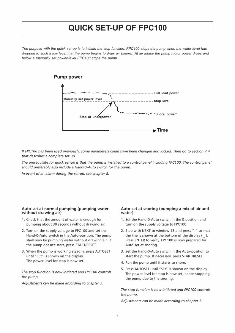
The purpose with the quick set-up is to initiate the stop function. FPC100 stops the pump when the water level hasdropped to such a low level that the pump begins to draw air (snore). At air intake the pump motor power drops andbelow a manually set power-level FPC100 stops the pump.
If FPC100 has been used previously, some parameters could have been changed and locked. Then go to section 7.4
that describes a complete set-up.
The prerequisite for quick set-up is that the pump is installed to a control panel including FPC100. The control panel
should preferably also include a Hand-0-Auto switch for the pump.
In event of an alarm during the set-up, see chapter 8.
Pump power
Manually set power level
Full load power
Stop level
“Snore power”
Time
Stop at underpower
3
0 Quick set-up of FPC100 . . . . . . . . . . . . . . . . . . . . . . . . . . . . . (cover inside)
1 General description . . . . . . . . . . . . . . . . . . . . . . . . . . . . . . . . . . . . . . . . . . 4
2 Safety . . . . . . . . . . . . . . . . . . . . . . . . . . . . . . . . . . . . . . . . . . . . . . . . . . . . . 5
3 Unpacking, inspection and recycling . . . . . . . . . . . . . . . . . . . . . . . . . . . . . 5
4 Installation . . . . . . . . . . . . . . . . . . . . . . . . . . . . . . . . . . . . . . . . . . . . . . . . . 6
1 Connection terminals . . . . . . . . . . . . . . . . . . . . . . . . . . . . . . . . . . . . . . 6
2 Choice and adaptation of current transformer . . . . . . . . . . . . . . . . . . . 7
3 Current transformer connection . . . . . . . . . . . . . . . . . . . . . . . . . . . . . . 8
4 Supply voltage connection . . . . . . . . . . . . . . . . . . . . . . . . . . . . . . . . . . 8
5 Alarm relay connection . . . . . . . . . . . . . . . . . . . . . . . . . . . . . . . . . . . . . 8
6 Pump relay connection . . . . . . . . . . . . . . . . . . . . . . . . . . . . . . . . . . . . . 8
7 Digital input connection . . . . . . . . . . . . . . . . . . . . . . . . . . . . . . . . . . . . 8
8 Terminal 5 connection (e.g. temperature supervision) . . . . . . . . . . . . . 8
5 Front panel layout and function keys . . . . . . . . . . . . . . . . . . . . . . . . . . . . . 9
6 Display, symbols and units . . . . . . . . . . . . . . . . . . . . . . . . . . . . . . . . . . . . . 9
7 Detailed settings . . . . . . . . . . . . . . . . . . . . . . . . . . . . . . . . . . . . . . . . . . . . 10
1 General . . . . . . . . . . . . . . . . . . . . . . . . . . . . . . . . . . . . . . . . . . . . . . 10
2 Lock and unlock menu settings . . . . . . . . . . . . . . . . . . . . . . . . . . . . . . 10
3 Returning to default settings . . . . . . . . . . . . . . . . . . . . . . . . . . . . . . . 10
4 Complete set-up . . . . . . . . . . . . . . . . . . . . . . . . . . . . . . . . . . . . . . . . . 11
5 Adjustment of the stop level . . . . . . . . . . . . . . . . . . . . . . . . . . . . . . . . 12
6 Start conditions and pause time adjustment . . . . . . . . . . . . . . . . . . . 13
7 Window parameters . . . . . . . . . . . . . . . . . . . . . . . . . . . . . . . . . . . . . . 14
8 Protection and alarm . . . . . . . . . . . . . . . . . . . . . . . . . . . . . . . . . . . . . . . . 16
9 Troubleshooting . . . . . . . . . . . . . . . . . . . . . . . . . . . . . . . . . . . . . . . . . . . . 17
10 Technical specifications . . . . . . . . . . . . . . . . . . . . . . . . . . . . . . . . . . . . . . . 18
1 Electronics . . . . . . . . . . . . . . . . . . . . . . . . . . . . . . . . . . . . . . . . . . . . . . 18
2 EU specifications . . . . . . . . . . . . . . . . . . . . . . . . . . . . . . . . . . . . . . . . . 18
3 USA specifications . . . . . . . . . . . . . . . . . . . . . . . . . . . . . . . . . . . . . . . . 19
4 Canadian specifications . . . . . . . . . . . . . . . . . . . . . . . . . . . . . . . . . . . . 19
5 Part numbers . . . . . . . . . . . . . . . . . . . . . . . . . . . . . . . . . . . . . . . . . . . . 19
FPC 100 does not contain separately exchangeable components.
In case of a unit fault the whole unit has to be changed.
Note! Warranty does not cover units with broken seal.
CONTENTS
4
1. GENERAL DESCRIPTION
FPC100 is a pump control unit designed to control and
supervise submersible pumps. Level sensors are not
needed to initiate start and stop. The pump stops
automatically when it begins to snore (draw air).
FPC100 measures the pump times and calculates the
pause times. A long pumping time (large inflow) results
in a short pause time and vice versa. The pause times
are in that way adjusted to the inflow.
As an option a level switch can be used to trigger a
start; either to override the pause time in case of high
level or as the sole means to trigger start.
Independently of chosen starting method, the pump
always stops when it starts to snore (draw air). When
the pump snores, the motor power decreases. FPC100
detects this and stops the pump. FPC100 calculates the
pump motor power from the measured current and
supply voltage. When the power drops below a thresh-
old value initiated with the AUTOSET1-key, FPC100 stops
the pump.
FPC100 is simple to use. One single press of the
AUTOSET-key initiates the unit.
FPC 100 supervision:
• Phase sequence
• Phase voltage asymmetry
• Current from current transformer
• Pump motor temperature and/or appropriate signal
from any voltage-free contact
• Overvoltage and undervoltage check at start up
FPC 100 indication:
• Calculated time to pump start after the latest stop
• Pumping time after the latest start
• Pumping time after the latest start due to high level
• Measured pump motor power in % of the measure-
ment range
• Measured peak power in % of the measurement
range
• Measured supply voltage
• Total pumping time
• Total number of pump starts
• Parameter values
1 Auto-set function is based on technology for which patent by Emotron is pending

5
Antes de empezar cualquier trabajo, comprobar que el armario de sistemas
automáticos esté desconectado de la red eléctrica, y que no pueda recibir tensión.
Prima di iniziare qualsiasi lavoro, controllare che la centralina degli automatismi sia
staccata dalla rete di alimentazione elettrica e che non sia sotto tensione.
Controleer, voordat u begint te werken, of de schakelkast gescheiden is van de
elektrische voeding en niet omder spanning kan komen te staan.
Antes de iniciar qualquer trabalho, verifique se o compartimento do sistema
automático se encontra desligado da rede eléctrica e assegure-se de que a corrente
não poderá ser activada.
Inden nogen form for arbejde påbegyndes, skal det kontrolleres, at automatikskabet
er koblet fra elnettet, og at det ikke kan blive spændingsførende.
Før arbeide påbegynnes, påse at automatikkskapet er frakoplet strømnettet og at det
ikke kan bli spenningsførende.
Ennen kuin mitään työtä aloitetaan, on varmistettava, että automatiikkakaappi on
kytketty irti sähköverkosta eikä voi tulla jännitteiseksi.
Áður en starfræksla hefst, gangið úr skugga um að sjálfvirkur gangsetningarbúnaður
sé óvirkur, þ.e.a.s. ekki tengdur við rafmagn.
Ðñéí áðü êÜèå åñãáóßá, åëÝãîôå áí ôï êéâþôéï ôïõ áõôüìáôïõ åëÝã÷ïõ Ý÷åé áðïóõíäåèåß áðüôï ñåýìá êáé äåí ìðïñåß íá ôåèåß õðü ôÜóç.
2. SAFETY
3. UNPACKING, INSPECTION AND RECYCLING
The delivery comprises:
• FPC100 control unit
• Current transformer
• Installation and user manual for FPC100
If anything is missing or damaged in the delivery,
contact your local ITT Flygt sales office.
Keep the packing. It can be needed for return of the
delivery or in case of inspection at damage.
• Read Technical specifications (chapter 10) before
starting the installation.
• Authorised electrician shall perform the installation.
• The installation shall comply with general and local
regulations.
• Disconnect all supply circuits before installation. Also
disconnect all supply circuits before connecting and
disconnecting cables to FPC100.
FPC 100 conforms to international standards and is UL/
CSA and CE-marked.
The housing of the FPC100 is made of recyclable plastic,
type PC/ABS. The circuit boards contain minimal
amounts of tin and lead.
When scrapping the FPC100, all parts must be handled
and recycled according to local regulations.
Before doing any work, check
that the automatic control
cubicle is disconnected from
the power supply and cannot
become live.
Always isolate the power supply
before attempting to trace a
fault. Otherwise the pump can
start without warning.
Flygt sales office.
6
PE
L1
L2
L3
N
M
3
Max240VAC
Hand
I Digin
Temp Alarm Pump1 3 4 5 7 86
9
L1
11
L2 L3
13
2
Supply
Auto 0
Alarm
Auto-set
Reset
High level
Thermistor (PTC)or
Thermal contact
Alternative connection
KFPC100
R
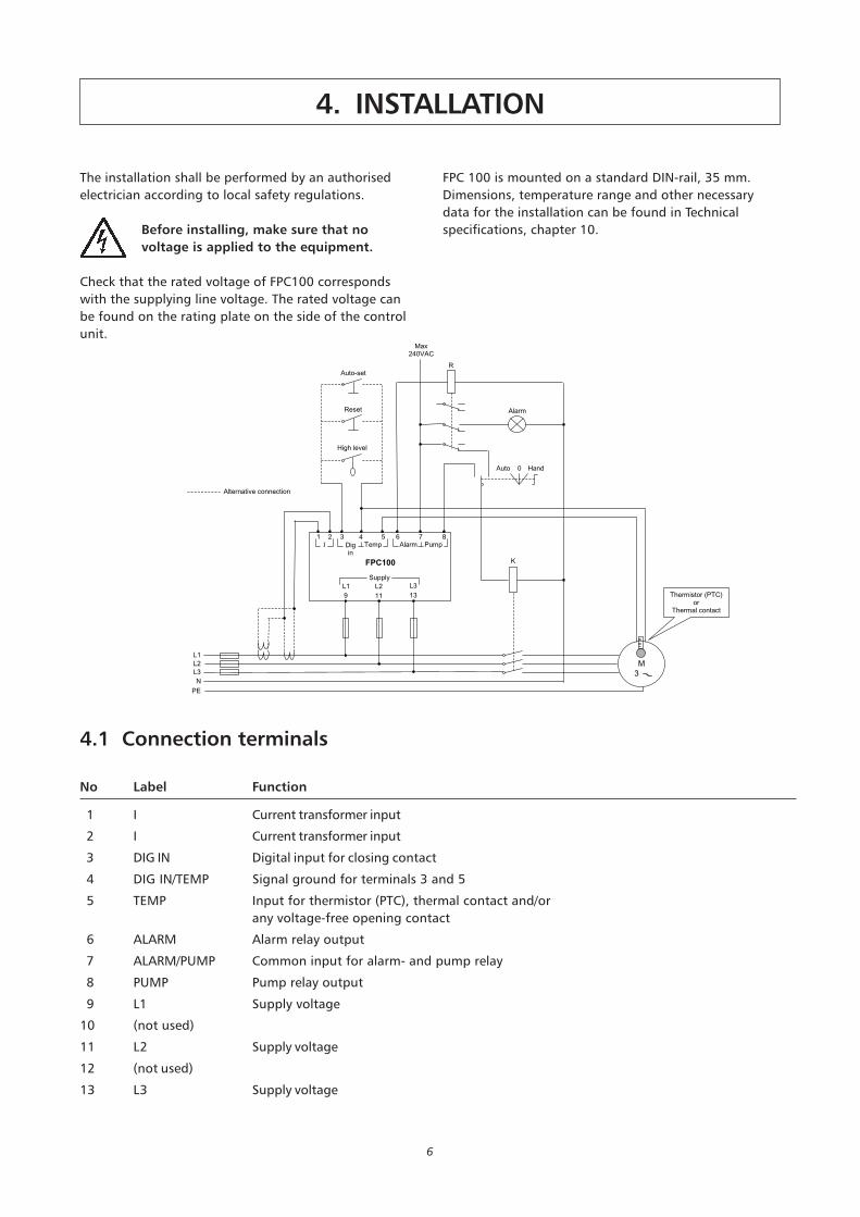
The installation shall be performed by an authorised
electrician according to local safety regulations.
Before installing, make sure that no
voltage is applied to the equipment.
Check that the rated voltage of FPC100 corresponds
with the supplying line voltage. The rated voltage can
be found on the rating plate on the side of the control
unit.
4.1 Connection terminals
No Label Function
1 I Current transformer input
2 I Current transformer input
3 DIG IN Digital input for closing contact
4 DIG IN/TEMP Signal ground for terminals 3 and 5
5 TEMP Input for thermistor (PTC), thermal contact and/or
any voltage-free opening contact
6 ALARM Alarm relay output
7 ALARM/PUMP Common input for alarm- and pump relay
8 PUMP Pump relay output
9 L1 Supply voltage
10 (not used)
11 L2 Supply voltage
12 (not used)
13 L3 Supply voltage
FPC 100 is mounted on a standard DIN-rail, 35 mm.
Dimensions, temperature range and other necessary
data for the installation can be found in Technical
specifications, chapter 10.
4. INSTALLATION
7
4.2 Choice and adaptation of current transformer
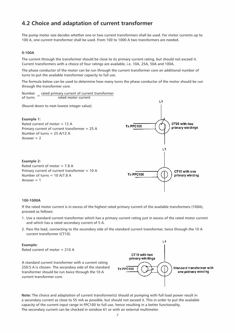
Note: The choice and adaptation of current transformer(s) should at pumping with full load power result in
a secondary current as close to 55 mA as possible, but should not exceed it. This in order to put the available
capacity of the current input range in FPC100 to full use, hence resulting in a better functionality.
The secondary current can be checked in window 61 or with an external multimeter.
100-1000A
If the rated motor current is in excess of the highest rated primary current of the available transformers (100A),
proceed as follows:
1. Use a standard current transformer which has a primary current rating just in excess of the rated motor current
and which has a rated secondary current of 5 A.
2. Pass the lead, connecting to the secondary side of the standard current transformer, twice through the 10 A
current transformer (CT10).
The pump motor size decides whether one or two current transformers shall be used. For motor currents up to
100 A, one current transformer shall be used. From 100 to 1000 A two transformers are needed.
0-100A
The current through the transformer should be close to its primary current rating, but should not exceed it.
Current transformers with a choice of four ratings are available, i.e. 10A, 25A, 50A and 100A.
The phase conductor of the motor can be run through the current transformer core an additional number of
turns to put the available transformer capacity to full use.
The formula below can be used to determine how many turns the phase conductor of the motor should be run
through the transformer core.
Number =
rated primary current of current transformerof turns rated motor current
(Round down to next lowest integer value).
Example 2:
Rated current of motor = 7.8 A
Primary current of current transformer = 10 A
Number of turns = 10 A/7.8 A
Answer = 1
Example 1:
Rated current of motor = 12 A
Primary current of current transformer = 25 A
Number of turns = 25 A/12 A
Answer = 2
Example:
Rated current of motor = 210 A
A standard current transformer with a current rating
250:5 A is chosen. The secondary side of the standard
transformer should be run twice through the 10 A
current transformer core.
8
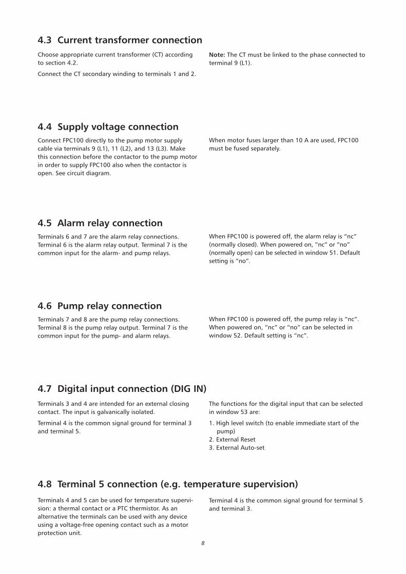
4.4 Supply voltage connection
Connect FPC100 directly to the pump motor supply
cable via terminals 9 (L1), 11 (L2), and 13 (L3). Make
this connection before the contactor to the pump motor
in order to supply FPC100 also when the contactor is
open. See circuit diagram.
4.5 Alarm relay connection
Terminals 6 and 7 are the alarm relay connections.
Terminal 6 is the alarm relay output. Terminal 7 is the
common input for the alarm- and pump relays.
4.6 Pump relay connection
Terminals 7 and 8 are the pump relay connections.
Terminal 8 is the pump relay output. Terminal 7 is the
common input for the pump- and alarm relays.
Note: The CT must be linked to the phase connected to
terminal 9 (L1).
When motor fuses larger than 10 A are used, FPC100
must be fused separately.
When FPC100 is powered off, the alarm relay is “nc”
(normally closed). When powered on, “nc” or “no”
(normally open) can be selected in window 51. Default
setting is “no”.
When FPC100 is powered off, the pump relay is “nc”.
When powered on, “nc” or “no” can be selected in
window 52. Default setting is “nc”.
Choose appropriate current transformer (CT) according
to section 4.2.
Connect the CT secondary winding to terminals 1 and 2.
4.3 Current transformer connection
4.8 Terminal 5 connection (e.g. temperature supervision)
Terminals 4 and 5 can be used for temperature supervi-
sion: a thermal contact or a PTC thermistor. As an
alternative the terminals can be used with any device
using a voltage-free opening contact such as a motor
protection unit.
The functions for the digital input that can be selected
in window 53 are:
1. High level switch (to enable immediate start of the
pump)
2. External Reset
3. External Auto-set
4.7 Digital input connection (DIG IN)
Terminals 3 and 4 are intended for an external closing
contact. The input is galvanically isolated.
Terminal 4 is the common signal ground for terminal 3
and terminal 5.
Terminal 4 is the common signal ground for terminal 5
and terminal 3.
9
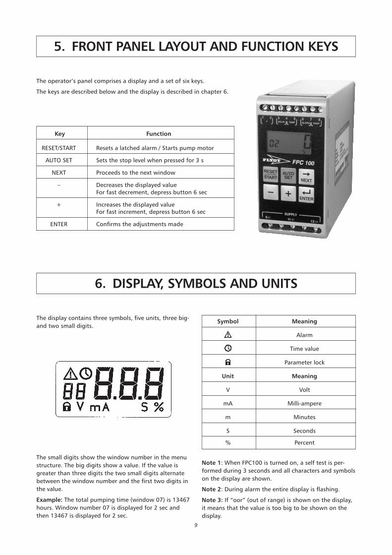
5. FRONT PANEL LAYOUT AND FUNCTION KEYS
The operator’s panel comprises a display and a set of six keys.
The keys are described below and the display is described in chapter 6.
Key Function
RESET/START Resets a latched alarm / Starts pump motor
AUTO SET Sets the stop level when pressed for 3 s
NEXT Proceeds to the next window
– Decreases the displayed valueFor fast decrement, depress button 6 sec
+ Increases the displayed valueFor fast increment, depress button 6 sec
ENTER Confirms the adjustments made
6. DISPLAY, SYMBOLS AND UNITS
The display contains three symbols, five units, three big-
and two small digits.
The small digits show the window number in the menu
structure. The big digits show a value. If the value is
greater than three digits the two small digits alternate
between the window number and the first two digits in
the value.
Example: The total pumping time (window 07) is 13467
hours. Window number 07 is displayed for 2 sec and
then 13467 is displayed for 2 sec.
Note 1: When FPC100 is turned on, a self test is per-
formed during 3 seconds and all characters and symbols
on the display are shown.
Note 2: During alarm the entire display is flashing.
Note 3: If “oor” (out of range) is shown on the display,
it means that the value is too big to be shown on the
display.
Symbol Meaning
Alarm
Time value
Parameter lock
Unit Meaning
V Volt
mA Milli-ampere
m Minutes
S Seconds
% Percent

10
7.1 General
Adjustments and settings are done in a single-level menu structure, windows 00-99.
When FPC100 is turned on, press NEXT to proceed to the next window, press + or – to increase
or decrease the value and press ENTER to confirm the new value in each window.
One minute after any key has been pressed, FPC100 returns to:
• window 00 if there is an alarm
• window 01 if the pump is pausing
• window 02 if the pump is pumping
• window 03 if the pump is pumping due to start on high level switch
See section 7.7 for a summary of all the menu windows.
7. DETAILED SETTINGS
7.3 Returning to default settings
If any value differs from the default settings, “Usr” (set
by the user) is displayed in window 99. Press + to return
to the default settings. “dEF” (default setting) is then
shown in the window. Confirm by pressing ENTER. All
It is possible to avoid unintentional change of para-
meters. Set window 09 to 369 and confirm with ENTER.
A padlock is shown, indicating access only to windows
00-09. Re-entering value 369 and confirming with
ENTER gives access to all windows.
7.2 Lock and unlock menu settings
user settings are erased and replaced by default settings
according to section 7.7. New user settings must be re-
entered.
11
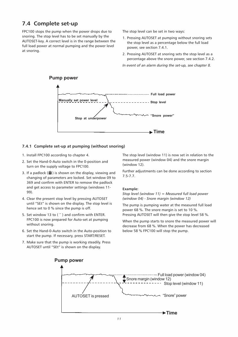
7.4 Complete set-up
FPC100 stops the pump when the power drops due to
snoring. The stop level has to be set manually by the
AUTOSET-key. A correct level is in the range between the
full load power at normal pumping and the power level
at snoring.
1. Install FPC100 according to chapter 4.
2. Set the Hand-0-Auto switch in the 0-position and
turn on the supply voltage to FPC100.
3. If a padlock ( ) is shown on the display, viewing and
changing of parameters are locked. Set window 09 to
369 and confirm with ENTER to remove the padlock
and get access to parameter settings (windows 11-
99).
4. Clear the present stop level by pressing AUTOSET
until “SEt” is shown on the display. The stop level is
hence set to 0 % since the pump is off.
5. Set window 13 to ( – ) and confirm with ENTER.
FPC100 is now prepared for Auto-set at pumping
without snoring.
6. Set the Hand-0-Auto switch in the Auto-position to
start the pump. If necessary, press START/RESET.
7. Make sure that the pump is working steadily. Press
AUTOSET until “SEt” is shown on the display.
7.4.1 Complete set-up at pumping (without snoring)
The stop level can be set in two ways:
1. Pressing AUTOSET at pumping without snoring sets
the stop level as a percentage below the full load
power, see section 7.4.1.
2. Pressing AUTOSET at snoring sets the stop level as a
percentage above the snore power, see section 7.4.2.
In event of an alarm during the set-up, see chapter 8.
The stop level (window 11) is now set in relation to the
measured power (window 04) and the snore margin
(window 12).
Further adjustments can be done according to section
7.5-7.7.
Example:
Stop level (window 11) = Measured full load power
(window 04) - Snore margin (window 12)
The pump is pumping water at the measured full load
power 68 %. The snore margin is set to 10 %.
Pressing AUTOSET will then give the stop level 58 %.
When the pump starts to snore the measured power will
decrease from 68 %. When the power has decreased
below 58 % FPC100 will stop the pump.
Pump power
Manually set power level
Full load power
Stop level
“Snore power”
Time
Stop at underpower
Pump power
Full load power (window 04)Snore margin (window 12)
“Snore” power
Stop level (window 11)
AUTOSET is pressed
Time
12
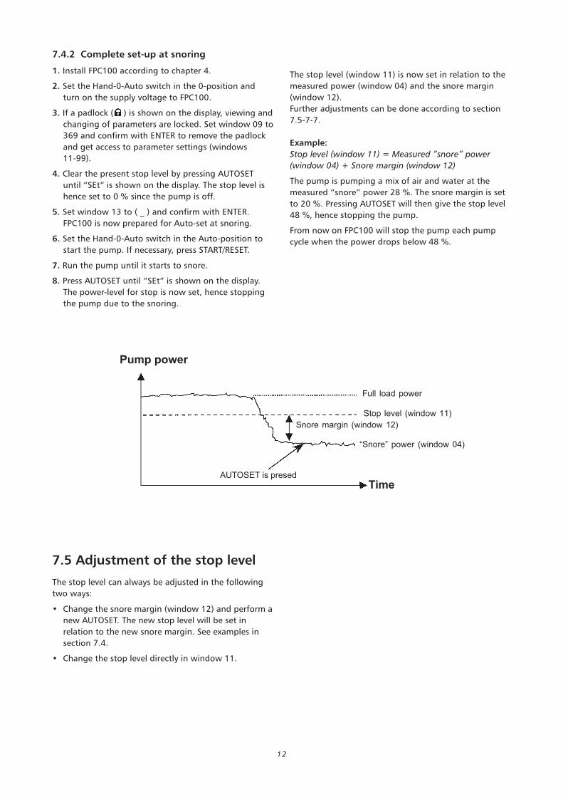
7.4.2 Complete set-up at snoring
1. Install FPC100 according to chapter 4.
2. Set the Hand-0-Auto switch in the 0-position and
turn on the supply voltage to FPC100.
3. If a padlock ( ) is shown on the display, viewing and
changing of parameters are locked. Set window 09 to
369 and confirm with ENTER to remove the padlock
and get access to parameter settings (windows
11-99).
4. Clear the present stop level by pressing AUTOSET
until “SEt” is shown on the display. The stop level is
hence set to 0 % since the pump is off.
5. Set window 13 to ( _ ) and confirm with ENTER.
FPC100 is now prepared for Auto-set at snoring.
6. Set the Hand-0-Auto switch in the Auto-position to
start the pump. If necessary, press START/RESET.
7. Run the pump until it starts to snore.
8. Press AUTOSET until “SEt” is shown on the display.
The power-level for stop is now set, hence stopping
the pump due to the snoring.
The stop level (window 11) is now set in relation to the
measured power (window 04) and the snore margin
(window 12).
Further adjustments can be done according to section
7.5-7-7.
Example:
Stop level (window 11) = Measured “snore” power
(window 04) + Snore margin (window 12)
The pump is pumping a mix of air and water at the
measured “snore” power 28 %. The snore margin is set
to 20 %. Pressing AUTOSET will then give the stop level
48 %, hence stopping the pump.
From now on FPC100 will stop the pump each pump
cycle when the power drops below 48 %.
The stop level can always be adjusted in the following
two ways:
• Change the snore margin (window 12) and perform a
new AUTOSET. The new stop level will be set in
relation to the new snore margin. See examples in
section 7.4.
• Change the stop level directly in window 11.
7.5 Adjustment of the stop level
Pump power
Full load power
AUTOSET is presedTime
Snore margin (window 12)
“Snore” power (window 04)
Stop level (window 11)
13
In normal operation there are three starting options:
1. Pump start after calculated pause time (window
25 = “on”)
2. Pump start after calculated pause time, or at high
level (window 25 = “on”, window 53 = “1”)
3. Pump start at high level only (window 25 = “OFF”,
window 53 = “1”)
Note: Option 2 and 3 require connection of a high level
switch according to section 4.7.
The pump will also start if a non-latched alarm disap-
pears or if the START-button is pressed during pause.
Calculation of pause time is based on previous pump-
ing- and pause times and is controlled by the two
parameters level setting (window 21) and maximum
pause time (window 22). The parameters can be
adjusted to achieve the desired sizes of pause times,
start level and number of starts per hour.
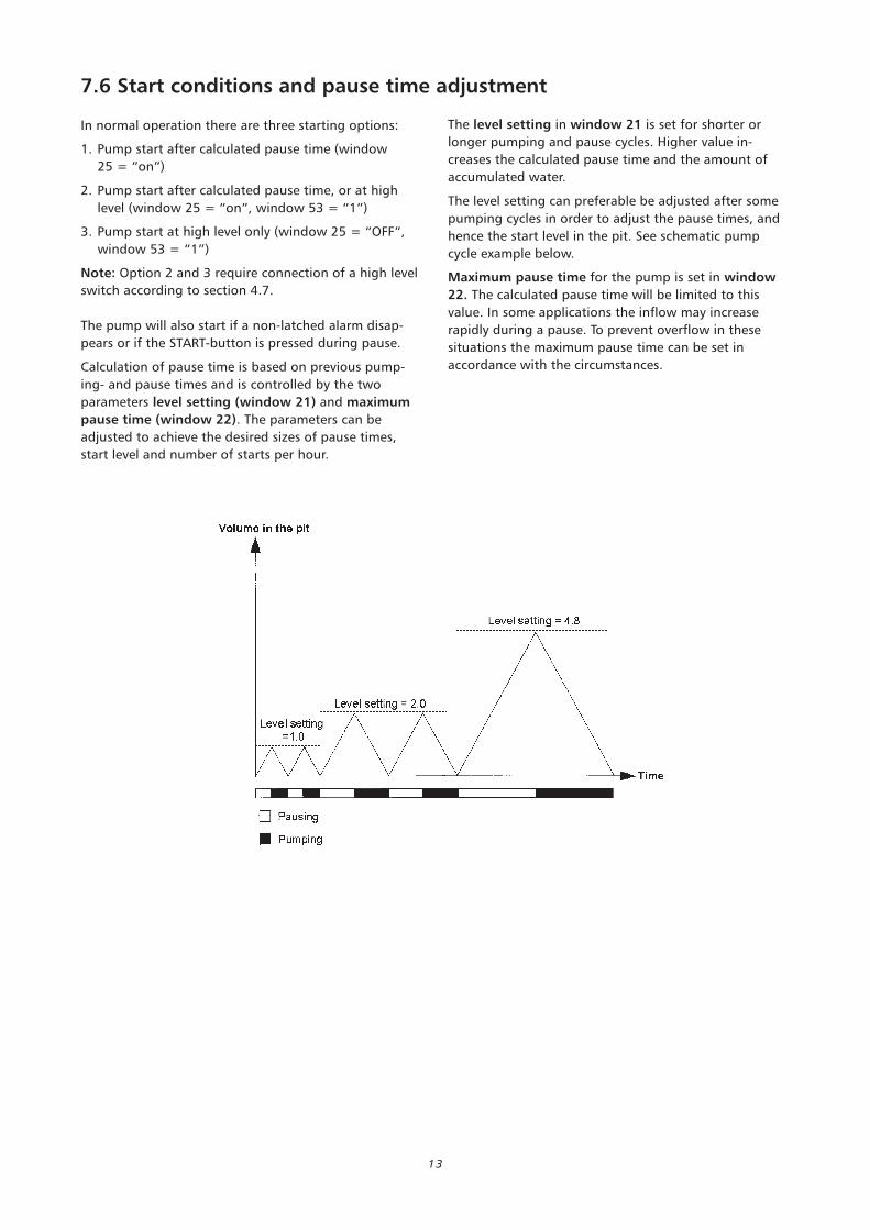
7.6 Start conditions and pause time adjustment
The level setting in window 21 is set for shorter or
longer pumping and pause cycles. Higher value in-
creases the calculated pause time and the amount of
accumulated water.
The level setting can preferable be adjusted after some
pumping cycles in order to adjust the pause times, and
hence the start level in the pit. See schematic pump
cycle example below.
Maximum pause time for the pump is set in window
22. The calculated pause time will be limited to this
value. In some applications the inflow may increase
rapidly during a pause. To prevent overflow in these
situations the maximum pause time can be set in
accordance with the circumstances.
14
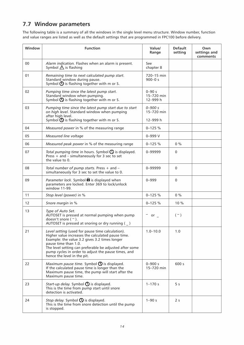
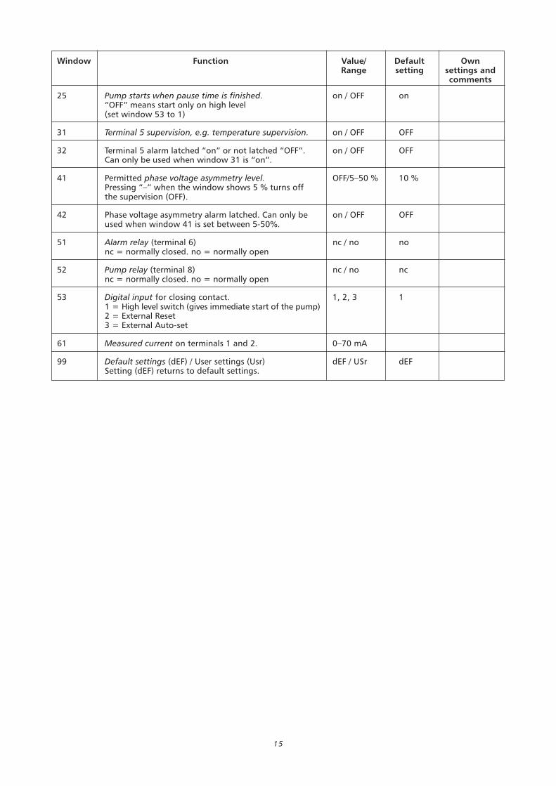
7.7 Window parameters
The following table is a summary of all the windows in the single level menu structure. Window number, function
and value ranges are listed as well as the default settings that are programmed in FPC100 before delivery.
Window Function Value/ Default OwnRange setting settings and
comments
00 Alarm indication. Flashes when an alarm is present. SeeSymbol is flashing chapter 8
01 Remaining time to next calculated pump start. 720–15 minStandard window during pause. 900–0 sSymbol is flashing together with m or S.
02 Pumping time since the latest pump start. 0–90 sStandard window when pumping. 15–720 minSymbol is flashing together with m or S. 12–999 h
03 Pumping time since the latest pump start due to start 0–900 son high level. Standard window when pumping 15–720 minafter high level.Symbol is flashing together with m or S. 12–999 h
04 Measured power in % of the measuring range 0–125 %
05 Measured line voltage 0–999 V
06 Measured peak power in % of the measuring range 0–125 % 0 %
07 Total pumping time in hours. Symbol is displayed. 0–99999 0Press + and – simultaneously for 3 sec to setthe value to 0.
08 Total number of pump starts. Press + and – 0–99999 0simultaneously for 3 sec to set the value to 0.
09 Parameter lock. Symbol is displayed when 0–999 0parameters are locked. Enter 369 to lock/unlockwindow 11-99.
11 Stop level (power) in % 0–125 % 0 %
12 Snore margin in % 0–125 % 10 %
13 Type of Auto Set.AUTOSET is pressed at normal pumping when pump
_ or _ (
_ )
doesn’t snore ( _
).AUTOSET is pressed at snoring or dry running ( _ )
21 Level setting (used for pause time calculation). 1.0–10.0 1.0Higher value increases the calculated pause time.Example: the value 3.2 gives 3.2 times longerpause time than 1.0.The level setting can preferable be adjusted after somepump cycles in order to adjust the pause times, andhence the level in the pit.
22 Maximum pause time. Symbol is displayed. 0–900 s 600 sIf the calculated pause time is longer than the 15–720 minMaximum pause time, the pump will start after theMaximum pause time.
23 Start-up delay. Symbol is displayed. 1–170 s 5 sThis is the time from pump start until snoredetection is activated.
24 Stop delay. Symbol is displayed. 1–90 s 2 sThis is the time from snore detection until the pumpis stopped.
15
Window Function Value/ Default OwnRange setting settings and
comments
25 Pump starts when pause time is finished. on / OFF on“OFF” means start only on high level(set window 53 to 1)
31 Terminal 5 supervision, e.g. temperature supervision. on / OFF OFF
32 Terminal 5 alarm latched “on” or not latched “OFF”. on / OFF OFFCan only be used when window 31 is “on”.
41 Permitted phase voltage asymmetry level. OFF/5–50 % 10 %Pressing “–” when the window shows 5 % turns offthe supervision (OFF).
42 Phase voltage asymmetry alarm latched. Can only be on / OFF OFFused when window 41 is set between 5-50%.
51 Alarm relay (terminal 6) nc / no nonc = normally closed. no = normally open
52 Pump relay (terminal 8) nc / no ncnc = normally closed. no = normally open
53 Digital input for closing contact. 1, 2, 3 11 = High level switch (gives immediate start of the pump)2 = External Reset3 = External Auto-set
61 Measured current on terminals 1 and 2. 0–70 mA
99 Default settings (dEF) / User settings (Usr) dEF / USr dEFSetting (dEF) returns to default settings.
16
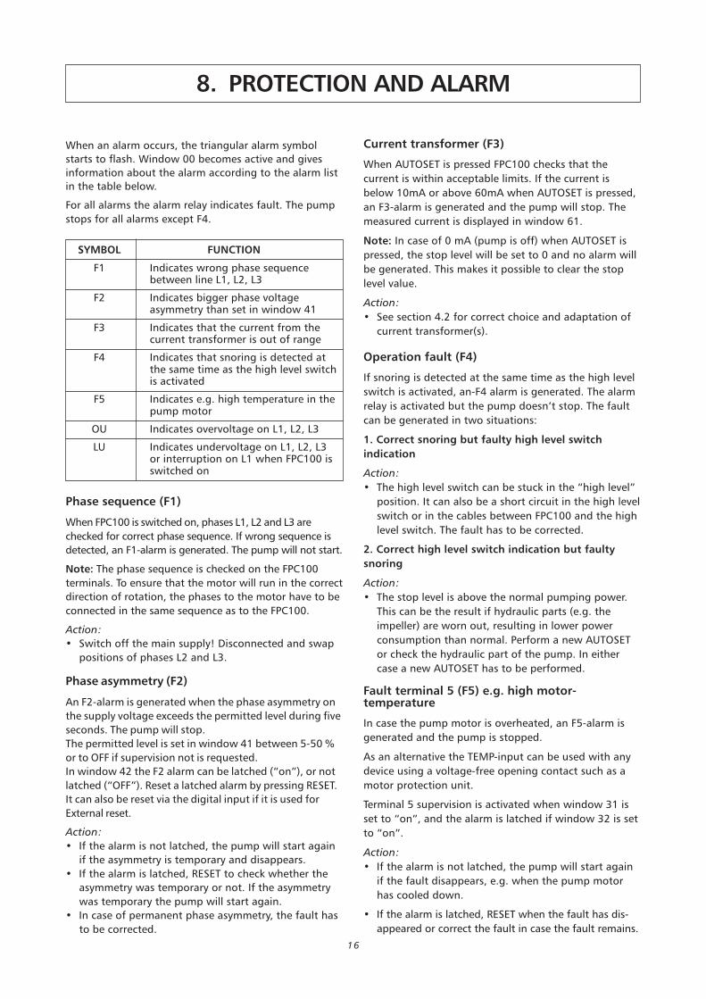
When an alarm occurs, the triangular alarm symbol
starts to flash. Window 00 becomes active and gives
information about the alarm according to the alarm list
in the table below.
For all alarms the alarm relay indicates fault. The pump
stops for all alarms except F4.
8. PROTECTION AND ALARM
Phase sequence (F1)
When FPC100 is switched on, phases L1, L2 and L3 are
checked for correct phase sequence. If wrong sequence is
detected, an F1-alarm is generated. The pump will not start.
Note: The phase sequence is checked on the FPC100
terminals. To ensure that the motor will run in the correct
direction of rotation, the phases to the motor have to be
connected in the same sequence as to the FPC100.
Action:
• Switch off the main supply! Disconnected and swap
positions of phases L2 and L3.
Phase asymmetry (F2)
An F2-alarm is generated when the phase asymmetry on
the supply voltage exceeds the permitted level during five
seconds. The pump will stop.
The permitted level is set in window 41 between 5-50 %
or to OFF if supervision not is requested.
In window 42 the F2 alarm can be latched (“on”), or not
latched (“OFF”). Reset a latched alarm by pressing RESET.
It can also be reset via the digital input if it is used for
External reset.
Action:
• If the alarm is not latched, the pump will start again
if the asymmetry is temporary and disappears.
• If the alarm is latched, RESET to check whether the
asymmetry was temporary or not. If the asymmetry
was temporary the pump will start again.
• In case of permanent phase asymmetry, the fault has
to be corrected.
SYMBOL FUNCTION
F1 Indicates wrong phase sequencebetween line L1, L2, L3
F2 Indicates bigger phase voltageasymmetry than set in window 41
F3 Indicates that the current from thecurrent transformer is out of range
F4 Indicates that snoring is detected atthe same time as the high level switchis activated
F5 Indicates e.g. high temperature in thepump motor
OU Indicates overvoltage on L1, L2, L3
LU Indicates undervoltage on L1, L2, L3or interruption on L1 when FPC100 isswitched on
Current transformer (F3)
When AUTOSET is pressed FPC100 checks that the
current is within acceptable limits. If the current is
below 10mA or above 60mA when AUTOSET is pressed,
an F3-alarm is generated and the pump will stop. The
measured current is displayed in window 61.
Note: In case of 0 mA (pump is off) when AUTOSET is
pressed, the stop level will be set to 0 and no alarm will
be generated. This makes it possible to clear the stop
level value.
Action:
• See section 4.2 for correct choice and adaptation of
current transformer(s).
Operation fault (F4)
If snoring is detected at the same time as the high level
switch is activated, an-F4 alarm is generated. The alarm
relay is activated but the pump doesn’t stop. The fault
can be generated in two situations:
1. Correct snoring but faulty high level switch
indication
Action:
• The high level switch can be stuck in the “high level”
position. It can also be a short circuit in the high level
switch or in the cables between FPC100 and the high
level switch. The fault has to be corrected.
2. Correct high level switch indication but faulty
snoring
Action:
• The stop level is above the normal pumping power.
This can be the result if hydraulic parts (e.g. the
impeller) are worn out, resulting in lower power
consumption than normal. Perform a new AUTOSET
or check the hydraulic part of the pump. In either
case a new AUTOSET has to be performed.
Fault terminal 5 (F5) e.g. high motor-temperature
In case the pump motor is overheated, an F5-alarm is
generated and the pump is stopped.
As an alternative the TEMP-input can be used with any
device using a voltage-free opening contact such as a
motor protection unit.
Terminal 5 supervision is activated when window 31 is
set to “on”, and the alarm is latched if window 32 is set
to “on”.
Action:
• If the alarm is not latched, the pump will start again
if the fault disappears, e.g. when the pump motor
has cooled down.
• If the alarm is latched, RESET when the fault has dis-
appeared or correct the fault in case the fault remains.

17
Under/Overvoltage (LU/OU)
When FPC 100 is switched on, the voltages on phases
L1, L2 and L3 are checked. If a wrong phase voltage is
detected, LU (undervoltage) or OU (overvoltage) alarm is
generated. The pump will not start.
Under/overvoltage is detected if the phase voltage is
outside the voltage range including tolerance (e.g.
3×380-500VAC +/–10%).
Note: Under/overvoltage supervision is only activated at
start up when FPC100 is switched on. The purpose with
the supervision is to ensure that correct FPC100 (correct
voltage range) is used.
9. TROUBLESHOOTING
Window 00 shows F1-F5, LU or OU
Fault handling according to chapter 8.
Impossible to do Auto-set
Auto-set is disconnected during the Start-up delay
period or if an alarm indication is present.
The pump starts and stops too often or seldom,or the level in the pit is too low or too high
Change the settings in window 21 and window 22
according to section 7.6.
The pump stops although it is not snoring
Check the stop level value in window 11. This value is
probably too high in relation to measured power in
window 04. The pump operating power may have
decreased due to worn out hydraulic parts. Perform
a new AUTOSET according to chapter 7 or change
hydraulic parts if necessary. If hydraulic parts are
changed, a new AUTOSET has to be performed.
The pump doesn’t stop when snoring
Check the stop level value in window 11. This value is
probably too low in relation to measured power in
window 04. Perform a new AUTOSET according to
chapter 7.
The value in window 04 increases when thepump starts to snore
Check that the current transformer(s) is linked to the
phase connected to terminal 9 (L1).
“oor” (out of range) is shown on the display
This means that the value is too big to be shown on the
display. The values in windows 06, 07 and 08 can be set
to 0 by pressing – and + simultaneously for three
seconds.
FPC100 unit is damaged or “dead“
• Component failure in FPC100. FPC100 has to be
changed.
• Power supply to FPC100 (L2 or/and L3) is interrupted.
Check wiring.
If L1 is interrupted when FPC100 is switched on, LU
(undervoltage) alarm is generated.
Action:
Check that the rated voltage of FPC100 corresponds
with the supplying line voltage. The rated voltage can
be found on the rating plate on the side of the control
unit.
Check that L1 is not interrupted.
18
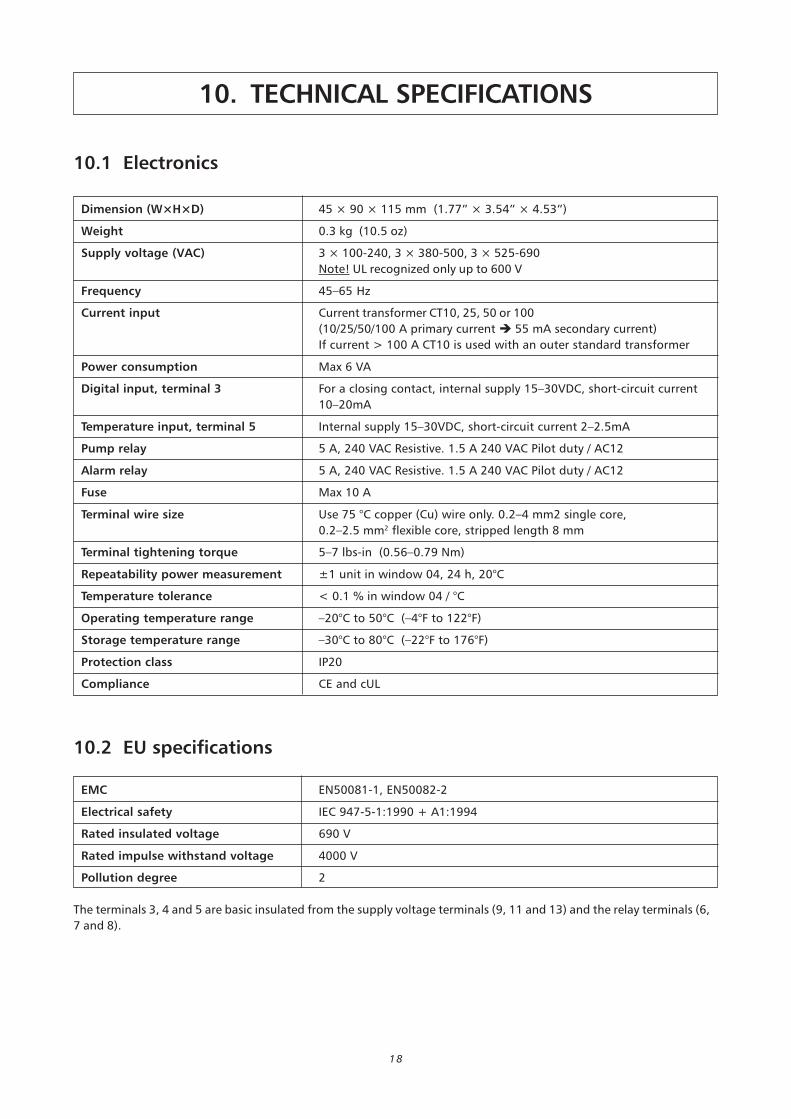
10.1 Electronics
Dimension (W×H×D) 45 × 90 × 115 mm (1.77” × 3.54” × 4.53”)
Weight 0.3 kg (10.5 oz)
Supply voltage (VAC) 3 × 100-240, 3 × 380-500, 3 × 525-690
Note! UL recognized only up to 600 V
Frequency 45–65 Hz
Current input Current transformer CT10, 25, 50 or 100
(10/25/50/100 A primary current 55 mA secondary current)
If current > 100 A CT10 is used with an outer standard transformer
Power consumption Max 6 VA
Digital input, terminal 3 For a closing contact, internal supply 15–30VDC, short-circuit current
10–20mA
Temperature input, terminal 5 Internal supply 15–30VDC, short-circuit current 2–2.5mA
Pump relay 5 A, 240 VAC Resistive. 1.5 A 240 VAC Pilot duty / AC12
Alarm relay 5 A, 240 VAC Resistive. 1.5 A 240 VAC Pilot duty / AC12
Fuse Max 10 A
Terminal wire size Use 75 °C copper (Cu) wire only. 0.2–4 mm2 single core,
0.2–2.5 mm2 flexible core, stripped length 8 mm
Terminal tightening torque 5–7 lbs-in (0.56–0.79 Nm)
Repeatability power measurement ±1 unit in window 04, 24 h, 20°C
Temperature tolerance < 0.1 % in window 04 / °C
Operating temperature range –20°C to 50°C (–4°F to 122°F)
Storage temperature range –30°C to 80°C (–22°F to 176°F)
Protection class IP20
Compliance CE and cUL
10.2 EU specifications
EMC EN50081-1, EN50082-2
Electrical safety IEC 947-5-1:1990 + A1:1994
Rated insulated voltage 690 V
Rated impulse withstand voltage 4000 V
Pollution degree 2
The terminals 3, 4 and 5 are basic insulated from the supply voltage terminals (9, 11 and 13) and the relay terminals (6,
7 and 8).
10. TECHNICAL SPECIFICATIONS
19
10.3 USA specifications
FCC (Federal Communications Commission)
FPC100 has been tested and found to comply with the
limits for a class A digital device pursuant to Part 15 of
the FCC Rules. These limits are designed to provide
reasonable protection against harmful interference
when the equipment is operated in a commercial
environment. FPC100 generates, uses and can radiate
radio frequency energy and, if not installed and used in
accordance with this manual, may cause harmful
interference, in which case, the user will be required to
correct the interference at their own expense.
10.4 Canadian specifications
DOC (Department of Communications)
FPC100 does not exceed the Class A limits for radio
noise emissions from digital apparatus as set out in the
Canadian interference-Causing Equipment Regulations.
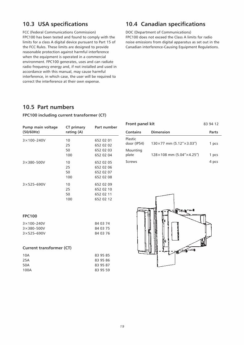
10.5 Part numbers
FPC100 including current transformer (CT)
Pump main voltage CT primary Part number
(50/60Hz) rating (A)
3×100–240V 10 652 02 01
25 652 02 02
50 652 02 03
100 652 02 04
3×380–500V 10 652 02 05
25 652 02 06
50 652 02 07
100 652 02 08
3×525–690V 10 652 02 09
25 652 02 10
50 652 02 11
100 652 02 12
FPC100
3×100–240V 84 03 74
3×380–500V 84 03 75
3×525–690V 84 03 76
Current transformer (CT)
10A 83 95 85
25A 83 95 86
50A 83 95 87
100A 83 95 59
Front panel kit 83 94 12
Contains Dimension Parts
Plasticdoor (IP54) 130×77 mm (5.12″×3.03″) 1 pcs
Mountingplate 128×108 mm (5.04″×4.25″) 1 pcs
Screws 4 pcs

www.flygt.com 893739_0
4_E
N_G
B_I
NST_F
PC
100.p
df
© I
TT F
LYG
T A
B T
his
sp
eci
fica
tio
n m
ay
chan
ge w
ith
ou
t fu
rth
er
no
tice
.
www.flygt.com 893739_0
4_E
N_G
B_I
NST_F
PC
100.p
df
© I
TT F
LYG
T A
B T
his
sp
eci
fica
tio
n m
ay
chan
ge w
ith
ou
t fu
rth
er
no
tice
.