Embed Size (px)
Citation preview

Single Turbo RX-7s and the Power FC
Brian Davies“Wargasm” on www.rx7club.com
Version 0.6 (First Revision)12/15/04
Warning and Disclaimer: I am not an expert in building or tuning cars. I am not a certified mechanic. I amonly trying to share my experience with others to help them on their own path to learning. Working onyour own car entails significant risk of loss or damage; by using this information, you are agreeing toaccept all risks.
In addition, any performance testing of automobiles on public roads is very dangerous, and isillegal. Please obey all laws when working with your car and do not endanger yourself or others. Where Iuse the term “road” or “street” in this document, I am referring to a closed-off area such as a racetrackbuilt for the purpose of testing or racing vehicles. I am not suggesting that anyone drive in an unsafemanner on public roadways.
Abstract: This document is meant to explain some of the basic concepts and methods used to tune a single turbo1993+ Mazda RX-7 using the Apexi Power FC in combination with the Datalogit interface box, a laptop computer,and a wideband oxygen sensor.
This document is created with the unregistered version of Document2PDF Pilot.

Table of Contents
1 – Introduction – Why we need an EMS like the Power FC
2 – Setup – Putting together your car and getting the Datalogit, Power FC, and Wideband all speaking toeach other
3 – Power FC Settings – What do all the settings mean?
4 – Using FC-Edit – How to use some of the best features in FC-Edit for tuning
5 – Tuning – Going out and getting some tuning done
6 – References – A brief list of websites to check for information
This document is created with the unregistered version of Document2PDF Pilot.
1. Introduction: Many car enthusiasts who modify a 1993 or newer RX-7 eventually replace the factory twinturbo setup with a larger single turbo setup. This is done for many reasons, the main one being the quest for morepower of course!
After just a few of the basic bolt-on modifications are done, in order to get more power safely, it is necessaryto adjust the amount of fuel being put into the engine in relation to airflow into the engine. You may ask yourself,“With all these computer controls, how can it be that the car doesn’t ‘know’ that we’ve performed somemodifications and automatically adjust things like the fuel injection amount?” Some cars such as the 86-91 RX-7 canmake some adjustments on their own to compensate for more airflow with more fuel. This is because that car has amechanical air flow meter with a flapper trap door that swings open as more air comes into the engine. By measuringhow much the flapper is being sucked open, the car knows that a certain amount of air has come into the engine andcan make some adjustments (within reason).
Our 1993+ RX-7 does NOT have this type of system. A trap door flapper is basically a restriction in theairflow path so it does hurt performance a bit. There are probably other bad things about mechanical air flow meters,but I don’t know what they are. Instead of using the mechanical air flow meter, our cars use what is called a speeddensity system. In this system, the car measures the RPM, the air temperature, the manifold pressure, and uses apre-defined (by Mazda) value for the volumetric efficiency of the engine under those conditions. It may also measureother things such as the atmospheric pressure, water temp, etc. The theory here is that if you know everything there isto know about the engine, you know the temperature of the air, you know the pressure of the air, you know the RPMof the engine… you can just CALCULATE what the airflow must be. This works great for a car that is completelystock. Since all the cars come off the same assembly line, they are all pretty much the same and they will all suck inthe same amount of air if RPM, temp, etc is all the same from car to car. So, once our friends at Mazda figure outhow much air the prototype RX-7 sucks in for every combination of factors, they just apply that to ALL of them. You can see that if we open up the exhaust, put on a low restriction intake, and add a catback exhaust, we havesignificantly changed the volumetric efficiency of the engine. It is now flowing more air at the same RPM, boost, etcbut the ECU has no idea. It just dumbly injects the same old amount of fuel as it would have the day it left Hiroshimaand thinks everything is OK.
You can see that this system is not going to let you make a lot of changes without causing damage. Ideally, inaddition to altering the amount of fuel injected we would also change other parameters such as ignition timing. Wecan make some of our changes in one of three ways.
The easiest way is to have your factory ECU opened up and have a new chip put in that contains differentprogramming information. This will tell the computer how to handle more airflow by putting in more fuel. All the carowner has to do is send out the ECU to a vendor such as Pettit Racing, M2 Performance, or another shop and theywill send it back reprogrammed. They can modify your fuel injection amount and your ignition timing (and possiblyother things?). The user just plugs it in and is done. The problem with this method is that it is NOT completelycustomized for your specific car (no matter what they tell you). At best, it is a conservative “ballpark” setup whichwill let you get some more power safely, but sacrifice some power to get that reliability. At worst, it is not safeenough and you will damage your engine. At the time of this writing, this costs somewhere around 800 dollars US. Itis possible to remove it and reprogram again and again in most cases if you want to change your setup. Each time,they will charge a fee! This method can work well on an RX-7 with a few modifications such as an intake, downpipe,and a catback exhaust, especially if you are the type of person that just wants some basic power increase and doesn’twant to fool with things yourself. If you are going to run a single turbo or you want to run a midpipe (no cats), thenthis method doesn’t really work.
Another way to get the desired output from your car is to buy a piggyback type of device that sits in betweenyour stock ECU and the engine. It will sit there and monitor various signals such as manifold pressure (boost orvacuum pressure) and fuel injector duty cycles (the amount of fuel going into your engine) and it will make“corrections” to what the factory computer is doing. The idea is that you use a little control panel to add or subtract“X” % fuel at different RPM points to the engine to compensate for more or less airflow. Installation of this systemgenerally involves mounting an interface unit for you to play with, running some wires to sensors, tapping into thefactory wiring harness, and possibly plugging into the factory ECU. These systems are available from major vendors
This document is created with the unregistered version of Document2PDF Pilot.
like Apexi and HKS and run about 300 dollars. However, you will not be able to see what effect you are havingunless you buy a wideband oxygen sensor, so you should figure another 300 to 1,000 US dollars for that. Adrawback to a setup like this with the piggyback computer plus the wideband is that it will let you modify fuel settings,but not ignition timing. Many times, the factory ignition timing must be changed to have a safe setup! Overall, thismethod is not popular for the ’93+ RX-7s.
The best way to reprogram your ECU for use with high output twin turbo or single turbo use is to take it outand replace it with a standalone ECU (also called engine management system or EMS). Standalone EMS will handleall aspects of engine operation including fuel injection amount based on pressure and RPM, ignition timing,temperature correction for fuel and ignition, support for different sized fuel injectors, etc, etc. It is a complete systemthat lets you have complete control. You can make the most of your turbo and engine setup if you know what youare doing, or you can make it undriveable or break the engine very easily too! Several companies make standaloneECUs that will work with an RX-7, but the one I will focus on here is the PowerFC (PFC), made by Apexi. This isby far the most popular EMS for the ‘93+ RX-7. Installation is very easy compared to most EMS systems. Many ofthe other ones require entirely new engine harnesses to be hand made or you might even have to install all new enginesensors to talk to your new EMS. This is a major pain in the butt. The PFC basically just plugs in with only a littleeffort. There are a few little things you have to do, but that’s why you have the PFC instruction manual. I will not gointo that here. Some people do have a preference for another EMS such as Haltech or Motec or whoever, and thereare some pros and cons for each system, so depending on your ability and desires and preferences, you might decideto forget about the PFC and go with one of those. That is fine with me. At this time, the PFC costs around 1,000dollars and you will need some extra stuff to really make the most of it such as a Datalogit (around 300 bucks), alaptop (borrow one from work!), and a wideband oxygen sensor! This is the most expensive option, but definitely thebest one too.
Now that we’ve talked about the three basic ways to modify your car’s ECU… I think you will agree that thePFC is the way to go if you have converted to single turbo, probably ported your engine, and you have a lot ofmodifications. There is just so much flexibility there. You are in control. You are playing automotive engineer. Thereis also a lot of uncertainty.
Purchasing a kit consisting of a turbo, exhaust manifold, downpipe, wastegate, and blow off valve and boltingit on is usually within the grasp of most of us home mechanics, but the actual setup and tuning of the EMS is often leftto someone else. Most people have never tried to tune an EMS before so they are afraid to give it a try. I say, “Tryit, you’ll like it!”
2. Setup: I was hoping to avoid writing a how-to-single-turbo-your-car here, but some small amount of info willbe provided here.
These are basic highlights, not exact instructions. I consider the basic steps to making a single turbo RX-7 tobe:
1) Prerequisites: Start with a car with no problems. This car will run smoothly, idle fine, not overheat, andhave a good driveline and brakes. The car will have fresh oil, fresh filter, fresh fuel filter, and so on. The fuelfilter is pretty important, so don’t ignore it. If you start from a heap of crap, and then try to “fix it” bymodifying the hell out of it, you will probably never really get it all figured out. You will then be the owner of areally expensive piece of crap. Start with a trouble-free car.
2) Spark plugs: For under 300 rear wheel horsepower (rwhp), use the factory plugs which are 2 xBUR7EQP and 2 x BUR9EQP. For 300-350 rwhp, you should run 4 x BUR9EQP. Probably somewhereapproaching 400 rwhp, you will want to make the switch to a “10” heat range in the trailing positions. Theseare the upper plugs. I run 2 x BUR9EQP in the leading, and 2 x BR10EIX gapped at 0.022 in the trailing. Ifyou are at 450 or more rwhp, you probably know more than I do and shouldn’t be listening to me telling youabout plugs. These are general guidelines. To fine tune what plugs you really need, you will need to look atthe color of them as you do your tuning. Reading spark plugs is commonly available info on the web, so Iwon’t go into more details.
3) Plug wires: Good quality wires such as Magnecor will do fine.
This document is created with the unregistered version of Document2PDF Pilot.
4) Intercooler: I would not buy a front mounted intercooler (FMIC) for a street car ... that's my personalchoice. I feel that it blocks airflow to the radiator too much and can lead to overheating problems. On theother hand, if you are purely a drag racer, an FMIC can work well because you don’t care if it blocks airflowsomewhat to the radiator because you are only running the car hard for a very short period of time.
5) Radiator: Fluidyne or other quality LARGE aftermarket one. Let’s face it, more horsepower makes moreheat. That heat goes somewhere! RX-7s are known for running hot even when stock or with only a fewmodifications, so you had better have a good cooling system if you want a bunch of power. Rotary engineswill not tolerate overheating at all. Don’t be cheap; get a good radiator.
6) Fuel Injectors: Depending on your horsepower levels, you will need to replace your stock fuel injectorswith larger ones. There are several really great fuel calculator sites out there, but I’ll just tell you that acommon thing to do is use the factory 550 cc/min primary injectors and then replace the factory 850 cc/minsecondary ones with some 1600 or 1680 cc/min injectors. There is yet another little note here… all the 1600or 1680 cc/min injectors I know of are low impedance type. The factory injectors are high impedance type. The technical issue here is that to make them work right with the PFC and to prevent damage to the PFC,most people wire some resistors in series with the injector. I used a 10 Ohm, 20 Watt resistor on each 1600cc/min injector. Some people use 10 Ohm, 10 Watt. Some people I’ve heard use 3 Ohm… Do someresearch and make your own decision here. You can buy resistors at Radio Shack. Make sure you solderthe resistors in! Do not just use electrical tape. In fact, if you were just thinking, “I’ll use some electricaltape”, please sell your RX-7 and buy a Neon. The issue behind the recommendation is that the PFC containsan injector driver circuit and if you put lower impedance injectors on the circuit, it is possible that the currentflow would be too great and would eventually burn out the injector driver in the PFC. This setup works formost people up to about 400-425 rwhp. You can also go with 850s in the primaries and 1600 in thesecondaries for even more fuel delivery capability. Note that the 850 in the primary position tend to makeidling and low load, low rpm driveability suffer somewhat. There is a lot of information on the rx7forum.comor on nopistons.com about using resistors, upgrading injectors, and driveability issues with 850 cc primaries. You can go to those websites and do a search. http://www.rx7club.com and http://www.nopistons.com/ Some people use stock 850s overbored to 1300s. The advantage is that they fit in the factory rail and theydon’t require any sort of resistors. The disadvantage is that they are smaller and some people have reportedreliability issues with these overbored injectors. Personally, I would not use them.
7) Fuel Rail: If you replace your stock 850 cc/min secondaries with 1600s, you will need to install a newsecondary fuel rail. This is because the stock injectors are side feed type and the new ones are top feed type. This brings up another problem: the stock fuel rail contains the stock fuel pressure regulator. Now that thatis gone, you need to buy an aftermarket fuel pressure regulator and set that up properly. So you’ll be buyingsome braided fuel line most likely as well as the cool little red and blue connectors. I won’t go into how tomake the lines here, as there is plenty of info on making fuel lines on the web and plenty of RX-7 specificinformation on the popular forums mentioned earlier.
8) Fuel Pressure Regulator: As mentioned above, if you have a new secondary rail you will need a newFPR. There are many brands that will work. The key things to look for are that it is compatible with fuelinjected engines (higher pressure than carbureted setups), compatible with gasoline fuel, and that it is a 1:1boost compensating type. This means that as your turbo boost pressure rises, the fuel pressure will rise by amatching amount. The reason you need this is to make sure the fuel can overcome the boost pressureproperly and squirt out of your injectors and go into the engine. You also want to make sure the fittings are ofa decent size so that it doesn’t become an obstruction in your fuel system. You will need to buy aninexpensive fuel pressure gauge which will allow you to set your fuel pressure correctly after you get itinstalled.
9) Exhaust System: Most people run a custom made downpipe, a midpipe, and a catback. There are nocats or emissions controls anywhere on the car.
10) Ignition Amplifier: Most people need to run an aftermarket ignition amplifier such as the HKS Twinpowerto boost their ignition signal and produce a more powerful spark. Last time I checked, this was available witha special harness to make it a breeze to plug right into your RX-7. At the time of this writing, I cannotrecommend the AEM product because there have been a number of reports of the unit failing.
11) Fuel Pump: You will want to upgrade your fuel pump to meet the demands placed on it by these hugeinjectors. A common and easy to do solution is to replace the factory fuel pump with the “Supra Pump”which is a Nippon Denso pump similar to the one already in your RX-7. Replacement is fairly easy, and thiswill support 400 rwhp (maybe even a bit more). Some people even wire up heavier gauge wires going to the
This document is created with the unregistered version of Document2PDF Pilot.
fuel pump to help make sure that the pump gets a lot of current. 12) Greddy Elbow: This is just a piece of metal pipe that almost everyone ends up getting to connect
aftermarket intercoolers to the factory throttle body. 13) EMS: Get yourself a Power FC, see the explanation in the Introduction section. I personally don’t feel that
you need the “Commander”, which is a small add on display unit. The Commander does give you somepower to change things, but in my opinion it is clumsy and slow. It also doesn’t give you the ability to edit thebase fuel maps or a LOT of other settings which I will be talking about later on. The only use I can see forthe commander is if you like to take your car to open track events and you can’t drag along a huge laptopcomputer. Maybe in that case, the Commander unit can function as a sort of monitoring box and let youmake some basic changes if you need to on the spot.
14) Clutch, Pressure Plate, and Flywheel: The stock clutch will not hold up to single turbo levels of power. People have different ideas about what to do about this, so do some research online and find a solution. Some people prefer to have a light flywheel, so you might wish to explore that option.
15) Single Turbo: A single turbo car isn’t complete without a turbo! Which one to pick is like asking someonewhat their favorite color is or who the best looking actress is. You will get a lot of different answers, so Iwon’t make any recommendation here. My only advice is: be realistic about your target rwhp level and atwhat boost pressure you would like to get that at. If you plan it all out properly in the beginning, you will savea lot of money and time. You may wish to buy a single turbo kit like many people are selling these days. Most kits come with all or most of the following: turbo, an exhaust manifold, a wastegate, a downpipe, a blowoff valve, and a pipe to go from the turbo to the intercooler. You can also pick and choose parts yourself,and put together your own custom setup.
16) Extra Goodies: To do your own tuning on a PFC, I recommend getting the Datalogit interface boxhttp://www.fc-datalogit.co.nz/ and your own wideband oxygen sensor. In my opinion, the Datalogit is amust-have for tuning your own car with the PFC EMS. The Datalogit works with a laptop computer, soyou’ll need one of those. It doesn’t have to be a top of the line model… but having a nice chunk of memoryseems to help out. A cheap “air/fuel meter” like you might buy at Autozone is NOT a wideband oxygensensor. You need a real wideband sensor. Using the cheap devices that many people have is like trying tomeasure the temperature of hot soup by tasting it with your tongue. You can probably tell the differencebetween “sorta hot”, “about right”, and “somewhat cold”. Could you tell if it is 114 or 117 degreesFahrenheit? No, to do that you would use a digital thermometer. The right tool for the job! So get a realwideband. The wideband I use is from Tech Edge http://www.techedge.com.au/ and is cheap and effective.
17) Engine Work: Many people with single turbo cars rebuild the engine and port the engine. To make areally complicated subject simple, porting the engine will help with maximum horsepower and can help spoolup a bigger turbo. Keeping stock ports works pretty well too, but might sacrifice some top end power. Either choice works well depending on what you want. Do your research online on the RX-7 specificwebsites and pick a turbo that matches your horsepower goals, your engine porting if any, and your drivingstyle. Some people get very annoyed with the lag associated with the larger turbos and some don’t mind it atall. If you want to exceed the factory 8000 rpm redline, a little more work is needed, but that is way outsidethe scope of what I’m doing here.
Now that we have gone over the basic things you will be looking into to make your single turbo car, let’smove on. I am assuming that you have bolted together all your turbo stuff; you’ve got a working engine, and a goodfuel setup with things basically working OK. In other words, nothing is leaking or on fire, and everything is puttogether right. Your PFC has been installed and mounted in your car following the instructions, including theinstructions for the USA model cars about removing the four wires from the wiring harness. If you aren’t familiar withwhat I just said about the four wires, maybe you had better stop reading this now, and make sure that either youremoved the wires yourself OR the place you bought the PFC from “clipped” the pins on the PFC for you (some ofthe vendors do this for you). If you are still confused, go look on the rx7club or nopistons and you will find help thereusing the search function.
All instructions in this document refer to options and features available in version 1.101 of FC-Edit. As timegoes on, the available features may change. Proceed carefully at all times when using FC-Edit to make changes, asthere is great potential for damage if you do something wrong. Your Datalogit is hooked up to the PFC with oneconnector, and the other connector goes into the serial port on your laptop. Please be gentle with the connector onyour PFC. At least one person that I know of had their PFC connector come loose on them, and now they are hating
This document is created with the unregistered version of Document2PDF Pilot.
life. If you do not have a serial port or it does not seem to work even after you verify that it is configured correctly,you may want to try getting an USB-to-Serial converter at a local computer place and then try to use your USB port. Install the FC-Edit software off the CD that came with your Datalogit and check the FD3S-Datalogit Yahoo groupto see if there are any updates to your CD version. Start up the FC-Edit software and then turn on your car (either to“ON” or start it up). You should now be able to do a “Read ALL” in your FC Edit software and get a copy of all theparameters currently in your fresh PFC. Save these values right away so that you have a copy of where you startedfrom in case you need to go back.
Now that we’ve gotten the PFC/Datalogit/Laptop combo working, we just have to add in the widebandoxygen sensor to complete our setup. I am only going to give a general overview here using the example of my TechEdge version 1.5 (this is no longer sold), since there are many different widebands and each will have a slightlydifferent setup. On the Datalogit box, there are some screw-downs for extra input wires. I hooked up the propertwo wires from my wideband to “AN1” and “AN2” on the Datalogit box. The wideband also gets power from thebattery of the car and the sensor is screwed into my downpipe. Now, you go into FC-Edit and you tell the programhow to interpret the voltages on the wires under SETUP -> AUX. In my case, it takes the difference in voltage andthen calculates an Air/Fuel Ratio (AFR) using a polynomial equation that I set up in there. Under WINDOW ->MONITOR you have to make sure that “Aux A/D” is checked off so that your Datalogit will monitor and record thesignals coming from your wideband for you. The information to set up your wideband is ALL on either the rx7club ornopistons or you can deduce what to do from the wideband manufacturer instructions. I can’t possibly write a what-ifto cover them all here. If you don’t have the wideband working right, the values it gives the Datalogit are bogus. Soyou need to be sure the wideband works fine. Then hook it to the Datalogit and set up the FC-Edit software tointerpret the values correctly and get an AFR from them. If you need help, go on the forums and do some searches.
At this point, if everything is ready to roll, the wideband is correctly installed and working and is talking to theDatalogit. The Datalogit is gathering information from the wideband and the engine sensors and passing it to FC-Editrunning on your laptop. You should be able to verify this by running the engine with everything hooked up and usingeither the “Watch” function or the “Map Watch” function in FC-Edit to observe values. The Datalogit is alsocorrectly able to read and write parameters to the PFC unit. Your car should be able to start up and idle (maybe alittle roughly) and hopefully you can drive around the block. If you have no spark, no fuel injection, something is onfire, something is overheating, etc… this is not the document to fix that. From here, we are going to talk about how towork with the PFC on a working setup (car + pfc + laptop + datalogit + wideband). We are not talking about howto figure out if your primary fuel injectors are leaking or what to do if you forgot to hook up your spark plug wires.
3. Power FC Settings: There are a lot of things to look at in the Power FC with FC-Edit and it can bedaunting for the new user. The Datalogit does come with documentation, which I urge you to read end to end. It is alittle bit technical and pretty concise. To someone that has worked with something like the Power FC before, it’sperfect. For the first time users, it could use some more explanation in some areas. This section is going to talk abouteverything in the program in my own words so that you can gain confidence working with it. What I’m going to do isgo screen-by-screen and item-by-item explaining things as best I can.
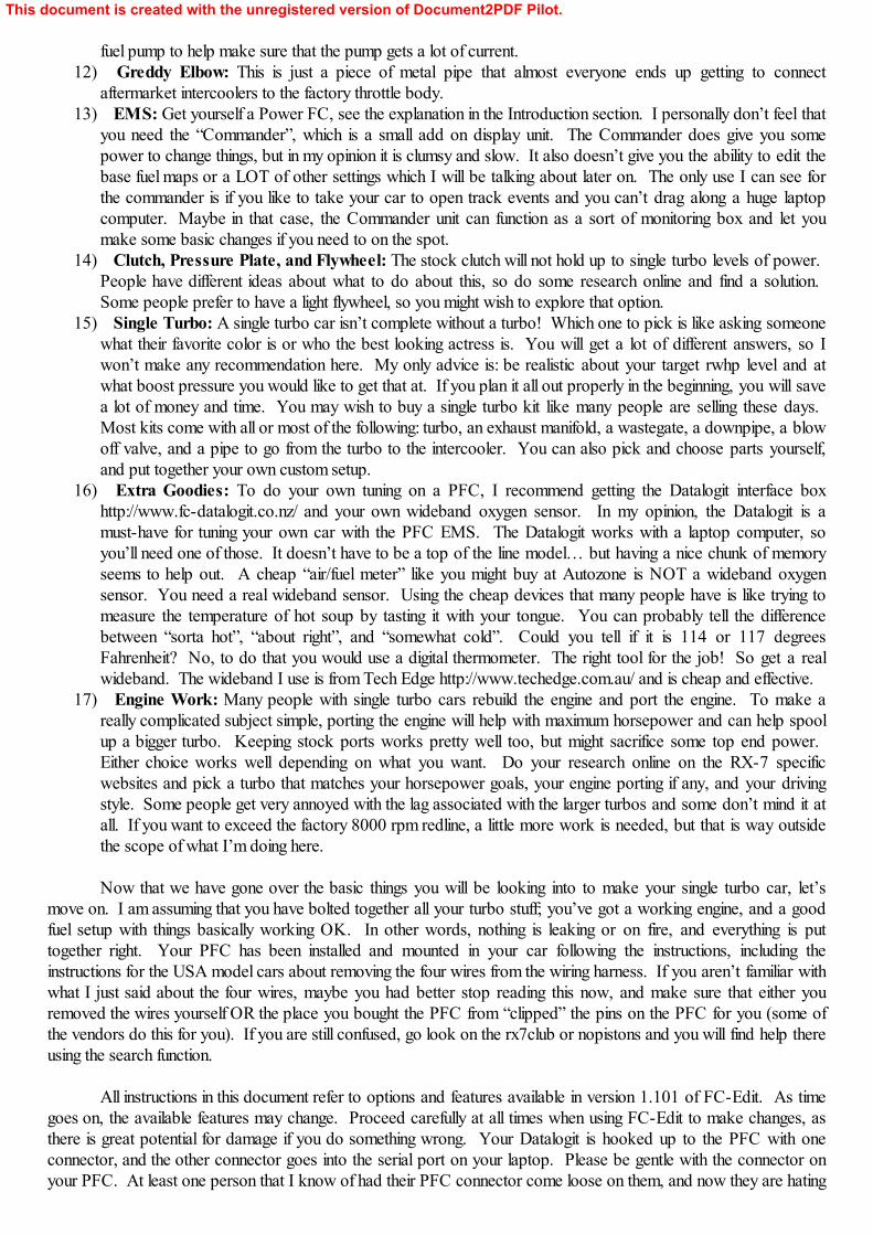
Start up FC-Edit and have a look at the rightmost tab, “FC-Edit”.
This document is created with the unregistered version of Document2PDF Pilot.
Item 1 shows you the version number.
Item 2 has the “Read All” and “Write All” buttons. These two buttons remain at the bottom no matter whattab you select. They read or write all the parameters from or to the Power FC to FC-Edit.
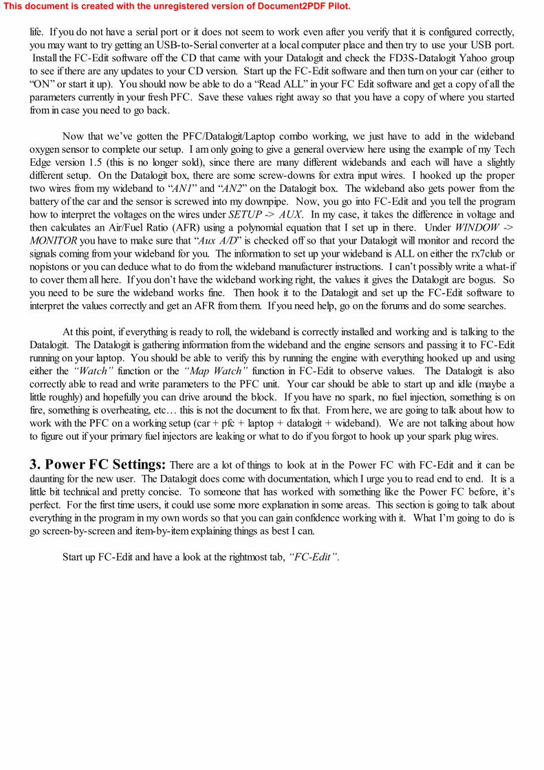
Now, click over to the “Settings 1” tab and look at the picture below.
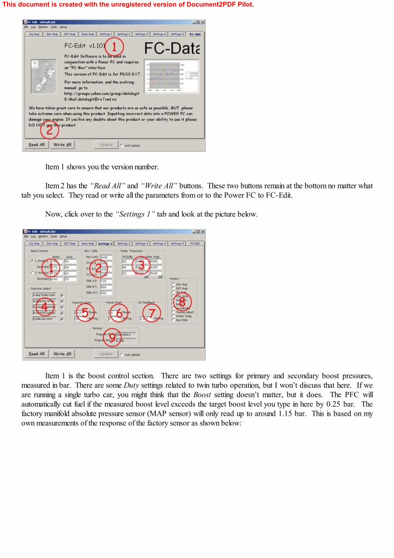
Item 1 is the boost control section. There are two settings for primary and secondary boost pressures,measured in bar. There are some Duty settings related to twin turbo operation, but I won’t discuss that here. If weare running a single turbo car, you might think that the Boost setting doesn’t matter, but it does. The PFC willautomatically cut fuel if the measured boost level exceeds the target boost level you type in here by 0.25 bar. Thefactory manifold absolute pressure sensor (MAP sensor) will only read up to around 1.15 bar. This is based on myown measurements of the response of the factory sensor as shown below:
This document is created with the unregistered version of Document2PDF Pilot.
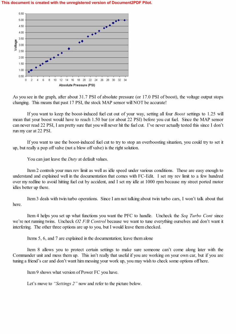
As you see in the graph, after about 31.7 PSI of absolute pressure (or 17.0 PSI of boost), the voltage output stopschanging. This means that past 17 PSI, the stock MAP sensor will NOT be accurate!
If you want to keep the boost-induced fuel cut out of your way, setting all four Boost settings to 1.25 willmean that your boost would have to reach 1.50 bar (or about 22 PSI) before you cut fuel. Since the MAP sensorcan never read 22 PSI, I am pretty sure that you will never hit the fuel cut. I’ve never actually tested this since I don’trun my car at 22 PSI.
If you want to use the boost-induced fuel cut to try to stop an overboosting situation, you could try to set itup, but really a pop off valve (not a blow off valve) is the right solution.
You can just leave the Duty at default values.
Item 2 controls your max rev limit as well as idle speed under various conditions. These are easy enough tounderstand and explained well in the documentation that comes with FC-Edit. I set my rev limit to a few hundredover my redline to avoid hitting fuel cut by accident, and I set my idle at 1000 rpm because my street ported motoridles better up there.
Item 3 deals with twin turbo operations. Since I am not talking about twin turbo cars, I won’t talk about thathere.
Item 4 helps you set up what functions you want the PFC to handle. Uncheck the Seq Turbo Cont sincewe’re not running twins. Uncheck O2 F/B Control because we want to tune everything ourselves and don’t want itinterfering. The other three options are up to you, but I would leave them checked.
Items 5, 6, and 7 are explained in the documentation; leave them alone
Item 8 allows you to protect certain settings to make sure someone can’t come along later with theCommander unit and mess them up. This isn’t really that useful if you are working on your own car, but if you aretuning a friend’s car and don’t want him messing your work up, you may wish to check some options off here.
Item 9 shows what version of Power FC you have.
Let’s move to “Settings 2” now and refer to the picture below.
This document is created with the unregistered version of Document2PDF Pilot.
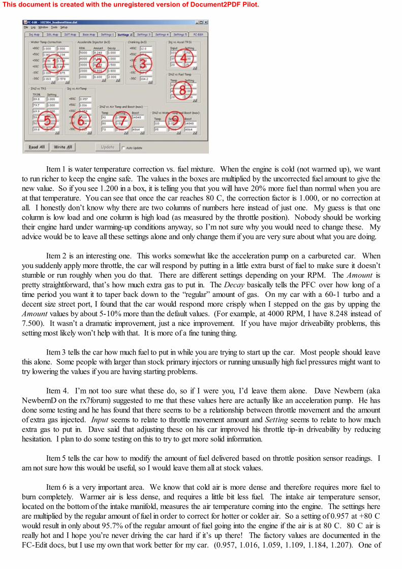
Item 1 is water temperature correction vs. fuel mixture. When the engine is cold (not warmed up), we wantto run richer to keep the engine safe. The values in the boxes are multiplied by the uncorrected fuel amount to give thenew value. So if you see 1.200 in a box, it is telling you that you will have 20% more fuel than normal when you areat that temperature. You can see that once the car reaches 80 C, the correction factor is 1.000, or no correction atall. I honestly don’t know why there are two columns of numbers here instead of just one. My guess is that onecolumn is low load and one column is high load (as measured by the throttle position). Nobody should be workingtheir engine hard under warming-up conditions anyway, so I’m not sure why you would need to change these. Myadvice would be to leave all these settings alone and only change them if you are very sure about what you are doing.
Item 2 is an interesting one. This works somewhat like the acceleration pump on a carbureted car. Whenyou suddenly apply more throttle, the car will respond by putting in a little extra burst of fuel to make sure it doesn’tstumble or run roughly when you do that. There are different settings depending on your RPM. The Amount ispretty straightforward, that’s how much extra gas to put in. The Decay basically tells the PFC over how long of atime period you want it to taper back down to the “regular” amount of gas. On my car with a 60-1 turbo and adecent size street port, I found that the car would respond more crisply when I stepped on the gas by upping theAmount values by about 5-10% more than the default values. (For example, at 4000 RPM, I have 8.248 instead of7.500). It wasn’t a dramatic improvement, just a nice improvement. If you have major driveability problems, thissetting most likely won’t help with that. It is more of a fine tuning thing.
Item 3 tells the car how much fuel to put in while you are trying to start up the car. Most people should leavethis alone. Some people with larger than stock primary injectors or running unusually high fuel pressures might want totry lowering the values if you are having starting problems.
Item 4. I’m not too sure what these do, so if I were you, I’d leave them alone. Dave Newbern (akaNewbernD on the rx7forum) suggested to me that these values here are actually like an acceleration pump. He hasdone some testing and he has found that there seems to be a relationship between throttle movement and the amountof extra gas injected. Input seems to relate to throttle movement amount and Setting seems to relate to how muchextra gas to put in. Dave said that adjusting these on his car improved his throttle tip-in driveability by reducinghesitation. I plan to do some testing on this to try to get more solid information.
Item 5 tells the car how to modify the amount of fuel delivered based on throttle position sensor readings. Iam not sure how this would be useful, so I would leave them all at stock values.
Item 6 is a very important area. We know that cold air is more dense and therefore requires more fuel toburn completely. Warmer air is less dense, and requires a little bit less fuel. The intake air temperature sensor,located on the bottom of the intake manifold, measures the air temperature coming into the engine. The settings hereare multiplied by the regular amount of fuel in order to correct for hotter or colder air. So a setting of 0.957 at +80 Cwould result in only about 95.7% of the regular amount of fuel going into the engine if the air is at 80 C. 80 C air isreally hot and I hope you’re never driving the car hard if it’s up there! The factory values are documented in theFC-Edit docs, but I use my own that work better for my car. (0.957, 1.016, 1.059, 1.109, 1.184, 1.207). One of
This document is created with the unregistered version of Document2PDF Pilot.
the most common ways that RX-7 engines blow is when people drive the car hard when the air temps are elevated,so be careful! The way you know you’ve got good values in here is that your car will give similar AFR readings forthe same P,N values in Map Watch on a hot summer day as on a cool fall night. The air temp is the one parameterthat is most easily changed by the time of day or the change of the seasons, so this one is really important to get agood lock on. I would start with the factory settings, and make relatively small changes if you find that your AFRschange by a lot on a hot day vs. a cold night.
Item 7 applies more adjustments to the amount of fuel injected vs. the temperature and the boost level. I havenever found any need to tinker with these settings, so I would leave them alone.
Item 8 applies a correction to the amount of fuel injection based on the temperature of the fuel itself. I guessthe theory is that hot gasoline is less dense than cooler gasoline so you need another little adjustment. In reality, sincemost single turbo cars have an aftermarket fuel rail, they no longer have any place to mount the factory fuel tempsensor. The best thing to do is just leave the fuel temp sensor OUT of the car altogether and leave the connectordangling there. This will result in a steady value for your fuel temp, and since it is not ever changing, we don’t need todo anything with the adjustments here at all. Leave them stock, this setting will have no effect since you have no tempsensor.
Item 9 is yet another correction to the amount of fuel injected. This time, it is looking at the water temperatureand the boost. You can see from the default setup that at 110 C water temp, the car is going to add in another 7.8%fuel. 110 is already in the “danger zone” for your RX-7, so it’s good that the car is going to try to cool it down byadding even more fuel. I would just leave this setting at stock values. Oh, and I wouldn’t drive the car at 110 Cwater temps for too long.
Going to “Settings 3”, we have the following:
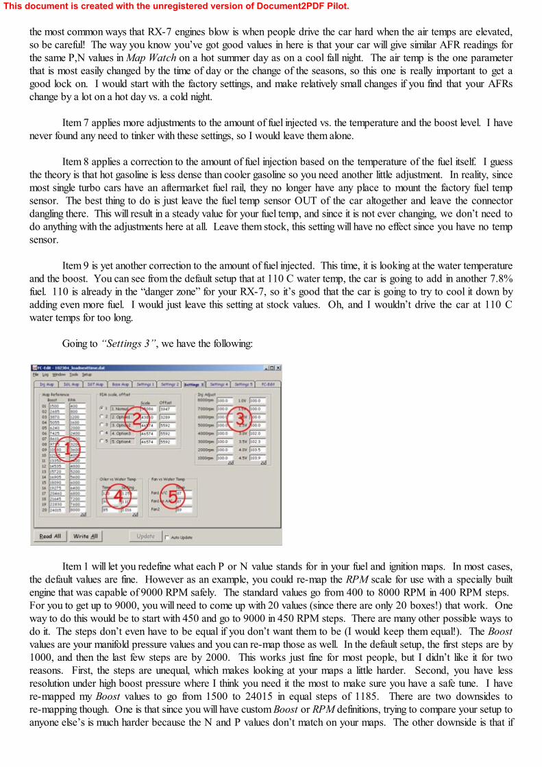
Item 1 will let you redefine what each P or N value stands for in your fuel and ignition maps. In most cases,the default values are fine. However as an example, you could re-map the RPM scale for use with a specially builtengine that was capable of 9000 RPM safely. The standard values go from 400 to 8000 RPM in 400 RPM steps. For you to get up to 9000, you will need to come up with 20 values (since there are only 20 boxes!) that work. Oneway to do this would be to start with 450 and go to 9000 in 450 RPM steps. There are many other possible ways todo it. The steps don’t even have to be equal if you don’t want them to be (I would keep them equal!). The Boostvalues are your manifold pressure values and you can re-map those as well. In the default setup, the first steps are by1000, and then the last few steps are by 2000. This works just fine for most people, but I didn’t like it for tworeasons. First, the steps are unequal, which makes looking at your maps a little harder. Second, you have lessresolution under high boost pressure where I think you need it the most to make sure you have a safe tune. I havere-mapped my Boost values to go from 1500 to 24015 in equal steps of 1185. There are two downsides tore-mapping though. One is that since you will have custom Boost or RPM definitions, trying to compare your setup toanyone else’s is much harder because the N and P values don’t match on your maps. The other downside is that if
This document is created with the unregistered version of Document2PDF Pilot.
you are halfway through tuning and you decide to start changing your Boost and RPM definitions, you have prettymuch undone all your hard work up to that point since nothing will match up quite right in your maps now. My adviceis that if you want to re-map anything, you do it before you get too far along in your tuning. Most people do notre-map, so please don’t feel like you have to do it to make your car run well. It will run fine without re-mapping. There is one more case where you would be forced to re-map. If you have installed an aftermarket MAP sensor andwish to run more than 17 PSI of boost, you need to have maps that go up at least as high as the boost level you planto run. The default setup is only good to about 17 PSI.
Item 2 lets you setup up things for use with different MAP sensors or you can fine tune your current MAPsensor if you want. I run the factory MAP sensor, so I just leave this on the default setting and don’t worry about it. If you install the GM 3 Bar sensor or some other custom sensor you will need to change the values here. Check onthe web for details.
Item 3 lets you make changes to the amount of fuel injected vs. the RPM and vs. the voltage from the MAPsensor (got this tidbit from the FC-Edit manual). Think of these as “big stick” type of changes. For example, putting103.5 in the box next to 8000 RPM will automatically add in 3.5% more fuel when you get near 8000 RPM. This isa very broad method to use to add fuel. I would NOT use these to tune. I would set them all to 100.0 and thennever touch them again. You should do your fuel map tuning on the fuel map, not with these boxes in my opinion. Ifyou have sharp eyes, you’ll notice that in my example screen above, I do have a few on my car that aren’t exactly at100.0. These were like that when I got my PFC from XS Engineering, and since my car runs well now, I’m not goingto go back and try to undo those and then go mess with other things to try to make up for it. For a fresh PFC on acar you haven’t tuned yet, set them all at 100.0 and never touch them is my advice.
Item 4 sets up how your metering oil pump (MOP) responds to increasing water temperatures. When thewater temps start getting high, the car will inject more oil into the rotor housings to try to add more lubrication to keepwear and tear down. We all know that Mazda had to make a compromise here due to emissions standards. Sinceoil does not burn well, they try to put in as little as possible to meet standards. On my car, bumped these up some toput in more oil. I use 1.016, 1.117, and 1.250 at 85, 90, and 120 C. The result I am getting is 1.6% more oil all thetime, with a max of 25% more oil at 120 C. That would be a very hot engine and I hope it never gets up there! As aside note, I also run premix in my gas tank (see the web for more info on what this means) at a mix of ½ ounce twostroke oil per 1 gallon of gasoline. I do this because the MOP dribbles the oil into the combustion chamber via asmall hole located on only one area of the rotor housing. By premixing, I get some oil in with the gasoline and it isdistributed all over the place by the fuel injection system.
Item 5 controls the two cooling fans on the radiator. Most people set them lower than the stock values tohelp keep water temps under control. I have them set at 87, 87, and 89.
The next page is “Settings 4”.
This document is created with the unregistered version of Document2PDF Pilot.
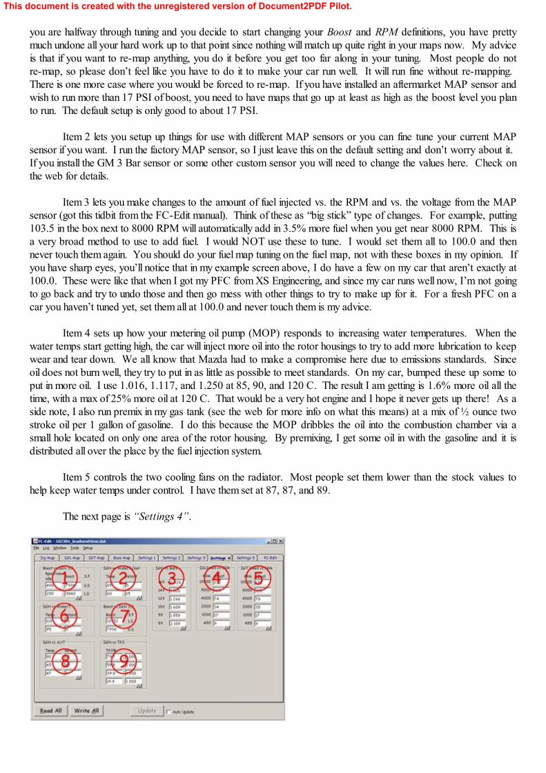
Item 1 I really don’t know anything about; leave it alone.
Item 2 controls your ignition timing when the water temp in the engine is still cold. You don’t want to try toget the max power out of the engine when the engine isn’t warmed up, so the timing is retarded pretty substantially at60 C. Leave these settings alone.
Item 3 is one I don’t know much about. The FC-Edit manual speculates that these settings increase the dwellon the ignition if battery voltage is low. I wouldn’t touch any of these.
Item 4 and 5 are the leading and trailing ignition dwell times. If this were an old car with points anddistributors and things like that, this would affect how long the coil had to charge up after a discharge. I experimentedwith these on my car a bit and found no advantage to changing them. Leave these alone.
Item 6 is important. When the water temperatures climb, the PFC will retard the ignition timing for tworeasons. First, retarding the ignition makes the car make less horsepower and therefore less heat so it may help keepthe temps from going up more. Second, retarding the timing under these stressful conditions might help prevent youfrom blowing your engine. The stock parameters start retarding ignition at 90 C and then ramps up to 6 degrees ofretard at 120 C. I don’t ever want to run my car that hard at temps like 120 C making a lot of rwhp like a singleturbo can make. I have set my values to (110, 10) and (95, 0). What this means is that after I go past 95 C watertemp, it starts retarding the ignition until it reaches a maximum retard of 10 at 110 C. This can help protect my engine,but obviously it does sacrifice power when I’m driving under these conditions. I have never exceeded 95 C on thestreet, only on road courses. So for street driving, I never lose any power. You may or may not feel the need to alterthe stock settings, but at least now you will know what these settings do.
Item 7 is a tricky one. I am not sure what it does, but what I think it does is this: under vacuum conditions,the ignition corrections applied by items 6 and 8 are not applied at all, and under boost conditions, they are applied atfull effect. I would leave them alone.
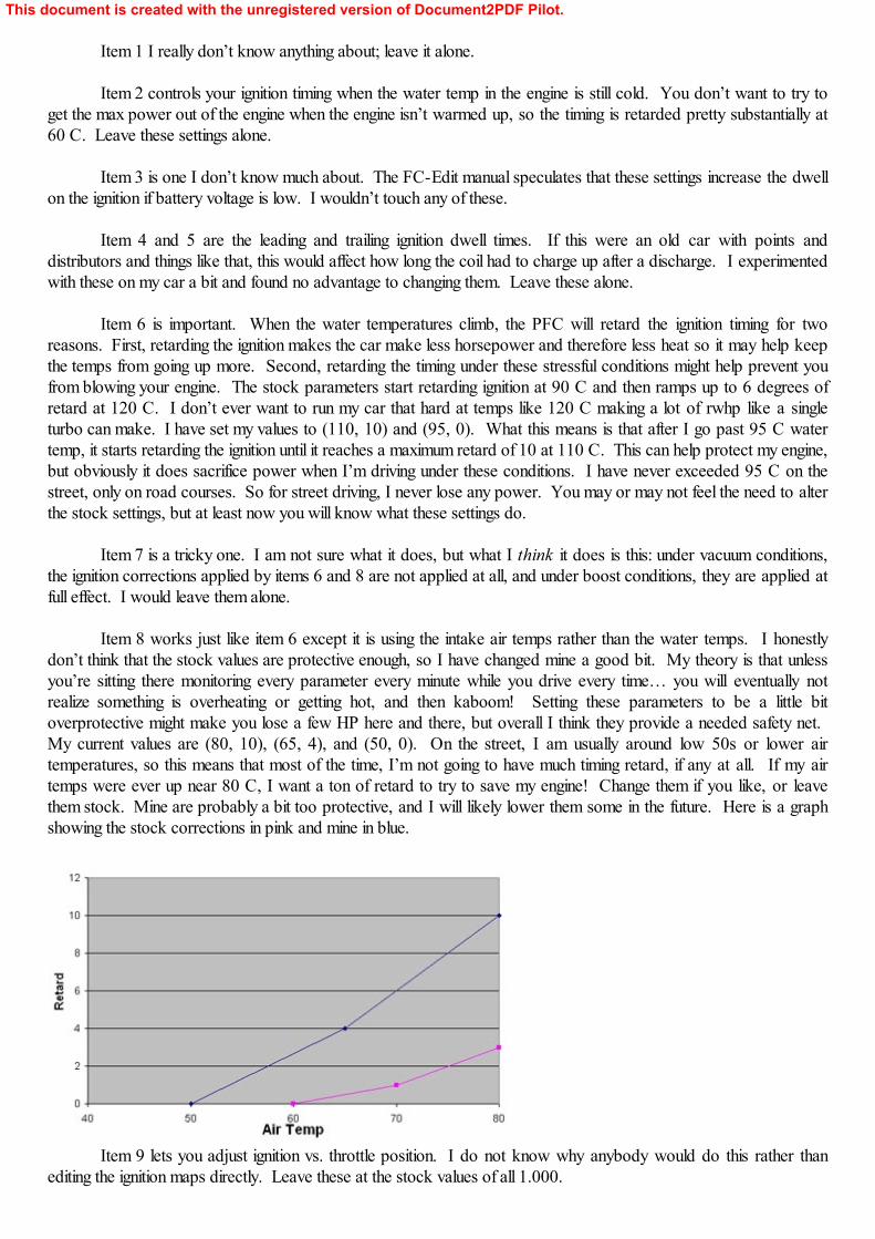
Item 8 works just like item 6 except it is using the intake air temps rather than the water temps. I honestlydon’t think that the stock values are protective enough, so I have changed mine a good bit. My theory is that unlessyou’re sitting there monitoring every parameter every minute while you drive every time… you will eventually notrealize something is overheating or getting hot, and then kaboom! Setting these parameters to be a little bitoverprotective might make you lose a few HP here and there, but overall I think they provide a needed safety net. My current values are (80, 10), (65, 4), and (50, 0). On the street, I am usually around low 50s or lower airtemperatures, so this means that most of the time, I’m not going to have much timing retard, if any at all. If my airtemps were ever up near 80 C, I want a ton of retard to try to save my engine! Change them if you like, or leavethem stock. Mine are probably a bit too protective, and I will likely lower them some in the future. Here is a graphshowing the stock corrections in pink and mine in blue.
Item 9 lets you adjust ignition vs. throttle position. I do not know why anybody would do this rather thanediting the ignition maps directly. Leave these at the stock values of all 1.000.
This document is created with the unregistered version of Document2PDF Pilot.
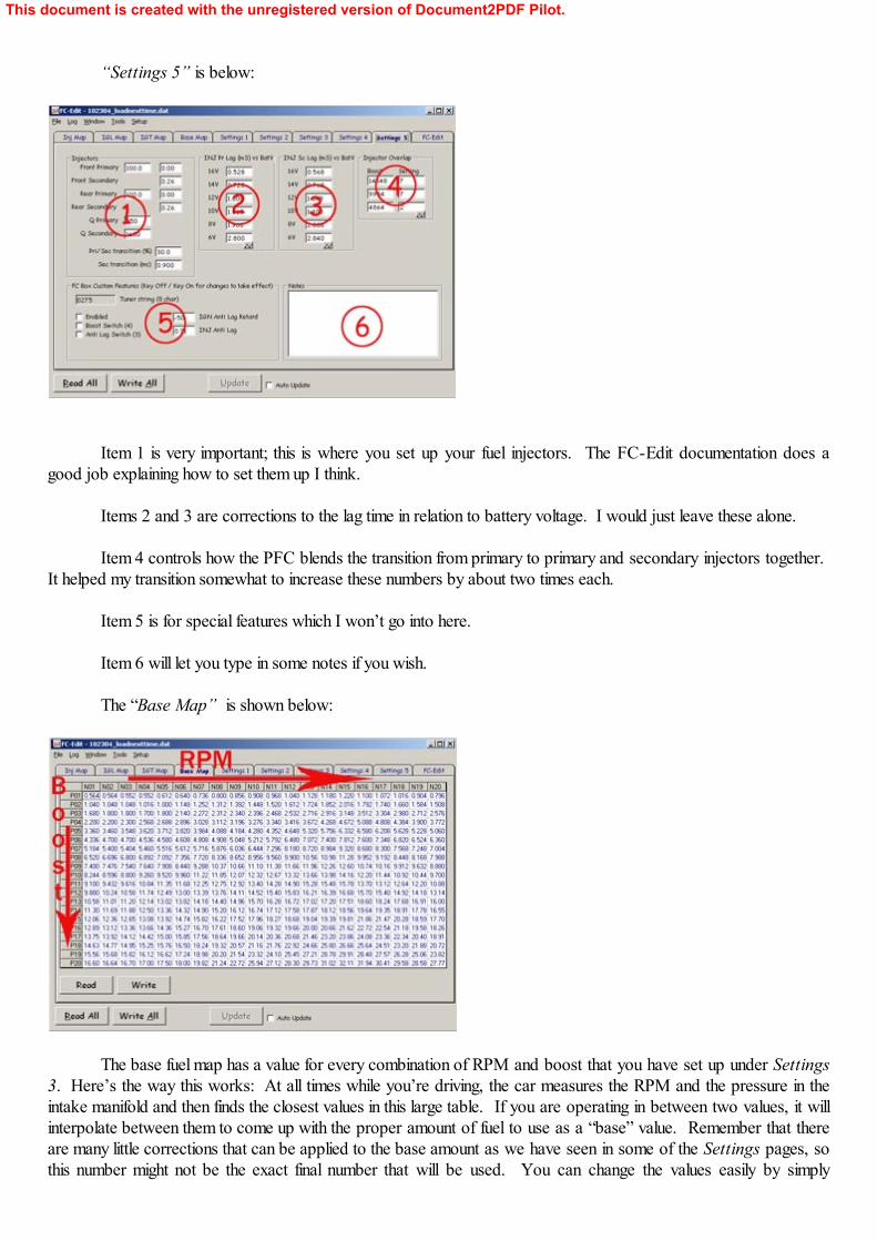
“Settings 5” is below:
Item 1 is very important; this is where you set up your fuel injectors. The FC-Edit documentation does agood job explaining how to set them up I think.
Items 2 and 3 are corrections to the lag time in relation to battery voltage. I would just leave these alone.
Item 4 controls how the PFC blends the transition from primary to primary and secondary injectors together. It helped my transition somewhat to increase these numbers by about two times each.
Item 5 is for special features which I won’t go into here.
Item 6 will let you type in some notes if you wish.
The “Base Map” is shown below:
The base fuel map has a value for every combination of RPM and boost that you have set up under Settings3. Here’s the way this works: At all times while you’re driving, the car measures the RPM and the pressure in theintake manifold and then finds the closest values in this large table. If you are operating in between two values, it willinterpolate between them to come up with the proper amount of fuel to use as a “base” value. Remember that thereare many little corrections that can be applied to the base amount as we have seen in some of the Settings pages, sothis number might not be the exact final number that will be used. You can change the values easily by simply
This document is created with the unregistered version of Document2PDF Pilot.
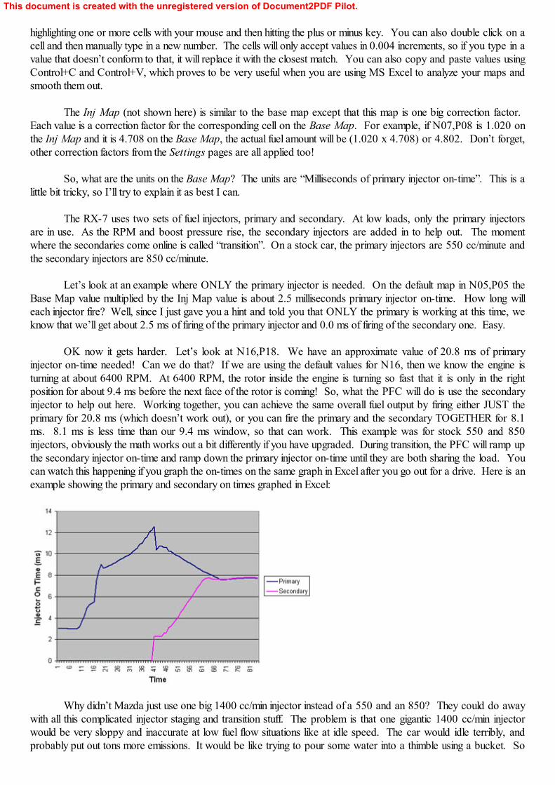
highlighting one or more cells with your mouse and then hitting the plus or minus key. You can also double click on acell and then manually type in a new number. The cells will only accept values in 0.004 increments, so if you type in avalue that doesn’t conform to that, it will replace it with the closest match. You can also copy and paste values usingControl+C and Control+V, which proves to be very useful when you are using MS Excel to analyze your maps andsmooth them out.
The Inj Map (not shown here) is similar to the base map except that this map is one big correction factor. Each value is a correction factor for the corresponding cell on the Base Map. For example, if N07,P08 is 1.020 onthe Inj Map and it is 4.708 on the Base Map, the actual fuel amount will be (1.020 x 4.708) or 4.802. Don’t forget,other correction factors from the Settings pages are all applied too!
So, what are the units on the Base Map? The units are “Milliseconds of primary injector on-time”. This is alittle bit tricky, so I’ll try to explain it as best I can.
The RX-7 uses two sets of fuel injectors, primary and secondary. At low loads, only the primary injectorsare in use. As the RPM and boost pressure rise, the secondary injectors are added in to help out. The momentwhere the secondaries come online is called “transition”. On a stock car, the primary injectors are 550 cc/minute andthe secondary injectors are 850 cc/minute.
Let’s look at an example where ONLY the primary injector is needed. On the default map in N05,P05 theBase Map value multiplied by the Inj Map value is about 2.5 milliseconds primary injector on-time. How long willeach injector fire? Well, since I just gave you a hint and told you that ONLY the primary is working at this time, weknow that we’ll get about 2.5 ms of firing of the primary injector and 0.0 ms of firing of the secondary one. Easy.
OK now it gets harder. Let’s look at N16,P18. We have an approximate value of 20.8 ms of primaryinjector on-time needed! Can we do that? If we are using the default values for N16, then we know the engine isturning at about 6400 RPM. At 6400 RPM, the rotor inside the engine is turning so fast that it is only in the rightposition for about 9.4 ms before the next face of the rotor is coming! So, what the PFC will do is use the secondaryinjector to help out here. Working together, you can achieve the same overall fuel output by firing either JUST theprimary for 20.8 ms (which doesn’t work out), or you can fire the primary and the secondary TOGETHER for 8.1ms. 8.1 ms is less time than our 9.4 ms window, so that can work. This example was for stock 550 and 850injectors, obviously the math works out a bit differently if you have upgraded. During transition, the PFC will ramp upthe secondary injector on-time and ramp down the primary injector on-time until they are both sharing the load. Youcan watch this happening if you graph the on-times on the same graph in Excel after you go out for a drive. Here is anexample showing the primary and secondary on times graphed in Excel:
Why didn’t Mazda just use one big 1400 cc/min injector instead of a 550 and an 850? They could do awaywith all this complicated injector staging and transition stuff. The problem is that one gigantic 1400 cc/min injectorwould be very sloppy and inaccurate at low fuel flow situations like at idle speed. The car would idle terribly, andprobably put out tons more emissions. It would be like trying to pour some water into a thimble using a bucket. So
This document is created with the unregistered version of Document2PDF Pilot.
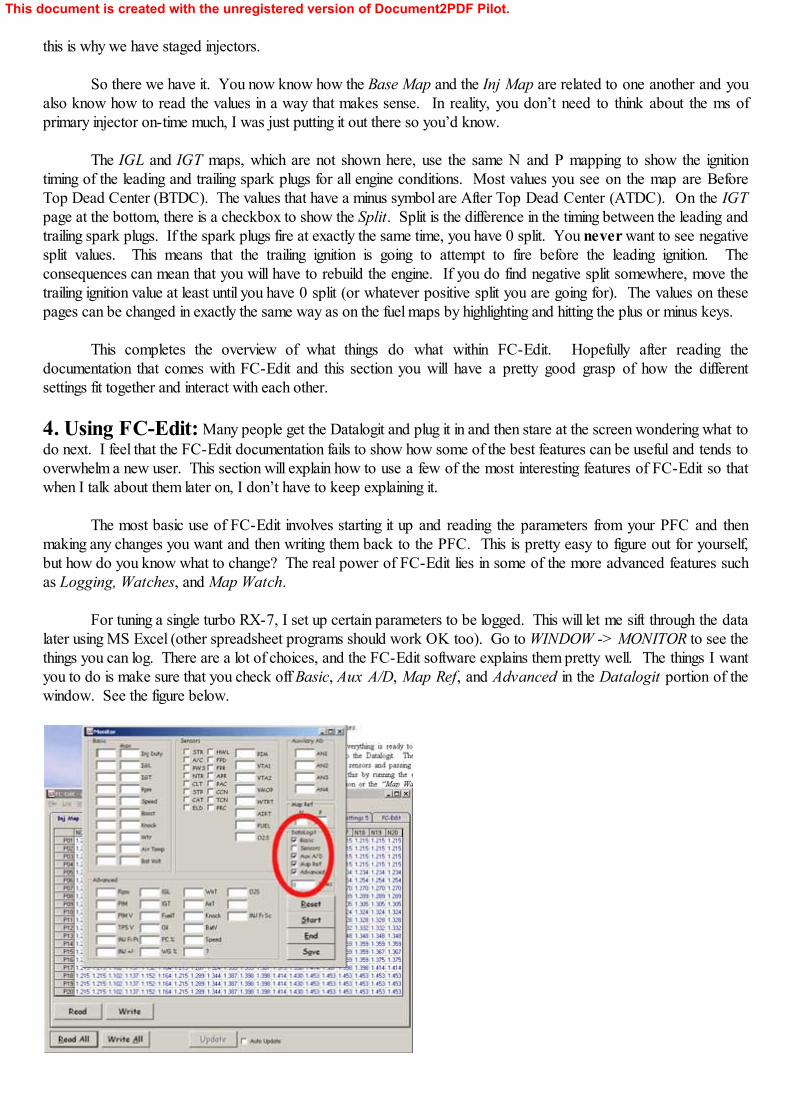
this is why we have staged injectors.
So there we have it. You now know how the Base Map and the Inj Map are related to one another and youalso know how to read the values in a way that makes sense. In reality, you don’t need to think about the ms ofprimary injector on-time much, I was just putting it out there so you’d know.
The IGL and IGT maps, which are not shown here, use the same N and P mapping to show the ignitiontiming of the leading and trailing spark plugs for all engine conditions. Most values you see on the map are BeforeTop Dead Center (BTDC). The values that have a minus symbol are After Top Dead Center (ATDC). On the IGTpage at the bottom, there is a checkbox to show the Split. Split is the difference in the timing between the leading andtrailing spark plugs. If the spark plugs fire at exactly the same time, you have 0 split. You never want to see negativesplit values. This means that the trailing ignition is going to attempt to fire before the leading ignition. Theconsequences can mean that you will have to rebuild the engine. If you do find negative split somewhere, move thetrailing ignition value at least until you have 0 split (or whatever positive split you are going for). The values on thesepages can be changed in exactly the same way as on the fuel maps by highlighting and hitting the plus or minus keys.
This completes the overview of what things do what within FC-Edit. Hopefully after reading thedocumentation that comes with FC-Edit and this section you will have a pretty good grasp of how the differentsettings fit together and interact with each other.
4. Using FC-Edit: Many people get the Datalogit and plug it in and then stare at the screen wondering what todo next. I feel that the FC-Edit documentation fails to show how some of the best features can be useful and tends tooverwhelm a new user. This section will explain how to use a few of the most interesting features of FC-Edit so thatwhen I talk about them later on, I don’t have to keep explaining it.
The most basic use of FC-Edit involves starting it up and reading the parameters from your PFC and thenmaking any changes you want and then writing them back to the PFC. This is pretty easy to figure out for yourself,but how do you know what to change? The real power of FC-Edit lies in some of the more advanced features suchas Logging, Watches, and Map Watch.
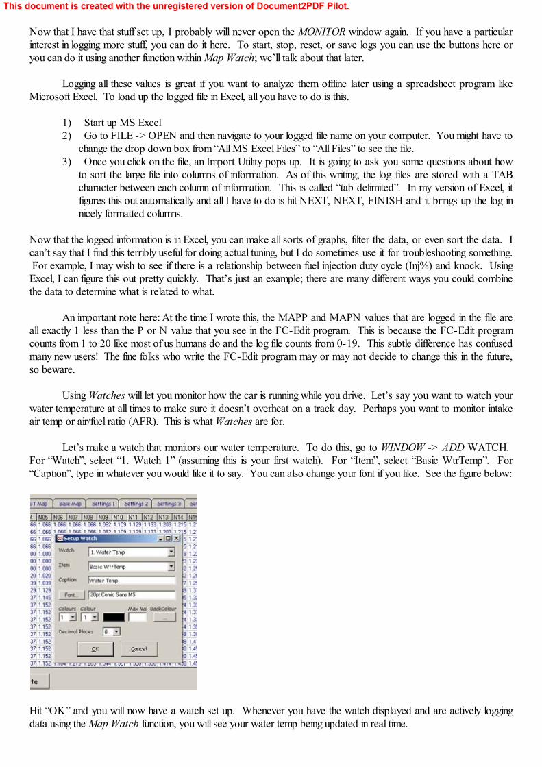
For tuning a single turbo RX-7, I set up certain parameters to be logged. This will let me sift through the datalater using MS Excel (other spreadsheet programs should work OK too). Go to WINDOW -> MONITOR to see thethings you can log. There are a lot of choices, and the FC-Edit software explains them pretty well. The things I wantyou to do is make sure that you check off Basic, Aux A/D, Map Ref, and Advanced in the Datalogit portion of thewindow. See the figure below.
This document is created with the unregistered version of Document2PDF Pilot.
Now that I have that stuff set up, I probably will never open the MONITOR window again. If you have a particularinterest in logging more stuff, you can do it here. To start, stop, reset, or save logs you can use the buttons here oryou can do it using another function within Map Watch; we’ll talk about that later.
Logging all these values is great if you want to analyze them offline later using a spreadsheet program likeMicrosoft Excel. To load up the logged file in Excel, all you have to do is this.
1) Start up MS Excel2) Go to FILE -> OPEN and then navigate to your logged file name on your computer. You might have to
change the drop down box from “All MS Excel Files” to “All Files” to see the file.3) Once you click on the file, an Import Utility pops up. It is going to ask you some questions about how
to sort the large file into columns of information. As of this writing, the log files are stored with a TABcharacter between each column of information. This is called “tab delimited”. In my version of Excel, itfigures this out automatically and all I have to do is hit NEXT, NEXT, FINISH and it brings up the log innicely formatted columns.
Now that the logged information is in Excel, you can make all sorts of graphs, filter the data, or even sort the data. Ican’t say that I find this terribly useful for doing actual tuning, but I do sometimes use it for troubleshooting something. For example, I may wish to see if there is a relationship between fuel injection duty cycle (Inj%) and knock. UsingExcel, I can figure this out pretty quickly. That’s just an example; there are many different ways you could combinethe data to determine what is related to what.
An important note here: At the time I wrote this, the MAPP and MAPN values that are logged in the file areall exactly 1 less than the P or N value that you see in the FC-Edit program. This is because the FC-Edit programcounts from 1 to 20 like most of us humans do and the log file counts from 0-19. This subtle difference has confusedmany new users! The fine folks who write the FC-Edit program may or may not decide to change this in the future,so beware.
Using Watches will let you monitor how the car is running while you drive. Let’s say you want to watch yourwater temperature at all times to make sure it doesn’t overheat on a track day. Perhaps you want to monitor intakeair temp or air/fuel ratio (AFR). This is what Watches are for.
Let’s make a watch that monitors our water temperature. To do this, go to WINDOW -> ADD WATCH. For “Watch”, select “1. Watch 1” (assuming this is your first watch). For “Item”, select “Basic WtrTemp”. For“Caption”, type in whatever you would like it to say. You can also change your font if you like. See the figure below:
Hit “OK” and you will now have a watch set up. Whenever you have the watch displayed and are actively loggingdata using the Map Watch function, you will see your water temp being updated in real time.
This document is created with the unregistered version of Document2PDF Pilot.
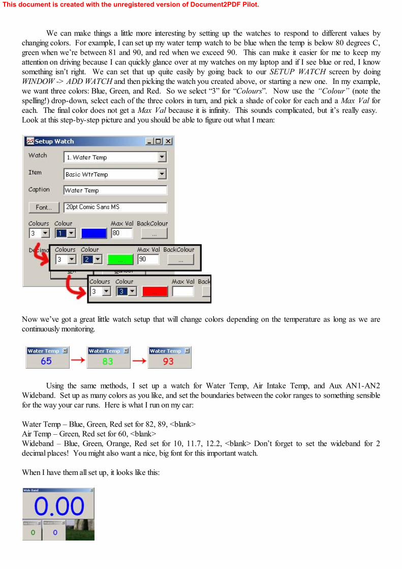
We can make things a little more interesting by setting up the watches to respond to different values bychanging colors. For example, I can set up my water temp watch to be blue when the temp is below 80 degrees C,green when we’re between 81 and 90, and red when we exceed 90. This can make it easier for me to keep myattention on driving because I can quickly glance over at my watches on my laptop and if I see blue or red, I knowsomething isn’t right. We can set that up quite easily by going back to our SETUP WATCH screen by doingWINDOW -> ADD WATCH and then picking the watch you created above, or starting a new one. In my example,we want three colors: Blue, Green, and Red. So we select “3” for “Colours”. Now use the “Colour” (note thespelling!) drop-down, select each of the three colors in turn, and pick a shade of color for each and a Max Val foreach. The final color does not get a Max Val because it is infinity. This sounds complicated, but it’s really easy. Look at this step-by-step picture and you should be able to figure out what I mean:
Now we’ve got a great little watch setup that will change colors depending on the temperature as long as we arecontinuously monitoring.
Using the same methods, I set up a watch for Water Temp, Air Intake Temp, and Aux AN1-AN2Wideband. Set up as many colors as you like, and set the boundaries between the color ranges to something sensiblefor the way your car runs. Here is what I run on my car:
Water Temp – Blue, Green, Red set for 82, 89, <blank>Air Temp – Green, Red set for 60, <blank>Wideband – Blue, Green, Orange, Red set for 10, 11.7, 12.2, <blank> Don’t forget to set the wideband for 2decimal places! You might also want a nice, big font for this important watch.
When I have them all set up, it looks like this:
This document is created with the unregistered version of Document2PDF Pilot.
Now that you’ve gone to all the trouble to set up these beautiful watches, you should save them for futuresessions. FC-Edit will remember the size and location for you. Do WINDOW -> SAVE WATCHES. Remember,the watches only update when you are actively logging data. One way to do this is with the MONITOR window, buta better way is using Map Watch.
Map Watch is a very powerful feature of FC-Edit. Using this feature, you can monitor almost any parameter,and FC-Edit will sort the values and place them in the proper cell on your 20x20 fuel map (or ignition map). This letsyou quickly look at the values and figure out what areas of the map need to be adjusted and by how much.
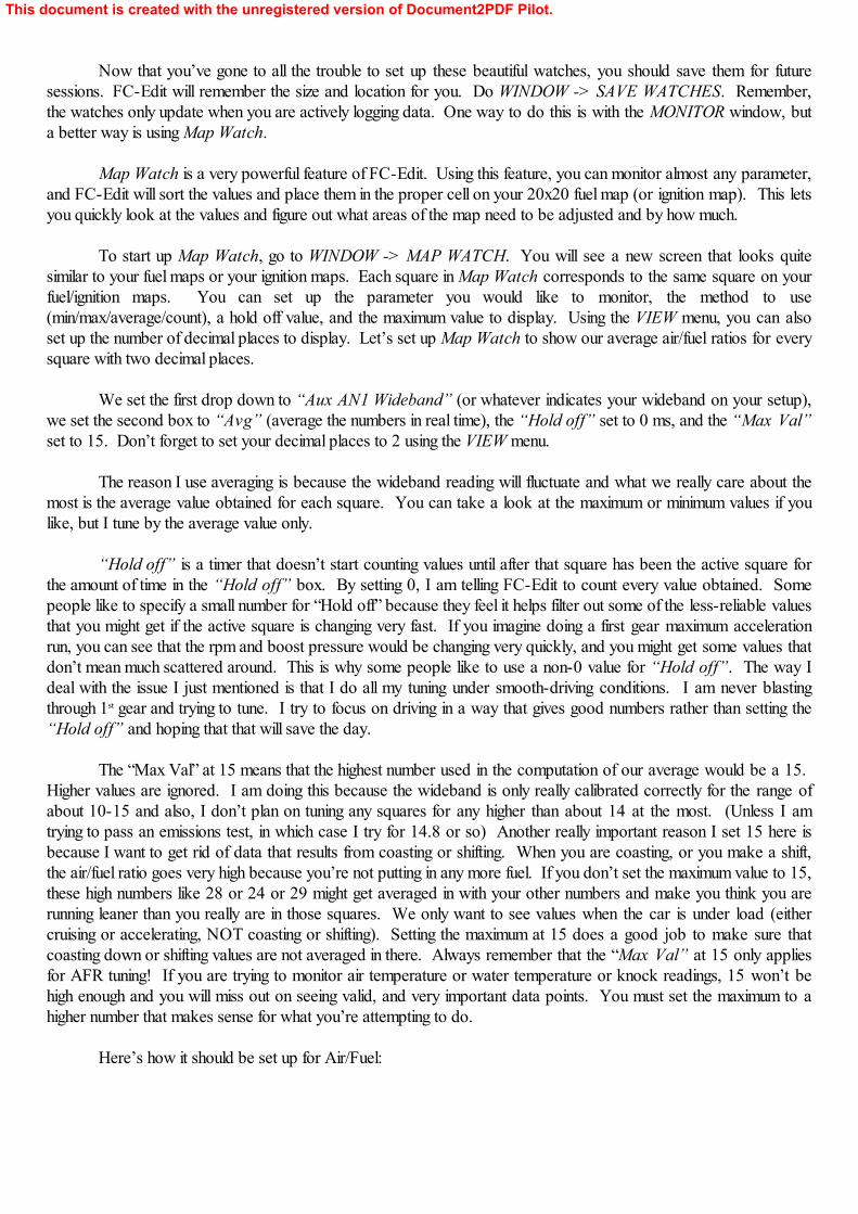
To start up Map Watch, go to WINDOW -> MAP WATCH. You will see a new screen that looks quitesimilar to your fuel maps or your ignition maps. Each square in Map Watch corresponds to the same square on yourfuel/ignition maps. You can set up the parameter you would like to monitor, the method to use(min/max/average/count), a hold off value, and the maximum value to display. Using the VIEW menu, you can alsoset up the number of decimal places to display. Let’s set up Map Watch to show our average air/fuel ratios for everysquare with two decimal places.
We set the first drop down to “Aux AN1 Wideband” (or whatever indicates your wideband on your setup),we set the second box to “Avg” (average the numbers in real time), the “Hold off” set to 0 ms, and the “Max Val”set to 15. Don’t forget to set your decimal places to 2 using the VIEW menu.
The reason I use averaging is because the wideband reading will fluctuate and what we really care about themost is the average value obtained for each square. You can take a look at the maximum or minimum values if youlike, but I tune by the average value only.
“Hold off” is a timer that doesn’t start counting values until after that square has been the active square forthe amount of time in the “Hold off” box. By setting 0, I am telling FC-Edit to count every value obtained. Somepeople like to specify a small number for “Hold off” because they feel it helps filter out some of the less-reliable valuesthat you might get if the active square is changing very fast. If you imagine doing a first gear maximum accelerationrun, you can see that the rpm and boost pressure would be changing very quickly, and you might get some values thatdon’t mean much scattered around. This is why some people like to use a non-0 value for “Hold off”. The way Ideal with the issue I just mentioned is that I do all my tuning under smooth-driving conditions. I am never blastingthrough 1st gear and trying to tune. I try to focus on driving in a way that gives good numbers rather than setting the“Hold off” and hoping that that will save the day.
The “Max Val” at 15 means that the highest number used in the computation of our average would be a 15. Higher values are ignored. I am doing this because the wideband is only really calibrated correctly for the range ofabout 10-15 and also, I don’t plan on tuning any squares for any higher than about 14 at the most. (Unless I amtrying to pass an emissions test, in which case I try for 14.8 or so) Another really important reason I set 15 here isbecause I want to get rid of data that results from coasting or shifting. When you are coasting, or you make a shift,the air/fuel ratio goes very high because you’re not putting in any more fuel. If you don’t set the maximum value to 15,these high numbers like 28 or 24 or 29 might get averaged in with your other numbers and make you think you arerunning leaner than you really are in those squares. We only want to see values when the car is under load (eithercruising or accelerating, NOT coasting or shifting). Setting the maximum at 15 does a good job to make sure thatcoasting down or shifting values are not averaged in there. Always remember that the “Max Val” at 15 only appliesfor AFR tuning! If you are trying to monitor air temperature or water temperature or knock readings, 15 won’t behigh enough and you will miss out on seeing valid, and very important data points. You must set the maximum to ahigher number that makes sense for what you’re attempting to do.
Here’s how it should be set up for Air/Fuel:
This document is created with the unregistered version of Document2PDF Pilot.
Pressing F1, F2, and F3 will start, stop, and save the logged information into a file.
Once you’ve got some values like AFRs logged, you might want to know how to figure out what P and Ncells to modify in your fuel map to bring about a change in the AFR. The picture below shows some logged data(Actually my car passing an emissions test!). If you wanted to make a change to the AFR in the circle in Map Watch,you would want to make a change to the corresponding square in the base fuel map as shown. In addition tomodifying the circled value in the fuel map, you will probably want to make a smaller adjustment to the surroundingcells as well. These are shown in the red rectangle. The majority of your changes will probably only be in the circledcell. You will probably only change the surrounding values a small amount compared to the circled one.
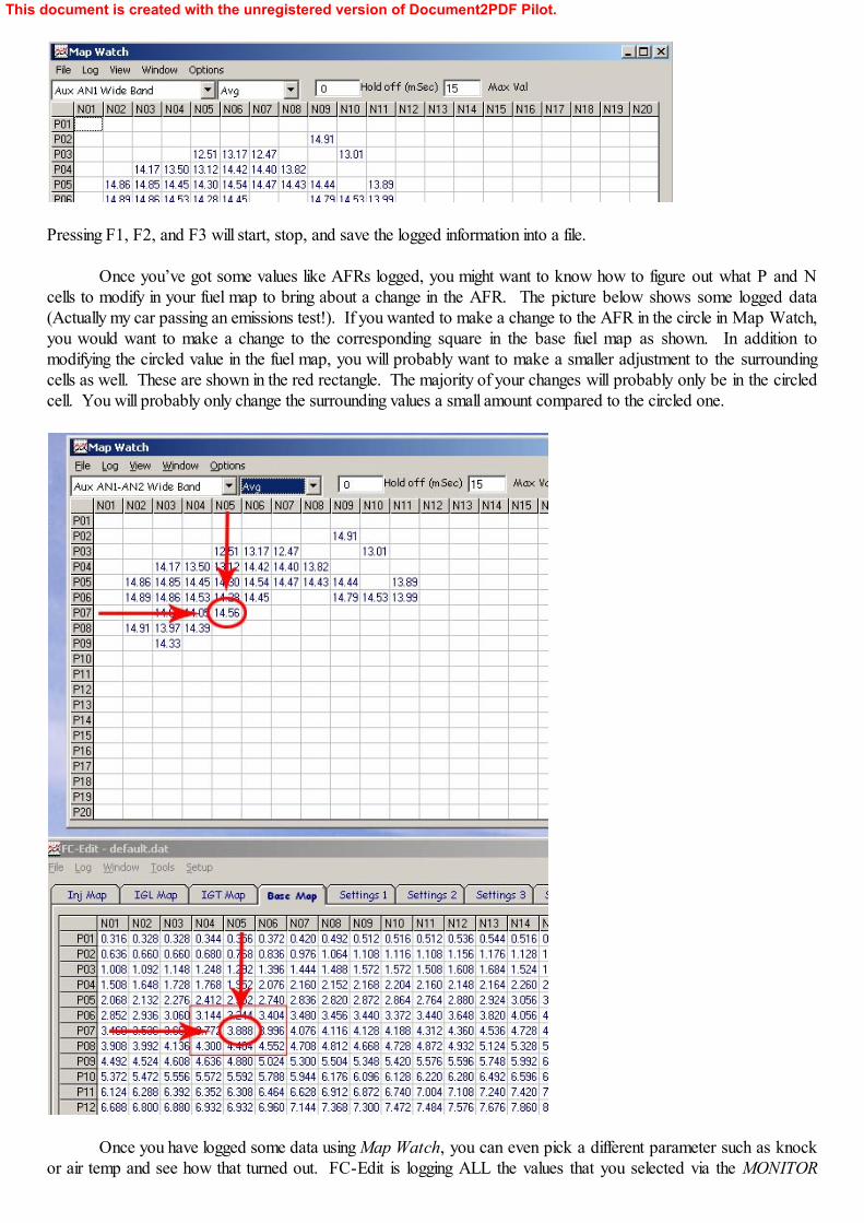
Once you have logged some data using Map Watch, you can even pick a different parameter such as knockor air temp and see how that turned out. FC-Edit is logging ALL the values that you selected via the MONITOR
This document is created with the unregistered version of Document2PDF Pilot.
window at once, even though it may only be displaying one at a time in Map Watch. In the picture below, I looked atmy AFRs, then I decided to check out my injector duty %. I changed the first drop-down box as you can see, Ichanged the decimal point to 0, and I also changed Max Val to 100 since 100 is the highest your injector duty couldever be.
For extra credit, why is it that there is no value in P04, N09 for my wideband, but there is a value of 17% for fuelinjector duty cycle? It is because for the wideband, I have the maximum value set at 15, so whatever values are inthat cell must be greater than 15 and are not displayed.
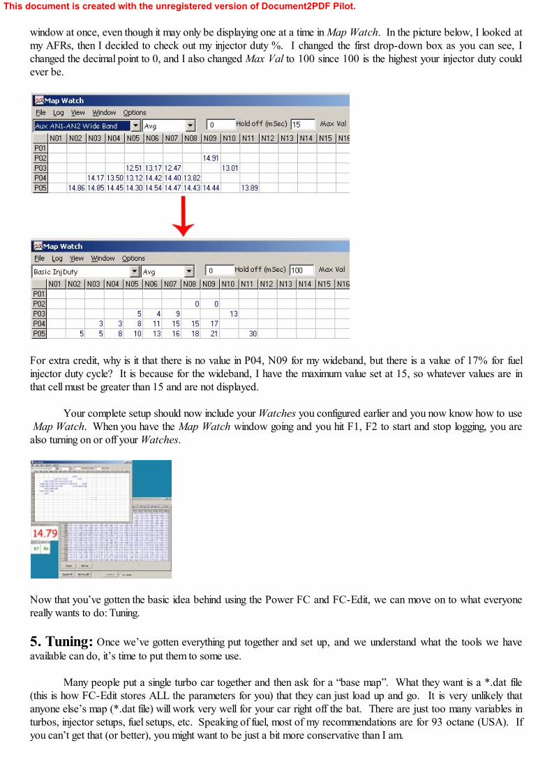
Your complete setup should now include your Watches you configured earlier and you now know how to use Map Watch. When you have the Map Watch window going and you hit F1, F2 to start and stop logging, you arealso turning on or off your Watches.
Now that you’ve gotten the basic idea behind using the Power FC and FC-Edit, we can move on to what everyonereally wants to do: Tuning.
5. Tuning: Once we’ve gotten everything put together and set up, and we understand what the tools we haveavailable can do, it’s time to put them to some use.
Many people put a single turbo car together and then ask for a “base map”. What they want is a *.dat file(this is how FC-Edit stores ALL the parameters for you) that they can just load up and go. It is very unlikely thatanyone else’s map (*.dat file) will work very well for your car right off the bat. There are just too many variables inturbos, injector setups, fuel setups, etc. Speaking of fuel, most of my recommendations are for 93 octane (USA). Ifyou can’t get that (or better), you might want to be just a bit more conservative than I am.
This document is created with the unregistered version of Document2PDF Pilot.
We will assume that you’re starting from a freshly put together RX-7 with a single turbo of some sort and tryto go from there. You’ve got everything bolted up. The car basically will run and not catch on fire or overheat or doother bad things. You have your wideband and Datalogit hooked up and speaking to one another. You know howto navigate the different Settings pages (and what they do), and use tools like Map Watch. We’ll assume the PFCeither has the default *.dat file loaded or possibly it has a *.dat file from someone else that they gave you to help getyou started. In my opinion, starting from someone else’s *.dat file is almost more dangerous than just starting fromscratch; who knows what they have programmed in there.
Do a Read All and save this *.dat file now. If you need to refer back to it for some reason or reload it, youwill have it. I always name my dat files for easy identification later by naming them <date>.dat so I know how old thefile is.
If you are starting from a *.dat file you got from a friend or off the internet, you must check EVERY singleparameter and make sure that it is either at stock default settings or you understand fully what effect it will have beforeyou go on. The advice below mostly is for people starting from a default-configured PFC.
The first thing I would do is make sure that the Map References on Settings 3 are all correct for the expectedRPM range of the engine and the expected boost range. Take a quick glance and make sure they all look good. Ifyou want to go to a model with all equally spaced Boost settings, now is the time to fix these up.
Now look at the PIM Scale on Settings 3. Make sure it is set up right for the MAP sensor you are using. For the factory sensor, you can just leave it at the default setting.
You probably want to adjust the Fan vs. Water Temp settings on Settings 3. I would set them to about (86,87, 90). You can adjust them as you like, but I would definitely lower them from the stock values.
All the Inj Adjust on Settings 3 should be at 100.0; leave them there.
The Oiler vs Water Temp settings on Settings 3 are probably fine at stock values, or you can increase themsomewhat if you want. Don’t get crazy here.
On Settings 4, you should probably leave almost everything at stock values. You may wish to make thetiming retard vs. water temp and air temp more conservative. For IGN vs. WaterT, I use (110, 10) and (95,0) whichis a little more conservative. For IGN vs. AirT, I use (80, 10), (65, 4), and (50, 0) which is probably moreconservative than is needed. You might want to leave this one closer to stock. I would leave the rest of the settingsat default on this page.
On Settings 2, I would probably leave everything alone to start with. You may want to bump up theAccelerate Injector Amounts a bit if you have a ported motor. This will help when you tip-in to the throttle from aroll.
On Settings 1, set your rev limit and idle speeds and disable O2 F/B Control and Seq Turbo Cont (sincewe’re single turbo here). Don’t forget to set all four Boost Control Boost values to at least 0.25 bar higher than yourmaximum intended boost to prevent boost-induced fuel cut.
Head over to Settings 5 and set up your fuel injectors. The FC-Edit documentation explains how to do thispretty well. For 1600 cc/min secondary injectors, I use a lag time of +0.26. The FC-Edit manual explains that thefactory 850’s lag is around 0.77 ms. This means that I think that my upgraded 1600s have an actual lag time of 0.77+ 0.26 or 1.03 ms. People online report good results with different values usually from +0.10 to maybe +0.30. Sometimes, experimentation is the only way to really figure out what works well on a given car. Lag time is theamount of time in milliseconds that it takes for the injector to open and fuel to start flowing out once it sees the signalto open.
Here’s a little background information on injectors and lag. When a fuel injector receives an electrical signal
This document is created with the unregistered version of Document2PDF Pilot.
to open, a small coil generates a magnetic field that moves the pintle. The pintle must pull back, fighting against thefuel pressure to open. This takes a little bit of time to happen… the lag time. Larger injectors are also slower toopen. Another technical bit that comes into play here is the difference in the two major types of injector. Someinjectors are called “peak and hold” and some are called “saturated”. Look them up on the web if you really want toget technical on the differences. The basic difference is that the stock 850s are saturated type and some aftermarketones like my 1600s are peak and hold. Saturated injectors work using a steady current to open them. They are alittle bit slower to open. Peak and hold type will usually have a lower resistance and work by having a quick zap ofhigh current to open them quickly, and then the current drops down to hold it open. These are faster, but require theproper EMS to run them. The problem is that a lot of us are putting the 1600 cc/min peak and hold type of injectorsin our cars and then expecting the saturated-type PFC to control them properly. If you just try to plug the peak andhold 1600s into your PFC and go, you are putting a lot of current through the driver circuits in the PFC because theywere not designed to work with the lower resistance peak and hold injectors.
To protect the PFC, most people wire a resistor in series with the new low resistance injectors. This will helplimit the current flow. The one downside to this is that it will cause your peak and hold injectors to open more slowlythan they were designed for. Many people use one 10 ohm, 10 watt resistor per low resistance injector. I use a 10ohm, 20 watt resistor because I’m conservative. Resistors like these can be purchased very cheaply at Radio Shack. Solder all the connections and test them with your voltmeter before running the car. A failed injector circuit will mostlikely blow your engine. I highly recommend that you do not run low resistance (2-6 ohm) injectors with no resistors! If you want to explore more on the topic on your own, search on the online forums to learn what other people havedone.
In order to help make sure your injectors can open properly and to help make sure you have a nice idle, Irecommend setting the base fuel pressure at 36 PSI when the manifold pressure is at 0 PSI (equal to atmosphericpressure). The way to do this is to start the car up, and then disconnect the boost compensation vacuum hose onyour aftermarket fuel pressure regulator. After setting the fuel pressure like this, reconnect the boost compensationport on your fuel pressure regulator to the intake manifold. If you are still running the stock regulator, none of theaforementioned steps are needed, as the factory setting is around 36 PSI. If everything is hooked up correctly, yourfuel pressure at idle speed will be somewhere around 30 PSI.
For cars with a 550/1600 injector setup, I would try setting the Pri/Sec Transition % to 30.0% and the SecTransition to 0.900 ms to start out. These two settings can be some of the most frustrating to try to get right. Everyone seems to have their favorite settings, and there is definitely some experimenting that you will have to do toget them right. Cars that have a closer to stock setup such as 550/1300 will probably do better with settings closer tostock values. When you get this setting figured out, the car will run smoothly up through the RPM as you drive andthere will be minimal stumbling or bucking. When you don’t have it right, the car will probably buck or hesitatehorribly when the secondary injectors try to kick in.
When your car has a bucking or stumbling problem under certain conditions, the first thing to do is figure out ifit is a transition problem or some other problem. The easiest way to figure this out is to set up a Watch where theItem is Advanced InjFrSc. This is the secondary injector on time. Now drive around and see if the bucking occursevery time the secondaries start to phase in. If it does, you know you have to work on your transition.
For the timing map, I would NOT start with the stock map on a single turbo car, especially if the engine has astreet port. Single turbo cars (especially with a street port) will need less advanced timing to run safely.
Overall, you should be tuning the air/fuel ratio (AFR) first, and then tuning the timing second on a dyno. But inorder to go out and do any tuning at all, you should start with some nice and safe timing numbers. So the basic idea iswe set up the PFC first for our injectors, etc, then we get a decent and safe timing map loaded. Then after that, yougo out and tune your AFRs where you want them. Then at the end, you hit the dyno and see if you can tweak thetiming a bit to fix up any problem areas.
So, to start out with timing, everywhere in the vacuum range (P01-P10 on the default settings), you shouldjust stick with the default PFC values for IGL. Under higher rpm, higher boost areas, you will want to dial back thetiming at least a few degrees (more on a ported motor).
This document is created with the unregistered version of Document2PDF Pilot.
It is hard to make exact recommendations, but you should be pretty safe with an IGL map that runs stockvalues under vacuum conditions, and then smoothly pulls back the timing to around 12 or 13 deg BTDC at yourtorque peak by 15 PSI boost. For a 13B engine your torque peak will probably be somewhere near N15 if youdon’t know. After you have passed your torque peak, you can add another bit of timing, but not too much! You willwant to smooth the factory map out as much as possible and take out odd values that don’t make sense.
The most basic concepts behind timing are pretty simple. In an engine, there is a time delay between whenthe spark plug ignites the mixture and when the pressure front from the burning fuel/air mixture hits against the rotor. Most people think that the mixture in the rotor housing explodes, but it’s really more of a fast but controlled burning. If we ignite the mixture at just the right moment, the pressure front from the burn will start pushing on the rotor at theoptimal moment and turn the engine and make lots of power. If we wait too late, we won’t get the maximum forceover as long a time as possible. If we ignite too early, the pressure front will actually hit the rotor at the wrong timeand try to turn the engine backwards. This is extremely hard on the engine. Now that we know this, we can maketwo generalizations. The first is that the faster the rotor is turning, the earlier we have to fire off the spark plug in orderto get the pressure front to hit the rotor at the right time. This is just like when you “lead” a target when shooting itwith a gun or when you throw a football to someone that is running. So as the RPM rises, we expect that our timingwill increase (assuming boost pressure remains the same). The other generalization we can make is that as the boostpressure rises, we must reduce the timing value (assuming this time that RPM is constant). This is because underhigher boost pressures, the molecules of the fuel/air mixture are more closely packed together and the pressure wavefrom the burn will travel more quickly towards the rotor.
In general, when the boost goes up, the timing goes down and when the RPM goes up, the timing goes upalso.
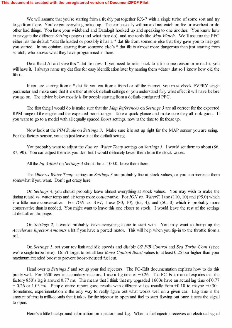
Now that we’ve established that general trend, you might be able to go through your IGL timing map andpick out oddball values and make a smooth and safe map. If you see a timing map that looks something like this,what sticks out?
I highlighted a few bogus ones for you. Cells like these are sloppy and could potentially cause damage. You shouldsmooth the values out to make things more reasonable. For example, I would probably change the 28 to 22. Thatwould be a lot more reasonable don’t you think? Ideally, you will make your starting out IGL map look prettysmooth with no odd numbers in it. Most of the time, you’ll just be bumping them by 1 or 2 degrees to smooth them. The only exception is from about 6000 and up under boost, where you will lower the values by more than just 1 or 2.
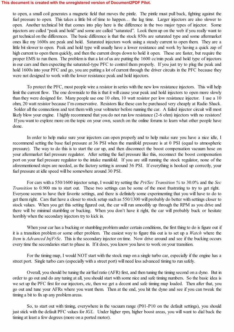
Looking at the picture below, I’ve highlighted some general areas on the IGL map. This is for the default Nand P mappings. If you have changed yours, your areas might turn out to be a bit different.
This document is created with the unregistered version of Document2PDF Pilot.
The green area is the idling area. Some of the timing values look a little funny in there. I wouldn’t try tochange them too much, at least not right away. Nobody blows their engine at idle.
The light purple area at the lower left is generally about the boundary of where a single turbo car will makeboost. Areas in the light purple are not going to be used on most single turbo cars because they won’t make enoughboost to get into those areas. To more precisely define this area for your specific car, you can use Map Watch. Youcan see areas you never use because there will never be any logged values there.
The dark blue area is vacuum/cruising range. Most people don’t make changes to the timing in this rangeexcept just a degree or two here or there to smooth their map.
The red area is the most critical area. This map shows the default map with the default timing values. Youcan see that the timing is going up to 20-25 degrees around P17 or P18 range at high RPM. This is around 15 PSI orso. We definitely don’t want this much timing for a single turbo car. You should work out a nice safe starting mapwhere those 20-25 values in P18-P19 are down around 12-13 range. This definitely won’t make the most power,but it is a lot safer than 20-25 and will let us work on AFRs first. Later, on a dyno, you will probably find that 12-13is too conservative and somewhere around 15 will work better. Remember to smooth everything out. So while youmight have a 12 or 13 in P18,N20, you may have something like a 15 in P15,N20. These are just some ball parkfigures, I’m not going to try to dictate every cell on your timing map because every car is different.
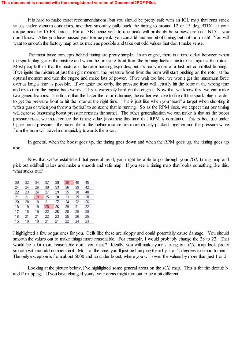
Work on this map until you have something decent looking. I think you will find that using MS Excel to graphthe IGL table can help you smooth things out. Your first attempts might take a while, but that’s OK. It’s important togo slowly when you’re learning. I encourage you to look at other people’s maps and just check out what they’redoing too.
Once you have a nice IGL map, setting up the IGT map is very easy. Click over to the IGT page and thencheck off the Display IGL-IGT (Split) box. This will show the difference in the leading and trailing plug timing. Adjust every cell until the split (NOT the actual timing number itself, you want to set the SPLIT) is set at 15 in eachcell.
This document is created with the unregistered version of Document2PDF Pilot.
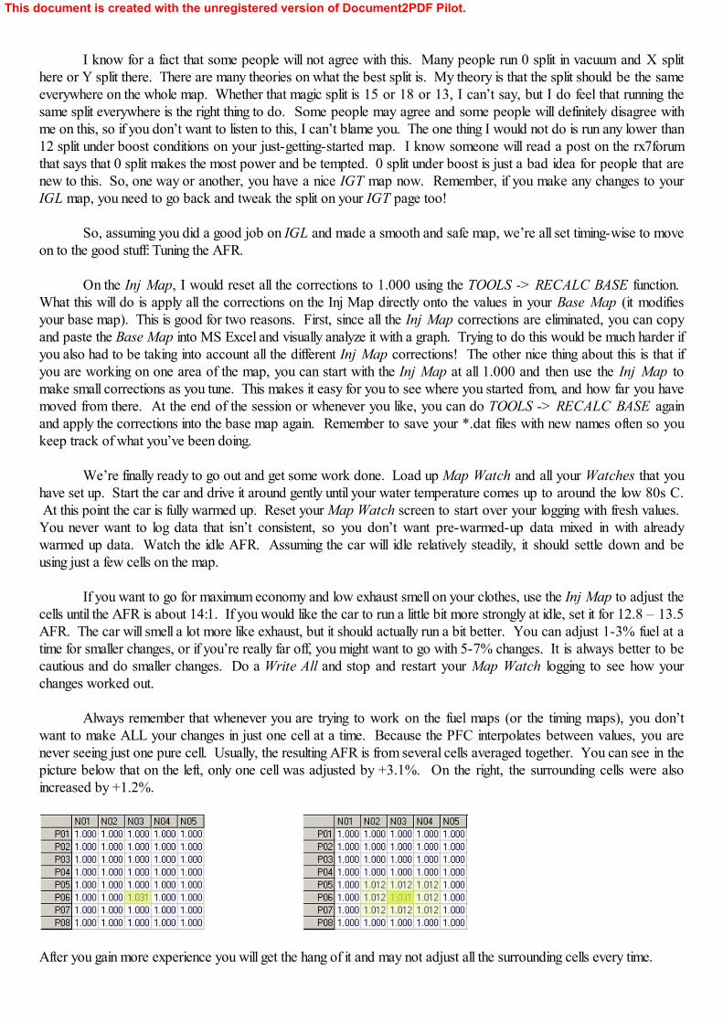
I know for a fact that some people will not agree with this. Many people run 0 split in vacuum and X splithere or Y split there. There are many theories on what the best split is. My theory is that the split should be the sameeverywhere on the whole map. Whether that magic split is 15 or 18 or 13, I can’t say, but I do feel that running thesame split everywhere is the right thing to do. Some people may agree and some people will definitely disagree withme on this, so if you don’t want to listen to this, I can’t blame you. The one thing I would not do is run any lower than12 split under boost conditions on your just-getting-started map. I know someone will read a post on the rx7forumthat says that 0 split makes the most power and be tempted. 0 split under boost is just a bad idea for people that arenew to this. So, one way or another, you have a nice IGT map now. Remember, if you make any changes to yourIGL map, you need to go back and tweak the split on your IGT page too!
So, assuming you did a good job on IGL and made a smooth and safe map, we’re all set timing-wise to moveon to the good stuff: Tuning the AFR.
On the Inj Map, I would reset all the corrections to 1.000 using the TOOLS -> RECALC BASE function. What this will do is apply all the corrections on the Inj Map directly onto the values in your Base Map (it modifiesyour base map). This is good for two reasons. First, since all the Inj Map corrections are eliminated, you can copyand paste the Base Map into MS Excel and visually analyze it with a graph. Trying to do this would be much harder ifyou also had to be taking into account all the different Inj Map corrections! The other nice thing about this is that ifyou are working on one area of the map, you can start with the Inj Map at all 1.000 and then use the Inj Map tomake small corrections as you tune. This makes it easy for you to see where you started from, and how far you havemoved from there. At the end of the session or whenever you like, you can do TOOLS -> RECALC BASE againand apply the corrections into the base map again. Remember to save your *.dat files with new names often so youkeep track of what you’ve been doing.
We’re finally ready to go out and get some work done. Load up Map Watch and all your Watches that youhave set up. Start the car and drive it around gently until your water temperature comes up to around the low 80s C. At this point the car is fully warmed up. Reset your Map Watch screen to start over your logging with fresh values. You never want to log data that isn’t consistent, so you don’t want pre-warmed-up data mixed in with alreadywarmed up data. Watch the idle AFR. Assuming the car will idle relatively steadily, it should settle down and beusing just a few cells on the map.
If you want to go for maximum economy and low exhaust smell on your clothes, use the Inj Map to adjust thecells until the AFR is about 14:1. If you would like the car to run a little bit more strongly at idle, set it for 12.8 – 13.5AFR. The car will smell a lot more like exhaust, but it should actually run a bit better. You can adjust 1-3% fuel at atime for smaller changes, or if you’re really far off, you might want to go with 5-7% changes. It is always better to becautious and do smaller changes. Do a Write All and stop and restart your Map Watch logging to see how yourchanges worked out.
Always remember that whenever you are trying to work on the fuel maps (or the timing maps), you don’twant to make ALL your changes in just one cell at a time. Because the PFC interpolates between values, you arenever seeing just one pure cell. Usually, the resulting AFR is from several cells averaged together. You can see in thepicture below that on the left, only one cell was adjusted by +3.1%. On the right, the surrounding cells were alsoincreased by +1.2%.
After you gain more experience you will get the hang of it and may not adjust all the surrounding cells every time.
This document is created with the unregistered version of Document2PDF Pilot.
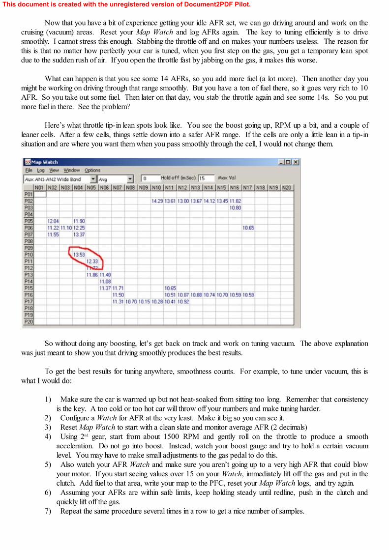
Now that you have a bit of experience getting your idle AFR set, we can go driving around and work on thecruising (vacuum) areas. Reset your Map Watch and log AFRs again. The key to tuning efficiently is to drivesmoothly. I cannot stress this enough. Stabbing the throttle off and on makes your numbers useless. The reason forthis is that no matter how perfectly your car is tuned, when you first step on the gas, you get a temporary lean spotdue to the sudden rush of air. If you open the throttle fast by jabbing on the gas, it makes this worse.
What can happen is that you see some 14 AFRs, so you add more fuel (a lot more). Then another day youmight be working on driving through that range smoothly. But you have a ton of fuel there, so it goes very rich to 10AFR. So you take out some fuel. Then later on that day, you stab the throttle again and see some 14s. So you putmore fuel in there. See the problem?
Here’s what throttle tip-in lean spots look like. You see the boost going up, RPM up a bit, and a couple ofleaner cells. After a few cells, things settle down into a safer AFR range. If the cells are only a little lean in a tip-insituation and are where you want them when you pass smoothly through the cell, I would not change them.
So without doing any boosting, let’s get back on track and work on tuning vacuum. The above explanationwas just meant to show you that driving smoothly produces the best results.
To get the best results for tuning anywhere, smoothness counts. For example, to tune under vacuum, this iswhat I would do:
1) Make sure the car is warmed up but not heat-soaked from sitting too long. Remember that consistencyis the key. A too cold or too hot car will throw off your numbers and make tuning harder.
2) Configure a Watch for AFR at the very least. Make it big so you can see it.3) Reset Map Watch to start with a clean slate and monitor average AFR (2 decimals)4) Using 2nd gear, start from about 1500 RPM and gently roll on the throttle to produce a smooth
acceleration. Do not go into boost. Instead, watch your boost gauge and try to hold a certain vacuumlevel. You may have to make small adjustments to the gas pedal to do this.
5) Also watch your AFR Watch and make sure you aren’t going up to a very high AFR that could blowyour motor. If you start seeing values over 15 on your Watch, immediately lift off the gas and put in theclutch. Add fuel to that area, write your map to the PFC, reset your Map Watch logs, and try again.
6) Assuming your AFRs are within safe limits, keep holding steady until redline, push in the clutch andquickly lift off the gas.
7) Repeat the same procedure several times in a row to get a nice number of samples.
This document is created with the unregistered version of Document2PDF Pilot.
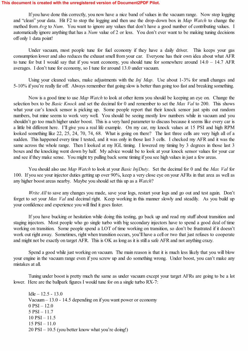
If you have done this correctly, you now have a nice band of values in the vacuum range. Now stop loggingand “clean” your data. Hit F2 to stop the logging and then use the drop-down box in Map Watch to change themethod from Avg to Num. You want to ignore any values that don’t have a good number of contributing values. Iautomatically ignore anything that has a Num value of 2 or less. You don’t ever want to be making tuning decisionsoff only 1 data point!
Under vacuum, most people tune for fuel economy if they have a daily driver. This keeps your gasconsumption lower and also reduces the exhaust smell from your car. Everyone has their own idea about what AFRto tune for but I would say that if you want economy, you should tune for somewhere around 14.0 – 14.7 AFRaverages. I don’t tune for economy, so I tune for around 13.0 under vacuum.
Using your cleaned values, make adjustments with the Inj Map. Use about 1-3% for small changes and5-10% if you’re really far off. Always remember that going slow is better than going too fast and breaking something.
Now is a good time to use Map Watch to look at other items you should be keeping an eye on. Change theselection box to be Basic Knock and set the decimal for 0 and remember to set the Max Val to 200. This showswhat your car’s knock sensor is picking up. Some people report that their knock sensor just spits out randomnumbers, but mine seems to work very well. You should be seeing mostly low numbers while in vacuum and youshouldn’t go too much higher under boost. This is a very hard parameter to discuss because it seems like every car isa little bit different here. I’ll give you a real life example. On my car, my knock values at 15 PSI and high RPMlooked something like 22, 25, 24, 70, 74, 68. What is going on there? The last three cells are very high all of asudden. This happened every time I tested, and it was only in those last 3 cells. I checked my AFR and it was thesame across the whole range. Then I looked at my IGL timing. I lowered my timing by 3 degrees in those last 3boxes and the knocking went down by half. My advice would be to look at your knock sensor values for your carand see if they make sense. You might try pulling back some timing if you see high values in just a few areas.
You should also use Map Watch to look at your Basic InjDuty. Set the decimal for 0 and the Max Val for100. If you see your injector duties getting up over 90%, keep a very close eye on your AFRs in that area as well asany higher boost areas nearby. Maybe you should set this up as a Watch?
Write All to save any changes you made, save your logs, restart your logs and go out and test again. Don’tforget to set your Max Val and decimal right. Keep working in this manner slowly and steadily. As you build upyour confidence and experience you will find it goes faster.
If you have bucking or hesitation while doing this testing, go back up and read my stuff about transition andstaging injectors. Most people who go single turbo with big secondary injectors have to spend a good deal of timeworking on transition. Some people spend a LOT of time working on transition, so don’t be frustrated if it doesn’twork out right away. Sometimes, right when transition occurs, you’ll have a cell or two that just refuses to cooperateand might not be exactly on target AFR. This is OK as long as it is still a safe AFR and not anything crazy.
Spend a good while just working on vacuum. The main reason is that it is much less likely that you will blowyour engine in the vacuum range even if you screw up and do something wrong. Under boost, you can’t make anymistakes at all.
Tuning under boost is pretty much the same as under vacuum except your target AFRs are going to be a lotlower. Here are the ballpark figures I would tune for on a single turbo RX-7:
Idle – 12.5 - 13.0Vacuum – 13.0 - 14.5 depending on if you want power or economy0 PSI – 12.05 PSI – 11.710 PSI – 11.515 PSI – 11.020 PSI – 10.5 (you better know what you’re doing!)
This document is created with the unregistered version of Document2PDF Pilot.
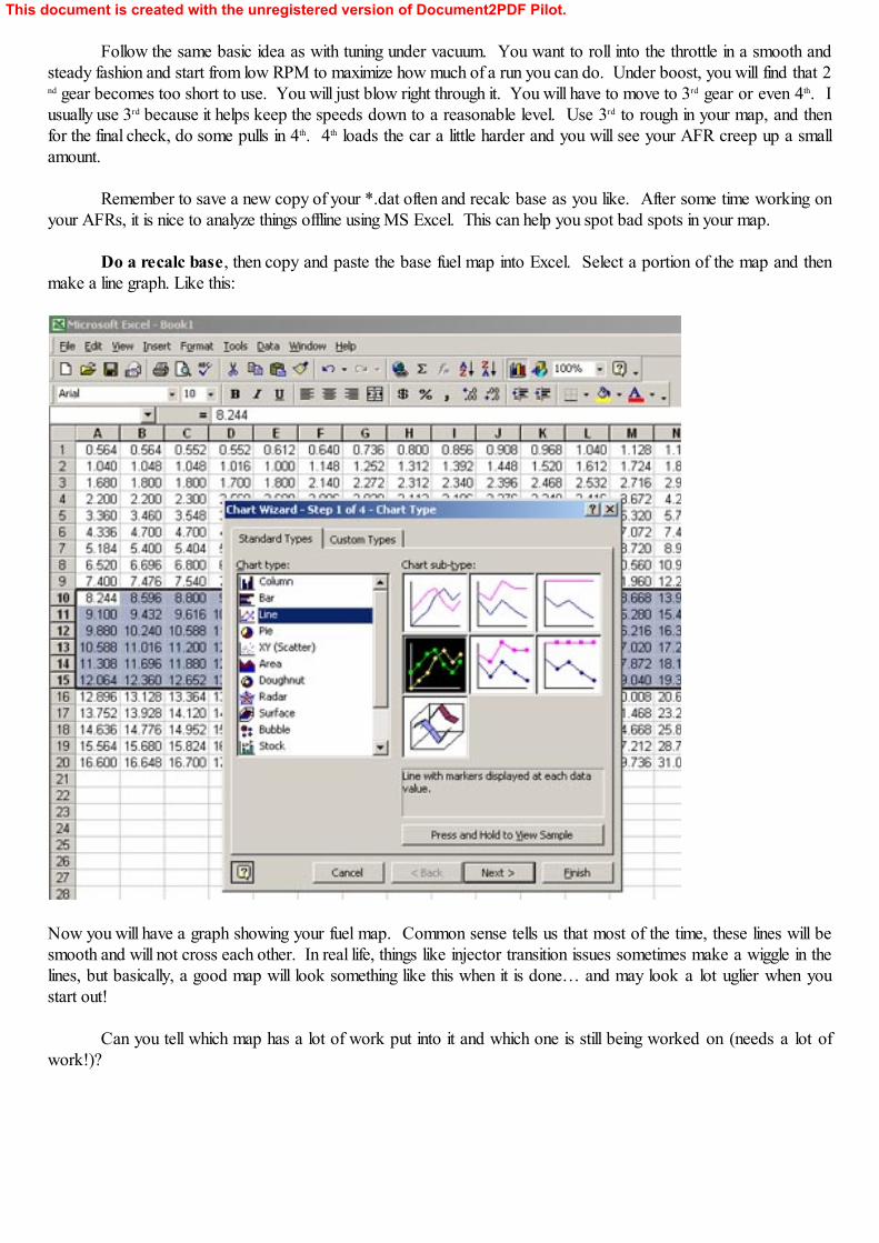
Follow the same basic idea as with tuning under vacuum. You want to roll into the throttle in a smooth andsteady fashion and start from low RPM to maximize how much of a run you can do. Under boost, you will find that 2nd gear becomes too short to use. You will just blow right through it. You will have to move to 3rd gear or even 4th. Iusually use 3rd because it helps keep the speeds down to a reasonable level. Use 3rd to rough in your map, and thenfor the final check, do some pulls in 4th. 4th loads the car a little harder and you will see your AFR creep up a smallamount.
Remember to save a new copy of your *.dat often and recalc base as you like. After some time working onyour AFRs, it is nice to analyze things offline using MS Excel. This can help you spot bad spots in your map.
Do a recalc base, then copy and paste the base fuel map into Excel. Select a portion of the map and thenmake a line graph. Like this:
Now you will have a graph showing your fuel map. Common sense tells us that most of the time, these lines will besmooth and will not cross each other. In real life, things like injector transition issues sometimes make a wiggle in thelines, but basically, a good map will look something like this when it is done… and may look a lot uglier when youstart out!
Can you tell which map has a lot of work put into it and which one is still being worked on (needs a lot ofwork!)?
This document is created with the unregistered version of Document2PDF Pilot.
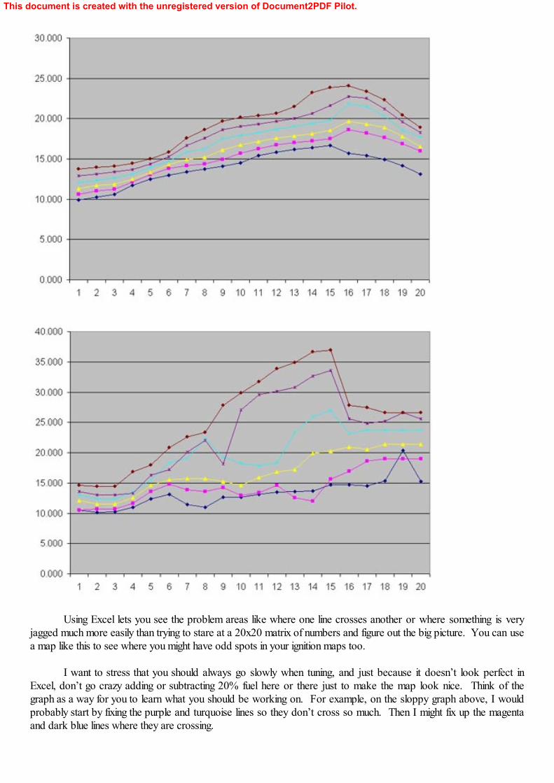
Using Excel lets you see the problem areas like where one line crosses another or where something is veryjagged much more easily than trying to stare at a 20x20 matrix of numbers and figure out the big picture. You can usea map like this to see where you might have odd spots in your ignition maps too.
I want to stress that you should always go slowly when tuning, and just because it doesn’t look perfect inExcel, don’t go crazy adding or subtracting 20% fuel here or there just to make the map look nice. Think of thegraph as a way for you to learn what you should be working on. For example, on the sloppy graph above, I wouldprobably start by fixing the purple and turquoise lines so they don’t cross so much. Then I might fix up the magentaand dark blue lines where they are crossing.
This document is created with the unregistered version of Document2PDF Pilot.
After you get your AFRs set up nice and safely and smoothly everywhere, you can hit the dyno and see whatyou lay down. The dyno is a good place to see the effects of timing changes. You can try advancing your timing (anddon’t forget to fix your split) about 2-3 degrees at a time. Watch your knock values. If they start going up, be extraextra careful. Do not just keep going up on timing just because your knock stays low; that can be a bad idea too. Iwould not exceed 15 deg timing at 15 PSI on pump fuel on a street ported motor. Bridge ports will probably be evenlower numbers than that, but I have zero experience tuning a bridge port, so I don’t know for sure. Timingadjustment can really make that dyno curve look great, or it can quickly blow an engine. I urge you to use the utmostcaution while adjusting timing.
Using all the information in this document should help you get started tuning your car. Always go slowly. Read everything twice. Only make changes when you understand what the anticipated effects are. Always watch forhigh AFRs, high injector duties, and high knock values. Check the online forums for help if you need it, there are a lotof good people on there willing to help you out. If you are still going to work with a professional tuner, I hope you atleast feel a little more familiar with what they’ll be doing after reading all this stuff.
6. References: In no particular order:
RX-7 Forum – http://www.rx7club.com/NoPistons Forum – http://www.nopistons.com/Tech Edge - http://www.techedge.com.au/Datalogit - http://www.fc-datalogit.co.nz/ FC-Edit FD3S Yahoo Group - http://sports.groups.yahoo.com/group/Datalogit-FD3S/My webpage – http://www.zeroglabs.com/
This document is created with the unregistered version of Document2PDF Pilot.


![Modelo 7s[1]](https://img.pdfslide.net/doc/110x75/55744cb0d8b42a0c468b4661/modelo-7s1.jpg)