Embed Size (px)
Citation preview
CI/SfB | | Rf7 | |
DRYWALL MANUAL

This document is intended as guidance for the correct use of Siniat GTEC products and systems in typical, best practice applications. It incorporates detailed technical information to assist the user in selecting and specifying the correct systems for the intended applications. This document does not cover all possible configurations of products in all possible constructions. When project requirements are different from the typical construction solutions shown then consultation with Siniat Specification Managers, Technical Enquiryline or other suitably qualified professionals should be sought.
There are references within this document to products to be supplied by other manufacturers; their advice should be sought when using their products. The fixing of GTEC products to various structures is beyond the scope of this document and advice should be sought from fixing suppliers and/or qualified professionals.
This document is non-exhaustive and provides general advice in line with good practice; further information should be sought when required. This document supersedes all previous guidance. All reasonable efforts have been made to ensure accuracy and future changes
and improvements may be made to the document without prejudice or notice. The correct installation and specification of GTEC systems and components is the responsibility of the contractor and the specifier. All GTEC systems should be constructed in accordance with all relevant building regulations and the guidance in ‘BS 8212:1995 Code of Practice for Dry lining and Partitioning using Gypsum Plasterboard’, ‘BS 8000-8:1994 Workmanship on building sites -Code of practice for plasterboard partitions and dry linings’ and ‘BS EN 13964:2004+A1:2006 Suspended ceilings – requirements and test methods’.
GTEC is registered trademark of Siniat Limited
© 2012 Siniat Limited
Call the Technical Enquiryline for technical advice and details specific to your project
01275 377 789
INNOVATIVE DRYLINING SOLUTIONS
Welcome to the new look Siniat Drywall Manual – a comprehensive guide
containing all the technical information you need to specify the best and
most appropriate drywall, drylining product or system. From enabling you to
design warm and safe residential environments, to guiding you to meeting and
exceeding regulations for the most demanding of commercial and industrial
installations, Siniat is confident you will find the best solution to match your
particular requirement.
INTRODUCTION 2
CONSIDER... SYSTEMS FOR HEALTHCARE
SYSTEMS FOR EDUCATION
SYSTEMS FOR RESIDENTIAL
INVENTED BY SINIAT
SYSTEM PERFORMANCE
6 8
1012 16
SPECIFY... GTEC® PARTITIONS 20
GTEC® FLOORS AND CEILINGS 120
GTEC® LININGS 178
GTEC® FIRE PROTECTION 242
GTEC® FINISHING 276
REFER... Product Reference 292
Profile Guide 332
Screw Selection Guide 334
Sustainability 336
Health and Safety 341
Standards 342
Index 344
The latest version of this publication can be found at www.siniat.co.uk/drywallmanual

2 INTRODUCTION
BUILDING ON SOLID FOUNDATIONSOur company was established in the UK in 1987
with a manufacturing facility on the outskirts of
Bristol – one of the most technically advanced
drywall production units in the world. It has
the capacity to produce and supply more than
50 million square metres of plasterboard a year.
A second plant at Ferrybridge opened in 2007,
enabling a 50% increase in UK manufacturing
capacity. Excellence is achieved through
continual investment in technology combined
with high quality materials. Fully automated plant
and high purity gypsum combine to produce
plasterboard products of the highest quality.
Siniat is a European leader in plasterboard
manufacture and systems, active across Europe
with major operations in France, Germany,
Benelux, Italy, Romania and Ukraine. The
worldwide head office located in Avignon,
France, also houses the Technical Development
Centre which has led the way in gypsum research
and product innovation. Siniat joined Etex,
a leading worldwide industrial and building
materials group, in 2011.
OUR COMMITMENT TO SUSTAINABLE CONSTRUCTIONThe need for sustainable buildings, and the
sustainable products to build them, is increasingly
important for both the construction industry, the
occupants of our buildings, and to us. We reacted
early to this challenge, amassing a number of
sustainability firsts in the process. Having led the
way, we remain firmly committed to sustainability.
We will continue to examine our product’s whole
lifecycle, from source to disposal, always looking
for new ways to reduce the amount of natural
resources we use.
Plasterboard is fully recyclable –
with no loss in quality
GTEC Products and Systems are
BRE Green Guide A / A+ rated and
help collect sustainability code credits
Certified and managed sustainability:
Responsible Sourcing BES 6001,
ISO 9001 and ISO 14001
Full plasterboard site waste collection and
recycling from GTEC Wasteline Direct
The leading recycler of post-consumer
plasterboard waste in each of the last three years
For more information on our life cycle approach
please refer to pages 336-340.
SHAPING THE WAY PEOPLE BUILD
3
ENQUIRYLINE T: 01275 377789 E: [email protected] www.siniat.co.uk
INTRODUCTION
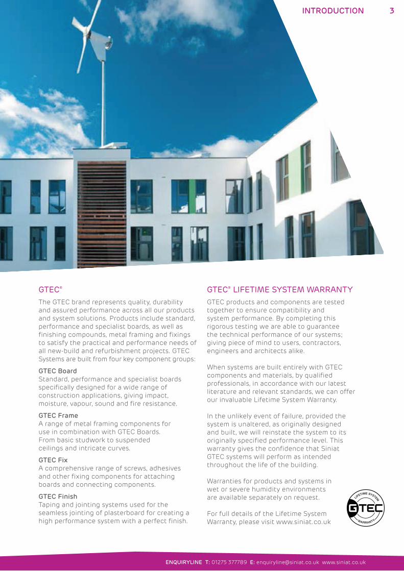
GTEC®
The GTEC brand represents quality, durability
and assured performance across all our products
and system solutions. Products include standard,
performance and specialist boards, as well as
finishing compounds, metal framing and fixings
to satisfy the practical and performance needs of
all new-build and refurbishment projects. GTEC
Systems are built from four key component groups:
GTEC Board
Standard, performance and specialist boards
specifically designed for a wide range of
construction applications, giving impact,
moisture, vapour, sound and fire resistance.
GTEC Frame
A range of metal framing components for
use in combination with GTEC Boards.
From basic studwork to suspended
ceilings and intricate curves.
GTEC Fix
A comprehensive range of screws, adhesives
and other fixing components for attaching
boards and connecting components.
GTEC Finish
Taping and jointing systems used for the
seamless jointing of plasterboard for creating a
high performance system with a perfect finish.
GTEC® LIFETIME SYSTEM WARRANTYGTEC products and components are tested
together to ensure compatibility and
system performance. By completing this
rigorous testing we are able to guarantee
the technical performance of our systems;
giving piece of mind to users, contractors,
engineers and architects alike.
When systems are built entirely with GTEC
components and materials, by qualified
professionals, in accordance with our latest
literature and relevant standards, we can offer
our invaluable Lifetime System Warranty.
In the unlikely event of failure, provided the
system is unaltered, as originally designed
and built, we will reinstate the system to its
originally specified performance level. This
warranty gives the confidence that Siniat
GTEC systems will perform as intended
throughout the life of the building.
Warranties for products and systems in
wet or severe humidity environments
are available separately on request.
For full details of the Lifetime System
Warranty, please visit www.siniat.co.uk
4 GTEC® SINIAT
RE-SHAPING THE SPECIFICATION PROCESS
5GTEC® SINIAT
ENQUIRYLINE T: 01275 377789 E: [email protected] www.siniat.co.uk
DEDICATED SUPPORT SERVICES TO THE SPECIFIERWhilst our suite of literature covers most typical
uses and situations, we understand that every
installation is different and there are bound to be
situations that are not covered. For this reason,
Siniat offers specification customers a range of
dedicated support services.
Our field based specification managers are
able to help with design, system selection,
construction details and project specifications.
Highly experienced they can develop solutions
to improve speed of installation, fire, sound and
thermal performance, as well as guiding you
through sector-specific requirements.
The dedicated Technical Enquiryline offer an
immediate response to your technical queries
including installation advice, product guidance,
and acoustic and U-value calculations.
We also provide a purpose-designed training
centre, which has been accredited by the CITB
and provides instruction in drywall installation
and management for contractors, merchants
and housebuilders.
Other support services include a series of
CPD seminars to keep our specifier customers
updated on the latest developments and
regulations. Siniat also subscribes to NBS Plus
and continues to invest in new technology to
improve the specification process.
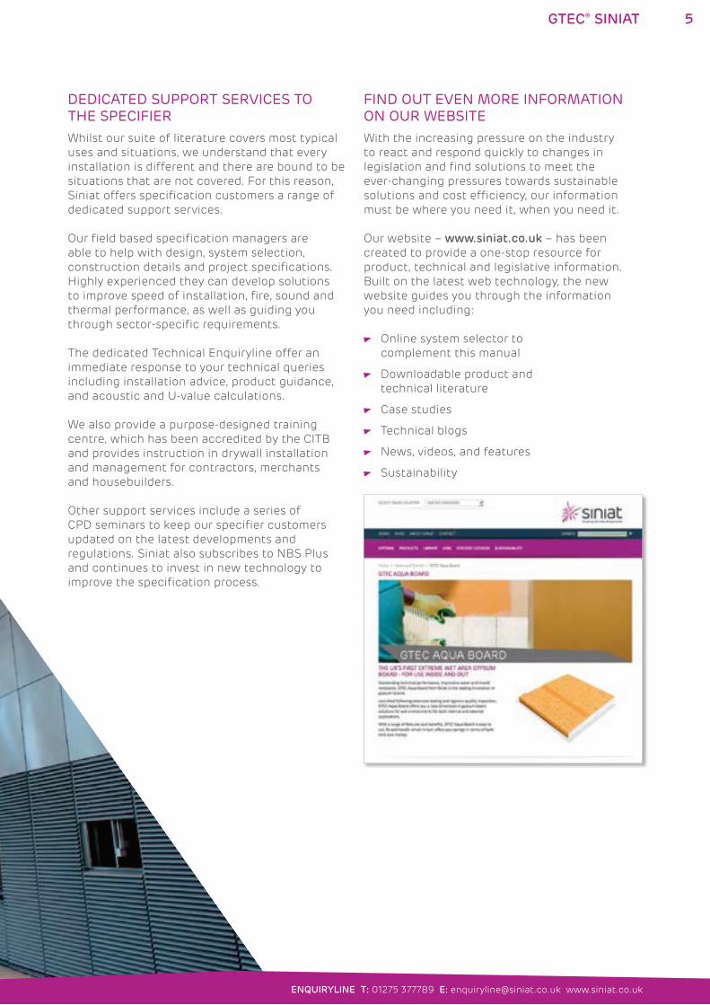
FIND OUT EVEN MORE INFORMATION ON OUR WEBSITEWith the increasing pressure on the industry
to react and respond quickly to changes in
legislation and find solutions to meet the
ever-changing pressures towards sustainable
solutions and cost efficiency, our information
must be where you need it, when you need it.
Our website – www.siniat.co.uk – has been
created to provide a one-stop resource for
product, technical and legislative information.
Built on the latest web technology, the new
website guides you through the information
you need including:
Online system selector to
complement this manual
Downloadable product and
technical literature
Case studies
Technical blogs
News, videos, and features
Sustainability
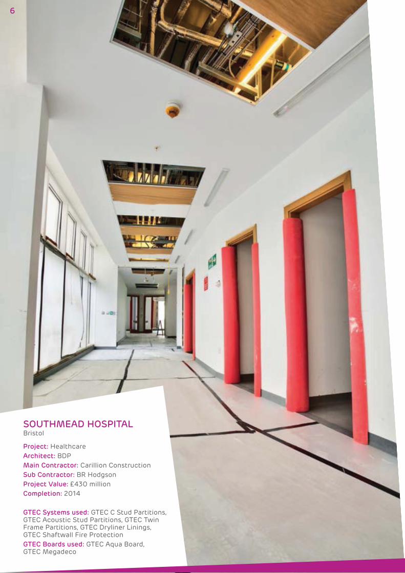
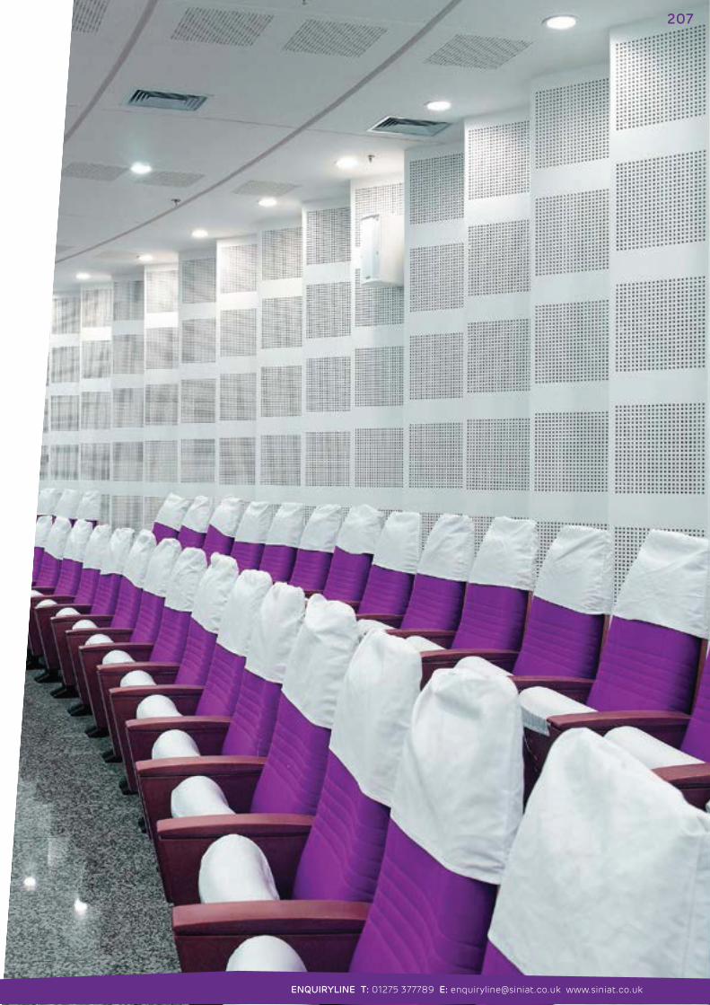
SOUTHMEAD HOSPITAL Bristol
Project: HealthcareArchitect: BDPMain Contractor: Carillion ConstructionSub Contractor: BR HodgsonProject Value: £430 millionCompletion: 2014
GTEC Systems used: GTEC C Stud Partitions, GTEC Acoustic Stud Partitions, GTEC Twin Frame Partitions, GTEC Dryliner Linings, GTEC Shaftwall Fire ProtectionGTEC Boards used: GTEC Aqua Board, GTEC Megadeco
6

SYSTEMS FOR HEALTHCAREGTEC Plasterboard Systems have been used extensively in major
healthcare projects across the UK and Ireland as fast and effective
solutions to healthcare construction.
The GTEC Boards and GTEC Systems have been developed to meet
and exceed the full range of extraordinary demands placed on
hospital and healthcare buildings.
EXTRAORDINARY DEMANDS
ACOUSTICS: The acoustic demands on partitions in Healthcare buildings are extreme; from ensuring consultation room privacy and operation suite concentration, to dealing with emergency vehicle sirens and the intensity of A&E departments.
While layout can ease noise risk, GTEC Systems allow for flexible design with extremely high levels of sound insulation from space to space. The partition performance ensures that a superior healing environment is achieved. GTEC Pregybel ceilings also help to control noise levels through acoustic absorption.
FIRE: Multi-storey constructions containing bed-bound patients, large public areas, multiple service entrances and numerous circulation routes, place a high fire resistance demand on any project.
GTEC Partitions and GTEC Ceilings provide a simple design with high levels of fire resistance and robust detailing for design flexibility. GTEC Shaftwall and GTEC Encasement Fire Protection solutions offer specialist passive fire protection to lifts, shafts and structural steel.
IMPACT: Hospitals are dynamic, highly trafficked, public environments where walls are subject to constant impact from staff, visitors and hospital equipment.
GTEC LaDura, a unique and exceptionally strong plasterboard, achieves severe duty ratings with the minimum of boarding. Plus, it provides high levels of fixing resistance for crash rails, skirting, services and fixtures.
HYGIENE: Easy to clean surfaces are vital for good healthcare environments which need frequent washing, and are dependent on excellent hygiene.
GTEC Finishing solutions combined with GTEC Partition and Lining systems offer smooth, easy to joint and repairable surfaces which are easier to clean. GTEC Megadeco Board requires no pre-sealing for even faster finishing.
KEY GUIDANCE DOCUMENTS AND REGULATIONS:
NHS Guidance:
Acoustics: Technical Design Manual
Firecode HTM 05
BREEAM New Construction:
Healthcare
Building Regulations:
Approved Document Part B 2006 – Fire Safety
7
ENQUIRYLINE T: 01275 377789 E: [email protected] www.siniat.co.uk
GTEC® SYSTEMS FOR HEALTHCARE
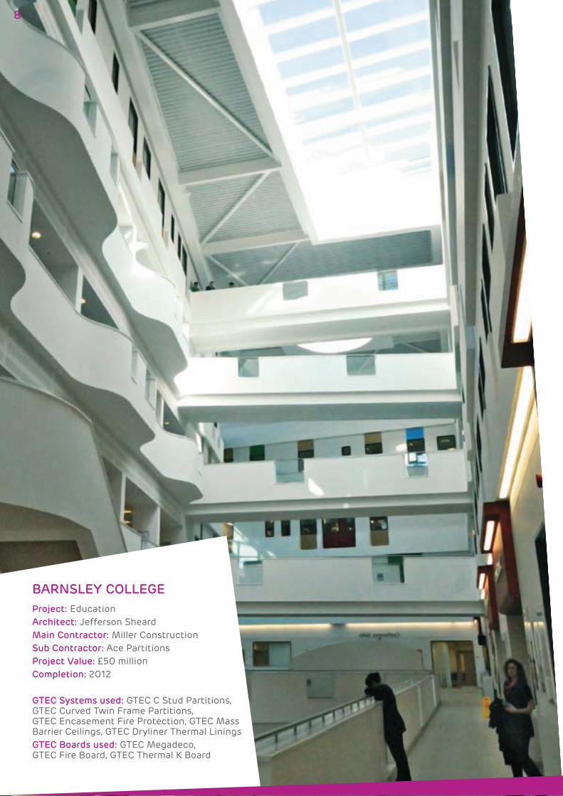
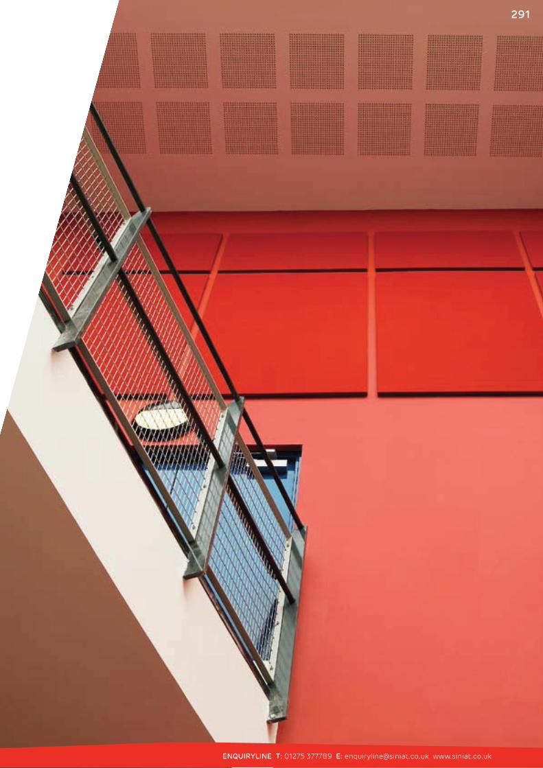
BARNSLEY COLLEGE
Project: EducationArchitect: Jefferson SheardMain Contractor: Miller ConstructionSub Contractor: Ace PartitionsProject Value: £50 millionCompletion: 2012
GTEC Systems used: GTEC C Stud Partitions, GTEC Curved Twin Frame Partitions, GTEC Encasement Fire Protection, GTEC Mass Barrier Ceilings, GTEC Dryliner Thermal LiningsGTEC Boards used: GTEC Megadeco, GTEC Fire Board, GTEC Thermal K Board
8
SYSTEMS FOR EDUCATIONGTEC Plasterboard Systems have been adopted in hundreds of
school, academy, college and university projects across the UK and
Ireland to efficiently meet the needs of education construction.
The range of GTEC Board and GTEC Systems suit the full scope
of extraordinary demands placed on education buildings.
KEY GUIDANCE DOCUMENTS AND REGULATIONS:
Department for Education Guidance:
BB93 – Acoustic Design in Schools
BB100 – Design for Fire Safety in Schools
BREEAM New Construction:
Education
Building Regulations:
Approved Document Part E 2003 – Resistance to the
Passage of Sound
Approved Document Part B 2006 – Fire Safety
EXTRAORDINARY DEMANDS
ACOUSTICS: From music and sports noise to examination room silence, Education buildings place extreme acoustic demands on specification. The isolation and control of ambient noise from space to space is vital, as is good speech clarity in open spaces, along with controlled reverberation.
While layout design can reduce noise risk, GTEC Systems’ high level of sound insulation allows design flexibility from space to space. GTEC Pregybel ceilings offer acoustic absorption and echo control, improving speech clarity and reducing noise distractions.
FIRE: “Each year around 1 in 20 schools experiences a fire and nearly 60% of school
fires are started deliberately.” BB100
Large circulation areas, multi-storey construction and broad types of use from science labs to sports halls place a high fire resistance need on any Education project.
GTEC Partitions and GTEC Ceilings achieve high levels of fire resistance with uncomplicated, robust and proven detailing for design flexibility. GTEC Shaftwall and GTEC Encasement Fire Protection solutions offer specialist passive fire protection to lifts, shafts and structural steel.
IMPACT: Education buildings face some of the most intense usage. With high levels of student movement, a wide variety of activities taking place and the chance of misuse, careful specification is needed to reduce maintenance and repairs.
GTEC LaDura Board is exceptionally strong and achieves severe duty ratings with the minimum of boarding. It offers excellent impact performance for corridors and high levels of fixing resistance for fixtures and fittings.
DESIGN: An innovative design can transform the learning experience of students, enhancing their performance, motivation, behaviour and engagement.
Ideal for the most ambitious projects, GTEC Systems are flexible, high performance and easy to install, providing quick construction. GTEC LaDura, Aqua Board and Megadeco take plasterboard systems to new areas replacing slower, less flexible, wet construction methods.
9
ENQUIRYLINE T: 01275 377789 E: [email protected] www.siniat.co.uk
GTEC® SYSTEMS FOR EDUCATION
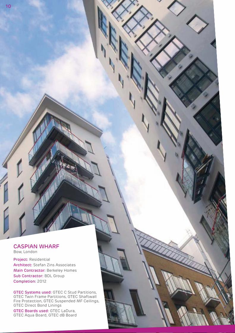
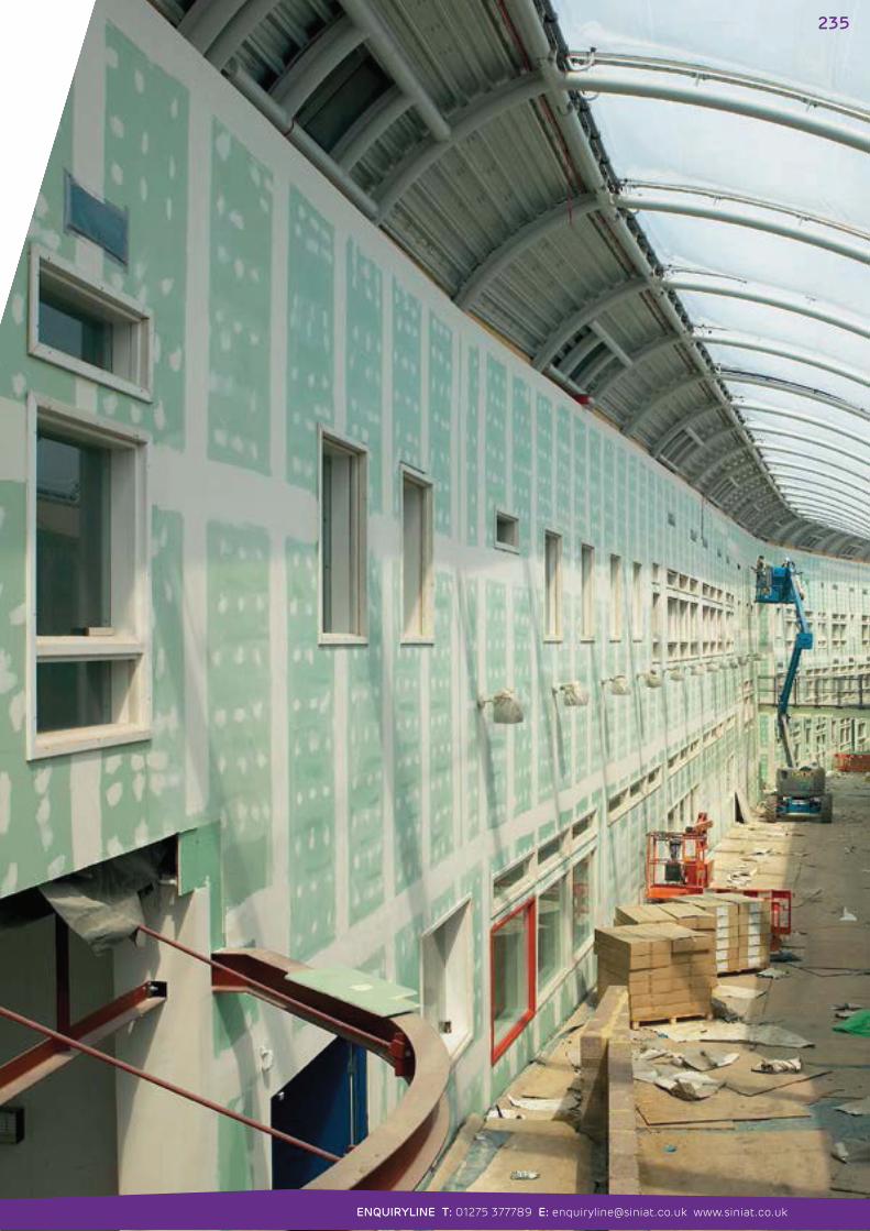
CASPIAN WHARF Bow, London
Project: ResidentialArchitect: Stefan Zins AssociatesMain Contractor: Berkeley HomesSub Contractor: BDL GroupCompletion: 2012
GTEC Systems used: GTEC C Stud Partitions, GTEC Twin Frame Partitions, GTEC Shaftwall Fire Protection, GTEC Suspended MF Ceilings, GTEC Direct Bond LiningsGTEC Boards used: GTEC LaDura, GTEC Aqua Board, GTEC dB Board
10
SYSTEMS FOR RESIDENTIALGTEC Plasterboard Systems have been used across the UK and
Ireland to successfully build or renovate thousands of housing,
apartment and hotel projects.
The diverse range of GTEC Board and GTEC Systems features solutions
ideal for the construction of homes and other residential buildings.
EXTRAORDINARY DEMANDS
ACOUSTICS: Busy lifestyles, close neighbours and urban noise can all combine to affect the quality of home life. Party walls, party floors, partitions and ceilings all require special attention to reduce noise issues.
GTEC Systems are tested to achieve extremely high levels of sound insulation. They meet Part E Regulations and the enhanced CSH (Code for Sustainable Homes) requirements* with the minimum of components.
*+3dB and +5dB over Part E for separating elements (Code for Sustainable Homes Technical Guide – November 2010)
FIRE: With occupants of all ages, most often present at night while asleep, a fire resistant design is essential. Multi-storey buildings and their escape routes present even greater fire resistance needs, as stipulated by Building Regulations Part B – Fire Safety.
GTEC Partitions and GTEC Ceilings achieve a full range of fire resistance using minimal components for multi-storey apartments, dense housing developments and detached houses. Robust and proven detailing enables design flexibility and economic construction.
SUSTAINABILITY: Dwellings are responsible for up to 30% of national carbon emissions through their construction and use. Huge changes to the Building Regulations, as well as the Code for Sustainable Homes (CSH), have been implemented to reduce these carbon emissions representing a major shift in construction methods.
The use of GTEC Systems can earn CSH credits in a variety of ways – for more details see the Sustainability section on pages 336-340. GTEC Systems are made up of fully recyclable components with gypsum plasterboard being 100% re-usable in a closed loop process. Recent product innovations use minimal components to achieve technical performances, limiting material usage and waste.
All GTEC Lining systems can provide insulation to enhance the thermal performance of external walls. These include the GTEC Thermal Boards range; thermally laminated plasterboards which are recommended by Approved Document L1B to achieve thermal upgrades in renovation projects.
KEY GUIDANCE DOCUMENTS AND REGULATIONS:
Code for Sustainable Homes
Building Regulations:
Approved Document Part E 2003 – Resistance to the
Passage of Sound
Approved Document Part B 2006 – Fire Safety
Approved Document Part L1 A&B 2010 – Conservation of
Fuel and Power
11
ENQUIRYLINE T: 01275 377789 E: [email protected] www.siniat.co.uk
GTEC® SYSTEMS FOR RESIDENTIAL
INVENTED BY SINIAT
OUR UNIQUE BOARDS
From over 25 years of experience on building sites we know
there is unmet potential in drywall and have created the
boards to unlock it.
Excellent fire and acoustic performance is always
expected and we have the range of boards with
higher densities, highly developed additives and
patented technology to achieve the top levels
of fire and sound performance needed in the UK
and Ireland.
But we don’t consider that to be enough. Better
finishing capabilities are available. As a result we
are the first and only manufacturers of gypsum
plasterboards which offer exceptional water
resistance, exceptional strength and exceptional
finishing speed.
We also know that one board can do more than
one thing. Our boards combine the highest levels
of performance making them suitable for a huge
breadth of applications, reducing the amount
of fixing, and potentially meaning only a single
board type is needed on site.
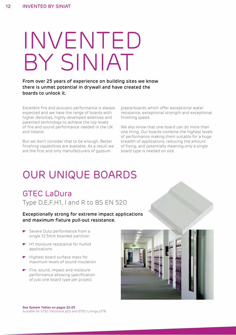
Exceptionally strong for extreme impact applications
and maximum fixture pull-out resistance.
See System Tables on pages 22-25 Suitable for GTEC Partitions p20 and GTEC Linings p178
GTEC LaDuraType D,E,F,H1, I and R to BS EN 520
Severe Duty performance from a
single 12.5mm boarded partition
H1 moisture resistance for humid
applications
Highest board surface mass for
maximum levels of sound insulation
Fire, sound, impact and moisture
performance allowing specification
of just one board type per project
12 INVENTED BY SINIAT
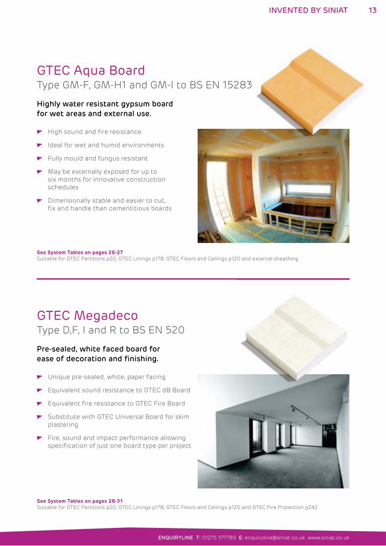
Pre-sealed, white faced board for
ease of decoration and finishing.
See System Tables on pages 28-31 Suitable for GTEC Partitions p20, GTEC Linings p178, GTEC Floors and Ceilings p120 and GTEC Fire Protection p242
GTEC MegadecoType D,F, I and R to BS EN 520
Unique pre-sealed, white, paper facing
Equivalent sound resistance to GTEC dB Board
Equivalent fire resistance to GTEC Fire Board
Substitute with GTEC Universal Board for skim
plastering
Fire, sound and impact performance allowing
specification of just one board type per project
Highly water resistant gypsum board
for wet areas and external use.
See System Tables on pages 26-27 Suitable for GTEC Partitions p20, GTEC Linings p178, GTEC Floors and Ceilings p120 and external sheathing
GTEC Aqua BoardType GM-F, GM-H1 and GM-I to BS EN 15283
High sound and fire resistance
Ideal for wet and humid environments
Fully mould and fungus resistant
May be externally exposed for up to
six months for innovative construction
schedules
Dimensionally stable and easier to cut,
fix and handle than cementitious boards
13
ENQUIRYLINE T: 01275 377789 E: [email protected] www.siniat.co.uk
INVENTED BY SINIAT
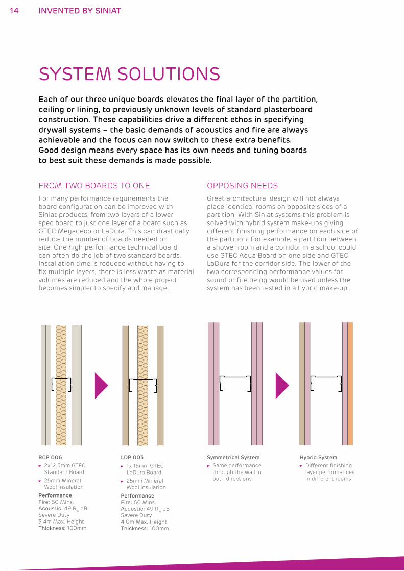
Symmetrical System
Same performance
through the wall in
both directions
RCP 006
2x12.5mm GTEC
Standard Board
25mm Mineral
Wool Insulation
Performance
Fire: 60 Mins.
Acoustic: 49 Rw dB
Severe Duty
3.4m Max. Height
Thickness: 100mm
LDP 003
1x 15mm GTEC
LaDura Board
25mm Mineral
Wool Insulation
Performance
Fire: 60 Mins.
Acoustic: 49 Rw dB
Severe Duty
4.0m Max. Height
Thickness: 100mm
Hybrid System
Different finishing
layer performances
in different rooms
SYSTEM SOLUTIONSEach of our three unique boards elevates the final layer of the partition,
ceiling or lining, to previously unknown levels of standard plasterboard
construction. These capabilities drive a different ethos in specifying
drywall systems – the basic demands of acoustics and fire are always
achievable and the focus can now switch to these extra benefits.
Good design means every space has its own needs and tuning boards
to best suit these demands is made possible.
FROM TWO BOARDS TO ONE OPPOSING NEEDS
For many performance requirements the
board configuration can be improved with
Siniat products, from two layers of a lower
spec board to just one layer of a board such as
GTEC Megadeco or LaDura. This can drastically
reduce the number of boards needed on
site. One high performance technical board
can often do the job of two standard boards.
Installation time is reduced without having to
fix multiple layers, there is less waste as material
volumes are reduced and the whole project
becomes simpler to specify and manage.
Great architectural design will not always
place identical rooms on opposite sides of a
partition. With Siniat systems this problem is
solved with hybrid system make-ups giving
different finishing performance on each side of
the partition. For example, a partition between
a shower room and a corridor in a school could
use GTEC Aqua Board on one side and GTEC
LaDura for the corridor side. The lower of the
two corresponding performance values for
sound or fire being would be used unless the
system has been tested in a hybrid make-up.
14 INVENTED BY SINIAT
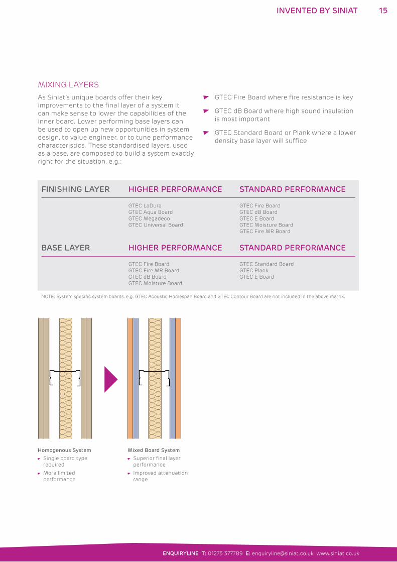
FINISHING LAYER HIGHER PERFORMANCE STANDARD PERFORMANCE
GTEC LaDura
GTEC Aqua Board
GTEC Megadeco
GTEC Universal Board
GTEC Fire Board
GTEC dB Board
GTEC E Board
GTEC Moisture Board
GTEC Fire MR Board
BASE LAYER HIGHER PERFORMANCE STANDARD PERFORMANCE
GTEC Fire Board
GTEC Fire MR Board
GTEC dB Board
GTEC Moisture Board
GTEC Standard Board
GTEC Plank
GTEC E Board
NOTE: System specific system boards, e.g. GTEC Acoustic Homespan Board and GTEC Contour Board are not included in the above matrix.
Mixed Board System
Superior final layer
performance
Improved attenuation
range
Homogenous System
Single board type
required
More limited
performance
MIXING LAYERS
As Siniat’s unique boards offer their key
improvements to the final layer of a system it
can make sense to lower the capabilities of the
inner board. Lower performing base layers can
be used to open up new opportunities in system
design, to value engineer, or to tune performance
characteristics. These standardised layers, used
as a base, are composed to build a system exactly
right for the situation, e.g.:
GTEC Fire Board where fire resistance is key
GTEC dB Board where high sound insulation
is most important
GTEC Standard Board or Plank where a lower
density base layer will suffice
15
ENQUIRYLINE T: 01275 377789 E: [email protected] www.siniat.co.uk
INVENTED BY SINIAT
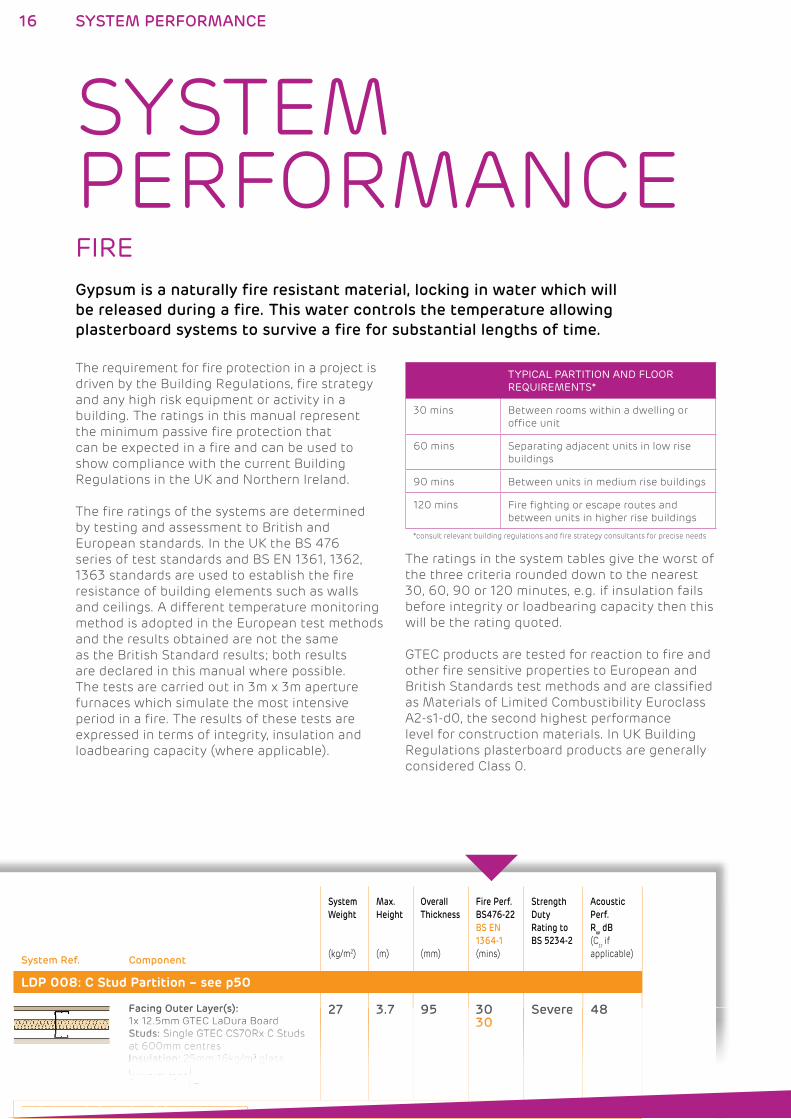
SYSTEM PERFORMANCEFIREGypsum is a naturally fire resistant material, locking in water which will
be released during a fire. This water controls the temperature allowing
plasterboard systems to survive a fire for substantial lengths of time.
The requirement for fire protection in a project is
driven by the Building Regulations, fire strategy
and any high risk equipment or activity in a
building. The ratings in this manual represent
the minimum passive fire protection that
can be expected in a fire and can be used to
show compliance with the current Building
Regulations in the UK and Northern Ireland.
The fire ratings of the systems are determined
by testing and assessment to British and
European standards. In the UK the BS 476
series of test standards and BS EN 1361, 1362,
1363 standards are used to establish the fire
resistance of building elements such as walls
and ceilings. A different temperature monitoring
method is adopted in the European test methods
and the results obtained are not the same
as the British Standard results; both results
are declared in this manual where possible.
The tests are carried out in 3m x 3m aperture
furnaces which simulate the most intensive
period in a fire. The results of these tests are
expressed in terms of integrity, insulation and
loadbearing capacity (where applicable).
The ratings in the system tables give the worst of
the three criteria rounded down to the nearest
30, 60, 90 or 120 minutes, e.g. if insulation fails
before integrity or loadbearing capacity then this
will be the rating quoted.
GTEC products are tested for reaction to fire and
other fire sensitive properties to European and
British Standards test methods and are classified
as Materials of Limited Combustibility Euroclass
A2-s1-d0, the second highest performance
level for construction materials. In UK Building
Regulations plasterboard products are generally
considered Class 0.
System Ref. Component
System
Weight
(kg/m2)
Max.
Height
(m)
Overall
Thickness
(mm)
Fire Perf.
BS476-22
BS EN
1364-1
(mins)
Strength
Duty
Rating to
BS 5234-2
Acoustic
Perf.
Rw dB
(Ctr if
applicable)
LDP 008: C Stud Partition – see p50
Facing Outer Layer(s):
1x 12.5mm GTEC LaDura Board
Studs: Single GTEC CS70Rx C Studs
at 600mm centres
Insulation: 25mm 16kg/m3 glass
mineral wool
Accessories: –
27 3.7 95 3030
Severe 48
LDP 001: C Stud Partition – see p50
Facing Outer Layer(s):
1x1x1x1x1x1x 12121212.12.12.5mm5mm5mm5mm5mm5mm GTGTGTGTGT GTECECECECECEC LaDLaDLaDLaDLaDLaDuraurauraurauraura BoBoBoBoBo Boardardardardardard
StuStuStuStuStuStuStuds:ds:ds:ds:ds:ds:ds: SinSinSinSinSinSinSingleglegleglegleglegle GTGTGTGTGTGT GTECECECECECECEC CS7CS7CS7CS7CS7CS7CS70Rx0Rx0Rx0Rx0Rx0Rx0Rx CCCCCC C StuStuStuStuStuStuStudsdsdsdsdsdsds
tatatatat 600600600600600mmmmmmmm cencencencenttretretretressss
IIInsInsInsIns llulaulaulaula ititiotiotiotion:n:n:n: 22525m25m25m25m 11m 1m 1m 1m 16k6k6kg6kg6kg6kg///m/m/m/m3333 llglglgl glassassassass
mineral wool
Accessories: –
27 3.7 95 3030303030
Severe 48
LDP 001: C Stud Partition – see p50
16 SYSTEM PERFORMANCE
TYPICAL PARTITION AND FLOOR REQUIREMENTS*
30 mins Between rooms within a dwelling or
office unit
60 mins Separating adjacent units in low rise
buildings
90 mins Between units in medium rise buildings
120 mins Fire fighting or escape routes and
between units in higher rise buildings
*consult relevant building regulations and fire strategy consultants for precise needs
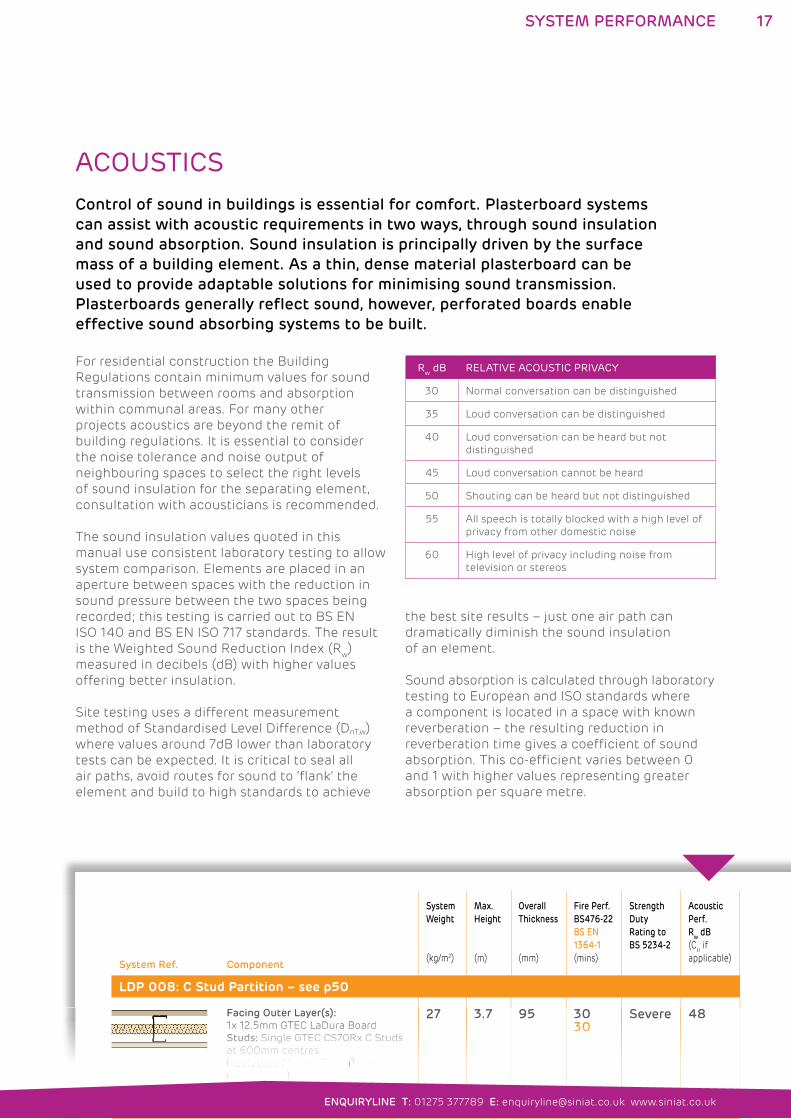
ACOUSTICS Control of sound in buildings is essential for comfort. Plasterboard systems
can assist with acoustic requirements in two ways, through sound insulation
and sound absorption. Sound insulation is principally driven by the surface
mass of a building element. As a thin, dense material plasterboard can be
used to provide adaptable solutions for minimising sound transmission.
Plasterboards generally reflect sound, however, perforated boards enable
effective sound absorbing systems to be built.
For residential construction the Building
Regulations contain minimum values for sound
transmission between rooms and absorption
within communal areas. For many other
projects acoustics are beyond the remit of
building regulations. It is essential to consider
the noise tolerance and noise output of
neighbouring spaces to select the right levels
of sound insulation for the separating element,
consultation with acousticians is recommended.
The sound insulation values quoted in this
manual use consistent laboratory testing to allow
system comparison. Elements are placed in an
aperture between spaces with the reduction in
sound pressure between the two spaces being
recorded; this testing is carried out to BS EN
ISO 140 and BS EN ISO 717 standards. The result
is the Weighted Sound Reduction Index (Rw)
measured in decibels (dB) with higher values
offering better insulation.
Site testing uses a different measurement
method of Standardised Level Difference (DnT,w)
where values around 7dB lower than laboratory
tests can be expected. It is critical to seal all
air paths, avoid routes for sound to ‘flank’ the
element and build to high standards to achieve
the best site results – just one air path can
dramatically diminish the sound insulation
of an element.
Sound absorption is calculated through laboratory
testing to European and ISO standards where
a component is located in a space with known
reverberation – the resulting reduction in
reverberation time gives a coefficient of sound
absorption. This co-efficient varies between 0
and 1 with higher values representing greater
absorption per square metre.
System Ref. Component
System
Weight
(kg/m2)
Max.
Height
(m)
Overall
Thickness
(mm)
Fire Perf.
BS476-22
BS EN
1364-1
(mins)
Strength
Duty
Rating to
BS 5234-2
Acoustic
Perf.
Rw dB
(Ctr if
applicable)
LDP 008: C Stud Partition – see p50
Facing Outer Layer(s):
1x 12.5mm GTEC LaDura Board
Studs: Single GTEC CS70Rx C Studs
at 600mm centres
Insulation: 25mm 16kg/m3 glass
mineral wool
Accessories: –
27 3.7 95 3030
Severe 48
LDP 001: C Stud Partition – see p50
Facing Outer Layer(s):
11x1x1x1x1x1x1x1x 2121212121212.12.12.12.55mm5mm5mm5mm5mm5mm5mm5mm GTGTGTGTGTGTGTGT GTECECECECECECECECEC L DLaDLaDLaDLaDLaDLaDLaDLaDuraurauraurauraurauraura BBoBoBoBoBoBoBo Bo dardardardardardardardard
StStuStuStuStuStuStudsdsds:ds:ds:ds:ds: SiSinSinSinSinSinSin lglegleglegleglegleg GTGTGTGTGTGT GTECECECECECECEC CS7CS7CS7CS7CS7CS7CS70R0Rx0Rx0Rx0Rx0Rx0Rx CCCCCC C StStuStuStuStuStuStuddsdsdsdsdsds
tatatatat 600600600600600600mmmmmmmm cencencencenttretretretressss
IIns llula itition: 2525m 1m 16k6k6kg///m333 l glass
mineral wool
Accessories: –
27 3.7 95 30030303030303030
Severe 48
LDP 001: C Stud Partition – see p50
17
ENQUIRYLINE T: 01275 377789 E: [email protected] www.siniat.co.uk
SYSTEM PERFORMANCE
Rw dB RELATIVE ACOUSTIC PRIVACY
30 Normal conversation can be distinguished
35 Loud conversation can be distinguished
40 Loud conversation can be heard but not
distinguished
45 Loud conversation cannot be heard
50 Shouting can be heard but not distinguished
55 All speech is totally blocked with a high level of
privacy from other domestic noise
60 High level of privacy including noise from
television or stereos
System Ref. Component
System
Weight
(kg/m2)
Max.
Height
(m)
Overall
Thickness
(mm)
Fire Perf.
BS476-22
BS EN
1364-1
(mins)
Strength
Duty
Rating to
BS 5234-2
Acoustic
Perf.
Rw dB
(Ctr if
applicable)
LDP 008: C Stud Partition – see p50
Facing Outer Layer(s):
1x 12.5mm GTEC LaDura Board
Studs: Single GTEC CS70Rx C Studs
at 600mm centres
Insulation: 25mm 16kg/m3 glass
mineral wool
Accessories: –
27 3.7 95 3030
Severe 48
LDP 001: C Stud Partition – see p50
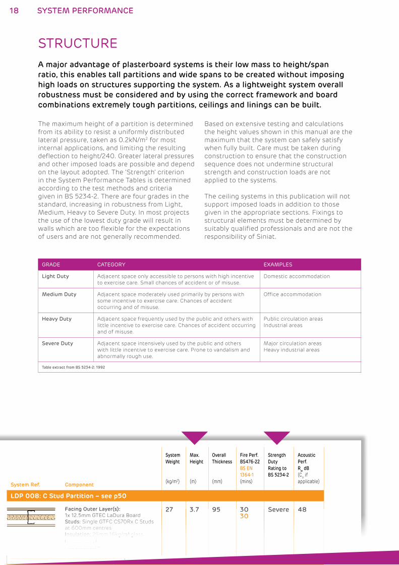
STRUCTURE A major advantage of plasterboard systems is their low mass to height/span
ratio, this enables tall partitions and wide spans to be created without imposing
high loads on structures supporting the system. As a lightweight system overall
robustness must be considered and by using the correct framework and board
combinations extremely tough partitions, ceilings and linings can be built.
The maximum height of a partition is determined
from its ability to resist a uniformly distributed
lateral pressure, taken as 0.2kN/m2 for most
internal applications, and limiting the resulting
deflection to height/240. Greater lateral pressures
and other imposed loads are possible and depend
on the layout adopted. The ‘Strength’ criterion
in the System Performance Tables is determined
according to the test methods and criteria
given in BS 5234-2. There are four grades in the
standard, increasing in robustness from Light,
Medium, Heavy to Severe Duty. In most projects
the use of the lowest duty grade will result in
walls which are too flexible for the expectations
of users and are not generally recommended.
Based on extensive testing and calculations
the height values shown in this manual are the
maximum that the system can safely satisfy
when fully built. Care must be taken during
construction to ensure that the construction
sequence does not undermine structural
strength and construction loads are not
applied to the systems.
The ceiling systems in this publication will not
support imposed loads in addition to those
given in the appropriate sections. Fixings to
structural elements must be determined by
suitably qualified professionals and are not the
responsibility of Siniat.
Facing Outer Layer(s):
1x1x1x1x1x1x 121212.12.12.12.5mm5mm5mm5mm5mm5mm GTGTGTGTGT GTECECECECECEC LaDLaDLaDLaDLaDLaDuraurauraurauraura BoBoBoBoBo Boardardardardardard
StuStuStuStuStuStuStuds:ds:ds:ds:ds:ds:ds: SinSinSinSinSinSinSingleglegleglegleglegle GTGTGTGTGT GTGTECECECECECEC C CS7CS7CS7CS7CS7CS7CS70Rx0Rx0Rx0Rx0Rx0Rx0Rx CCCCC C C StuStuStuStuStuStuStudsdsdsdsdsds ds
atatatatat 600600600600600mmmmmmmmmm cencencencencentretretretretresssss
IIInsInsInsIns llulaulaulaula ititiotiotiotion:n:n:n: 252525m25m25m25m 11m 1m 1m 1m 16k6k6kg6kg6kg6kg///m/m/m/m3333 llglglgl glassassassass
mineral wool
Accessories: –
27 3.7 95 3030303030
Severe 48
LDP 001: C Stud Partition – see p50
18 SYSTEM PERFORMANCE
GRADE CATEGORY EXAMPLES
Light Duty Adjacent space only accessible to persons with high incentive
to exercise care. Small chances of accident or of misuse.
Domestic accommodation
Medium Duty Adjacent space moderately used primarily by persons with
some incentive to exercise care. Chances of accident
occurring and of misuse.
Office accommodation
Heavy Duty Adjacent space frequently used by the public and others with
little incentive to exercise care. Chances of accident occurring
and of misuse.
Public circulation areas
Industrial areas
Severe Duty Adjacent space intensively used by the public and others
with little incentive to exercise care. Prone to vandalism and
abnormally rough use.
Major circulation areas
Heavy industrial areas
Table extract from BS 5234-2: 1992
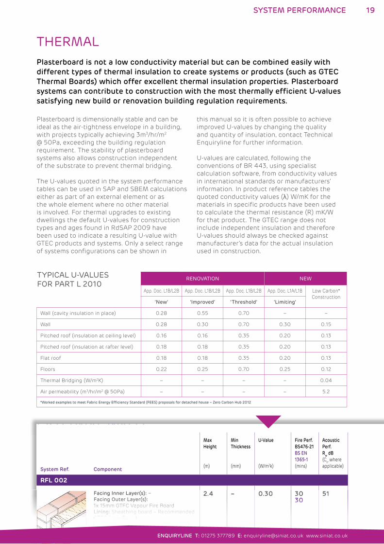
THERMALPlasterboard is not a low conductivity material but can be combined easily with
different types of thermal insulation to create systems or products (such as GTEC
Thermal Boards) which offer excellent thermal insulation properties. Plasterboard
systems can contribute to construction with the most thermally efficient U-values
satisfying new build or renovation building regulation requirements.
Plasterboard is dimensionally stable and can be
ideal as the air-tightness envelope in a building,
with projects typically achieving 3m3/hr/m2
@ 50Pa, exceeding the building regulation
requirement. The stability of plasterboard
systems also allows construction independent
of the substrate to prevent thermal bridging.
The U-values quoted in the system performance
tables can be used in SAP and SBEM calculations
either as part of an external element or as
the whole element where no other material
is involved. For thermal upgrades to existing
dwellings the default U-values for construction
types and ages found in RdSAP 2009 have
been used to indicate a resulting U-value with
GTEC products and systems. Only a select range
of systems configurations can be shown in
this manual so it is often possible to achieve
improved U-values by changing the quality
and quantity of insulation, contact Technical
Enquiryline for further information.
U-values are calculated, following the
conventions of BR 443, using specialist
calculation software, from conductivity values
in international standards or manufacturers’
information. In product reference tables the
quoted conductivity values (λ) W/mK for the
materials in specific products have been used
to calculate the thermal resistance (R) mK/W
for that product. The GTEC range does not
include independent insulation and therefore
U-values should always be checked against
manufacturer’s data for the actual insulation
used in construction.
System Ref. Component
Max
Height
(m)
Min
Thickness
(mm)
U-Value
(W/m2k)
Fire Perf.
BS476-21
BS EN
1365-1
(mins)
Acoustic
Perf.
Rw dB
(Ctr where
applicable)
RFL 002
Facing Inner Layer(s): –
Facing Outer Layer(s):
1x 15mm GTEC Vapour Fire Board
Lining: Sheathing board – Recommended
GTEC Aqua Board
Insulation: 120mm glass fibre (BS5250)
Internal Wall Leaf: Timber Frame Stud
work
External Wall Leaf: Brickwork
2.4 – 0.30 3030
51
EXTERNAL WALLS
Facing Inner Layer(s): –
FFFacFacFacFacFacFacFaciiinginginginginginginggg OOOuOuOuOuOuOu Outterterterterterterter LLLaLaLaLaLaLa Layeryeryeryeryeryeryeryy ( )( )( )(s)(s)(s)(s)(s)(s)(s)( )( )::::::
11x1x1x1x1x 1x 1515m15m15m15m15m15m Gm Gm Gm Gm Gm Gm GTECTECTECTECTECTECT C VVaVaVaVa VaVapoupoupoupoupoupoup Fr Fr Fr Fr Fr Fr Fiireireireireireire BBoBoBoBo Boo dardardardardardard
LinLinLinLinLinLiningingingingingingg:::: ShShShShSh Sh teateateateateathihinhinhinhinhin bg bg bg bg bg bg oaroaroaroaroarddd –d –dd RReReReRe Recomcomcomcomcommenmenmenmenmend ddeddeddeddedded
GTEC Aqua Board
Insulation: 120mm glass fibre (BS5250)
Internal Wall Leaf: Timber Frame Stud
work
External Wall Leaf: Brickwork
2.4 – 0.30 3030303030303030303030
51
TYPICAL U-VALUES FOR PART L 2010
19
ENQUIRYLINE T: 01275 377789 E: [email protected] www.siniat.co.uk
SYSTEM PERFORMANCE
RENOVATION NEW
App. Doc. L1B/L2B App. Doc. L1B/L2B App. Doc. L1B/L2B App. Doc. L1A/L1B Low Carbon*
Construction‘New’ ‘Improved’ ‘Threshold’ ‘Limiting’
Wall (cavity insulation in place) 0.28 0.55 0.70 – –
Wall 0.28 0.30 0.70 0.30 0.15
Pitched roof (insulation at ceiling level) 0.16 0.16 0.35 0.20 0.13
Pitched roof (insulation at rafter level) 0.18 0.18 0.35 0.20 0.13
Flat roof 0.18 0.18 0.35 0.20 0.13
Floors 0.22 0.25 0.70 0.25 0.12
Thermal Bridging (W/m2K) – – – – 0.04
Air permeability (m3/hr/m2 @ 50Pa) – – – – 5.2
*Worked examples to meet Fabric Energy Efficiency Standard (FEES) proposals for detached house – Zero Carbon Hub 2012

GTEC® PARTITIONS20
21
ENQUIRYLINE T: 01275 377789 E: [email protected] www.siniat.co.uk
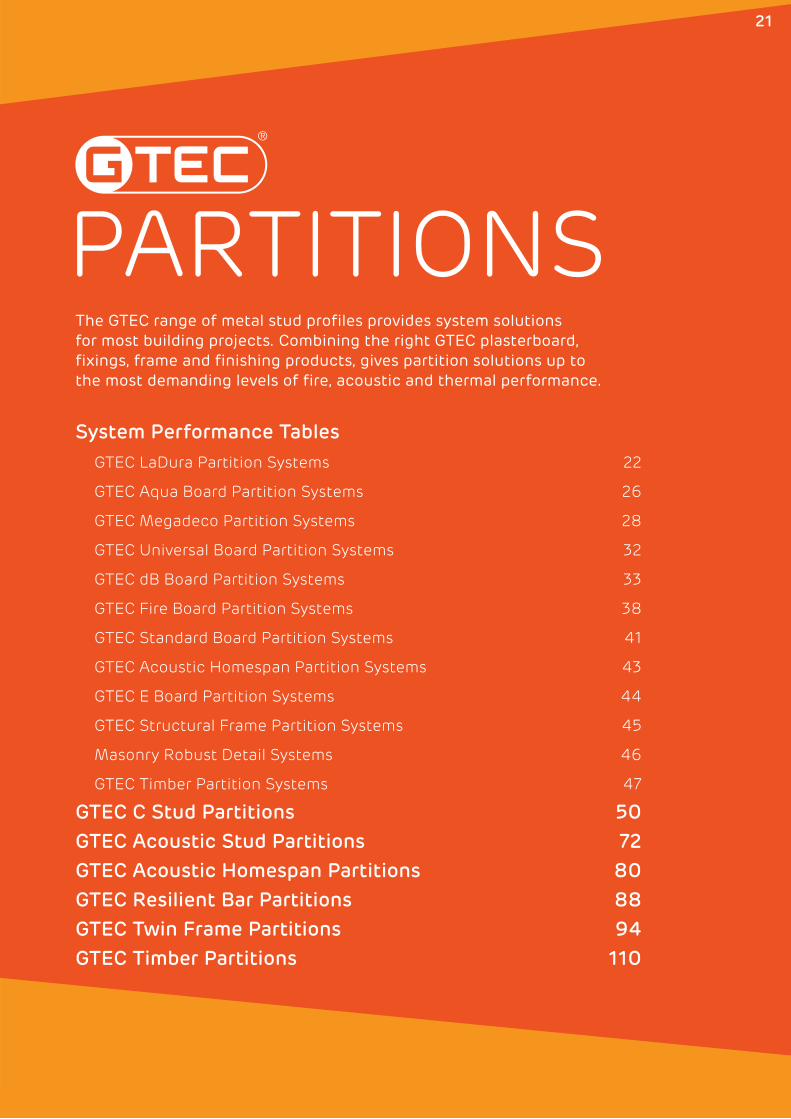
PARTITIONS
System Performance Tables
GTEC LaDura Partition Systems 22
GTEC Aqua Board Partition Systems 26
GTEC Megadeco Partition Systems 28
GTEC Universal Board Partition Systems 32
GTEC dB Board Partition Systems 33
GTEC Fire Board Partition Systems 38
GTEC Standard Board Partition Systems 41
GTEC Acoustic Homespan Partition Systems 43
GTEC E Board Partition Systems 44
GTEC Structural Frame Partition Systems 45
Masonry Robust Detail Systems 46
GTEC Timber Partition Systems 47
GTEC C Stud Partitions 50
GTEC Acoustic Stud Partitions 72
GTEC Acoustic Homespan Partitions 80
GTEC Resilient Bar Partitions 88
GTEC Twin Frame Partitions 94
GTEC Timber Partitions 110
The GTEC range of metal stud profiles provides system solutions for most building projects. Combining the right GTEC plasterboard, fixings, frame and finishing products, gives partition solutions up to the most demanding levels of fire, acoustic and thermal performance.
21
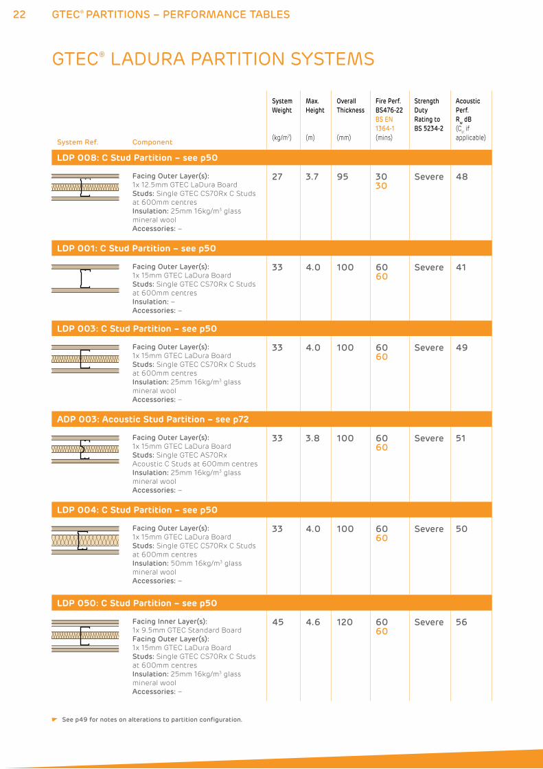
22 GTEC® PARTITIONS – PERFORMANCE TABLES
System Ref. Component
System
Weight
(kg/m2)
Max.
Height
(m)
Overall
Thickness
(mm)
Fire Perf.
BS476-22
BS EN
1364-1
(mins)
Strength
Duty
Rating to
BS 5234-2
Acoustic
Perf.
Rw dB
(Ctr if
applicable)
LDP 008: C Stud Partition – see p50
Facing Outer Layer(s):
1x 12.5mm GTEC LaDura Board
Studs: Single GTEC CS70Rx C Studs
at 600mm centres
Insulation: 25mm 16kg/m3 glass
mineral wool
Accessories: –
27 3.7 95 3030
Severe 48
LDP 001: C Stud Partition – see p50
Facing Outer Layer(s):
1x 15mm GTEC LaDura Board
Studs: Single GTEC CS70Rx C Studs
at 600mm centres
Insulation: –
Accessories: –
33 4.0 100 6060
Severe 41
LDP 003: C Stud Partition – see p50
Facing Outer Layer(s):
1x 15mm GTEC LaDura Board
Studs: Single GTEC CS70Rx C Studs
at 600mm centres
Insulation: 25mm 16kg/m3 glass
mineral wool
Accessories: –
33 4.0 100 6060
Severe 49
ADP 003: Acoustic Stud Partition – see p72
Facing Outer Layer(s):
1x 15mm GTEC LaDura Board
Studs: Single GTEC AS70Rx
Acoustic C Studs at 600mm centres
Insulation: 25mm 16kg/m3 glass
mineral wool
Accessories: –
33 3.8 100 6060
Severe 51
LDP 004: C Stud Partition – see p50
Facing Outer Layer(s):
1x 15mm GTEC LaDura Board
Studs: Single GTEC CS70Rx C Studs
at 600mm centres
Insulation: 50mm 16kg/m3 glass
mineral wool
Accessories: –
33 4.0 100 6060
Severe 50
LDP 050: C Stud Partition – see p50
Facing Inner Layer(s):
1x 9.5mm GTEC Standard Board
Facing Outer Layer(s):
1x 15mm GTEC LaDura Board
Studs: Single GTEC CS70Rx C Studs
at 600mm centres
Insulation: 25mm 16kg/m3 glass
mineral wool
Accessories: –
45 4.6 120 6060
Severe 56
GTEC® LADURA PARTITION SYSTEMS
See p49 for notes on alterations to partition configuration.
23GTEC® PARTITIONS – PERFORMANCE TABLES
ENQUIRYLINE T: 01275 377789 E: [email protected] www.siniat.co.uk
System Ref. Component
System
Weight
(kg/m2)
Max.
Height
(m)
Overall
Thickness
(mm)
Fire Perf.
BS476-22
BS EN
1364-1
(mins)
Strength
Duty
Rating to
BS 5234-2
Acoustic
Perf.
Rw dB
(Ctr if
applicable)
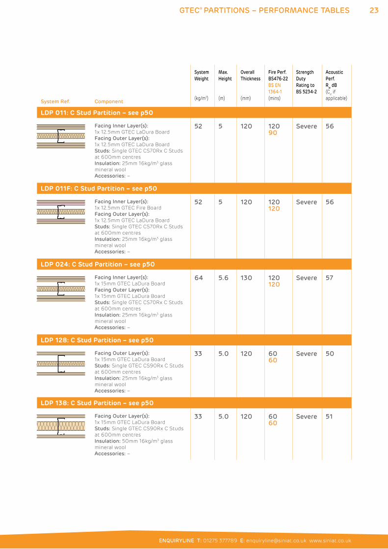
LDP 011: C Stud Partition – see p50
Facing Inner Layer(s):
1x 12.5mm GTEC LaDura Board
Facing Outer Layer(s):
1x 12.5mm GTEC LaDura Board
Studs: Single GTEC CS70Rx C Studs
at 600mm centres
Insulation: 25mm 16kg/m3 glass
mineral wool
Accessories: –
52 5 120 12090
Severe 56
LDP 011F: C Stud Partition – see p50
Facing Inner Layer(s):
1x 12.5mm GTEC Fire Board
Facing Outer Layer(s):
1x 12.5mm GTEC LaDura Board
Studs: Single GTEC CS70Rx C Studs
at 600mm centres
Insulation: 25mm 16kg/m3 glass
mineral wool
Accessories: –
52 5 120 120120
Severe 56
LDP 024: C Stud Partition – see p50
Facing Inner Layer(s):
1x 15mm GTEC LaDura Board
Facing Outer Layer(s):
1x 15mm GTEC LaDura Board
Studs: Single GTEC CS70Rx C Studs
at 600mm centres
Insulation: 25mm 16kg/m3 glass
mineral wool
Accessories: –
64 5.6 130 120120
Severe 57
LDP 128: C Stud Partition – see p50
Facing Outer Layer(s):
1x 15mm GTEC LaDura Board
Studs: Single GTEC CS90Rx C Studs
at 600mm centres
Insulation: 25mm 16kg/m3 glass
mineral wool
Accessories: –
33 5.0 120 6060
Severe 50
LDP 138: C Stud Partition – see p50
Facing Outer Layer(s):
1x 15mm GTEC LaDura Board
Studs: Single GTEC CS90Rx C Studs
at 600mm centres
Insulation: 50mm 16kg/m3 glass
mineral wool
Accessories: –
33 5.0 120 6060
Severe 51
24 GTEC® PARTITIONS – PERFORMANCE TABLES
System Ref. Component
System
Weight
(kg/m2)
Max.
Height
(m)
Overall
Thickness
(mm)
Fire Perf.
BS476-22
BS EN
1364-1
(mins)
Strength
Duty
Rating to
BS 5234-2
Acoustic
Perf.
Rw dB
(Ctr if
applicable)
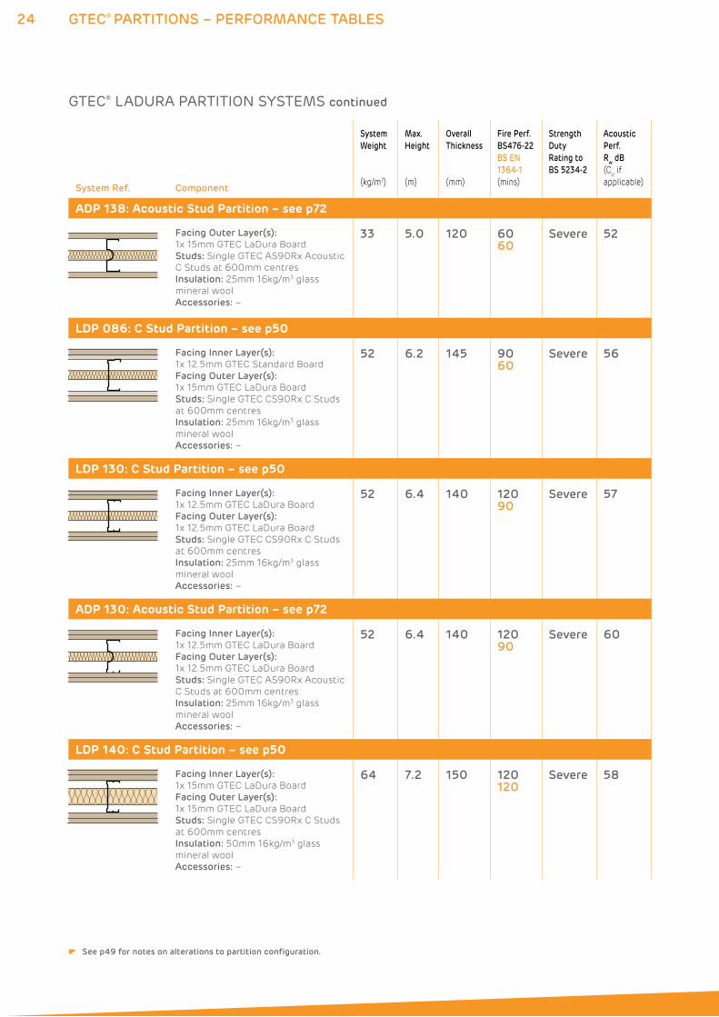
ADP 138: Acoustic Stud Partition – see p72
Facing Outer Layer(s):
1x 15mm GTEC LaDura Board
Studs: Single GTEC AS90Rx Acoustic
C Studs at 600mm centres
Insulation: 25mm 16kg/m3 glass
mineral wool
Accessories: –
33 5.0 120 6060
Severe 52
LDP 086: C Stud Partition – see p50
Facing Inner Layer(s):
1x 12.5mm GTEC Standard Board
Facing Outer Layer(s):
1x 15mm GTEC LaDura Board
Studs: Single GTEC CS90Rx C Studs
at 600mm centres
Insulation: 25mm 16kg/m3 glass
mineral wool
Accessories: –
52 6.2 145 9060
Severe 56
LDP 130: C Stud Partition – see p50
Facing Inner Layer(s):
1x 12.5mm GTEC LaDura Board
Facing Outer Layer(s):
1x 12.5mm GTEC LaDura Board
Studs: Single GTEC CS90Rx C Studs
at 600mm centres
Insulation: 25mm 16kg/m3 glass
mineral wool
Accessories: –
52 6.4 140 12090
Severe 57
ADP 130: Acoustic Stud Partition – see p72
Facing Inner Layer(s):
1x 12.5mm GTEC LaDura Board
Facing Outer Layer(s):
1x 12.5mm GTEC LaDura Board
Studs: Single GTEC AS90Rx Acoustic
C Studs at 600mm centres
Insulation: 25mm 16kg/m3 glass
mineral wool
Accessories: –
52 6.4 140 12090
Severe 60
LDP 140: C Stud Partition – see p50
Facing Inner Layer(s):
1x 15mm GTEC LaDura Board
Facing Outer Layer(s):
1x 15mm GTEC LaDura Board
Studs: Single GTEC CS90Rx C Studs
at 600mm centres
Insulation: 50mm 16kg/m3 glass
mineral wool
Accessories: –
64 7.2 150 120120
Severe 58
GTEC® LADURA PARTITION SYSTEMS continued
See p49 for notes on alterations to partition configuration.
25GTEC® PARTITIONS – PERFORMANCE TABLES
ENQUIRYLINE T: 01275 377789 E: [email protected] www.siniat.co.uk
System Ref. Component
System
Weight
(kg/m2)
Max.
Height
(m)
Overall
Thickness
(mm)
Fire Perf.
BS476-22
BS EN
1364-1
(mins)
Strength
Duty
Rating to
BS 5234-2
Acoustic
Perf.
Rw dB
(Ctr if
applicable)
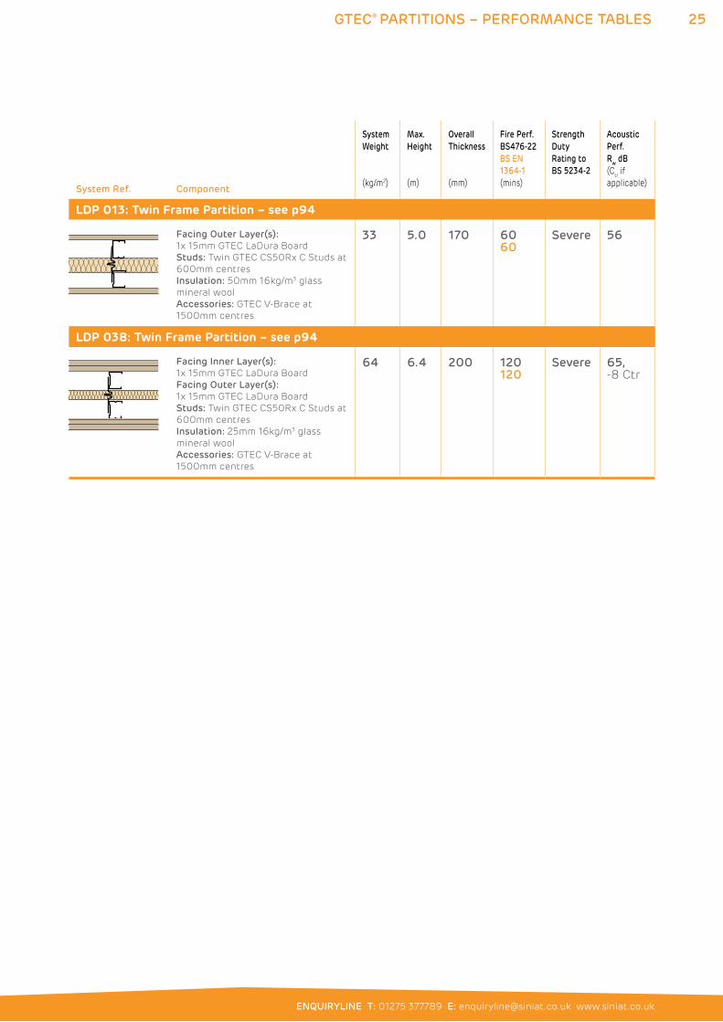
LDP 013: Twin Frame Partition – see p94
Facing Outer Layer(s):
1x 15mm GTEC LaDura Board
Studs: Twin GTEC CS50Rx C Studs at
600mm centres
Insulation: 50mm 16kg/m3 glass
mineral wool
Accessories: GTEC V-Brace at
1500mm centres
33 5.0 170 6060
Severe 56
LDP 038: Twin Frame Partition – see p94
Facing Inner Layer(s):
1x 15mm GTEC LaDura Board
Facing Outer Layer(s):
1x 15mm GTEC LaDura Board
Studs: Twin GTEC CS50Rx C Studs at
600mm centres
Insulation: 25mm 16kg/m3 glass
mineral wool
Accessories: GTEC V-Brace at
1500mm centres
64 6.4 200 120120
Severe 65, -8 Ctr
26 GTEC® PARTITIONS – PERFORMANCE TABLES
System Ref. Component
System
Weight
(kg/m2)
Max.
Height
(m)
Overall
Thickness
(mm)
Fire Perf.
BS476-22
BS EN
1364-1
(mins)
Strength
Duty
Rating to
BS 5234-2
Acoustic
Perf.
Rw dB
(Ctr if
applicable)
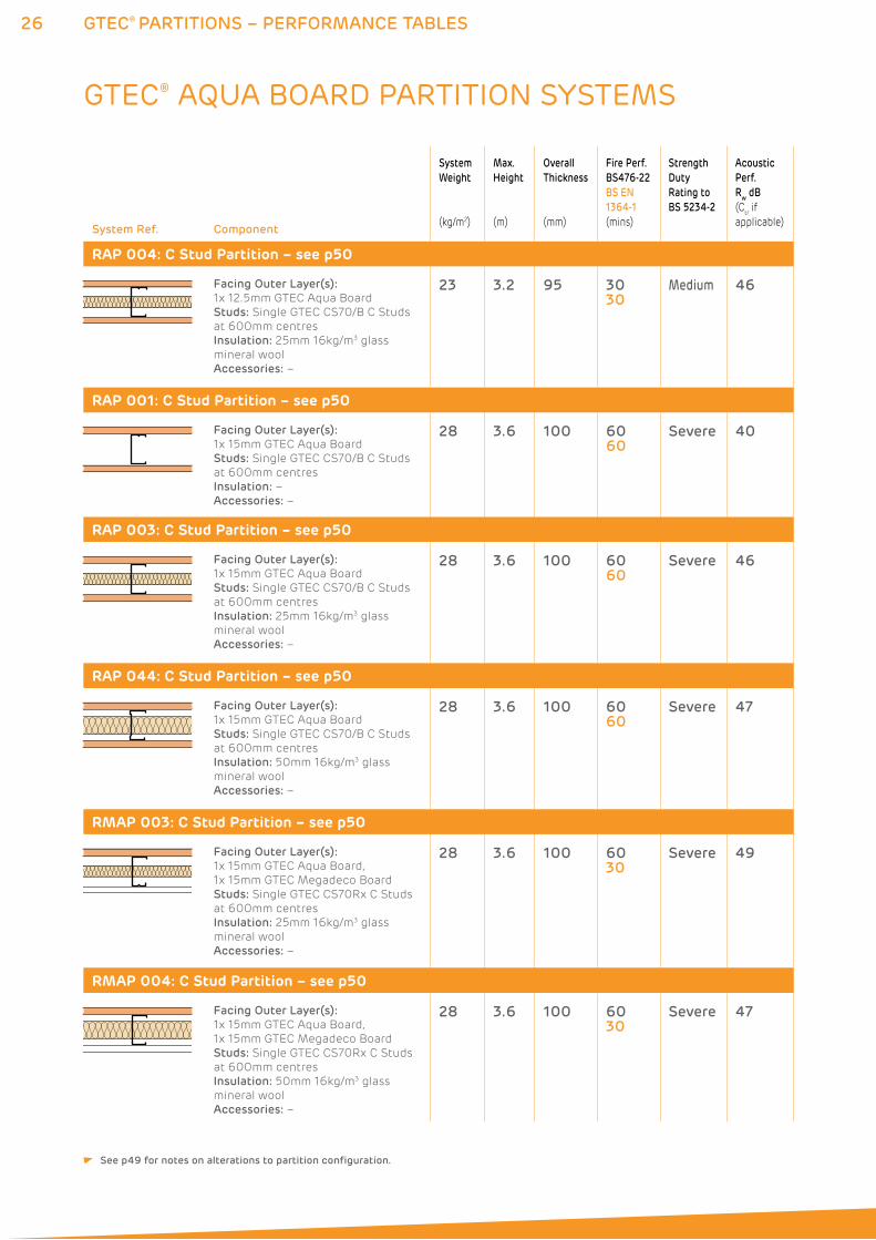
RAP 004: C Stud Partition – see p50
Facing Outer Layer(s):
1x 12.5mm GTEC Aqua Board
Studs: Single GTEC CS70/B C Studs
at 600mm centres
Insulation: 25mm 16kg/m3 glass
mineral wool
Accessories: –
23 3.2 95 3030
Medium 46
RAP 001: C Stud Partition – see p50
Facing Outer Layer(s):
1x 15mm GTEC Aqua Board
Studs: Single GTEC CS70/B C Studs
at 600mm centres
Insulation: –
Accessories: –
28 3.6 100 6060
Severe 40
RAP 003: C Stud Partition – see p50
Facing Outer Layer(s):
1x 15mm GTEC Aqua Board
Studs: Single GTEC CS70/B C Studs
at 600mm centres
Insulation: 25mm 16kg/m3 glass
mineral wool
Accessories: –
28 3.6 100 6060
Severe 46
RAP 044: C Stud Partition – see p50
Facing Outer Layer(s):
1x 15mm GTEC Aqua Board
Studs: Single GTEC CS70/B C Studs
at 600mm centres
Insulation: 50mm 16kg/m3 glass
mineral wool
Accessories: –
28 3.6 100 6060
Severe 47
RMAP 003: C Stud Partition – see p50
Facing Outer Layer(s):
1x 15mm GTEC Aqua Board,
1x 15mm GTEC Megadeco Board
Studs: Single GTEC CS70Rx C Studs
at 600mm centres
Insulation: 25mm 16kg/m3 glass
mineral wool
Accessories: –
28 3.6 100 6030
Severe 49
RMAP 004: C Stud Partition – see p50
Facing Outer Layer(s):
1x 15mm GTEC Aqua Board,
1x 15mm GTEC Megadeco Board
Studs: Single GTEC CS70Rx C Studs
at 600mm centres
Insulation: 50mm 16kg/m3 glass
mineral wool
Accessories: –
28 3.6 100 6030
Severe 47
GTEC® AQUA BOARD PARTITION SYSTEMS
See p49 for notes on alterations to partition configuration.
27GTEC® PARTITIONS – PERFORMANCE TABLES
ENQUIRYLINE T: 01275 377789 E: [email protected] www.siniat.co.uk
System Ref. Component
System
Weight
(kg/m2)
Max.
Height
(m)
Overall
Thickness
(mm)
Fire Perf.
BS476-22
BS EN
1364-1
(mins)
Strength
Duty
Rating to
BS 5234-2
Acoustic
Perf.
Rw dB
(Ctr if
applicable)
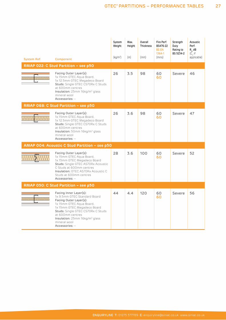
RMAP 022: C Stud Partition – see p50
Facing Outer Layer(s):
1x 15mm GTEC Aqua Board,
1x 12.5mm GTEC Megadeco Board
Studs: Single GTEC CS70Rx C Studs
at 600mm centres
Insulation: 25mm 16kg/m3 glass
mineral wool
Accessories: –
26 3.5 98 6060
Severe 46
RMAP 068: C Stud Partition – see p50
Facing Outer Layer(s):
1x 15mm GTEC Aqua Board,
1x 12.5mm GTEC Megadeco Board
Studs: Single GTEC CS70Rx C Studs
at 600mm centres
Insulation: 50mm 16kg/m3 glass
mineral wool
Accessories: –
26 3.6 98 6060
Severe 47
AMAP 004: Acoustic C Stud Partition – see p50
Facing Outer Layer(s):
1x 15mm GTEC Aqua Board,
1x 15mm GTEC Megadeco Board
Studs: Single GTEC AS70Rx Acoustic
C Studs at 600mm centres
Insulation: GTEC AS70Rx Acoustic C
Studs at 600mm centres
Accessories: –
28 3.6 100 6060
Severe 52
RMAP 050: C Stud Partition – see p50
Facing Inner Layer(s):
1x 9.5mm GTEC Standard Board
Facing Outer Layer(s):
1x 15mm GTEC Aqua Board,
1x 15mm GTEC Megadeco Board
Studs: Single GTEC CS70Rx C Studs
at 600mm centres
Insulation: 25mm 16kg/m3 glass
mineral wool
Accessories: –
44 4.4 120 6060
Severe 56
28 GTEC® PARTITIONS – PERFORMANCE TABLES
System Ref. Component
System
Weight
(kg/m2)
Max.
Height
(m)
Overall
Thickness
(mm)
Fire Perf.
BS476-22
BS EN
1364-1
(mins)
Strength
Duty
Rating to
BS 5234-2
Acoustic
Perf.
Rw dB
(Ctr if
applicable)
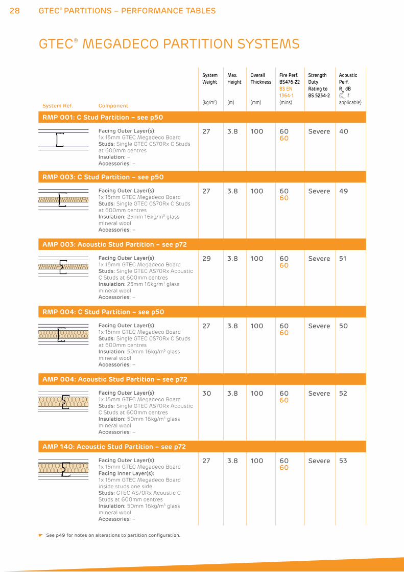
RMP 001: C Stud Partition – see p50
Facing Outer Layer(s):
1x 15mm GTEC Megadeco Board
Studs: Single GTEC CS70Rx C Studs
at 600mm centres
Insulation: –
Accessories: –
27 3.8 100 6060
Severe 40
RMP 003: C Stud Partition – see p50
Facing Outer Layer(s):
1x 15mm GTEC Megadeco Board
Studs: Single GTEC CS70Rx C Studs
at 600mm centres
Insulation: 25mm 16kg/m3 glass
mineral wool
Accessories: –
27 3.8 100 6060
Severe 49
AMP 003: Acoustic Stud Partition – see p72
Facing Outer Layer(s):
1x 15mm GTEC Megadeco Board
Studs: Single GTEC AS70Rx Acoustic
C Studs at 600mm centres
Insulation: 25mm 16kg/m3 glass
mineral wool
Accessories: –
29 3.8 100 6060
Severe 51
RMP 004: C Stud Partition – see p50
Facing Outer Layer(s):
1x 15mm GTEC Megadeco Board
Studs: Single GTEC CS70Rx C Studs
at 600mm centres
Insulation: 50mm 16kg/m3 glass
mineral wool
Accessories: –
27 3.8 100 6060
Severe 50
AMP 004: Acoustic Stud Partition – see p72
Facing Outer Layer(s):
1x 15mm GTEC Megadeco Board
Studs: Single GTEC AS70Rx Acoustic
C Studs at 600mm centres
Insulation: 50mm 16kg/m3 glass
mineral wool
Accessories: –
30 3.8 100 6060
Severe 52
AMP 140: Acoustic Stud Partition – see p72
Facing Outer Layer(s):
1x 15mm GTEC Megadeco Board
Facing Inner Layer(s):
1x 15mm GTEC Megadeco Board
inside studs one side
Studs: GTEC AS70Rx Acoustic C
Studs at 600mm centres
Insulation: 50mm 16kg/m3 glass
mineral wool
Accessories: –
27 3.8 100 6060
Severe 53
GTEC® MEGADECO PARTITION SYSTEMS
See p49 for notes on alterations to partition configuration.
29GTEC® PARTITIONS – PERFORMANCE TABLES
ENQUIRYLINE T: 01275 377789 E: [email protected] www.siniat.co.uk
System Ref. Component
System
Weight
(kg/m2)
Max.
Height
(m)
Overall
Thickness
(mm)
Fire Perf.
BS476-22
BS EN
1364-1
(mins)
Strength
Duty
Rating to
BS 5234-2
Acoustic
Perf.
Rw dB
(Ctr if
applicable)
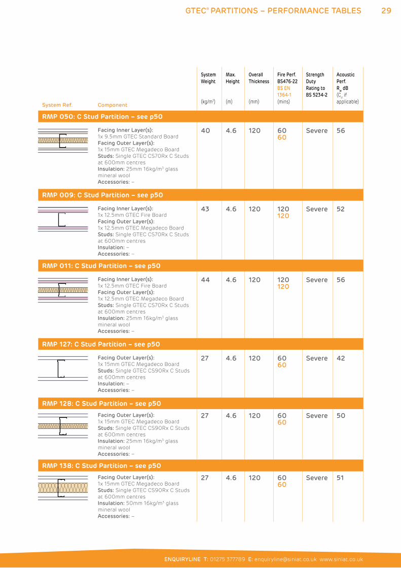
RMP 050: C Stud Partition – see p50
Facing Inner Layer(s):
1x 9.5mm GTEC Standard Board
Facing Outer Layer(s):
1x 15mm GTEC Megadeco Board
Studs: Single GTEC CS70Rx C Studs
at 600mm centres
Insulation: 25mm 16kg/m3 glass
mineral wool
Accessories: –
40 4.6 120 6060
Severe 56
RMP 009: C Stud Partition – see p50
Facing Inner Layer(s):
1x 12.5mm GTEC Fire Board
Facing Outer Layer(s):
1x 12.5mm GTEC Megadeco Board
Studs: Single GTEC CS70Rx C Studs
at 600mm centres
Insulation: –
Accessories: –
43 4.6 120 120120
Severe 52
RMP 011: C Stud Partition – see p50
Facing Inner Layer(s):
1x 12.5mm GTEC Fire Board
Facing Outer Layer(s):
1x 12.5mm GTEC Megadeco Board
Studs: Single GTEC CS70Rx C Studs
at 600mm centres
Insulation: 25mm 16kg/m3 glass
mineral wool
Accessories: –
44 4.6 120 120120
Severe 56
RMP 127: C Stud Partition – see p50
Facing Outer Layer(s):
1x 15mm GTEC Megadeco Board
Studs: Single GTEC CS90Rx C Studs
at 600mm centres
Insulation: –
Accessories: –
27 4.6 120 6060
Severe 42
RMP 128: C Stud Partition – see p50
Facing Outer Layer(s):
1x 15mm GTEC Megadeco Board
Studs: Single GTEC CS90Rx C Studs
at 600mm centres
Insulation: 25mm 16kg/m3 glass
mineral wool
Accessories: –
27 4.6 120 6060
Severe 50
RMP 138: C Stud Partition – see p50
Facing Outer Layer(s):
1x 15mm GTEC Megadeco Board
Studs: Single GTEC CS90Rx C Studs
at 600mm centres
Insulation: 50mm 16kg/m3 glass
mineral wool
Accessories: –
27 4.6 120 6060
Severe 51
30 GTEC® PARTITIONS – PERFORMANCE TABLES
System Ref. Component
System
Weight
(kg/m2)
Max.
Height
(m)
Overall
Thickness
(mm)
Fire Perf.
BS476-22
BS EN
1364-1
(mins)
Strength
Duty
Rating to
BS 5234-2
Acoustic
Perf.
Rw dB
(Ctr if
applicable)
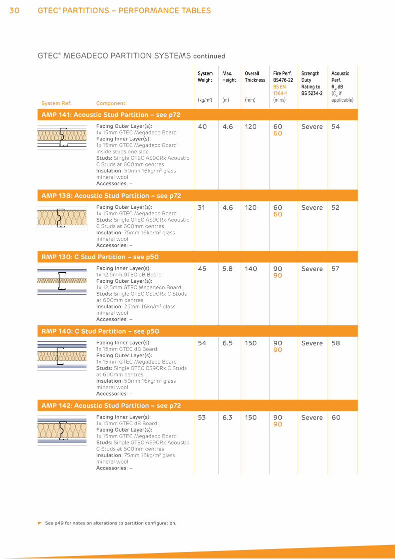
AMP 141: Acoustic Stud Partition – see p72
Facing Outer Layer(s):
1x 15mm GTEC Megadeco Board
Facing Inner Layer(s):
1x 15mm GTEC Megadeco Board
inside studs one side
Studs: Single GTEC AS90Rx Acoustic
C Studs at 600mm centres
Insulation: 50mm 16kg/m3 glass
mineral wool
Accessories: –
40 4.6 120 6060
Severe 54
AMP 138: Acoustic Stud Partition – see p72
Facing Outer Layer(s):
1x 15mm GTEC Megadeco Board
Studs: Single GTEC AS90Rx Acoustic
C Studs at 600mm centres
Insulation: 75mm 16kg/m3 glass
mineral wool
Accessories: –
31 4.6 120 6060
Severe 52
RMP 130: C Stud Partition – see p50
Facing Inner Layer(s):
1x 12.5mm GTEC dB Board
Facing Outer Layer(s):
1x 12.5mm GTEC Megadeco Board
Studs: Single GTEC CS90Rx C Studs
at 600mm centres
Insulation: 25mm 16kg/m3 glass
mineral wool
Accessories: –
45 5.8 140 9090
Severe 57
RMP 140: C Stud Partition – see p50
Facing Inner Layer(s):
1x 15mm GTEC dB Board
Facing Outer Layer(s):
1x 15mm GTEC Megadeco Board
Studs: Single GTEC CS90Rx C Studs
at 600mm centres
Insulation: 50mm 16kg/m3 glass
mineral wool
Accessories: –
54 6.5 150 9090
Severe 58
AMP 142: Acoustic Stud Partition – see p72
Facing Inner Layer(s):
1x 15mm GTEC dB Board
Facing Outer Layer(s):
1x 15mm GTEC Megadeco Board
Studs: Single GTEC AS90Rx Acoustic
C Studs at 600mm centres
Insulation: 75mm 16kg/m3 glass
mineral wool
Accessories: –
53 6.3 150 9090
Severe 60
GTEC® MEGADECO PARTITION SYSTEMS continued
See p49 for notes on alterations to partition configuration.
31GTEC® PARTITIONS – PERFORMANCE TABLES
ENQUIRYLINE T: 01275 377789 E: [email protected] www.siniat.co.uk
System Ref. Component
System
Weight
(kg/m2)
Max.
Height
(m)
Overall
Thickness
(mm)
Fire Perf.
BS476-22
BS EN
1364-1
(mins)
Strength
Duty
Rating to
BS 5234-2
Acoustic
Perf.
Rw dB
(Ctr if
applicable)
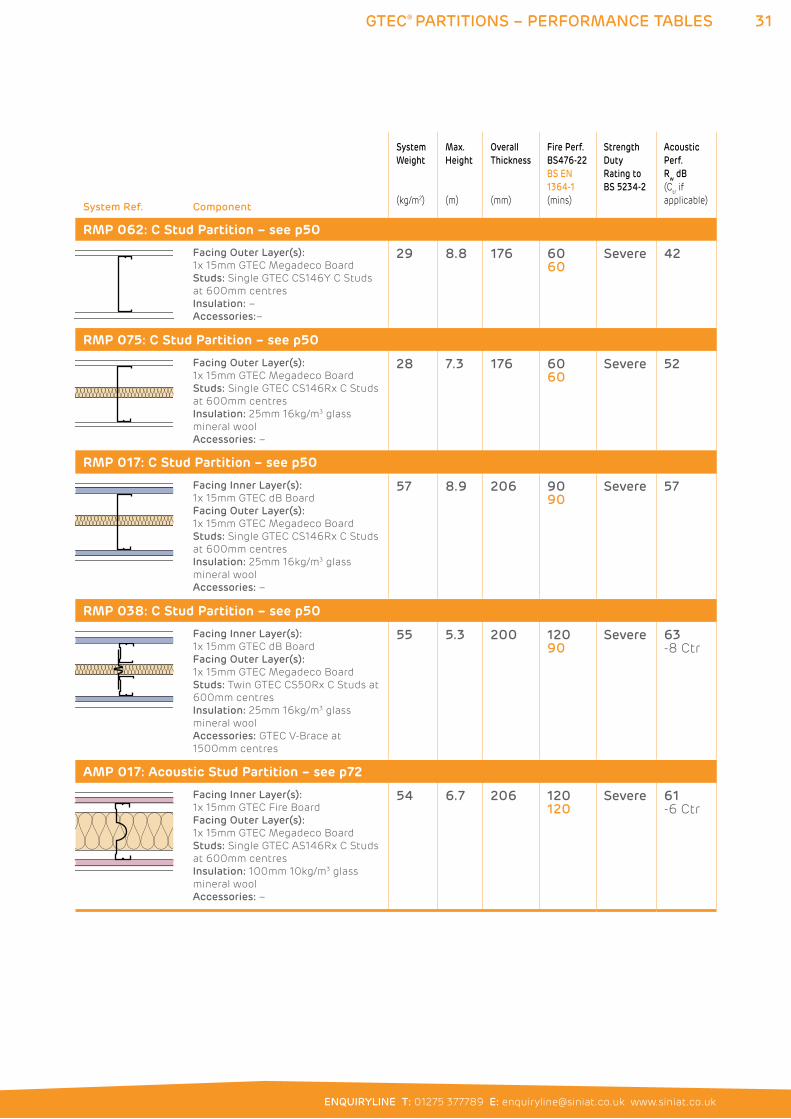
RMP 062: C Stud Partition – see p50
Facing Outer Layer(s):
1x 15mm GTEC Megadeco Board
Studs: Single GTEC CS146Y C Studs
at 600mm centres
Insulation: –
Accessories:–
29 8.8 176 6060
Severe 42
RMP 075: C Stud Partition – see p50
Facing Outer Layer(s):
1x 15mm GTEC Megadeco Board
Studs: Single GTEC CS146Rx C Studs
at 600mm centres
Insulation: 25mm 16kg/m3 glass
mineral wool
Accessories: –
28 7.3 176 6060
Severe 52
RMP 017: C Stud Partition – see p50
Facing Inner Layer(s):
1x 15mm GTEC dB Board
Facing Outer Layer(s):
1x 15mm GTEC Megadeco Board
Studs: Single GTEC CS146Rx C Studs
at 600mm centres
Insulation: 25mm 16kg/m3 glass
mineral wool
Accessories: –
57 8.9 206 9090
Severe 57
RMP 038: C Stud Partition – see p50
Facing Inner Layer(s):
1x 15mm GTEC dB Board
Facing Outer Layer(s):
1x 15mm GTEC Megadeco Board
Studs: Twin GTEC CS50Rx C Studs at
600mm centres
Insulation: 25mm 16kg/m3 glass
mineral wool
Accessories: GTEC V-Brace at
1500mm centres
55 5.3 200 12090
Severe 63 -8 Ctr
AMP 017: Acoustic Stud Partition – see p72
Facing Inner Layer(s):
1x 15mm GTEC Fire Board
Facing Outer Layer(s):
1x 15mm GTEC Megadeco Board
Studs: Single GTEC AS146Rx C Studs
at 600mm centres
Insulation: 100mm 10kg/m3 glass
mineral wool
Accessories: –
54 6.7 206 120120
Severe 61 -6 Ctr
32 GTEC® PARTITIONS – PERFORMANCE TABLES
System Ref. Component
System
Weight
(kg/m2)
Max.
Height
(m)
Overall
Thickness
(mm)
Fire Perf.
BS476-22
BS EN
1364-1
(mins)
Strength
Duty
Rating to
BS 5234-2
Acoustic
Perf.
Rw dB
(Ctr if
applicable)
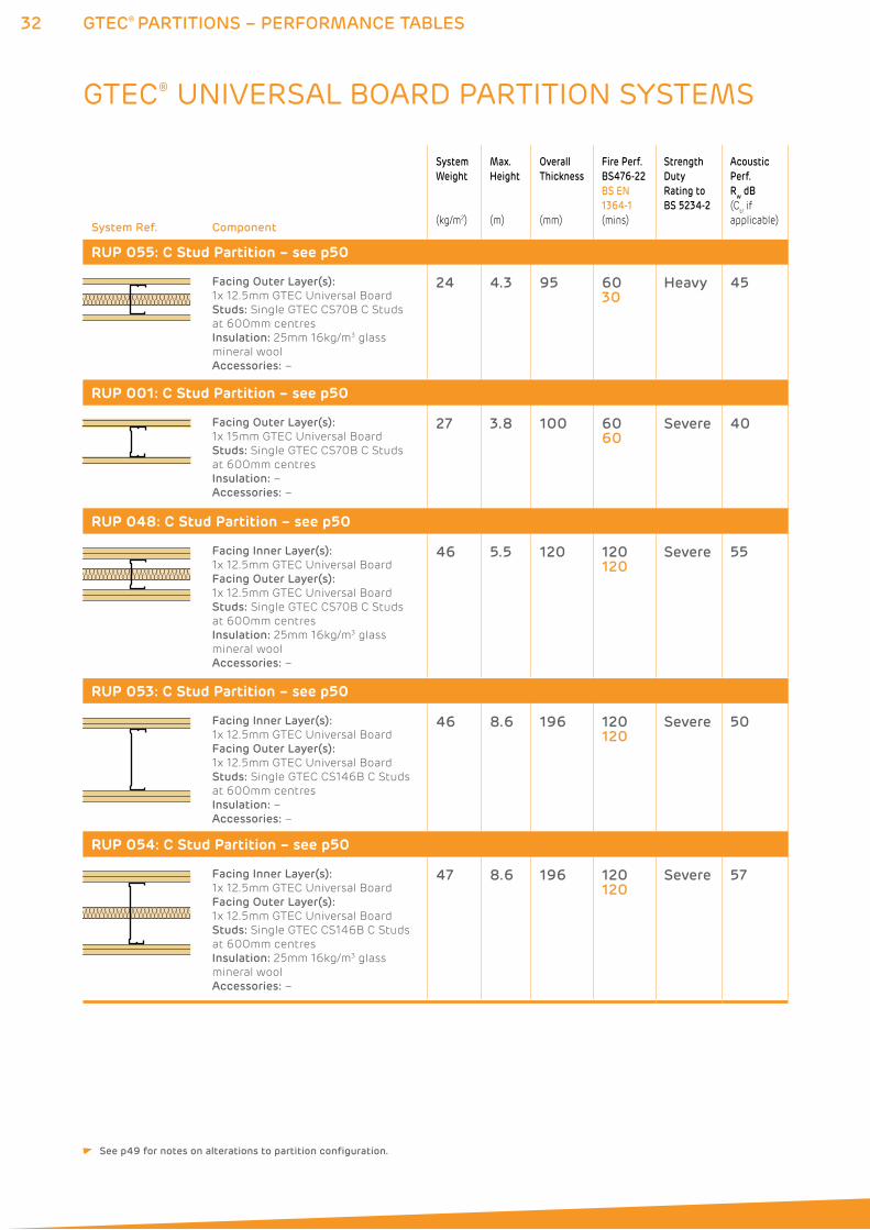
RUP 055: C Stud Partition – see p50
Facing Outer Layer(s):
1x 12.5mm GTEC Universal Board
Studs: Single GTEC CS70B C Studs
at 600mm centres
Insulation: 25mm 16kg/m3 glass
mineral wool
Accessories: –
24 4.3 95 6030
Heavy 45
RUP 001: C Stud Partition – see p50
Facing Outer Layer(s):
1x 15mm GTEC Universal Board
Studs: Single GTEC CS70B C Studs
at 600mm centres
Insulation: –
Accessories: –
27 3.8 100 6060
Severe 40
RUP 048: C Stud Partition – see p50
Facing Inner Layer(s):
1x 12.5mm GTEC Universal Board
Facing Outer Layer(s):
1x 12.5mm GTEC Universal Board
Studs: Single GTEC CS70B C Studs
at 600mm centres
Insulation: 25mm 16kg/m3 glass
mineral wool
Accessories: –
46 5.5 120 120120
Severe 55
RUP 053: C Stud Partition – see p50
Facing Inner Layer(s):
1x 12.5mm GTEC Universal Board
Facing Outer Layer(s):
1x 12.5mm GTEC Universal Board
Studs: Single GTEC CS146B C Studs
at 600mm centres
Insulation: –
Accessories: –
46 8.6 196 120120
Severe 50
RUP 054: C Stud Partition – see p50
Facing Inner Layer(s):
1x 12.5mm GTEC Universal Board
Facing Outer Layer(s):
1x 12.5mm GTEC Universal Board
Studs: Single GTEC CS146B C Studs
at 600mm centres
Insulation: 25mm 16kg/m3 glass
mineral wool
Accessories: –
47 8.6 196 120120
Severe 57
GTEC® UNIVERSAL BOARD PARTITION SYSTEMS
See p49 for notes on alterations to partition configuration.
33GTEC® PARTITIONS – PERFORMANCE TABLES
ENQUIRYLINE T: 01275 377789 E: [email protected] www.siniat.co.uk
System Ref. Component
System
Weight
(kg/m2)
Max.
Height
(m)
Overall
Thickness
(mm)
Fire Perf.
BS476-22
BS EN
1364-1
(mins)
Strength
Duty
Rating to
BS 5234-2
Acoustic
Perf.
Rw dB
(Ctr if
applicable)
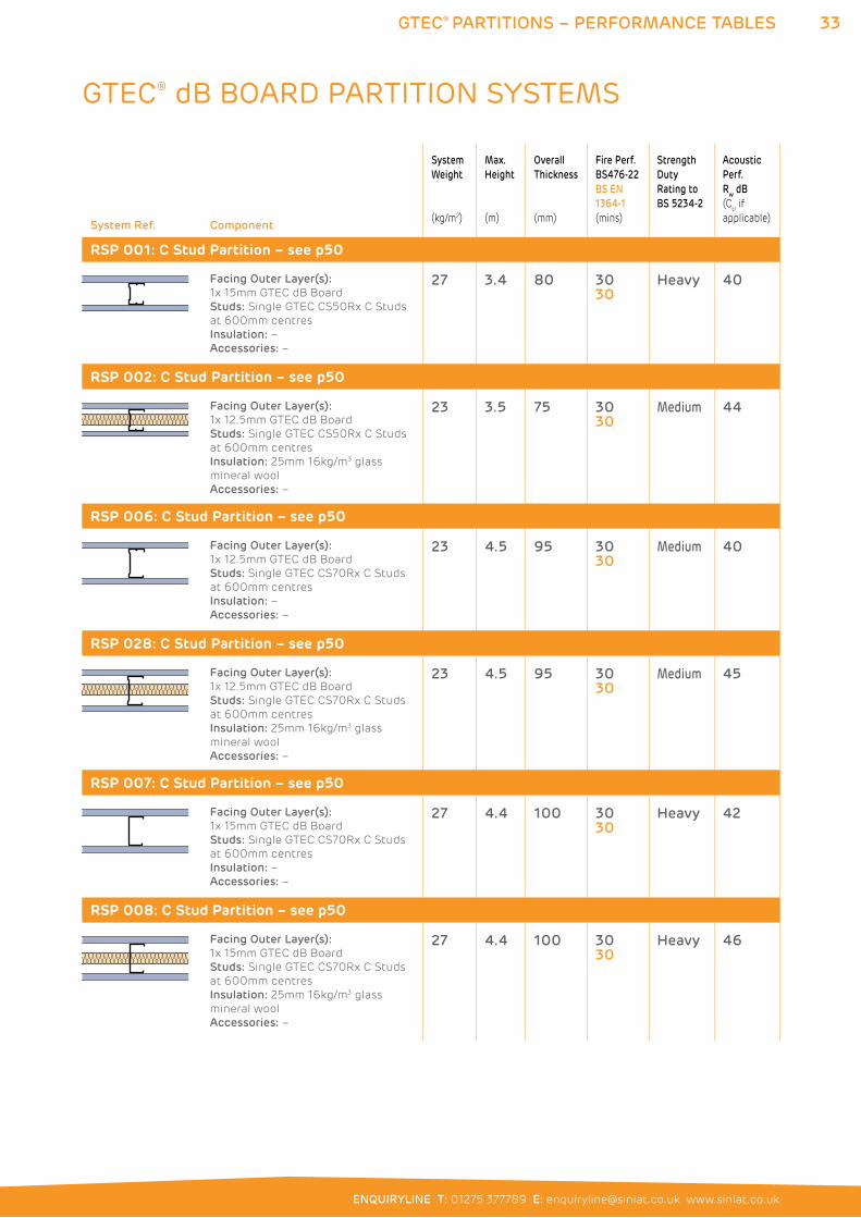
RSP 001: C Stud Partition – see p50
Facing Outer Layer(s):
1x 15mm GTEC dB Board
Studs: Single GTEC CS50Rx C Studs
at 600mm centres
Insulation: –
Accessories: –
27 3.4 80 3030
Heavy 40
RSP 002: C Stud Partition – see p50
Facing Outer Layer(s):
1x 12.5mm GTEC dB Board
Studs: Single GTEC CS50Rx C Studs
at 600mm centres
Insulation: 25mm 16kg/m3 glass
mineral wool
Accessories: –
23 3.5 75 3030
Medium 44
RSP 006: C Stud Partition – see p50
Facing Outer Layer(s):
1x 12.5mm GTEC dB Board
Studs: Single GTEC CS70Rx C Studs
at 600mm centres
Insulation: –
Accessories: –
23 4.5 95 3030
Medium 40
RSP 028: C Stud Partition – see p50
Facing Outer Layer(s):
1x 12.5mm GTEC dB Board
Studs: Single GTEC CS70Rx C Studs
at 600mm centres
Insulation: 25mm 16kg/m3 glass
mineral wool
Accessories: –
23 4.5 95 3030
Medium 45
RSP 007: C Stud Partition – see p50
Facing Outer Layer(s):
1x 15mm GTEC dB Board
Studs: Single GTEC CS70Rx C Studs
at 600mm centres
Insulation: –
Accessories: –
27 4.4 100 3030
Heavy 42
RSP 008: C Stud Partition – see p50
Facing Outer Layer(s):
1x 15mm GTEC dB Board
Studs: Single GTEC CS70Rx C Studs
at 600mm centres
Insulation: 25mm 16kg/m3 glass
mineral wool
Accessories: –
27 4.4 100 3030
Heavy 46
GTEC® dB BOARD PARTITION SYSTEMS
34 GTEC® PARTITIONS – PERFORMANCE TABLES
System Ref. Component
System
Weight
(kg/m2)
Max.
Height
(m)
Overall
Thickness
(mm)
Fire Perf.
BS476-22
BS EN
1364-1
(mins)
Strength
Duty
Rating to
BS 5234-2
Acoustic
Perf.
Rw dB
(Ctr if
applicable)
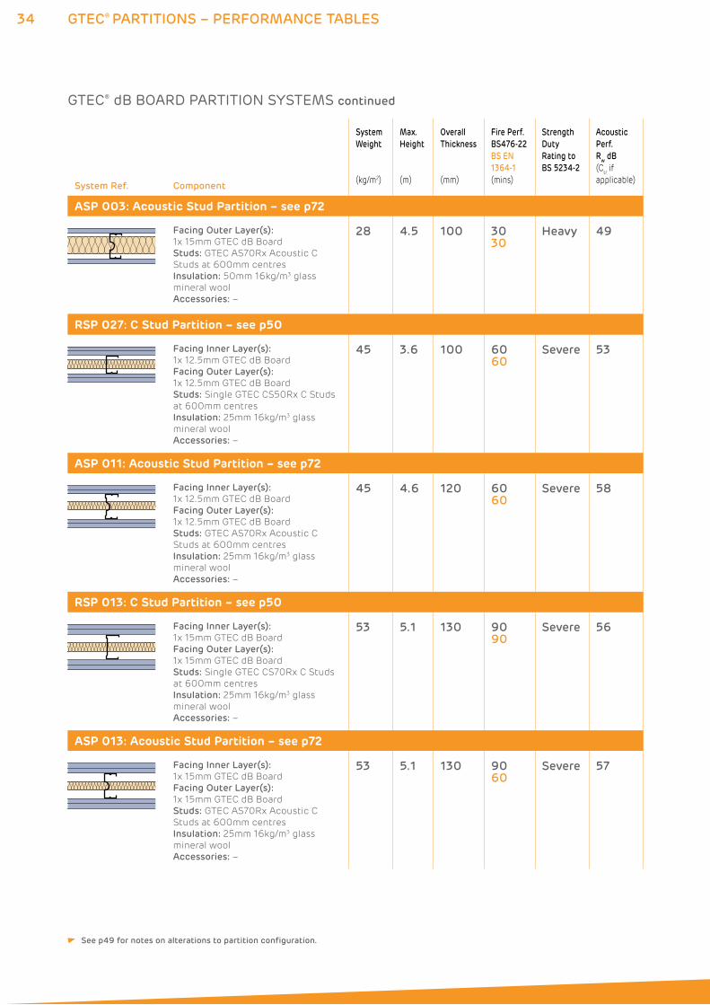
ASP 003: Acoustic Stud Partition – see p72
Facing Outer Layer(s):
1x 15mm GTEC dB Board
Studs: GTEC AS70Rx Acoustic C
Studs at 600mm centres
Insulation: 50mm 16kg/m3 glass
mineral wool
Accessories: –
28 4.5 100 3030
Heavy 49
RSP 027: C Stud Partition – see p50
Facing Inner Layer(s):
1x 12.5mm GTEC dB Board
Facing Outer Layer(s):
1x 12.5mm GTEC dB Board
Studs: Single GTEC CS50Rx C Studs
at 600mm centres
Insulation: 25mm 16kg/m3 glass
mineral wool
Accessories: –
45 3.6 100 6060
Severe 53
ASP 011: Acoustic Stud Partition – see p72
Facing Inner Layer(s):
1x 12.5mm GTEC dB Board
Facing Outer Layer(s):
1x 12.5mm GTEC dB Board
Studs: GTEC AS70Rx Acoustic C
Studs at 600mm centres
Insulation: 25mm 16kg/m3 glass
mineral wool
Accessories: –
45 4.6 120 6060
Severe 58
RSP 013: C Stud Partition – see p50
Facing Inner Layer(s):
1x 15mm GTEC dB Board
Facing Outer Layer(s):
1x 15mm GTEC dB Board
Studs: Single GTEC CS70Rx C Studs
at 600mm centres
Insulation: 25mm 16kg/m3 glass
mineral wool
Accessories: –
53 5.1 130 9090
Severe 56
ASP 013: Acoustic Stud Partition – see p72
Facing Inner Layer(s):
1x 15mm GTEC dB Board
Facing Outer Layer(s):
1x 15mm GTEC dB Board
Studs: GTEC AS70Rx Acoustic C
Studs at 600mm centres
Insulation: 25mm 16kg/m3 glass
mineral wool
Accessories: –
53 5.1 130 9060
Severe 57
GTEC® dB BOARD PARTITION SYSTEMS continued
See p49 for notes on alterations to partition configuration.
35GTEC® PARTITIONS – PERFORMANCE TABLES
ENQUIRYLINE T: 01275 377789 E: [email protected] www.siniat.co.uk
System Ref. Component
System
Weight
(kg/m2)
Max.
Height
(m)
Overall
Thickness
(mm)
Fire Perf.
BS476-22
BS EN
1364-1
(mins)
Strength
Duty
Rating to
BS 5234-2
Acoustic
Perf.
Rw dB
(Ctr if
applicable)
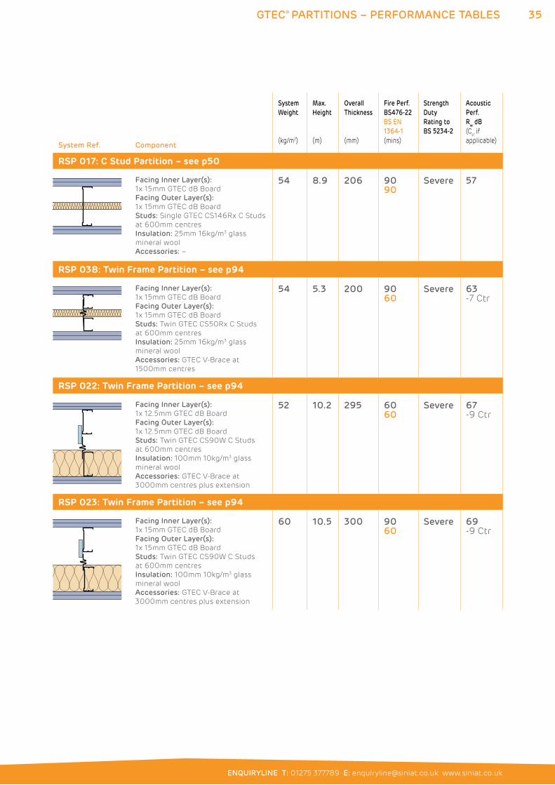
RSP 017: C Stud Partition – see p50
Facing Inner Layer(s):
1x 15mm GTEC dB Board
Facing Outer Layer(s):
1x 15mm GTEC dB Board
Studs: Single GTEC CS146Rx C Studs
at 600mm centres
Insulation: 25mm 16kg/m3 glass
mineral wool
Accessories: –
54 8.9 206 9090
Severe 57
RSP 038: Twin Frame Partition – see p94
Facing Inner Layer(s):
1x 15mm GTEC dB Board
Facing Outer Layer(s):
1x 15mm GTEC dB Board
Studs: Twin GTEC CS50Rx C Studs
at 600mm centres
Insulation: 25mm 16kg/m3 glass
mineral wool
Accessories: GTEC V-Brace at
1500mm centres
54 5.3 200 9060
Severe 63 -7 Ctr
RSP 022: Twin Frame Partition – see p94
Facing Inner Layer(s):
1x 12.5mm GTEC dB Board
Facing Outer Layer(s):
1x 12.5mm GTEC dB Board
Studs: Twin GTEC CS90W C Studs
at 600mm centres
Insulation: 100mm 10kg/m3 glass
mineral wool
Accessories: GTEC V-Brace at
3000mm centres plus extension
52 10.2 295 6060
Severe 67 -9 Ctr
RSP 023: Twin Frame Partition – see p94
Facing Inner Layer(s):
1x 15mm GTEC dB Board
Facing Outer Layer(s):
1x 15mm GTEC dB Board
Studs: Twin GTEC CS90W C Studs
at 600mm centres
Insulation: 100mm 10kg/m3 glass
mineral wool
Accessories: GTEC V-Brace at
3000mm centres plus extension
60 10.5 300 9060
Severe 69 -9 Ctr
36 GTEC® PARTITIONS – PERFORMANCE TABLES
System Ref. Component
System
Weight
(kg/m2)
Max.
Height
(m)
Overall
Thickness
(mm)
Fire Perf.
BS476-22
BS EN
1364-1
(mins)
Strength
Duty
Rating to
BS 5234-2
Acoustic
Perf.
Rw dB
(Ctr if
applicable)
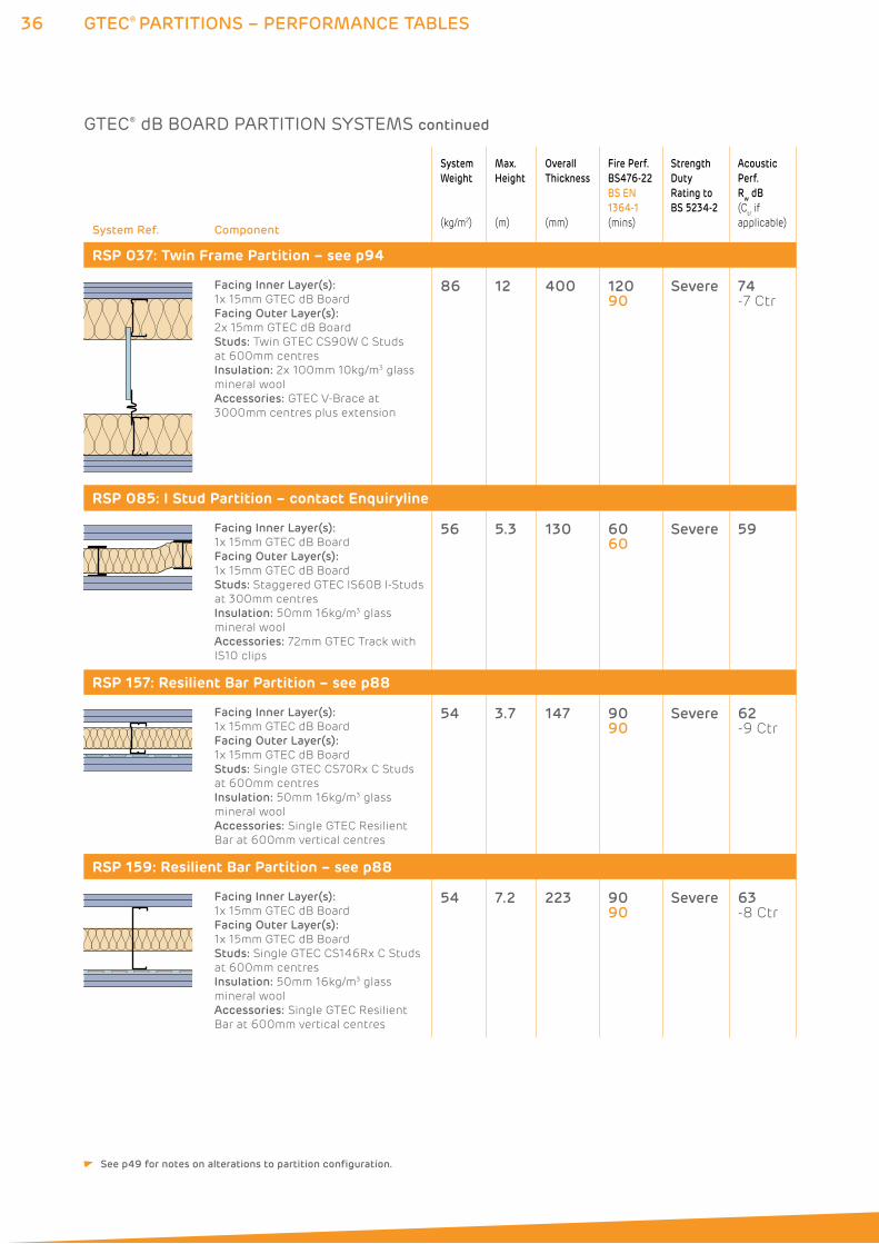
RSP 037: Twin Frame Partition – see p94
Facing Inner Layer(s):
1x 15mm GTEC dB Board
Facing Outer Layer(s):
2x 15mm GTEC dB Board
Studs: Twin GTEC CS90W C Studs
at 600mm centres
Insulation: 2x 100mm 10kg/m3 glass
mineral wool
Accessories: GTEC V-Brace at
3000mm centres plus extension
86 12 400 12090
Severe 74 -7 Ctr
RSP 085: I Stud Partition – contact Enquiryline
Facing Inner Layer(s):
1x 15mm GTEC dB Board
Facing Outer Layer(s):
1x 15mm GTEC dB Board
Studs: Staggered GTEC IS60B I-Studs
at 300mm centres
Insulation: 50mm 16kg/m3 glass
mineral wool
Accessories: 72mm GTEC Track with
IS10 clips
56 5.3 130 6060
Severe 59
RSP 157: Resilient Bar Partition – see p88
Facing Inner Layer(s):
1x 15mm GTEC dB Board
Facing Outer Layer(s):
1x 15mm GTEC dB Board
Studs: Single GTEC CS70Rx C Studs
at 600mm centres
Insulation: 50mm 16kg/m3 glass
mineral wool
Accessories: Single GTEC Resilient
Bar at 600mm vertical centres
54 3.7 147 9090
Severe 62 -9 Ctr
RSP 159: Resilient Bar Partition – see p88
Facing Inner Layer(s):
1x 15mm GTEC dB Board
Facing Outer Layer(s):
1x 15mm GTEC dB Board
Studs: Single GTEC CS146Rx C Studs
at 600mm centres
Insulation: 50mm 16kg/m3 glass
mineral wool
Accessories: Single GTEC Resilient
Bar at 600mm vertical centres
54 7.2 223 9090
Severe 63 -8 Ctr
GTEC® dB BOARD PARTITION SYSTEMS continued
See p49 for notes on alterations to partition configuration.
37GTEC® PARTITIONS – PERFORMANCE TABLES
ENQUIRYLINE T: 01275 377789 E: [email protected] www.siniat.co.uk
System Ref. Component
System
Weight
(kg/m2)
Max.
Height
(m)
Overall
Thickness
(mm)
Fire Perf.
BS476-22
BS EN
1364-1
(mins)
Strength
Duty
Rating to
BS 5234-2
Acoustic
Perf.
Rw dB
(Ctr if
applicable)
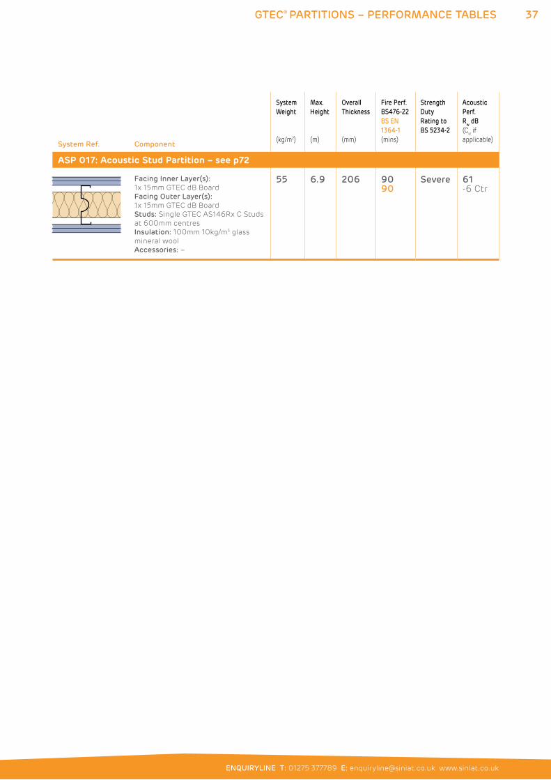
ASP 017: Acoustic Stud Partition – see p72
Facing Inner Layer(s):
1x 15mm GTEC dB Board
Facing Outer Layer(s):
1x 15mm GTEC dB Board
Studs: Single GTEC AS146Rx C Studs
at 600mm centres
Insulation: 100mm 10kg/m3 glass
mineral wool
Accessories: –
55 6.9 206 9090
Severe 61-6 Ctr
38 GTEC® PARTITIONS – PERFORMANCE TABLES
System Ref. Component
System
Weight
(kg/m2)
Max.
Height
(m)
Overall
Thickness
(mm)
Fire Perf.
BS476-22
BS EN
1364-1
(mins)
Strength
Duty
Rating to
BS 5234-2
Acoustic
Perf.
Rw dB
(Ctr if
applicable)
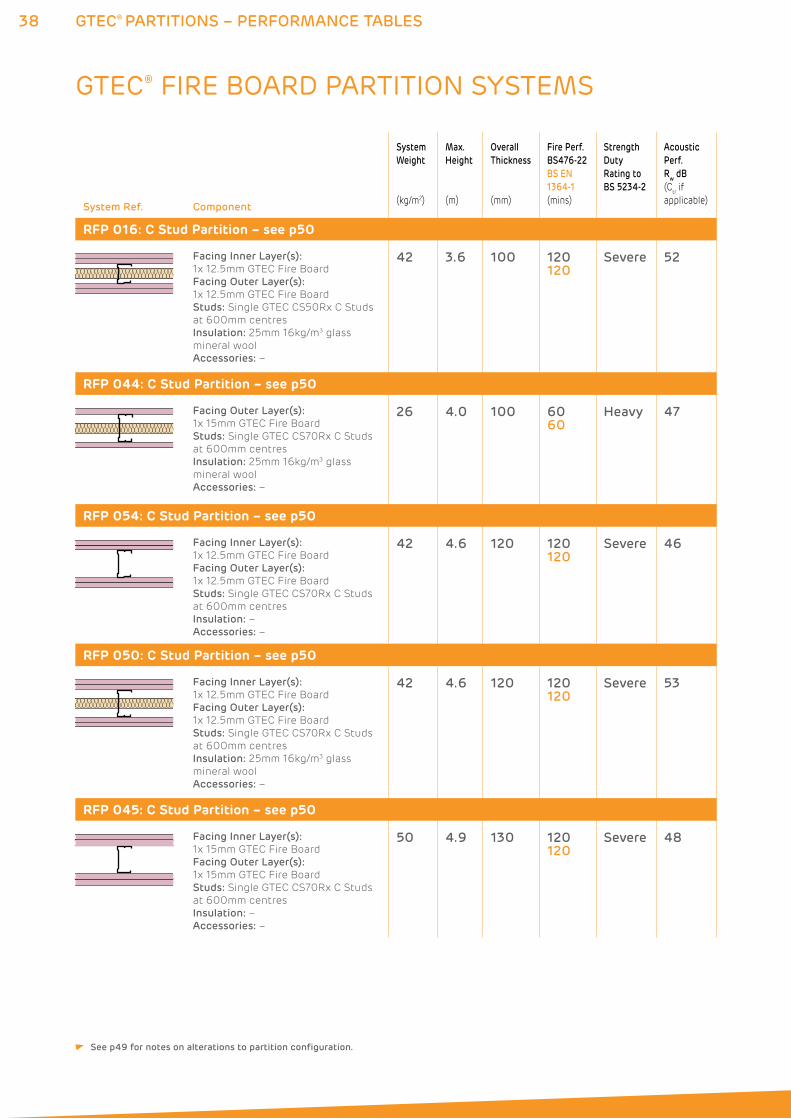
RFP 016: C Stud Partition – see p50
Facing Inner Layer(s):
1x 12.5mm GTEC Fire Board
Facing Outer Layer(s):
1x 12.5mm GTEC Fire Board
Studs: Single GTEC CS50Rx C Studs
at 600mm centres
Insulation: 25mm 16kg/m3 glass
mineral wool
Accessories: –
42 3.6 100 120120
Severe 52
RFP 044: C Stud Partition – see p50
Facing Outer Layer(s):
1x 15mm GTEC Fire Board
Studs: Single GTEC CS70Rx C Studs
at 600mm centres
Insulation: 25mm 16kg/m3 glass
mineral wool
Accessories: –
26 4.0 100 6060
Heavy 47
RFP 054: C Stud Partition – see p50
Facing Inner Layer(s):
1x 12.5mm GTEC Fire Board
Facing Outer Layer(s):
1x 12.5mm GTEC Fire Board
Studs: Single GTEC CS70Rx C Studs
at 600mm centres
Insulation: –
Accessories: –
42 4.6 120 120120
Severe 46
RFP 050: C Stud Partition – see p50
Facing Inner Layer(s):
1x 12.5mm GTEC Fire Board
Facing Outer Layer(s):
1x 12.5mm GTEC Fire Board
Studs: Single GTEC CS70Rx C Studs
at 600mm centres
Insulation: 25mm 16kg/m3 glass
mineral wool
Accessories: –
42 4.6 120 120120
Severe 53
RFP 045: C Stud Partition – see p50
Facing Inner Layer(s):
1x 15mm GTEC Fire Board
Facing Outer Layer(s):
1x 15mm GTEC Fire Board
Studs: Single GTEC CS70Rx C Studs
at 600mm centres
Insulation: –
Accessories: –
50 4.9 130 120120
Severe 48
GTEC® FIRE BOARD PARTITION SYSTEMS
See p49 for notes on alterations to partition configuration.
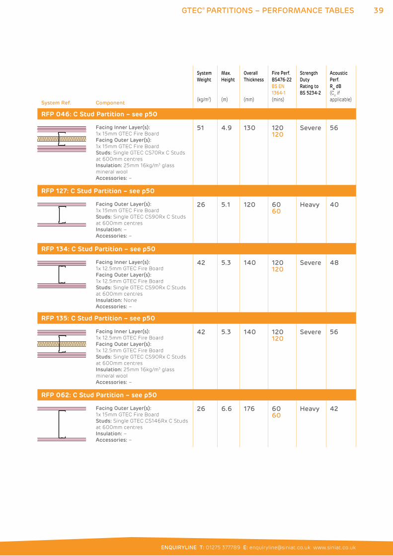
39GTEC® PARTITIONS – PERFORMANCE TABLES
ENQUIRYLINE T: 01275 377789 E: [email protected] www.siniat.co.uk
System Ref. Component
System
Weight
(kg/m2)
Max.
Height
(m)
Overall
Thickness
(mm)
Fire Perf.
BS476-22
BS EN
1364-1
(mins)
Strength
Duty
Rating to
BS 5234-2
Acoustic
Perf.
Rw dB
(Ctr if
applicable)
RFP 046: C Stud Partition – see p50
Facing Inner Layer(s):
1x 15mm GTEC Fire Board
Facing Outer Layer(s):
1x 15mm GTEC Fire Board
Studs: Single GTEC CS70Rx C Studs
at 600mm centres
Insulation: 25mm 16kg/m3 glass
mineral wool
Accessories: –
51 4.9 130 120120
Severe 56
RFP 127: C Stud Partition – see p50
Facing Outer Layer(s):
1x 15mm GTEC Fire Board
Studs: Single GTEC CS90Rx C Studs
at 600mm centres
Insulation: –
Accessories: –
26 5.1 120 6060
Heavy 40
RFP 134: C Stud Partition – see p50
Facing Inner Layer(s):
1x 12.5mm GTEC Fire Board
Facing Outer Layer(s):
1x 12.5mm GTEC Fire Board
Studs: Single GTEC CS90Rx C Studs
at 600mm centres
Insulation: None
Accessories: –
42 5.3 140 120120
Severe 48
RFP 135: C Stud Partition – see p50
Facing Inner Layer(s):
1x 12.5mm GTEC Fire Board
Facing Outer Layer(s):
1x 12.5mm GTEC Fire Board
Studs: Single GTEC CS90Rx C Studs
at 600mm centres
Insulation: 25mm 16kg/m3 glass
mineral wool
Accessories: –
42 5.3 140 120120
Severe 56
RFP 062: C Stud Partition – see p50
Facing Outer Layer(s):
1x 15mm GTEC Fire Board
Studs: Single GTEC CS146Rx C Studs
at 600mm centres
Insulation: –
Accessories: –
26 6.6 176 6060
Heavy 42
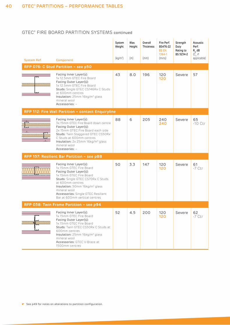
40 GTEC® PARTITIONS – PERFORMANCE TABLES
System Ref. Component
System
Weight
(kg/m2)
Max.
Height
(m)
Overall
Thickness
(mm)
Fire Perf.
BS476-22
BS EN
1364-1
(mins)
Strength
Duty
Rating to
BS 5234-2
Acoustic
Perf.
Rw dB
(Ctr if
applicable)
RFP 076: C Stud Partition – see p50
Facing Inner Layer(s):
1x 12.5mm GTEC Fire Board
Facing Outer Layer(s):
1x 12.5mm GTEC Fire Board
Studs: Single GTEC CS146Rx C Studs
at 600mm centres
Insulation: 25mm 16kg/m3 glass
mineral wool
Accessories: –
43 8.0 196 120120
Severe 57
RFP 112: Fire Wall Partition – contact Enquiryline
Facing Inner Layer(s):
3x 15mm GTEC Fire Board down centre
Facing Outer Layer(s):
2x 15mm GTEC Fire Board each side
Studs: Twin Staggered GTEC CS50Rx
C Studs at 600mm centres
Insulation: 2x 25mm 16kg/m3 glass
mineral wool
Accessories: –
88 6 205 240240
Severe 65 -10 Ctr
RFP 157: Resilient Bar Partition – see p88
Facing Inner Layer(s):
1x 15mm GTEC Fire Board
Facing Outer Layer(s):
1x 15mm GTEC Fire Board
Studs: Single GTEC CS70Rx C Studs
at 600mm centres
Insulation: 50mm 16kg/m3 glass
mineral wool
Accessories: Single GTEC Resilient
Bar at 600mm vertical centres
50 3.3 147 120120
Severe 61-7 Ctr
RFP 038: Twin Frame Partition – see p94
Facing Inner Layer(s):
1x 15mm GTEC Fire Board
Facing Outer Layer(s):
1x 15mm GTEC Fire Board
Studs: Twin GTEC CS50Rx C Studs at
600mm centres
Insulation: 25mm 16kg/m3 glass
mineral wool
Accessories: GTEC V-Brace at
1500mm centres
52 4.5 200 120120
Severe 62-7 Ctr
GTEC® FIRE BOARD PARTITION SYSTEMS continued
See p49 for notes on alterations to partition configuration.
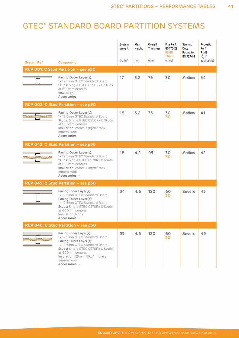
41GTEC® PARTITIONS – PERFORMANCE TABLES
ENQUIRYLINE T: 01275 377789 E: [email protected] www.siniat.co.uk
System Ref. Component
System
Weight
(kg/m2)
Max.
Height
(m)
Overall
Thickness
(mm)
Fire Perf.
BS476-22
BS EN
1364-1
(mins)
Strength
Duty
Rating to
BS 5234-2
Acoustic
Perf.
Rw dB
(Ctr if
applicable)
RCP 001: C Stud Partition – see p50
Facing Outer Layer(s):
1x 12.5mm GTEC Standard Board
Studs: Single GTEC CS50Rx C Studs
at 600mm centres
Insulation: –
Accessories: –
17 3.2 75 30–
Medium 34
RCP 002: C Stud Partition – see p50
Facing Outer Layer(s):
1x 12.5mm GTEC Standard Board
Studs: Single GTEC CS50Rx C Studs
at 600mm centres
Insulation: 25mm 33kg/m3 rock
mineral wool
Accessories: –
18 3.2 75 3030
Medium 41
RCP 042: C Stud Partition – see p50
Facing Outer Layer(s):
1x 12.5mm GTEC Standard Board
Studs: Single GTEC CS70Rx C Studs
at 600mm centres
Insulation: 25mm 33kg/m3 rock
mineral wool
Accessories: –
18 4.2 95 3030
Medium 42
RCP 045: C Stud Partition – see p50
Facing Inner Layer(s):
1x 12.5mm GTEC Standard Board
Facing Outer Layer(s):
1x 12.5mm GTEC Standard Board
Studs: Single GTEC CS70Rx C Studs
at 600mm centres
Insulation: None
Accessories: –
34 4.6 120 6030
Severe 45
RCP 046: C Stud Partition – see p50
Facing Inner Layer(s):
1x 12.5mm GTEC Standard Board
Facing Outer Layer(s):
1x 12.5mm GTEC Standard Board
Studs: Single GTEC CS70Rx C Studs
at 600mm centres
Insulation: 25mm 16kg/m3 glass
mineral wool
Accessories: –
35 4.6 120 6030
Severe 49
GTEC® STANDARD BOARD PARTITION SYSTEMS
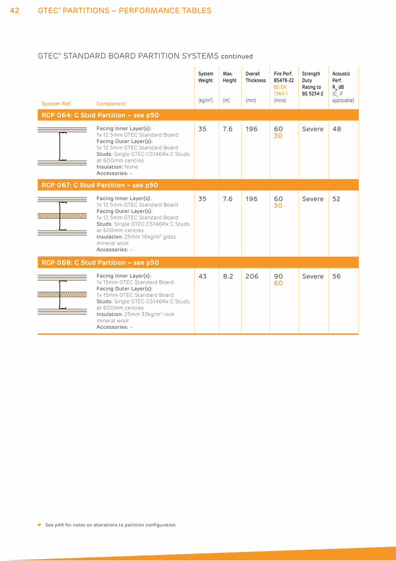
42 GTEC® PARTITIONS – PERFORMANCE TABLES
System Ref. Component
System
Weight
(kg/m2)
Max.
Height
(m)
Overall
Thickness
(mm)
Fire Perf.
BS476-22
BS EN
1364-1
(mins)
Strength
Duty
Rating to
BS 5234-2
Acoustic
Perf.
Rw dB
(Ctr if
applicable)
RCP 064: C Stud Partition – see p50
Facing Inner Layer(s):
1x 12.5mm GTEC Standard Board
Facing Outer Layer(s):
1x 12.5mm GTEC Standard Board
Studs: Single GTEC CS146Rx C Studs
at 600mm centres
Insulation: None
Accessories: –
35 7.6 196 6030
Severe 48
RCP 067: C Stud Partition – see p50
Facing Inner Layer(s):
1x 12.5mm GTEC Standard Board
Facing Outer Layer(s):
1x 12.5mm GTEC Standard Board
Studs: Single GTEC CS146Rx C Studs
at 600mm centres
Insulation: 25mm 16kg/m3 glass
mineral wool
Accessories: –
35 7.6 196 6030
Severe 52
RCP 068: C Stud Partition – see p50
Facing Inner Layer(s):
1x 15mm GTEC Standard Board
Facing Outer Layer(s):
1x 15mm GTEC Standard Board
Studs: Single GTEC CS146Rx C Studs
at 600mm centres
Insulation: 25mm 33kg/m3 rock
mineral wool
Accessories: –
43 8.2 206 9060
Severe 56
GTEC® STANDARD BOARD PARTITION SYSTEMS continued
See p49 for notes on alterations to partition configuration.
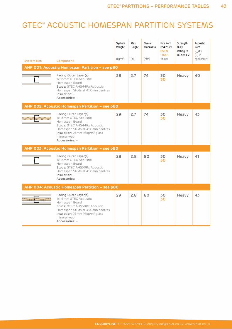
43GTEC® PARTITIONS – PERFORMANCE TABLES
ENQUIRYLINE T: 01275 377789 E: [email protected] www.siniat.co.uk
System Ref. Component
System
Weight
(kg/m2)
Max.
Height
(m)
Overall
Thickness
(mm)
Fire Perf.
BS476-22
BS EN
1364-1
(mins)
Strength
Duty
Rating to
BS 5234-2
Acoustic
Perf.
Rw dB
(Ctr if
applicable)
AHP 001: Acoustic Homespan Partition – see p80
Facing Outer Layer(s):
1x 15mm GTEC Acoustic
Homespan Board
Studs: GTEC AHS44Rx Acoustic
Homespan Studs at 450mm centres
Insulation: –
Accessories: –
28 2.7 74 3030
Heavy 40
AHP 002: Acoustic Homespan Partition – see p80
Facing Outer Layer(s):
1x 15mm GTEC Acoustic
Homespan Board
Studs: GTEC AHS44Rx Acoustic
Homespan Studs at 450mm centres
Insulation: 25mm 16kg/m3 glass
mineral wool
Accessories: –
29 2.7 74 3030
Heavy 43
AHP 003: Acoustic Homespan Partition – see p80
Facing Outer Layer(s):
1x 15mm GTEC Acoustic
Homespan Board
Studs: GTEC AHS50Rx Acoustic
Homespan Studs at 450mm centres
Insulation: –
Accessories: –
28 2.8 80 3030
Heavy 41
AHP 004: Acoustic Homespan Partition – see p80
Facing Outer Layer(s):
1x 15mm GTEC Acoustic
Homespan Board
Studs: GTEC AHS50Rx Acoustic
Homespan Studs at 450mm centres
Insulation: 25mm 16kg/m3 glass
mineral wool
Accessories: –
29 2.8 80 3030
Heavy 43
GTEC® ACOUSTIC HOMESPAN PARTITION SYSTEMS
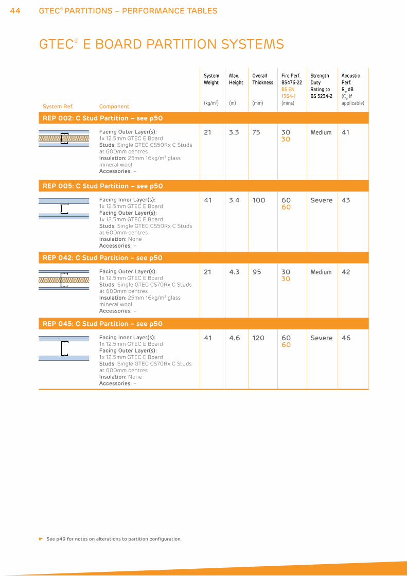
44 GTEC® PARTITIONS – PERFORMANCE TABLES
System Ref. Component
System
Weight
(kg/m2)
Max.
Height
(m)
Overall
Thickness
(mm)
Fire Perf.
BS476-22
BS EN
1364-1
(mins)
Strength
Duty
Rating to
BS 5234-2
Acoustic
Perf.
Rw dB
(Ctr if
applicable)
REP 002: C Stud Partition – see p50
Facing Outer Layer(s):
1x 12.5mm GTEC E Board
Studs: Single GTEC CS50Rx C Studs
at 600mm centres
Insulation: 25mm 16kg/m3 glass
mineral wool
Accessories: –
21 3.3 75 3030
Medium 41
REP 005: C Stud Partition – see p50
Facing Inner Layer(s):
1x 12.5mm GTEC E Board
Facing Outer Layer(s):
1x 12.5mm GTEC E Board
Studs: Single GTEC CS50Rx C Studs
at 600mm centres
Insulation: None
Accessories: –
41 3.4 100 6060
Severe 43
REP 042: C Stud Partition – see p50
Facing Outer Layer(s):
1x 12.5mm GTEC E Board
Studs: Single GTEC CS70Rx C Studs
at 600mm centres
Insulation: 25mm 16kg/m3 glass
mineral wool
Accessories: –
21 4.3 95 3030
Medium 42
REP 045: C Stud Partition – see p50
Facing Inner Layer(s):
1x 12.5mm GTEC E Board
Facing Outer Layer(s):
1x 12.5mm GTEC E Board
Studs: Single GTEC CS70Rx C Studs
at 600mm centres
Insulation: None
Accessories: –
41 4.6 120 6060
Severe 46
GTEC® E BOARD PARTITION SYSTEMS
See p49 for notes on alterations to partition configuration.
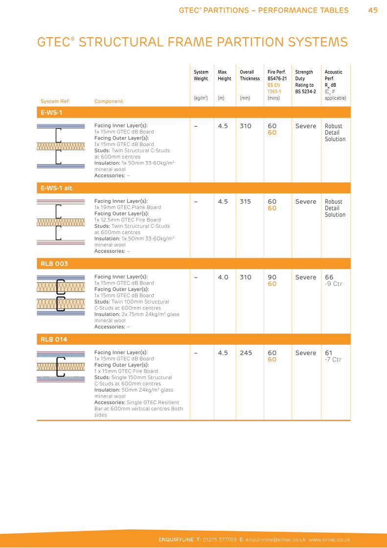
45GTEC® PARTITIONS – PERFORMANCE TABLES
ENQUIRYLINE T: 01275 377789 E: [email protected] www.siniat.co.uk
System Ref. Component
System
Weight
(kg/m2)
Max.
Height
(m)
Overall
Thickness
(mm)
Fire Perf.
BS476-21
BS EN
1365-1
(mins)
Strength
Duty
Rating to
BS 5234-2
Acoustic
Perf.
Rw dB
(Ctr if
applicable)
E-WS-1
Facing Inner Layer(s):
1x 15mm GTEC dB Board
Facing Outer Layer(s):
1x 15mm GTEC dB Board
Studs: Twin Structural C-Studs
at 600mm centres
Insulation: 1x 50mm 33-60kg/m3
mineral wool
Accessories: –
– 4.5 310 6060
Severe Robust Detail Solution
E-WS-1 alt.
Facing Inner Layer(s):
1x 19mm GTEC Plank Board
Facing Outer Layer(s):
1x 12.5mm GTEC Fire Board
Studs: Twin Structural C-Studs
at 600mm centres
Insulation: 1x 50mm 33-60kg/m3
mineral wool
Accessories: –
– 4.5 315 6060
Severe Robust Detail Solution
RLB 003
Facing Inner Layer(s):
1x 15mm GTEC dB Board
Facing Outer Layer(s):
1x 15mm GTEC dB Board
Studs: Twin 100mm Structural
C-Studs at 600mm centres
Insulation: 2x 75mm 24kg/m3 glass
mineral wool
Accessories: –
– 4.0 310 9060
Severe 66 -9 Ctr
RLB 014
Facing Inner Layer(s):
1x 15mm GTEC dB Board
Facing Outer Layer(s):
1 x 15mm GTEC Fire Board
Studs: Single 150mm Structural
C-Studs at 600mm centres
Insulation: 50mm 24kg/m3 glass
mineral wool
Accessories: Single GTEC Resilient
Bar at 600mm vertical centres Both
sides
– 4.5 245 6060
Severe 61 -7 Ctr
GTEC® STRUCTURAL FRAME PARTITION SYSTEMS
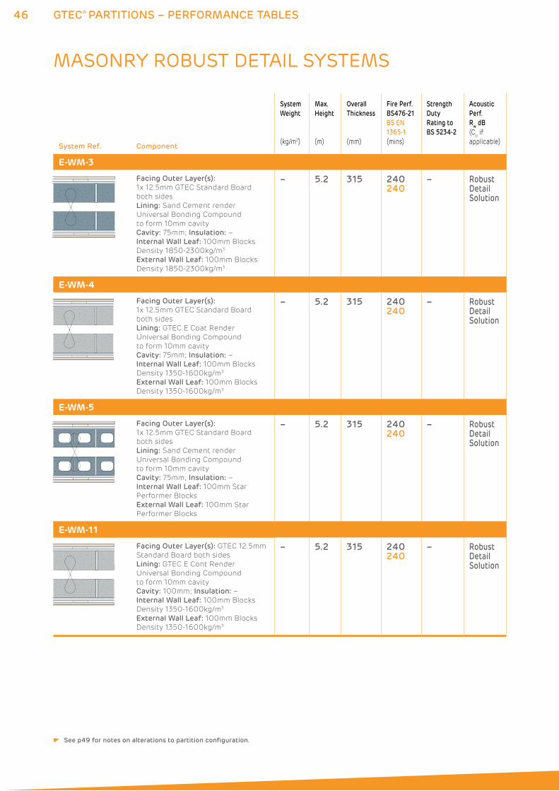
46 GTEC® PARTITIONS – PERFORMANCE TABLES
System Ref. Component
System
Weight
(kg/m2)
Max.
Height
(m)
Overall
Thickness
(mm)
Fire Perf.
BS476-21
BS EN
1365-1
(mins)
Strength
Duty
Rating to
BS 5234-2
Acoustic
Perf.
Rw dB
(Ctr if
applicable)
E-WM-3
Facing Outer Layer(s):
1x 12.5mm GTEC Standard Board
both sides
Lining: Sand Cement render
Universal Bonding Compound
to form 10mm cavity
Cavity: 75mm; Insulation: –
Internal Wall Leaf: 100mm Blocks
Density 1850-2300kg/m3
External Wall Leaf: 100mm Blocks
Density 1850-2300kg/m3
– 5.2 315 240240
– Robust Detail Solution
E-WM-4
Facing Outer Layer(s):
1x 12.5mm GTEC Standard Board
both sides
Lining: GTEC E Coat Render
Universal Bonding Compound
to form 10mm cavity
Cavity: 75mm; Insulation: –
Internal Wall Leaf: 100mm Blocks
Density 1350-1600kg/m3
External Wall Leaf: 100mm Blocks
Density 1350-1600kg/m3
– 5.2 315 240240
– Robust Detail Solution
E-WM-5
Facing Outer Layer(s):
1x 12.5mm GTEC Standard Board
both sides
Lining: Sand Cement render
Universal Bonding Compound
to form 10mm cavity
Cavity: 75mm; Insulation: –
Internal Wall Leaf: 100mm Star
Performer Blocks
External Wall Leaf: 100mm Star
Performer Blocks
– 5.2 315 240240
– Robust Detail Solution
E-WM-11
Facing Outer Layer(s): GTEC 12.5mm
Standard Board both sides
Lining: GTEC E Cont Render
Universal Bonding Compound
to form 10mm cavity
Cavity: 100mm; Insulation: –
Internal Wall Leaf: 100mm Blocks
Density 1350-1600kg/m3
External Wall Leaf: 100mm Blocks
Density 1350-1600kg/m3
– 5.2 315 240240
– Robust Detail Solution
MASONRY ROBUST DETAIL SYSTEMS
See p49 for notes on alterations to partition configuration.
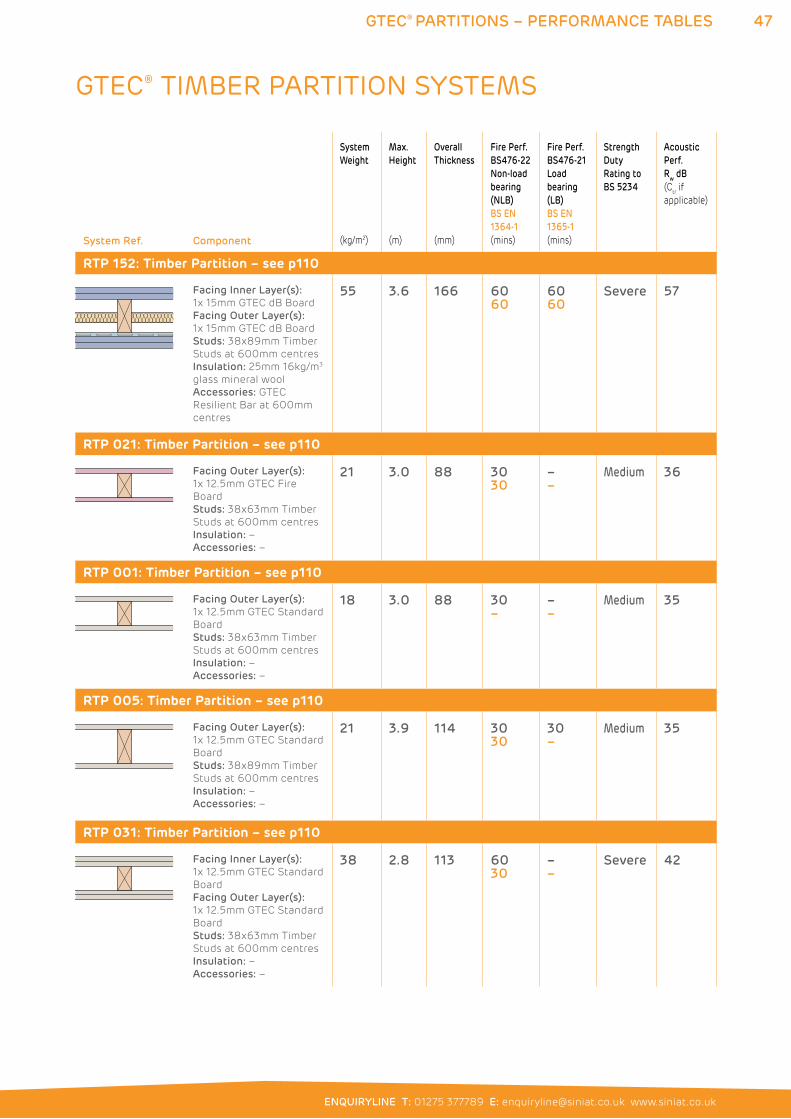
47GTEC® PARTITIONS – PERFORMANCE TABLES
ENQUIRYLINE T: 01275 377789 E: [email protected] www.siniat.co.uk
System Ref. Component
System
Weight
(kg/m2)
Max.
Height
(m)
Overall
Thickness
(mm)
Fire Perf.
BS476-22
Non-load
bearing
(NLB)
BS EN
1364-1
(mins)
Fire Perf.
BS476-21
Load
bearing
(LB)
BS EN
1365-1
(mins)
Strength
Duty
Rating to
BS 5234
Acoustic
Perf.
Rw dB
(Ctr if
applicable)
RTP 152: Timber Partition – see p110
Facing Inner Layer(s):
1x 15mm GTEC dB Board
Facing Outer Layer(s):
1x 15mm GTEC dB Board
Studs: 38x89mm Timber
Studs at 600mm centres
Insulation: 25mm 16kg/m3
glass mineral wool
Accessories: GTEC
Resilient Bar at 600mm
centres
55 3.6 166 6060
6060
Severe 57
RTP 021: Timber Partition – see p110
Facing Outer Layer(s):
1x 12.5mm GTEC Fire
Board
Studs: 38x63mm Timber
Studs at 600mm centres
Insulation: –
Accessories: –
21 3.0 88 3030
––
Medium 36
RTP 001: Timber Partition – see p110
Facing Outer Layer(s):
1x 12.5mm GTEC Standard
Board
Studs: 38x63mm Timber
Studs at 600mm centres
Insulation: –
Accessories: –
18 3.0 88 30–
––
Medium 35
RTP 005: Timber Partition – see p110
Facing Outer Layer(s):
1x 12.5mm GTEC Standard
Board
Studs: 38x89mm Timber
Studs at 600mm centres
Insulation: –
Accessories: –
21 3.9 114 3030
30–
Medium 35
RTP 031: Timber Partition – see p110
Facing Inner Layer(s):
1x 12.5mm GTEC Standard
Board
Facing Outer Layer(s):
1x 12.5mm GTEC Standard
Board
Studs: 38x63mm Timber
Studs at 600mm centres
Insulation: –
Accessories: –
38 2.8 113 6030
––
Severe 42
GTEC® TIMBER PARTITION SYSTEMS
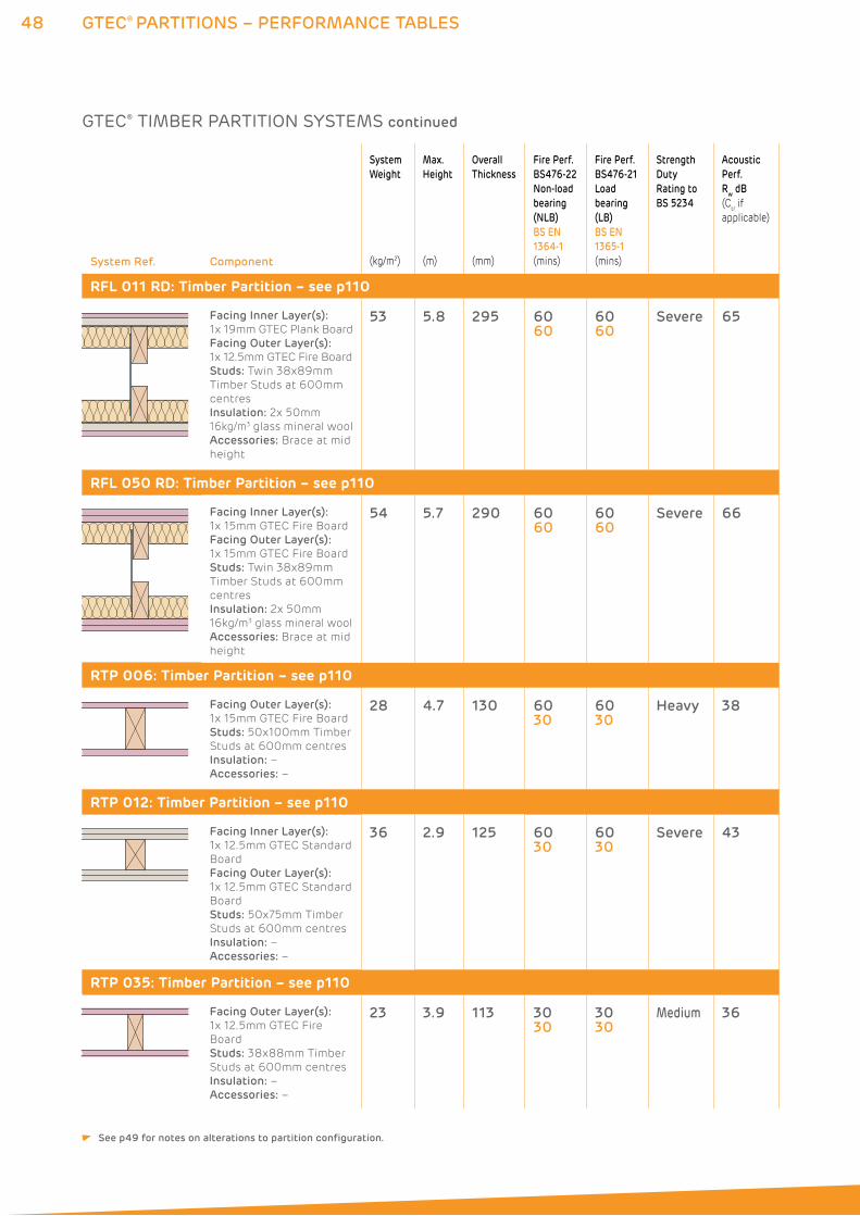
48 GTEC® PARTITIONS – PERFORMANCE TABLES
System Ref. Component
System
Weight
(kg/m2)
Max.
Height
(m)
Overall
Thickness
(mm)
Fire Perf.
BS476-22
Non-load
bearing
(NLB)
BS EN
1364-1
(mins)
Fire Perf.
BS476-21
Load
bearing
(LB)
BS EN
1365-1
(mins)
Strength
Duty
Rating to
BS 5234
Acoustic
Perf.
Rw dB
(Ctr if
applicable)
RFL 011 RD: Timber Partition – see p110
Facing Inner Layer(s):
1x 19mm GTEC Plank Board
Facing Outer Layer(s):
1x 12.5mm GTEC Fire Board
Studs: Twin 38x89mm
Timber Studs at 600mm
centres
Insulation: 2x 50mm
16kg/m3 glass mineral wool
Accessories: Brace at mid
height
53 5.8 295 6060
6060
Severe 65
RFL 050 RD: Timber Partition – see p110
Facing Inner Layer(s):
1x 15mm GTEC Fire Board
Facing Outer Layer(s):
1x 15mm GTEC Fire Board
Studs: Twin 38x89mm
Timber Studs at 600mm
centres
Insulation: 2x 50mm
16kg/m3 glass mineral wool
Accessories: Brace at mid
height
54 5.7 290 6060
6060
Severe 66
RTP 006: Timber Partition – see p110
Facing Outer Layer(s):
1x 15mm GTEC Fire Board
Studs: 50x100mm Timber
Studs at 600mm centres
Insulation: –
Accessories: –
28 4.7 130 6030
6030
Heavy 38
RTP 012: Timber Partition – see p110
Facing Inner Layer(s):
1x 12.5mm GTEC Standard
Board
Facing Outer Layer(s):
1x 12.5mm GTEC Standard
Board
Studs: 50x75mm Timber
Studs at 600mm centres
Insulation: –
Accessories: –
36 2.9 125 6030
6030
Severe 43
RTP 035: Timber Partition – see p110
Facing Outer Layer(s):
1x 12.5mm GTEC Fire
Board
Studs: 38x88mm Timber
Studs at 600mm centres
Insulation: –
Accessories: –
23 3.9 113 3030
3030
Medium 36
GTEC® TIMBER PARTITION SYSTEMS continued
See p49 for notes on alterations to partition configuration.
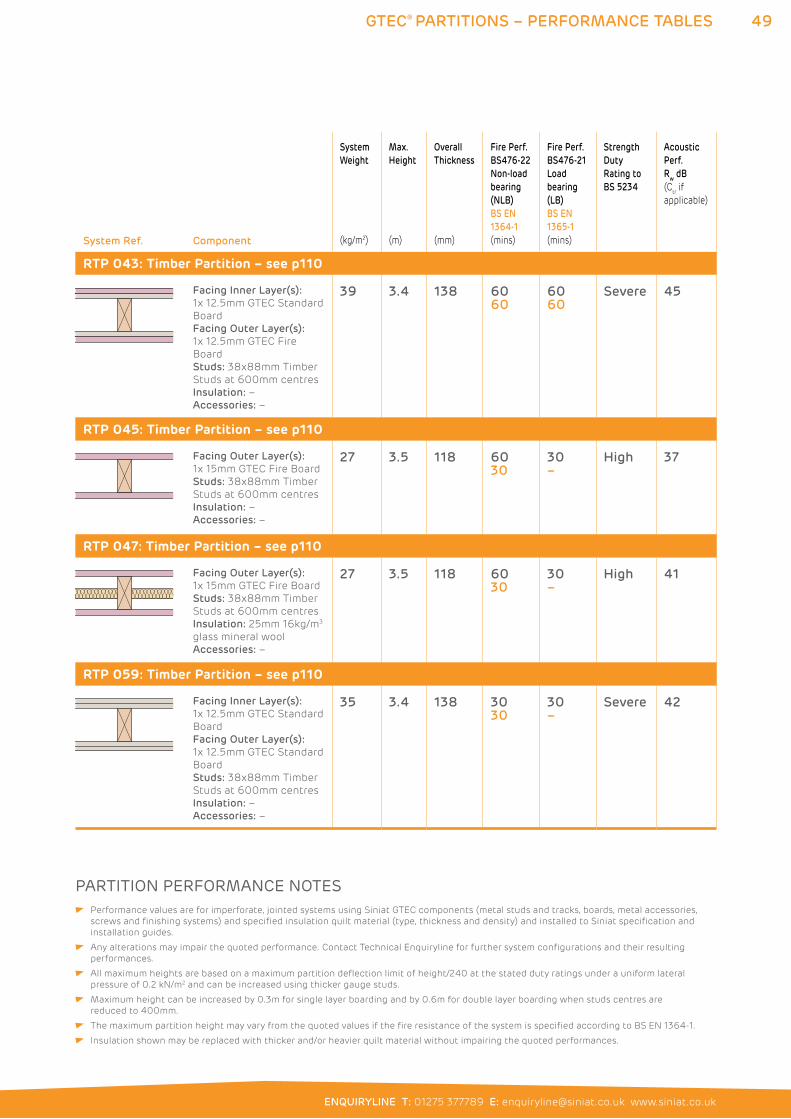
49GTEC® PARTITIONS – PERFORMANCE TABLES
ENQUIRYLINE T: 01275 377789 E: [email protected] www.siniat.co.uk
System Ref. Component
System
Weight
(kg/m2)
Max.
Height
(m)
Overall
Thickness
(mm)
Fire Perf.
BS476-22
Non-load
bearing
(NLB)
BS EN
1364-1
(mins)
Fire Perf.
BS476-21
Load
bearing
(LB)
BS EN
1365-1
(mins)
Strength
Duty
Rating to
BS 5234
Acoustic
Perf.
Rw dB
(Ctr if
applicable)
RTP 043: Timber Partition – see p110
Facing Inner Layer(s):
1x 12.5mm GTEC Standard
Board
Facing Outer Layer(s):
1x 12.5mm GTEC Fire
Board
Studs: 38x88mm Timber
Studs at 600mm centres
Insulation: –
Accessories: –
39 3.4 138 6060
6060
Severe 45
RTP 045: Timber Partition – see p110
Facing Outer Layer(s):
1x 15mm GTEC Fire Board
Studs: 38x88mm Timber
Studs at 600mm centres
Insulation: –
Accessories: –
27 3.5 118 6030
30–
High 37
RTP 047: Timber Partition – see p110
Facing Outer Layer(s):
1x 15mm GTEC Fire Board
Studs: 38x88mm Timber
Studs at 600mm centres
Insulation: 25mm 16kg/m3
glass mineral wool
Accessories: –
27 3.5 118 6030
30–
High 41
RTP 059: Timber Partition – see p110
Facing Inner Layer(s):
1x 12.5mm GTEC Standard
Board
Facing Outer Layer(s):
1x 12.5mm GTEC Standard
Board
Studs: 38x88mm Timber
Studs at 600mm centres
Insulation: –
Accessories: –
35 3.4 138 3030
30–
Severe 42
PARTITION PERFORMANCE NOTES Performance values are for imperforate, jointed systems using Siniat GTEC components (metal studs and tracks, boards, metal accessories,
screws and finishing systems) and specified insulation quilt material (type, thickness and density) and installed to Siniat specification and
installation guides.
Any alterations may impair the quoted performance. Contact Technical Enquiryline for further system configurations and their resulting
performances.
All maximum heights are based on a maximum partition deflection limit of height/240 at the stated duty ratings under a uniform lateral
pressure of 0.2 kN/m2 and can be increased using thicker gauge studs.
Maximum height can be increased by 0.3m for single layer boarding and by 0.6m for double layer boarding when studs centres are
reduced to 400mm.
The maximum partition height may vary from the quoted values if the fire resistance of the system is specified according to BS EN 1364-1.
Insulation shown may be replaced with thicker and/or heavier quilt material without impairing the quoted performances.
50 GTEC® C STUD PARTITION
GTEC® C STUD PARTITION SYSTEMSGTEC Metal Stud Partitioning is an economical, friction-fit system for
assembling internal partitions. The unique design of the components
ensures high strength, easy installation and a higher performing
alternative to traditional timber frame partitions.
GTEC C Stud Partitions are constructed using a frame of GTEC U Track
at the head and base with GTEC C Studs for vertical framing elements.
A range of GTEC C Stud and U Track widths allow varying partition
depth, enhancing fire resistance, sound insulation and maximum
heights. For individual system performances, refer to the System
Performance Tables on pages 22 to 44.
WHERE TO USE: GTEC C Stud Partitions create internal dividing walls within both
domestic and commercial projects.
FEATURES BENEFITS
Strong Less material is required than a similar timber
frame structure
Lightweight Multiple lengths can be carried at one time
Natural resistance to bowing, bending and
insect infestation
Metal maintains shape, removing the chance of
‘screw popping’
High fire resistance levels Fire performance levels are easily achieved
using metal
High acoustic performance levels Acoustic performance levels are easily achieved
using metal
Flat finish Provides an easy surface for decoration
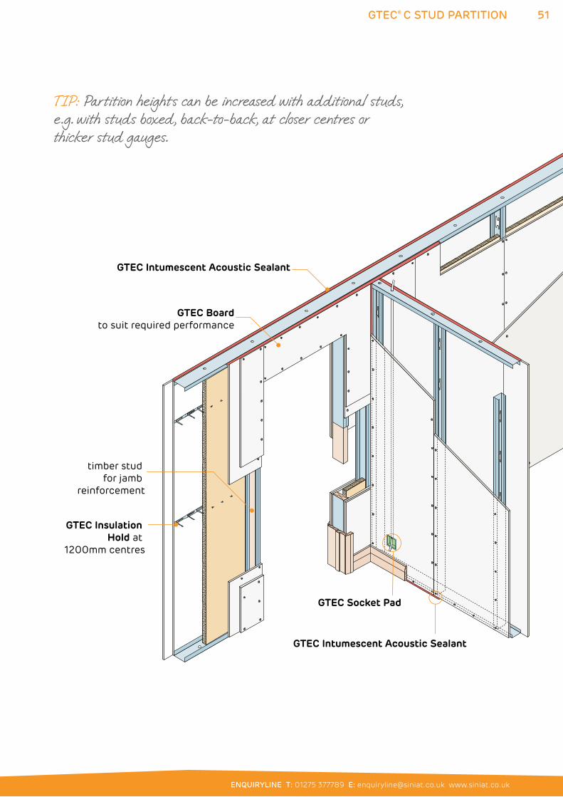
51
ENQUIRYLINE T: 01275 377789 E: [email protected] www.siniat.co.uk
GTEC® C STUD PARTITION
GTEC Intumescent Acoustic Sealant
GTEC Socket Pad
GTEC Boardto suit required performance
GTEC Intumescent Acoustic Sealant
GTEC Insulation Hold at
1200mm centres
timber stud for jamb
reinforcement
TIP: Partition heights can be increased with additional studs, e.g. with studs boxed, back-to-back, at closer centres or thicker stud gauges.
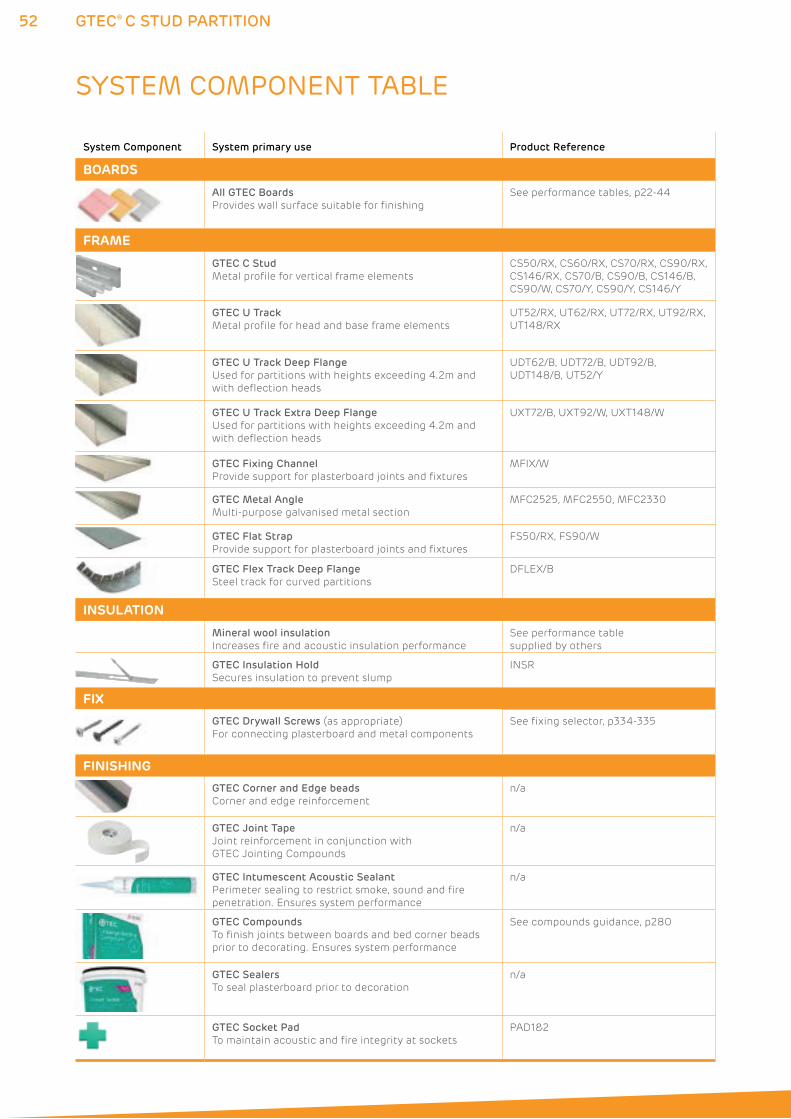
52 GTEC® C STUD PARTITION
SYSTEM COMPONENT TABLE
System Component System primary use Product Reference
BOARDS
All GTEC Boards
Provides wall surface suitable for finishing
See performance tables, p22-44
FRAME
GTEC C Stud
Metal profile for vertical frame elements
CS50/RX, CS60/RX, CS70/RX, CS90/RX,
CS146/RX, CS70/B, CS90/B, CS146/B,
CS90/W, CS70/Y, CS90/Y, CS146/Y
GTEC U Track
Metal profile for head and base frame elements
UT52/RX, UT62/RX, UT72/RX, UT92/RX,
UT148/RX
GTEC U Track Deep Flange
Used for partitions with heights exceeding 4.2m and
with deflection heads
UDT62/B, UDT72/B, UDT92/B,
UDT148/B, UT52/Y
GTEC U Track Extra Deep Flange
Used for partitions with heights exceeding 4.2m and
with deflection heads
UXT72/B, UXT92/W, UXT148/W
GTEC Fixing Channel
Provide support for plasterboard joints and fixtures
MFIX/W
GTEC Metal Angle
Multi-purpose galvanised metal section
MFC2525, MFC2550, MFC2330
GTEC Flat Strap
Provide support for plasterboard joints and fixtures
FS50/RX, FS90/W
GTEC Flex Track Deep Flange
Steel track for curved partitions
DFLEX/B
INSULATION
Mineral wool insulation
Increases fire and acoustic insulation performance
See performance table
supplied by others
GTEC Insulation Hold
Secures insulation to prevent slump
INSR
FIX
GTEC Drywall Screws (as appropriate)
For connecting plasterboard and metal components
See fixing selector, p334-335
FINISHING
GTEC Corner and Edge beads
Corner and edge reinforcement
n/a
GTEC Joint Tape
Joint reinforcement in conjunction with
GTEC Jointing Compounds
n/a
GTEC Intumescent Acoustic Sealant
Perimeter sealing to restrict smoke, sound and fire
penetration. Ensures system performance
n/a
GTEC Compounds
To finish joints between boards and bed corner beads
prior to decorating. Ensures system performance
See compounds guidance, p280
GTEC Sealers
To seal plasterboard prior to decoration
n/a
GTEC Socket Pad
To maintain acoustic and fire integrity at sockets
PAD1&2
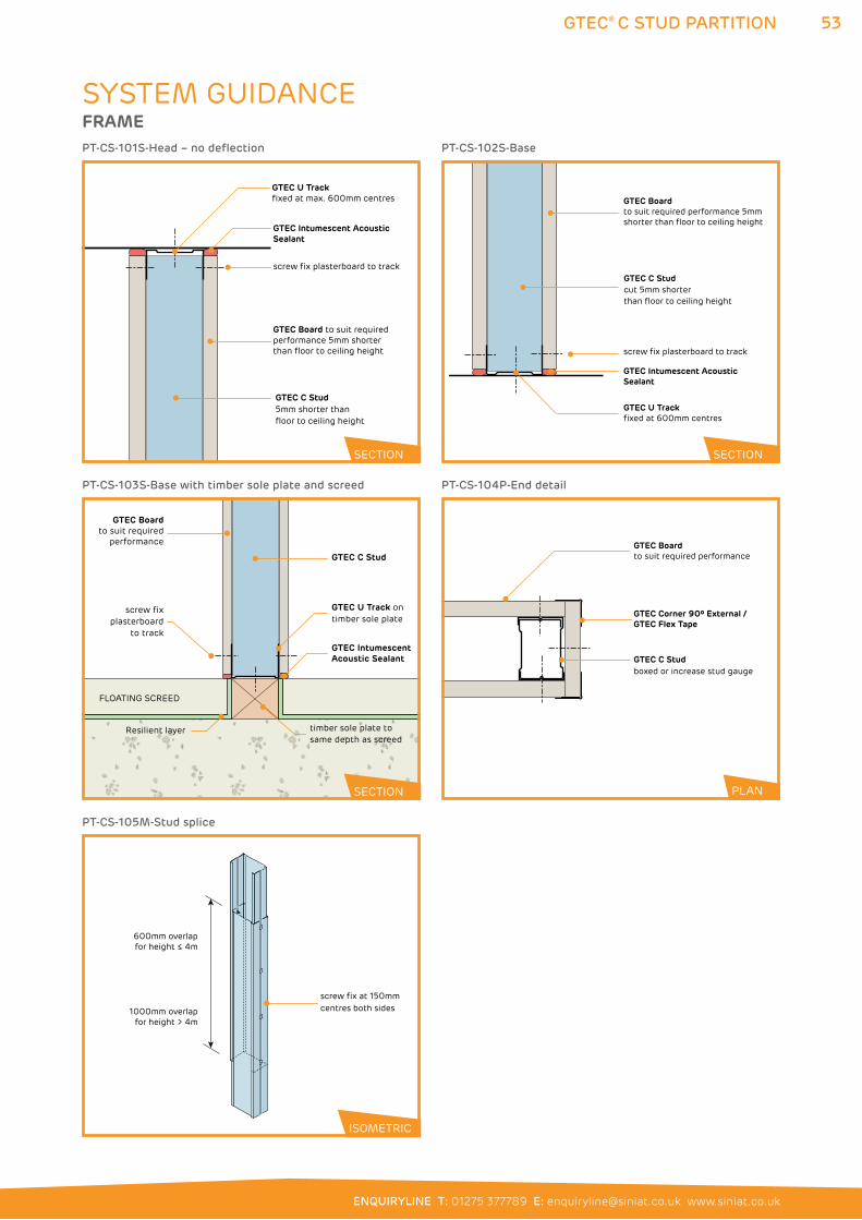
53
ENQUIRYLINE T: 01275 377789 E: [email protected] www.siniat.co.uk
GTEC® C STUD PARTITION
GTEC U Track fixed at max. 600mm centres
GTEC Intumescent AcousticSealant
GTEC Board to suit requiredperformance 5mm shorter than floor to ceiling height
GTEC C Stud5mm shorter than floor to ceiling height
screw fix plasterboard to track
600mm overlapfor height ≤ 4m
1000mm overlapfor height > 4m
screw fix at 150mm centres both sides
GTEC U Track fixed at 600mm centres
GTEC Intumescent AcousticSealant
GTEC C Stud cut 5mm shorter than floor to ceiling height
screw fix plasterboard to track
GTEC Boardto suit required performance 5mm shorter than floor to ceiling height
PT-CS-101S-Head – no deflection
PT-CS-105M-Stud splice
GTEC Intumescent Acoustic Sealant
GTEC Boardto suit required
performance
GTEC C Stud
screw fix plasterboard
to track
GTEC U Track ontimber sole plate
FLOATING SCREED
Resilient layer timber sole plate to same depth as screed
PT-CS-103S-Base with timber sole plate and screed
GTEC C Studboxed or increase stud gauge
GTEC Boardto suit required performance
GTEC Corner 90º External /GTEC Flex Tape
PT-CS-104P-End detail
PT-CS-102S-Base
PLAN
SECTION
SECTION
SECTION
ISOMETRIC
SYSTEM GUIDANCEFRAME
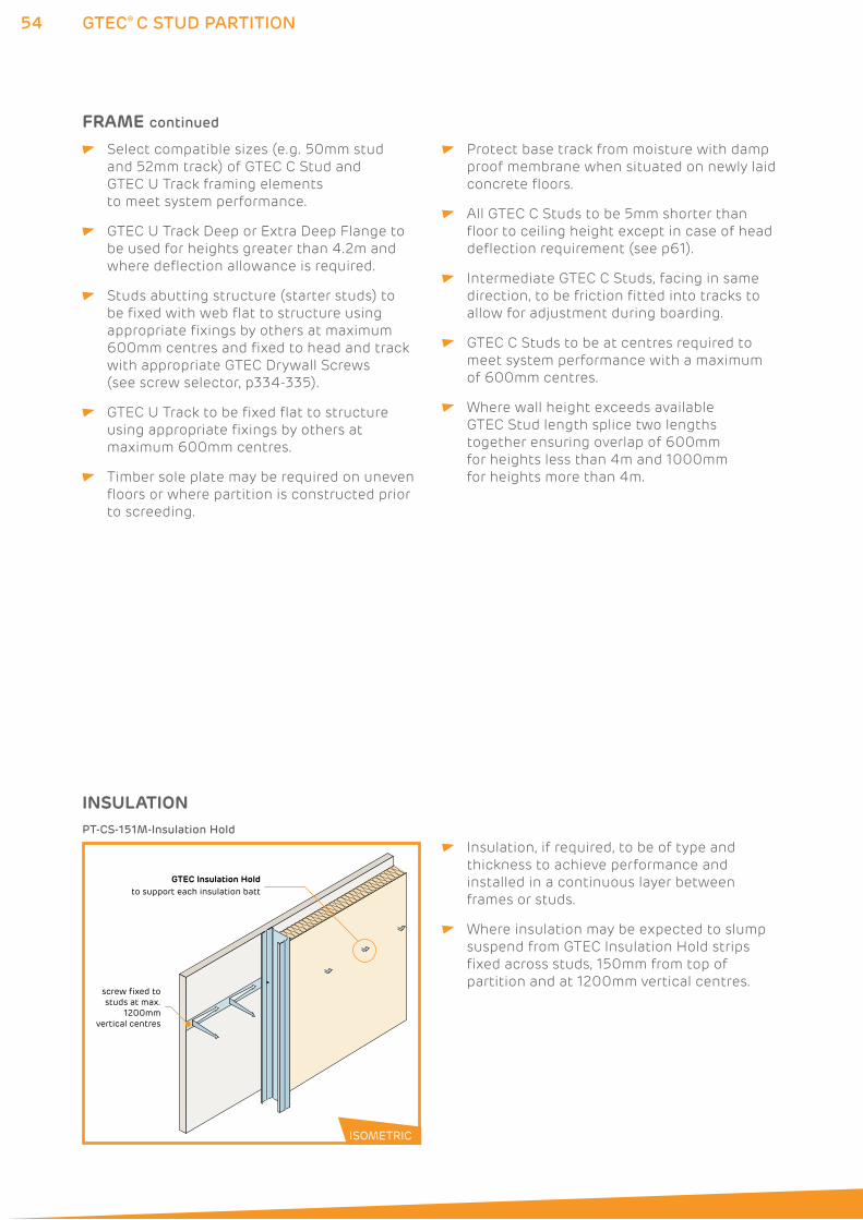
54
Insulation, if required, to be of type and
thickness to achieve performance and
installed in a continuous layer between
frames or studs.
Where insulation may be expected to slump
suspend from GTEC Insulation Hold strips
fixed across studs, 150mm from top of
partition and at 1200mm vertical centres.
GTEC® C STUD PARTITION
Select compatible sizes (e.g. 50mm stud
and 52mm track) of GTEC C Stud and
GTEC U Track framing elements
to meet system performance.
GTEC U Track Deep or Extra Deep Flange to
be used for heights greater than 4.2m and
where deflection allowance is required.
Studs abutting structure (starter studs) to
be fixed with web flat to structure using
appropriate fixings by others at maximum
600mm centres and fixed to head and track
with appropriate GTEC Drywall Screws
(see screw selector, p334-335).
GTEC U Track to be fixed flat to structure
using appropriate fixings by others at
maximum 600mm centres.
Timber sole plate may be required on uneven
floors or where partition is constructed prior
to screeding.
Protect base track from moisture with damp
proof membrane when situated on newly laid
concrete floors.
All GTEC C Studs to be 5mm shorter than
floor to ceiling height except in case of head
deflection requirement (see p61).
Intermediate GTEC C Studs, facing in same
direction, to be friction fitted into tracks to
allow for adjustment during boarding.
GTEC C Studs to be at centres required to
meet system performance with a maximum
of 600mm centres.
Where wall height exceeds available
GTEC Stud length splice two lengths
together ensuring overlap of 600mm
for heights less than 4m and 1000mm
for heights more than 4m.
GTEC Insulation Holdto support each insulation batt
screw fixed to studs at max.
1200mm vertical centres
PT-CS-151M-Insulation Hold
ISOMETRIC
INSULATION
FRAME continued
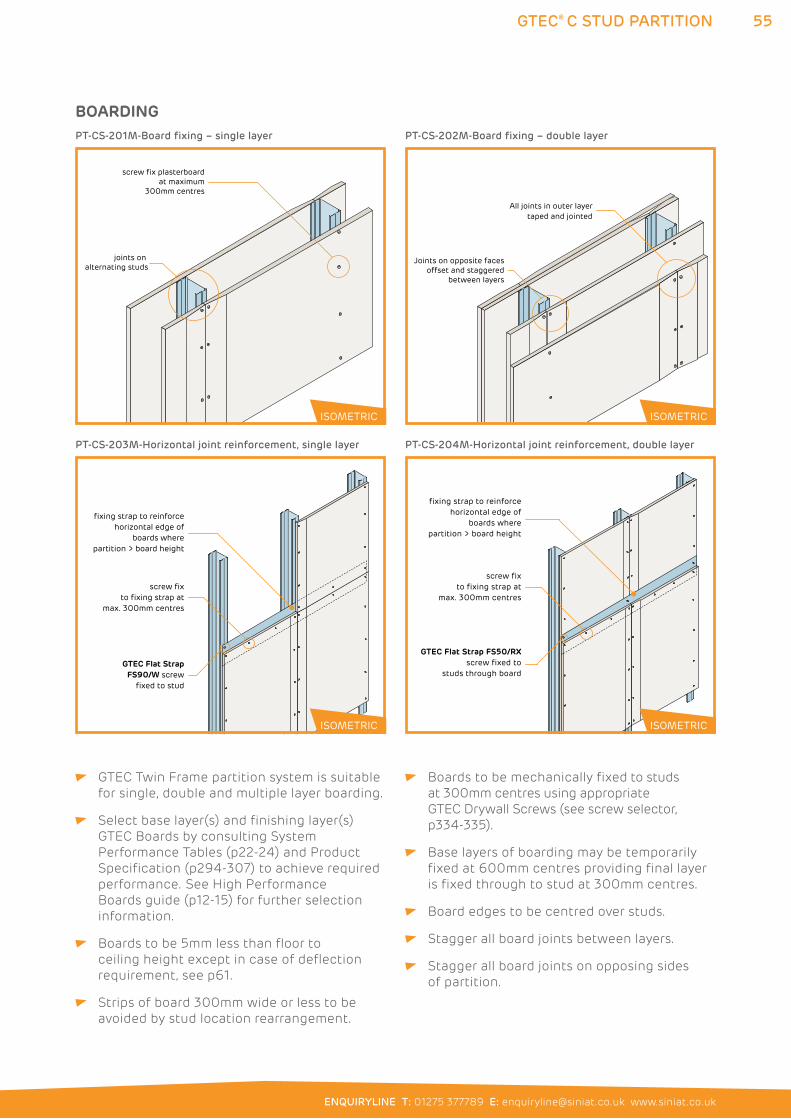
55
ENQUIRYLINE T: 01275 377789 E: [email protected] www.siniat.co.uk
GTEC® C STUD PARTITION
GTEC Twin Frame partition system is suitable
for single, double and multiple layer boarding.
Select base layer(s) and finishing layer(s)
GTEC Boards by consulting System
Performance Tables (p22-24) and Product
Specification (p294-307) to achieve required
performance. See High Performance
Boards guide (p12-15) for further selection
information.
Boards to be 5mm less than floor to
ceiling height except in case of deflection
requirement, see p61.
Strips of board 300mm wide or less to be
avoided by stud location rearrangement.
Boards to be mechanically fixed to studs
at 300mm centres using appropriate
GTEC Drywall Screws (see screw selector,
p334-335).
Base layers of boarding may be temporarily
fixed at 600mm centres providing final layer
is fixed through to stud at 300mm centres.
Board edges to be centred over studs.
Stagger all board joints between layers.
Stagger all board joints on opposing sides
of partition.
joints on alternating studs
screw fix plasterboardat maximum
300mm centres
All joints in outer layertaped and jointed
Joints on opposite faces offset and staggered
between layers
PT-CS-201M-Board fixing – single layer
GTEC Flat Strap FS90/W screw
fixed to stud
fixing strap to reinforce horizontal edge of
boards where partition > board height
screw fix to fixing strap at
max. 300mm centres
PT-CS-203M-Horizontal joint reinforcement, single layer
GTEC Flat Strap FS50/RXscrew fixed to
studs through board
fixing strap to reinforce horizontal edge of
boards where partition > board height
screw fix to fixing strap at
max. 300mm centres
PT-CS-204M-Horizontal joint reinforcement, double layer
PT-CS-202M-Board fixing – double layer
ISOMETRIC
ISOMETRIC
ISOMETRIC
ISOMETRIC
BOARDING
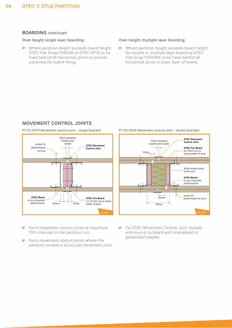
56 GTEC® C STUD PARTITION
Form movement control joints at maximum
10m intervals in the partition run.
Form movement control joints where the
partition crosses a structural movement joint.
Fix GTEC Movement Control Joint, butted
end-to-end, to board with sheradised or
galvanised staples.
10mm between boards and
tracks
10mm 10mm
GTEC Movement Control Joint
screw fix plasterboard
to stud
GTEC Fire Board2 x 15 mm cut to exact width of stud
GTEC Boardto suit required
performance
10mm between boards and tracks
10mm
70mm
20mm screw fix plasterboard to stud
Rock mineral wool to fill void
GTEC Fire Board2x 15mm cut to exact width of stud
GTEC Board to suit required performance
GTEC Movement Control Joint
PT-CS-301P-Movement control joint – single boarded PT-CS-302P-Movement control joint – double boarded
PLANPLAN
Over-height single layer boarding:
Where partition height exceeds board height
GTEC Flat Strap FS90/W or GTEC MFIX to be
fixed behind all horizontal joints to provide
substrate for board fixing.
Over-height multiple layer boarding:
Where partition height exceeds board height
for double or multiple layer boarding GTEC
Flat Strap FS50/RX to be fixed behind all
horizontal joints in outer layer of board.
MOVEMENT CONTROL JOINTS
BOARDING continued
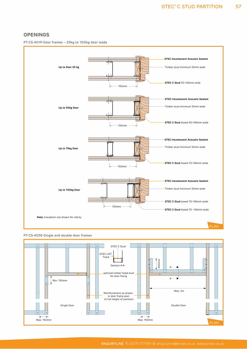
57
ENQUIRYLINE T: 01275 377789 E: [email protected] www.siniat.co.uk
GTEC® C STUD PARTITION
GTEC Intumescent Acoustic Sealant
Timber stud minimum 32mm wide
GTEC C Stud 50-146mm wide
Timber stud minimum 32mm wide
Timber stud minimum 32mm wide
Timber stud minimum 32mm wide
Up to Door 25 kg
Up to 50kg Door
Up to 75kg Door
Up to 100kg Door
150mm
150mm
150mm
150mm
GTEC C Stud boxed 70-146mm wide
GTEC C Stud boxed 70-146mm wide
GTEC C Stud boxed 50-146mm wide
Note: Insulation not shown for clarity
GTEC Intumescent Acoustic Sealant
GTEC Intumescent Acoustic Sealant
GTEC Intumescent Acoustic Sealant
GTEC C Stud boxed 70- 146mm wide
PT-CS-401P-Door frames – 25kg to 100kg door loads
Single Door Double Door
Max. 150mm
Min. 150mm
Section A-A
Reinforcement as shown in door frame plan
to full height of partition
GTEC UXT Track
GTEC C Stud
A
Max. 2m
A40
0m
m
Max. 150mm
optional timber head studfor door fixing
PT-CS-403E-Single and double door frames
PLAN
PLAN
OPENINGS
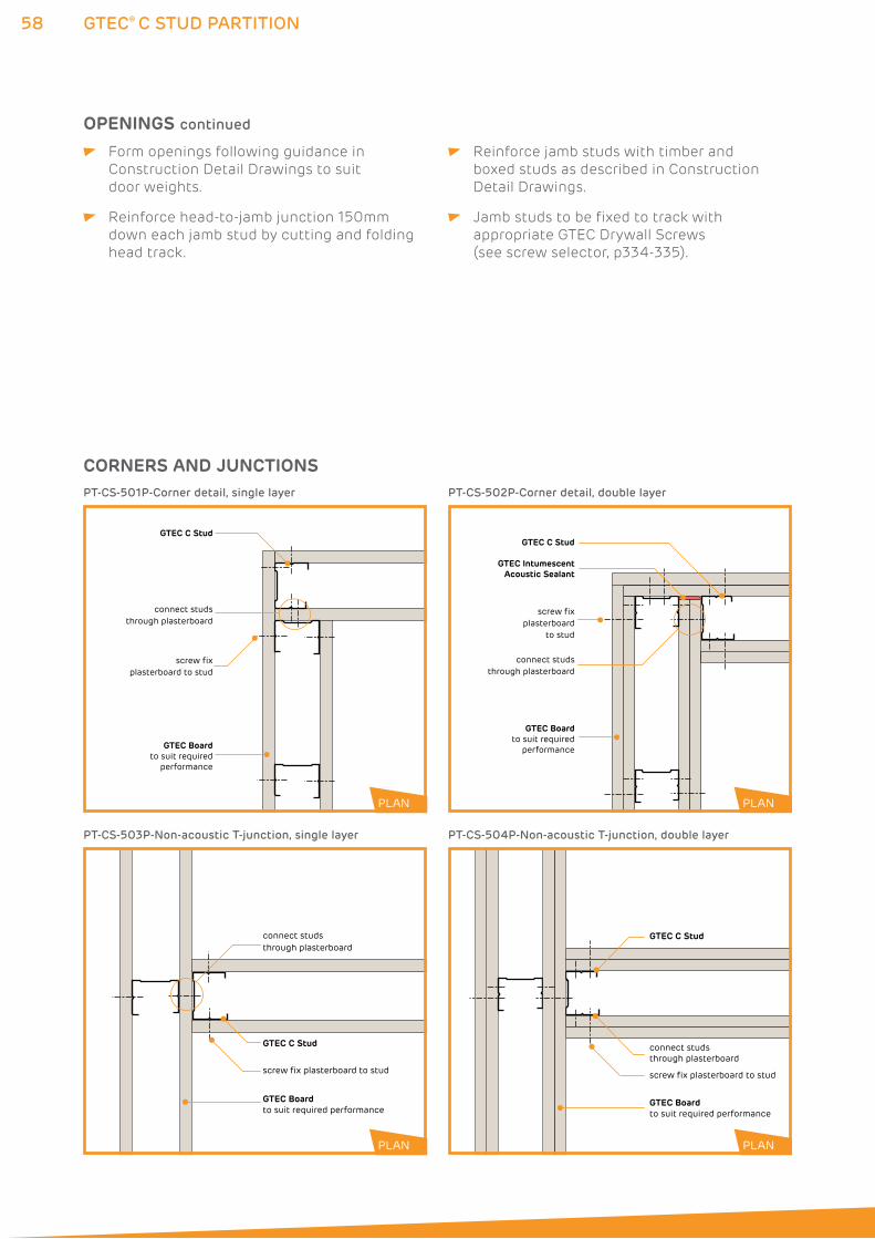
58
CORNERS AND JUNCTIONS
GTEC® C STUD PARTITION
Form openings following guidance in
Construction Detail Drawings to suit
door weights.
Reinforce head-to-jamb junction 150mm
down each jamb stud by cutting and folding
head track.
Reinforce jamb studs with timber and
boxed studs as described in Construction
Detail Drawings.
Jamb studs to be fixed to track with
appropriate GTEC Drywall Screws
(see screw selector, p334-335).
GTEC Boardto suit required
performance
GTEC C Stud
screw fix plasterboard to stud
PLAN
connect studsthrough plasterboard
GTEC C Stud
GTEC Boardto suit required
performance
screw fixplasterboard
to stud
connect studsthrough plasterboard
GTEC IntumescentAcoustic Sealant
PLAN
PT-CS-501P-Corner detail, single layer
screw fix plasterboard to stud
GTEC Boardto suit required performance
GTEC C Stud
PLAN
connect studsthrough plasterboard
PT-CS-503P-Non-acoustic T-junction, single layer
screw fix plasterboard to stud
GTEC Boardto suit required performance
GTEC C Stud
connect studsthrough plasterboard
PT-CS-504P-Non-acoustic T-junction, double layer
PT-CS-502P-Corner detail, double layer
PLAN
PLAN PLAN
PLAN
OPENINGS continued
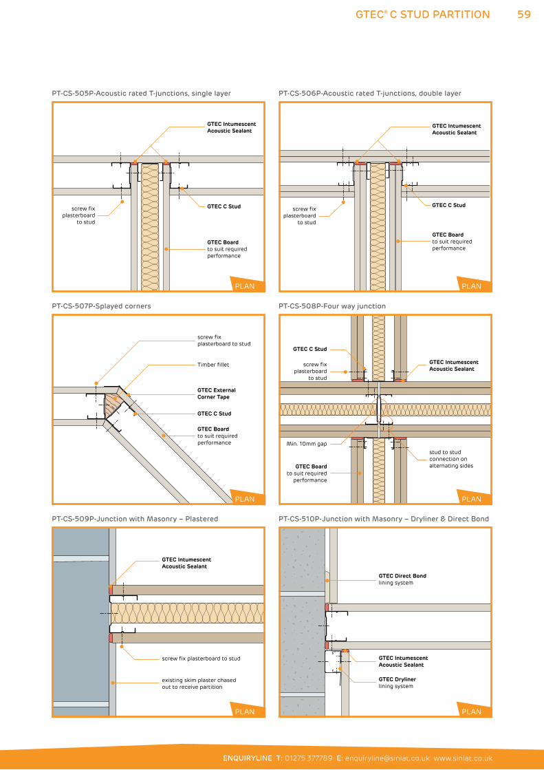
59
ENQUIRYLINE T: 01275 377789 E: [email protected] www.siniat.co.uk
GTEC® C STUD PARTITION
GTEC External Corner Tape
GTEC Boardto suit required performance
Timber fillet
screw fix plasterboard to stud
GTEC C Stud
screw fix plasterboard
to stud
GTEC Boardto suit required
performance
Min. 10mm gapstud to stud connection on alternating sides
GTEC Intumescent Acoustic Sealant
GTEC C Stud
PT-CS-507P-Splayed corners
GTEC Intumescent Acoustic Sealant
screw fix plasterboard to stud
existing skim plaster chased out to receive partition
PT-CS-509P-Junction with Masonry – Plastered
GTEC Intumescent Acoustic Sealant
screw fix plasterboard
to stud
GTEC Boardto suit required performance
GTEC C Stud
PT-CS-505P-Acoustic rated T-junctions, single layer
GTEC Intumescent Acoustic Sealant
GTEC Direct Bondlining system
GTEC Drylinerlining system
PT-CS-510P-Junction with Masonry – Dryliner & Direct Bond
GTEC Intumescent Acoustic Sealant
GTEC Boardto suit required performance
screw fix plasterboard
to stud
GTEC C Stud
PT-CS-506P-Acoustic rated T-junctions, double layer
PT-CS-508P-Four way junction
PLAN
PLAN
PLAN
PLAN
PLAN
PLAN
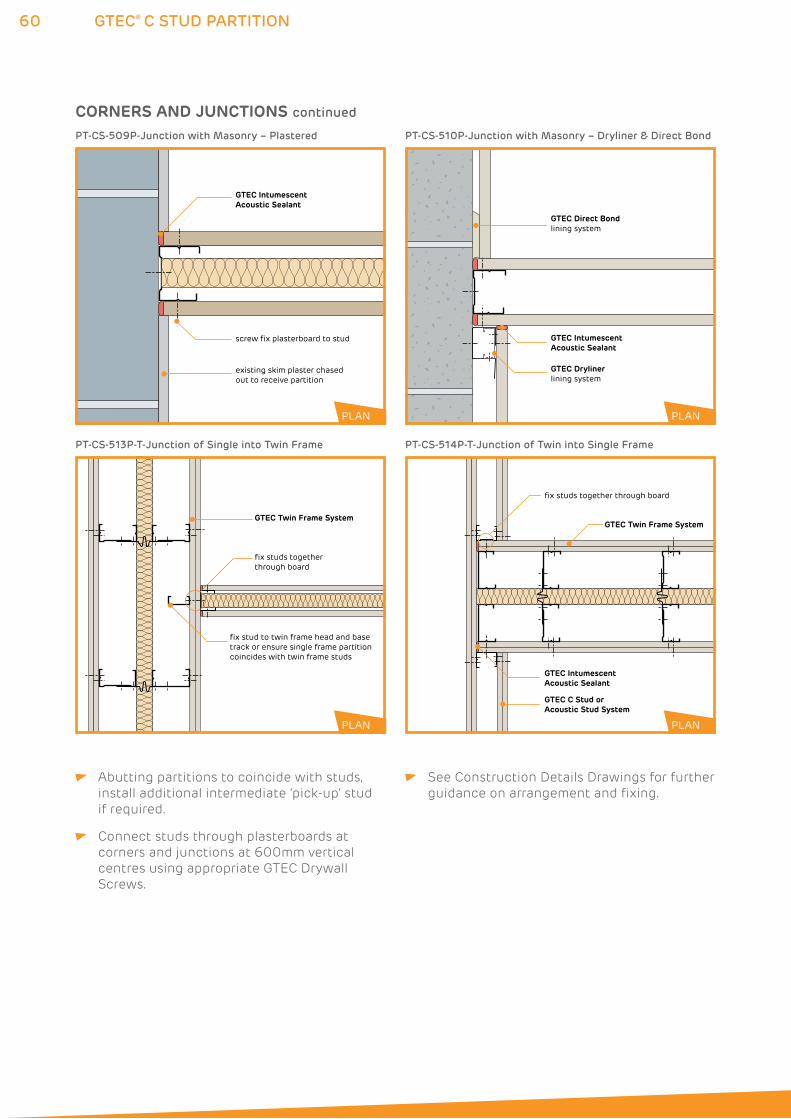
60 GTEC® C STUD PARTITION
GTEC Intumescent Acoustic Sealant
screw fix plasterboard to stud
existing skim plaster chased out to receive partition
PT-CS-509P-Junction with Masonry – Plastered
GTEC Intumescent Acoustic Sealant
GTEC Direct Bondlining system
GTEC Drylinerlining system
PT-CS-510P-Junction with Masonry – Dryliner & Direct Bond
PLAN PLAN
Abutting partitions to coincide with studs,
install additional intermediate ‘pick-up’ stud
if required.
Connect studs through plasterboards at
corners and junctions at 600mm vertical
centres using appropriate GTEC Drywall
Screws.
See Construction Details Drawings for further
guidance on arrangement and fixing.
fix stud to twin frame head and base track or ensure single frame partition coincides with twin frame studs
GTEC Twin Frame System
fix studs togetherthrough board
PT-CS-513P-T-Junction of Single into Twin Frame
GTEC Twin Frame System
GTEC Intumescent Acoustic Sealant
GTEC C Stud or Acoustic Stud System
fix studs together through board
PT-CS-514P-T-Junction of Twin into Single Frame
PLAN PLAN
CORNERS AND JUNCTIONS continued
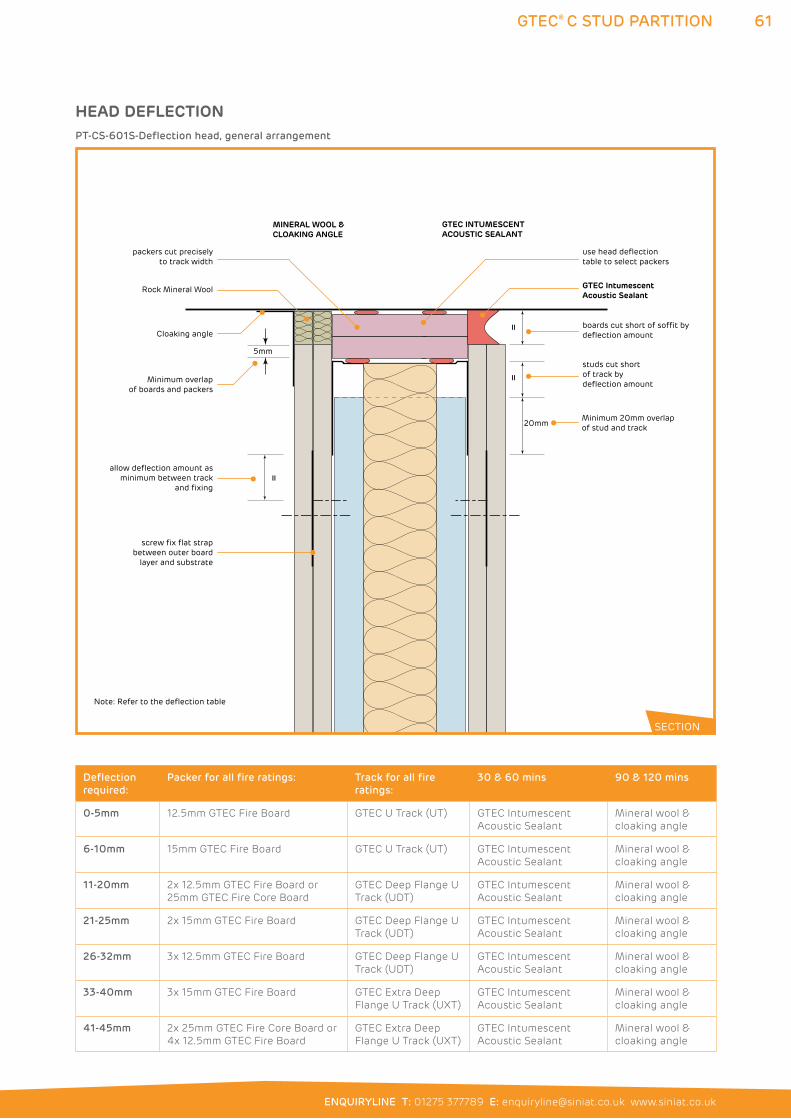
61
ENQUIRYLINE T: 01275 377789 E: [email protected] www.siniat.co.uk
GTEC® C STUD PARTITION
packers cut precisely to track width
use head deflection table to select packers
5mm
Minimum overlap of boards and packers
Rock Mineral Wool
Cloaking angle
20mm Minimum 20mm overlap of stud and track
Note: Refer to the deflection table
MINERAL WOOL &CLOAKING ANGLE
GTEC INTUMESCENTACOUSTIC SEALANT
GTEC IntumescentAcoustic Sealant
screw fix flat strap between outer board
layer and substrate
boards cut short of soffit by deflection amount
allow deflection amount as minimum between track
and fixing
=
==
studs cut short of track by deflection amount
PT-CS-601S-Deflection head, general arrangement
SECTION
HEAD DEFLECTION
Deflection
required:
Packer for all fire ratings: Track for all fire
ratings:
30 & 60 mins 90 & 120 mins
0-5mm 12.5mm GTEC Fire Board GTEC U Track (UT) GTEC Intumescent
Acoustic Sealant
Mineral wool &
cloaking angle
6-10mm 15mm GTEC Fire Board GTEC U Track (UT) GTEC Intumescent
Acoustic Sealant
Mineral wool &
cloaking angle
11-20mm 2x 12.5mm GTEC Fire Board or
25mm GTEC Fire Core Board
GTEC Deep Flange U
Track (UDT)
GTEC Intumescent
Acoustic Sealant
Mineral wool &
cloaking angle
21-25mm 2x 15mm GTEC Fire Board GTEC Deep Flange U
Track (UDT)
GTEC Intumescent
Acoustic Sealant
Mineral wool &
cloaking angle
26-32mm 3x 12.5mm GTEC Fire Board GTEC Deep Flange U
Track (UDT)
GTEC Intumescent
Acoustic Sealant
Mineral wool &
cloaking angle
33-40mm 3x 15mm GTEC Fire Board GTEC Extra Deep
Flange U Track (UXT)
GTEC Intumescent
Acoustic Sealant
Mineral wool &
cloaking angle
41-45mm 2x 25mm GTEC Fire Core Board or
4x 12.5mm GTEC Fire Board
GTEC Extra Deep
Flange U Track (UXT)
GTEC Intumescent
Acoustic Sealant
Mineral wool &
cloaking angle
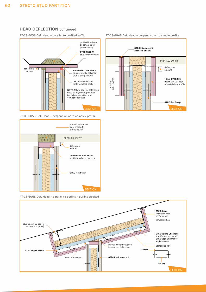
62 GTEC® C STUD PARTITION
profiled insulation by others to fill profile cavity
GTEC FS90Wat 600mm centres
15mm GTEC Fire Boardto close cavity between profile and partition
use head deflection table to select packer
NOTE: follow general deflection head arrangement guidance for full construction and component detail
deflection amount
PT-CS-603S-Def. Head – parallel to profiled soffit
over
lap
Min
. 150
mm
deflection amount
PROFILED SOFFIT
GTEC IntumescentAcoustic Sealant
GTEC Flat Strap
15mm GTEC Fire Board cut to shape of metal deck profile
PT-CS-604S-Def. Head – perpendicular to simple profile
SECTION SECTION
profiled insulation by others to fill profile cavity
15mm GTEC Fire Boardcontinuous head packers
GTEC Flat Strap
PROFILED SOFFIT
deflection amount
PT-CS-605S-Def. Head – perpendicular to complex profile
GTEC Boardto suit required performance
composite box
stud and board cut short by required deflection
deflection amount GTEC Partition to suit
GTEC Edge Channel
stud to pick up top fix(size to suit purlin)
GTEC Ceiling Channels at 400mm centres, with GTEC Edge Channel or angle to edge
Composite box
U Track
C Stud
PT-CS-606S-Def. Head – parallel to purlins – purlins cloaked
SECTION
SECTION
HEAD DEFLECTION continued
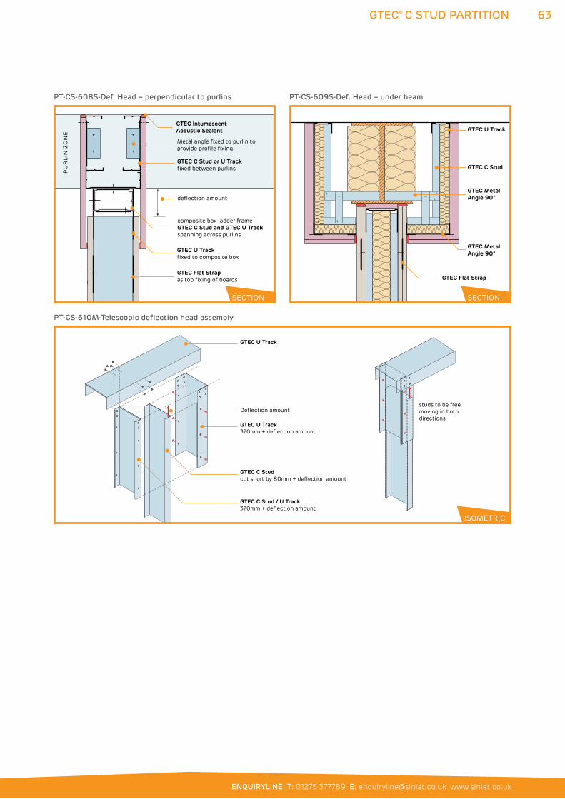
63
ENQUIRYLINE T: 01275 377789 E: [email protected] www.siniat.co.uk
GTEC® C STUD PARTITION
GTEC Intumescent Acoustic Sealant
PU
RLI
N Z
ON
E
Metal angle fixed to purlin to provide profile fixing
GTEC C Stud or U Trackfixed between purlins
composite box ladder frame GTEC C Stud and GTEC U Trackspanning across purlins
GTEC U Track fixed to composite box
GTEC Flat Strapas top fixing of boards
deflection amount
GTEC C Stud
GTEC U Track
GTEC Metal Angle 90°
GTEC Metal Angle 90°
GTEC Flat Strap
PT-CS-609S-Def. Head – under beamPT-CS-608S-Def. Head – perpendicular to purlins
SECTION SECTION
GTEC U Track
GTEC U Track370mm + deflection amount
GTEC C Studcut short by 80mm + deflection amount
studs to be free moving in both directions
Deflection amount
GTEC C Stud / U Track 370mm + deflection amount
PT-CS-610M-Telescopic deflection head assembly
ISOMETRIC
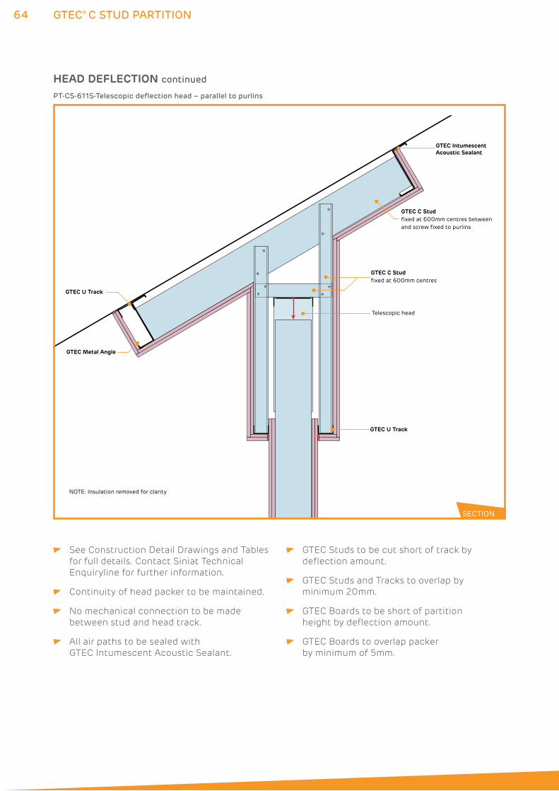
64 GTEC® C STUD PARTITION
GTEC U Track
GTEC C Studfixed at 600mm centres
Telescopic head
GTEC Intumescent Acoustic Sealant
GTEC C Studfixed at 600mm centres between and screw fixed to purlins
GTEC U Track
GTEC Metal Angle
NOTE: Insulation removed for clarity
PT-CS-611S-Telescopic deflection head – parallel to purlins
SECTION
HEAD DEFLECTION continued
See Construction Detail Drawings and Tables
for full details. Contact Siniat Technical
Enquiryline for further information.
Continuity of head packer to be maintained.
No mechanical connection to be made
between stud and head track.
All air paths to be sealed with
GTEC Intumescent Acoustic Sealant.
GTEC Studs to be cut short of track by
deflection amount.
GTEC Studs and Tracks to overlap by
minimum 20mm.
GTEC Boards to be short of partition
height by deflection amount.
GTEC Boards to overlap packer
by minimum of 5mm.
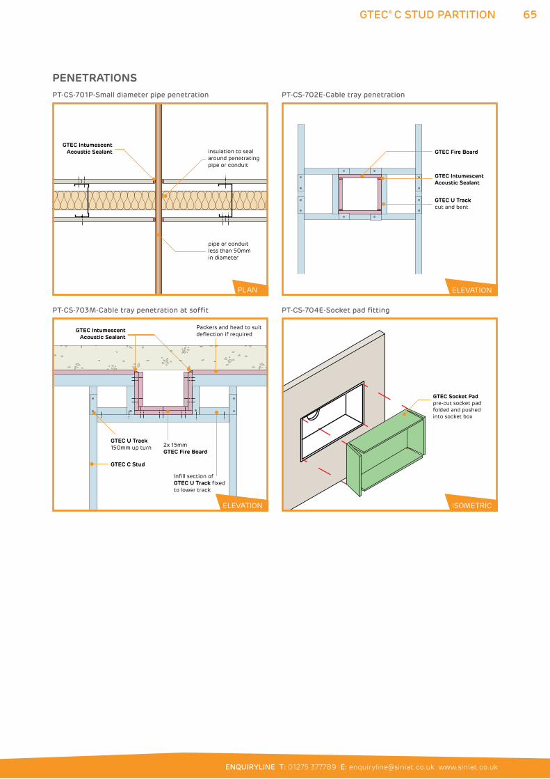
65
ENQUIRYLINE T: 01275 377789 E: [email protected] www.siniat.co.uk
GTEC® C STUD PARTITION
GTEC IntumescentAcoustic Sealant
pipe or conduitless than 50mm in diameter
insulation to seal around penetrating pipe or conduit
PT-CS-701P-Small diameter pipe penetration
GTEC Fire Board
GTEC U Trackcut and bent
GTEC Intumescent Acoustic Sealant
PT-CS-702E-Cable tray penetration
PLAN ELEVATION
PENETRATIONS
GTEC C Stud
GTEC U Track 150mm up turn
Infill section of GTEC U Track fixed to lower track
2x 15mm GTEC Fire Board
Packers and head to suit deflection if required
GTEC IntumescentAcoustic Sealant
PT-CS-703M-Cable tray penetration at soffit
GTEC Socket Padpre-cut socket pad folded and pushedinto socket box
ISOMETRIC
PT-CS-704E-Socket pad fitting
ISOMETRICELEVATION
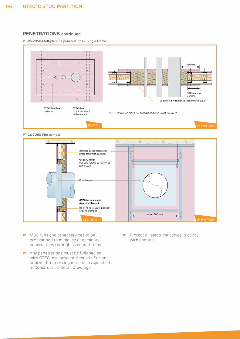
66 GTEC® C STUD PARTITION
GTEC Fire Boardpattress
GTEC Boardto suit required performance
150mm
100mm min.overlap
voisd filled with dense rock mineral wool
NOTE : Insulation may be reduced if partition is not fire-rated
GTEC IntumescentAcoustic Sealant
Rock mineral wool packedaround damper
Fire damper
damper suspension rodsprotected within cavity
max. 600mm
GTEC U Trackcut and folded to reinforcejamb stud
PT-CS-705P-Multiple pipe penetrations – Single frame
PT-CS-706S Fire damper
PLAN ELEVATION
ELEVATION
M&E runs and other services to be
pre-planned to minimise or eliminate
penetrations through rated partitions.
Any penetrations must be fully sealed
with GTEC Intumescent Acoustic Sealant
or other fire resisting material as specified
in Construction Detail Drawings.
Protect all electrical cables in cavity
with conduit.
PENETRATIONS continued
SECTION
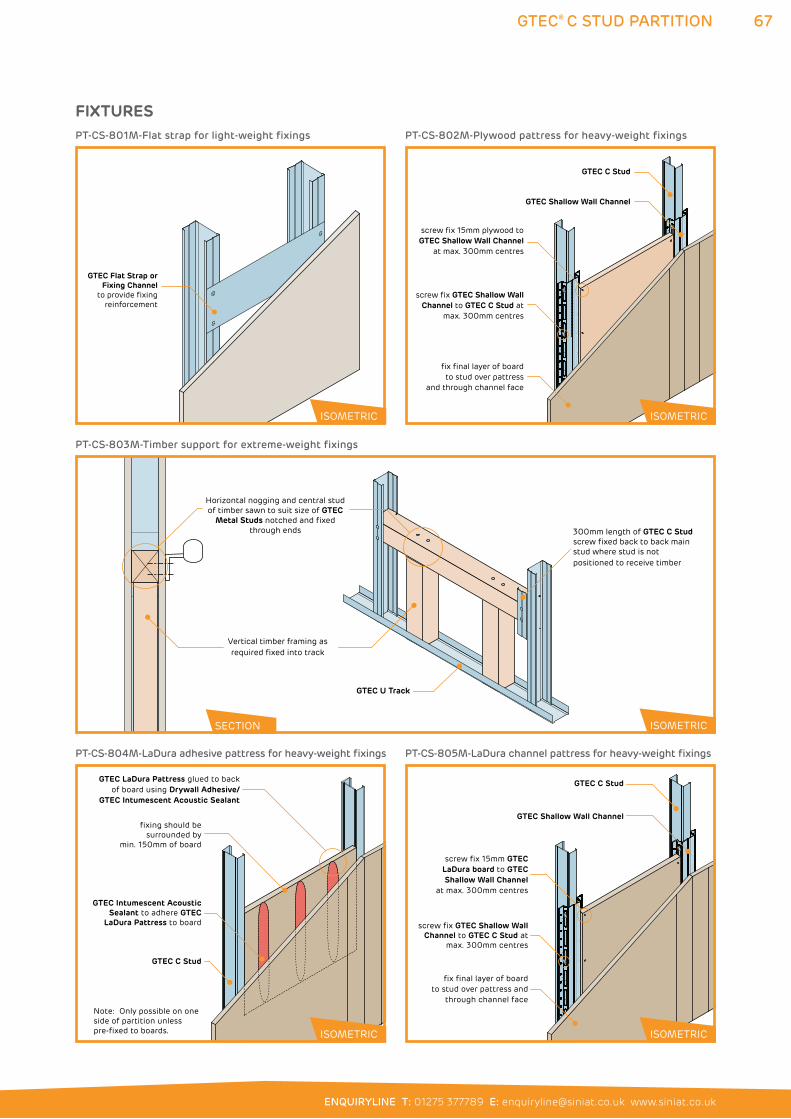
67
ENQUIRYLINE T: 01275 377789 E: [email protected] www.siniat.co.uk
GTEC® C STUD PARTITION
Horizontal nogging and central stud of timber sawn to suit size of GTEC
Metal Studs notched and fixed through ends
GTEC U Track
Vertical timber framing as required fixed into track
300mm length of GTEC C Stud screw fixed back to back main stud where stud is not positioned to receive timber
PT-CS-803M-Timber support for extreme-weight fixings
GTEC Flat Strap or Fixing Channel
to provide fixingreinforcement
ISOMETRIC
PT-CS-801M-Flat strap for light-weight fixings
screw fix GTEC Shallow Wall Channel to GTEC C Stud at
max. 300mm centres
fix final layer of board to stud over pattress
and through channel face
screw fix 15mm plywood to GTEC Shallow Wall Channel
at max. 300mm centres
GTEC Shallow Wall Channel
GTEC C Stud
PT-CS-802M-Plywood pattress for heavy-weight fixings
SECTION
ISOMETRIC ISOMETRIC
ISOMETRIC
FIXTURES
GTEC LaDura Pattress glued to backof board using Drywall Adhesive/
GTEC Intumescent Acoustic Sealant
GTEC C Stud
GTEC Intumescent AcousticSealant to adhere GTEC
LaDura Pattress to board
Note: Only possible on one side of partition unless pre-fixed to boards.
fixing should besurrounded by
min. 150mm of board
PT-CS-804M-LaDura adhesive pattress for heavy-weight fixings
screw fix GTEC Shallow Wall Channel to GTEC C Stud at
max. 300mm centres
fix final layer of board to stud over pattress and
through channel face
screw fix 15mm GTEC LaDura board to GTEC Shallow Wall Channel
at max. 300mm centres
GTEC Shallow Wall Channel
GTEC C Stud
PT-CS-805M-LaDura channel pattress for heavy-weight fixings
ISOMETRIC ISOMETRIC
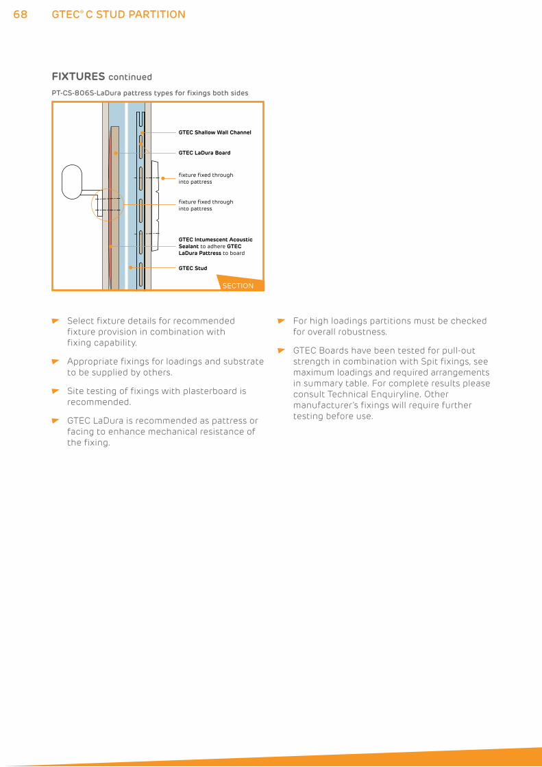
68 GTEC® C STUD PARTITION
GTEC Shallow Wall Channel
fixture fixed throughinto pattress
fixture fixed throughinto pattress
GTEC LaDura Board
GTEC Stud
GTEC Intumescent AcousticSealant to adhere GTECLaDura Pattress to board
PT-CS-806S-LaDura pattress types for fixings both sides
SECTION
Select fixture details for recommended
fixture provision in combination with
fixing capability.
Appropriate fixings for loadings and substrate
to be supplied by others.
Site testing of fixings with plasterboard is
recommended.
GTEC LaDura is recommended as pattress or
facing to enhance mechanical resistance of
the fixing.
For high loadings partitions must be checked
for overall robustness.
GTEC Boards have been tested for pull-out
strength in combination with Spit fixings, see
maximum loadings and required arrangements
in summary table. For complete results please
consult Technical Enquiryline. Other
manufacturer’s fixings will require further
testing before use.
FIXTURES continued
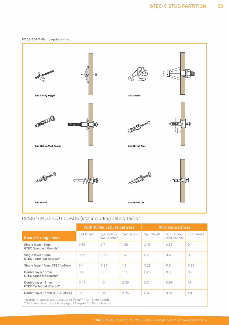
69
ENQUIRYLINE T: 01275 377789 E: [email protected] www.siniat.co.uk
GTEC® C STUD PARTITION
Spit Driva® Plus
Spit Driva® LDSpit Driva®
Spit Satelis
Spit Hollow Wall Anchor
Spit Spring Toggle
PT-CS-807M-Fixing options chart
With 15mm LaDura pattress Without pattress
Board ArrangementSpit Driva® Spit Hollow
Wall Anchor
Spit Satelis Spit Driva® Spit Hollow
Wall Anchor
Spit Satelis
Single layer 15mm
GTEC Standard Boards*
0.35 0.7 1.25 0.15 0.35 0.4
Single layer 15mm
GTEC Technical Boards**
0.35 0.75 1.4 0.2 0.4 0.5
Single layer 15mm GTEC LaDura 0.4 0.85 1.8 0.25 0.5 0.85
Double layer 15mm
GTEC Standard Boards*
0.4 0.85 1.55 0.25 0.55 0.7
Double layer 15mm
GTEC Technical Boards**
0.45 1.0 2.05 0.3 0.65 1.1
Double layer 15mm GTEC LaDura 0.5 1.15 2.85 0.4 0.85 1.8
*Standard boards are those up to 10kg/m2 for 15mm boards
**Technical boards are those up to 13kg/m2 for 15mm boards
DESIGN PULL-OUT LOADS (kN) including safety factor
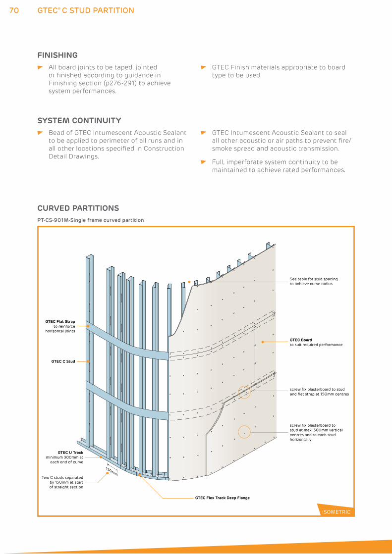
70 GTEC® C STUD PARTITION
FINISHING All board joints to be taped, jointed
or finished according to guidance in
Finishing section (p276-291) to achieve
system performances.
GTEC Finish materials appropriate to board
type to be used.
SYSTEM CONTINUITY Bead of GTEC Intumescent Acoustic Sealant
to be applied to perimeter of all runs and in
all other locations specified in Construction
Detail Drawings.
GTEC Intumescent Acoustic Sealant to seal
all other acoustic or air paths to prevent fire/
smoke spread and acoustic transmission.
Full, imperforate system continuity to be
maintained to achieve rated performances.
GTEC C Stud
GTEC Flex Track Deep Flange
GTEC Boardto suit required performance
screw fix plasterboard to studand flat strap at 150mm centres
GTEC Flat Strapto reinforce
horizontal joints
Two C studs separated by 150mm at start of straight section
See table for stud spacing to achieve curve radius
150mm
screw fix plasterboard tostud at max. 300mm vertical centres and to each stud horizontally
GTEC U Trackminimum 300mm at
each end of curve
PT-CS-901M-Single frame curved partition
ISOMETRIC
CURVED PARTITIONS
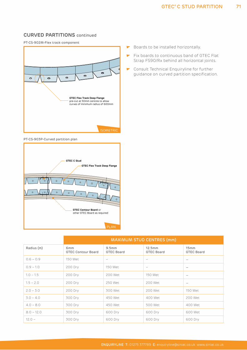
71
ENQUIRYLINE T: 01275 377789 E: [email protected] www.siniat.co.uk
GTEC® C STUD PARTITION
Boards to be installed horizontally.
Fix boards to continuous band of GTEC Flat
Strap FS90/Rx behind all horizontal joints.
Consult Technical Enquiryline for further
guidance on curved partition specification.
GTEC Flex Track Deep Flange
GTEC C Stud
GTEC Contour Board orother GTEC Board as required
PT-CS-903P-Curved partition plan
GTEC Flex Track Deep Flangepre-cut at 50mm centres to allow curves of minimum radius of 600mm
PT-CS-902M-Flex track component
ISOMETRIC
PLAN
CURVED PARTITIONS continued
MAXIMUM STUD CENTRES (mm)
Radius (m) 6mm
GTEC Contour Board
9.5mm
GTEC Board
12.5mm
GTEC Board
15mm
GTEC Board
0.6 – 0.9 150 Wet – – –
0.9 – 1.0 200 Dry 150 Wet – –
1.0 – 1.5 200 Dry 200 Wet 150 Wet –
1.5 – 2.0 200 Dry 250 Wet 200 Wet –
2.0 – 3.0 200 Dry 300 Wet 200 Wet 150 Wet
3.0 – 4.0 300 Dry 450 Wet 400 Wet 200 Wet
4.0 – 8.0 300 Dry 450 Wet 500 Wet 400 Wet
8.0 – 12.0 300 Dry 600 Dry 600 Dry 600 Wet
12.0 – 300 Dry 600 Dry 600 Dry 600 Dry
72 GTEC® ACOUSTIC STUD PARTITION
GTEC® ACOUSTIC STUD PARTITION SYSTEMSThe GTEC Acoustic Stud is an alternative to 70mm, 90mm and
146mm GTEC C Studs, where higher levels of acoustic performance
are needed from a partition.
With a unique profile design, the engineered slots create a spring
section, resulting in less acoustic energy being transmitted through
the stud and sound is absorbed within the partition.
Compatibility with the GTEC C Stud system and all GTEC Boards
allows a range of partition performances within identical footprints.
For individual system performances, refer to the System Performance
Tables on pages 22 to 44.
WHERE TO USE: GTEC Acoustic Stud is an internal partition system for commercial and
domestic applications requiring high acoustic performance levels.
FEATURES BENEFITS
Compatible with GTEC U Tracks Only requires one change in component in a
specification and on site
Partition types can be mixed on site
Unique spring section design Can eliminate insulation or board layers to
achieve acoustic performance
Benefits from all key features as detailed for GTEC C Stud, plus:
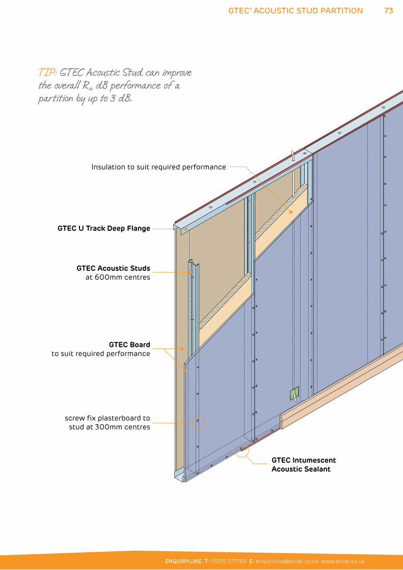
73
ENQUIRYLINE T: 01275 377789 E: [email protected] www.siniat.co.uk
GTEC® ACOUSTIC STUD PARTITION
GTEC Acoustic Studsat 600mm centres
GTEC Intumescent Acoustic Sealant
GTEC Boardto suit required performance
screw fix plasterboard to stud at 300mm centres
Insulation to suit required performance
GTEC U Track Deep Flange
TIP: GTEC Acoustic Stud can improve the overall Rw dB performance of a partition by up to 3 dB.
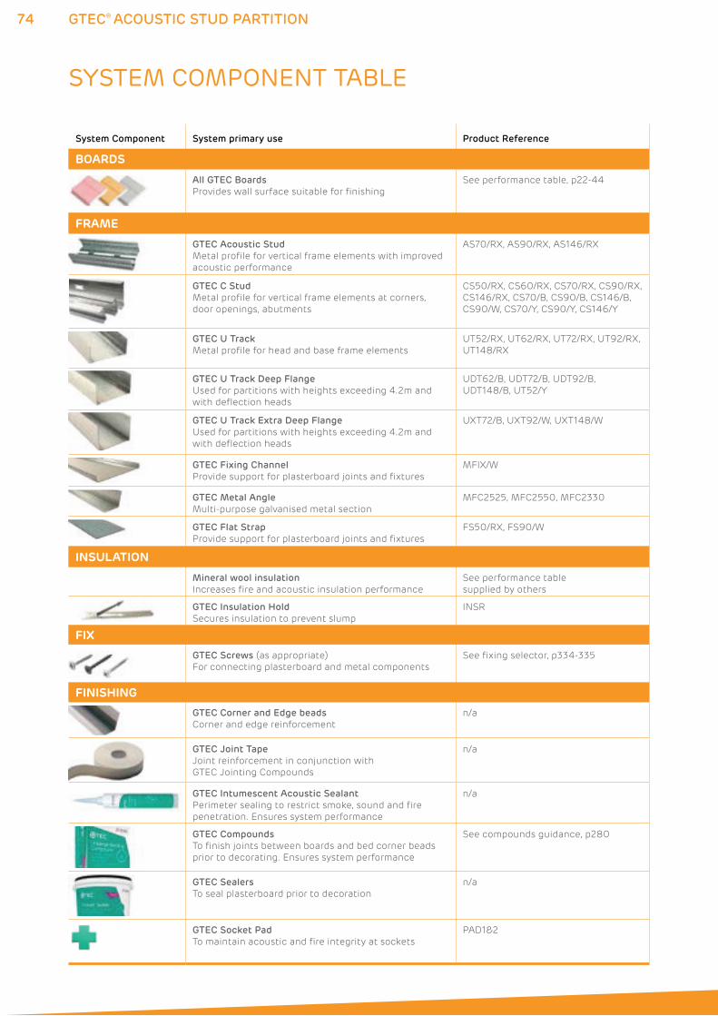
74 GTEC® ACOUSTIC STUD PARTITION
SYSTEM COMPONENT TABLE
System Component System primary use Product Reference
BOARDS
All GTEC Boards
Provides wall surface suitable for finishing
See performance table, p22-44
FRAME
GTEC Acoustic Stud
Metal profile for vertical frame elements with improved
acoustic performance
AS70/RX, AS90/RX, AS146/RX
GTEC C Stud
Metal profile for vertical frame elements at corners,
door openings, abutments
CS50/RX, CS60/RX, CS70/RX, CS90/RX,
CS146/RX, CS70/B, CS90/B, CS146/B,
CS90/W, CS70/Y, CS90/Y, CS146/Y
GTEC U Track
Metal profile for head and base frame elements
UT52/RX, UT62/RX, UT72/RX, UT92/RX,
UT148/RX
GTEC U Track Deep Flange
Used for partitions with heights exceeding 4.2m and
with deflection heads
UDT62/B, UDT72/B, UDT92/B,
UDT148/B, UT52/Y
GTEC U Track Extra Deep Flange
Used for partitions with heights exceeding 4.2m and
with deflection heads
UXT72/B, UXT92/W, UXT148/W
GTEC Fixing Channel
Provide support for plasterboard joints and fixtures
MFIX/W
GTEC Metal Angle
Multi-purpose galvanised metal section
MFC2525, MFC2550, MFC2330
GTEC Flat Strap
Provide support for plasterboard joints and fixtures
FS50/RX, FS90/W
INSULATION
Mineral wool insulation
Increases fire and acoustic insulation performance
See performance table
supplied by others
GTEC Insulation Hold
Secures insulation to prevent slump
INSR
FIX
GTEC Screws (as appropriate)
For connecting plasterboard and metal components
See fixing selector, p334-335
FINISHING
GTEC Corner and Edge beads
Corner and edge reinforcement
n/a
GTEC Joint Tape
Joint reinforcement in conjunction with
GTEC Jointing Compounds
n/a
GTEC Intumescent Acoustic Sealant
Perimeter sealing to restrict smoke, sound and fire
penetration. Ensures system performance
n/a
GTEC Compounds
To finish joints between boards and bed corner beads
prior to decorating. Ensures system performance
See compounds guidance, p280
GTEC Sealers
To seal plasterboard prior to decoration
n/a
GTEC Socket Pad
To maintain acoustic and fire integrity at sockets
PAD1&2
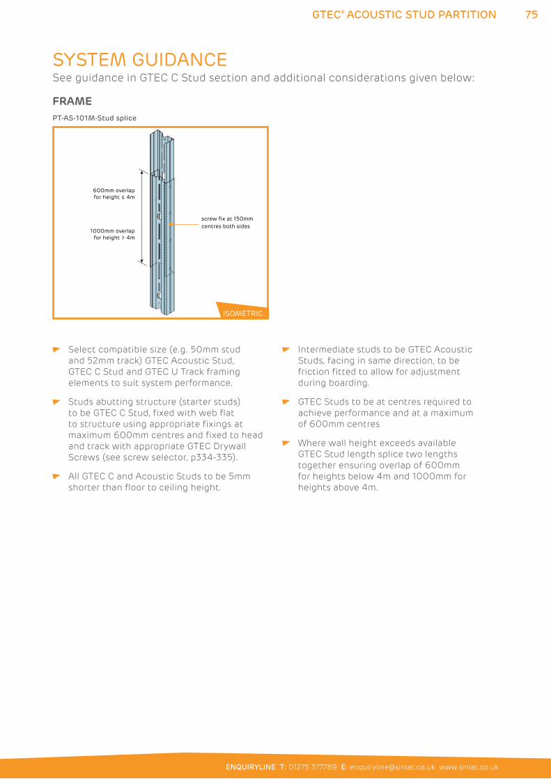
75
ENQUIRYLINE T: 01275 377789 E: [email protected] www.siniat.co.uk
GTEC® ACOUSTIC STUD PARTITION
Select compatible size (e.g. 50mm stud
and 52mm track) GTEC Acoustic Stud,
GTEC C Stud and GTEC U Track framing
elements to suit system performance.
Studs abutting structure (starter studs)
to be GTEC C Stud, fixed with web flat
to structure using appropriate fixings at
maximum 600mm centres and fixed to head
and track with appropriate GTEC Drywall
Screws (see screw selector, p334-335).
All GTEC C and Acoustic Studs to be 5mm
shorter than floor to ceiling height.
Intermediate studs to be GTEC Acoustic
Studs, facing in same direction, to be
friction fitted to allow for adjustment
during boarding.
GTEC Studs to be at centres required to
achieve performance and at a maximum
of 600mm centres
Where wall height exceeds available
GTEC Stud length splice two lengths
together ensuring overlap of 600mm
for heights below 4m and 1000mm for
heights above 4m.
screw fix at 150mm centres both sides
600mm overlapfor height ≤ 4m
1000mm overlapfor height > 4m
PT-AS-101M-Stud splice
ISOMETRIC
SYSTEM GUIDANCE
FRAME
See guidance in GTEC C Stud section and additional considerations given below:
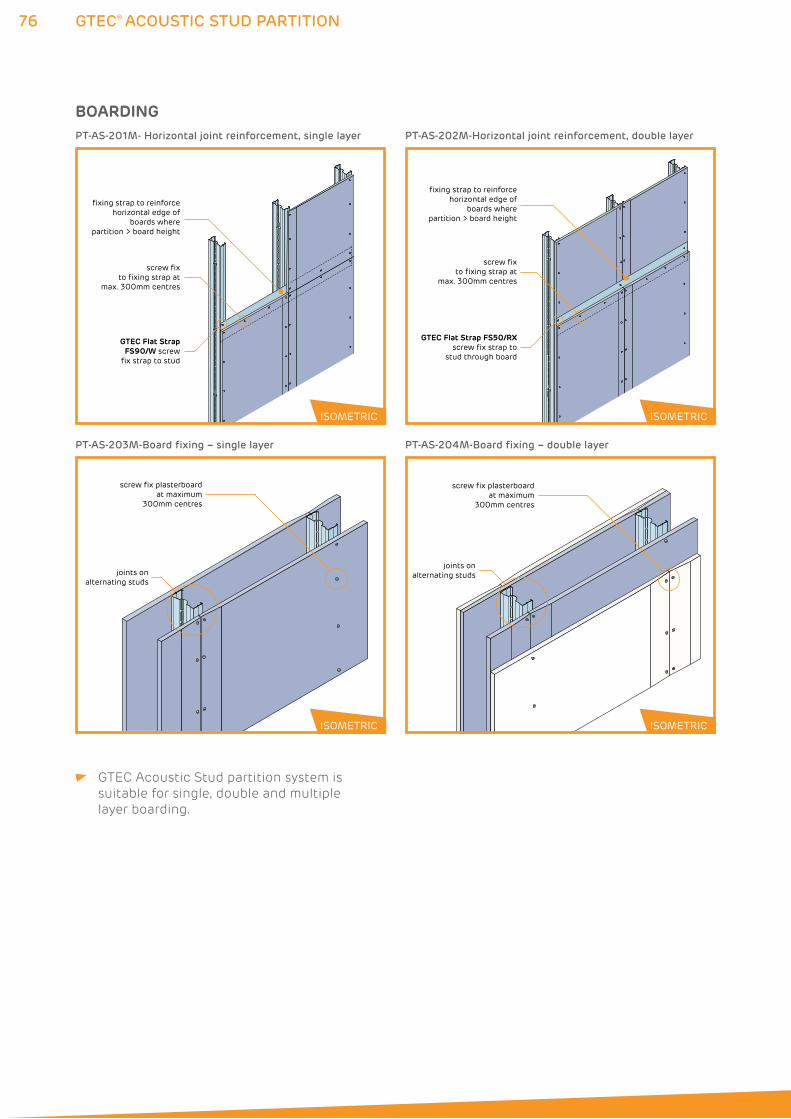
76 GTEC® ACOUSTIC STUD PARTITION
GTEC Acoustic Stud partition system is
suitable for single, double and multiple
layer boarding.
BOARDING
joints onalternating studs
screw fix plasterboard at maximum
300mm centres
joints onalternating studs
screw fix plasterboardat maximum
300mm centres
PT-AS-203M-Board fixing – single layer
GTEC Flat Strap FS90/W screw
fix strap to stud
fixing strap to reinforce horizontal edge of
boards where partition > board height
screw fix to fixing strap at
max. 300mm centres
PT-AS-201M- Horizontal joint reinforcement, single layer
GTEC Flat Strap FS50/RXscrew fix strap to
stud through board
fixing strap to reinforce horizontal edge of
boards where partition > board height
screw fix to fixing strap at
max. 300mm centres
PT-AS-202M-Horizontal joint reinforcement, double layer
PT-AS-204M-Board fixing – double layer
ISOMETRIC ISOMETRIC
ISOMETRIC ISOMETRIC
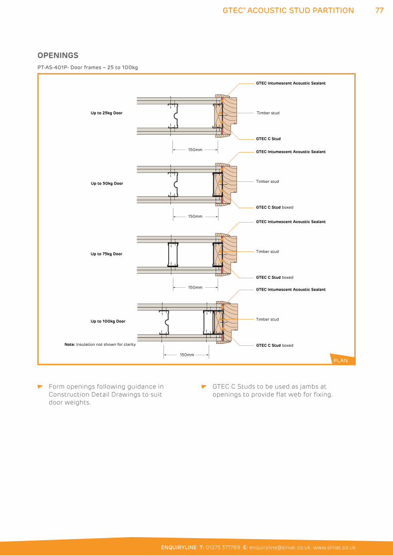
77
ENQUIRYLINE T: 01275 377789 E: [email protected] www.siniat.co.uk
GTEC® ACOUSTIC STUD PARTITION
Form openings following guidance in
Construction Detail Drawings to suit
door weights.
GTEC C Studs to be used as jambs at
openings to provide flat web for fixing.
OPENINGS
150mm
150mm
150mm
150mm
GTEC Intumescent Acoustic Sealant
Timber stud
GTEC C Stud
GTEC Intumescent Acoustic Sealant
Timber stud
GTEC C Stud boxed
GTEC Intumescent Acoustic Sealant
Timber stud
GTEC C Stud boxed
GTEC Intumescent Acoustic Sealant
Timber stud
Note: Insulation not shown for clarity GTEC C Stud boxed
Up to 25kg Door
Up to 50kg Door
Up to 75kg Door
Up to 100kg Door
PT-AS-401P- Door frames – 25 to 100kg
PLAN
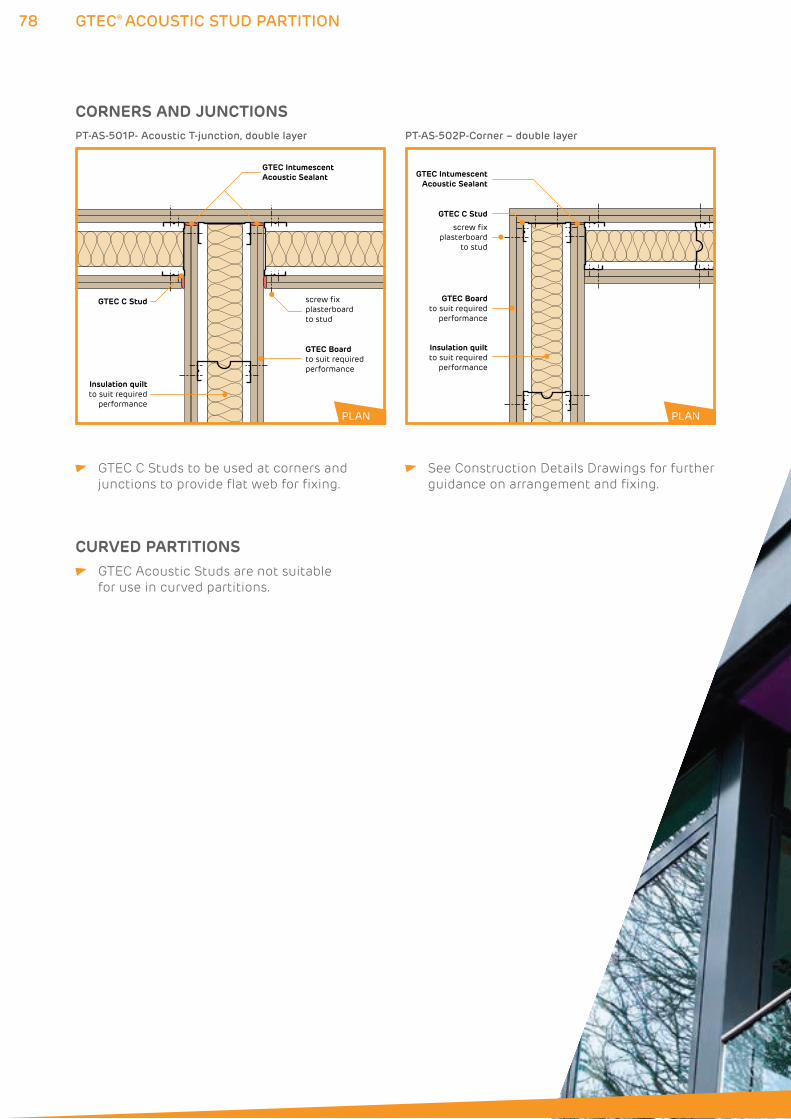
78
screw fix plasterboard to stud
GTEC Intumescent Acoustic Sealant
GTEC Boardto suit required performance
Insulation quiltto suit required
performance
GTEC C Stud
PT-AS-501P- Acoustic T-junction, double layer
GTEC IntumescentAcoustic Sealant
GTEC Boardto suit required
performance
screw fix plasterboard
to stud
Insulation quiltto suit required
performance
GTEC C Stud
PT-AS-502P-Corner – double layer
GTEC® ACOUSTIC STUD PARTITION
GTEC C Studs to be used at corners and
junctions to provide flat web for fixing.
See Construction Details Drawings for further
guidance on arrangement and fixing.
CURVED PARTITIONS GTEC Acoustic Studs are not suitable
for use in curved partitions.
CORNERS AND JUNCTIONS
PLAN PLAN
80 GTEC® ACOUSTIC HOMESPAN PARTITION
GTEC® ACOUSTIC HOMESPAN PARTITION SYSTEMSThe GTEC Acoustic Homespan system is a lightweight
partition specifically designed to meet Building Regulation
Part E where 40RwdB is required for internal partitions
in dwellings. This performance is achieved using 44mm
and 50mm GTEC Acoustic Homespan Studs and Tracks
and GTEC Acoustic Homespan Board without the need to
install insulation to achieve a 40RwdB rating.
The narrow stud width and specially configured boards
simplify specification and use the least material to achieve
the demands of Part E.
WHERE TO USE: GTEC Acoustic Homespan is an internal partition for
new-build domestic applications.
FEATURES BENEFITS
Achieves acoustic performance using narrow
width studs
Maintains a low system footprint to minimise
the effect on the room size
Achieves acoustic performance without the
need for insulation
Quicker to install than other systems which use
insulation to achieve the same performance
Benefits from all key features as detailed for GTEC C Stud, plus:
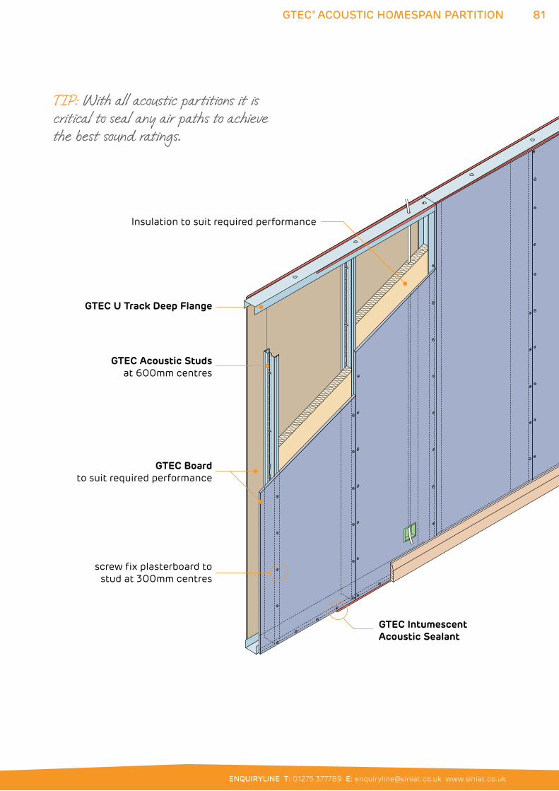
81
ENQUIRYLINE T: 01275 377789 E: [email protected] www.siniat.co.uk
GTEC® ACOUSTIC HOMESPAN PARTITION
GTEC Acoustic Studsat 600mm centres
GTEC Intumescent Acoustic Sealant
GTEC Boardto suit required performance
screw fix plasterboard to stud at 300mm centres
Insulation to suit required performance
GTEC U Track Deep Flange
TIP: With all acoustic partitions it is critical to seal any air paths to achieve the best sound ratings.
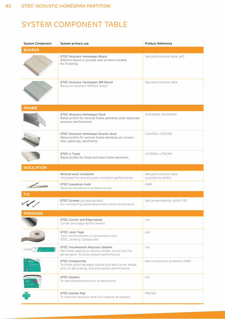
82 GTEC® ACOUSTIC HOMESPAN PARTITION
SYSTEM COMPONENT TABLE
System Component System primary use Product Reference
BOARDS
GTEC Acoustic Homespan Board
900mm board to provide wall surface suitable for finishing
See performance table, p43
GTEC Acoustic Homespan MR Board
Moisture resistant 900mm board
See performance table
FRAME
GTEC Acoustic Homespan Stud
Metal profile for vertical frame elements with improved acoustic performance
AHS44/RX, AHS50/RX
GTEC Acoustic Homespan Starter Stud
Metal profile for vertical frame elements at corners, door openings, abutments
CS44/RX, CS50/RX
GTEC U Track
Metal profile for head and base frame elements
UT45/RX, UT52/RX
INSULATION
Mineral wool insulation
Increases fire and acoustic insulation performance
See performance table
supplied by others
GTEC Insulation Hold
Secures insulation to prevent slump
INSR
FIX
GTEC Screws (as appropriate)
For connecting plasterboard and metal components
See screw selector, p334-335
FINISHING
GTEC Corner and Edge beads
Corner and edge reinforcement
n/a
GTEC Joint Tape
Joint reinforcement in conjunction with
GTEC Jointing Compounds
n/a
GTEC Intumescent Acoustic Sealant
Perimeter sealing to restrict smoke, sound and fire
penetration. Ensures system performance
n/a
GTEC Compounds
To finish joints between boards and bed corner beads
prior to decorating. Ensures system performance
See compounds guidance, p280
GTEC Sealers
To seal plasterboard prior to decoration
n/a
GTEC Socket Pad
To maintain acoustic and fire integrity at sockets
PAD1&2
83
ENQUIRYLINE T: 01275 377789 E: [email protected] www.siniat.co.uk
GTEC® ACOUSTIC HOMESPAN PARTITION
FRAME Select compatible size (e.g. 44mm stud
and 45mm track) GTEC Acoustic Homespan
Stud, GTEC Acoustic Homespan Starter Stud
and GTEC U Track framing elements to suit
system performance.
GTEC Acoustic Homespan is not suitable for
heights above 2.8m and so does not require
deeper flange tracks.
Studs abutting structure to be GTEC Acoustic
Homespan Starter Studs fixed with web flat
to structure using appropriate fixings at
maximum 600mm centres and fixed to head
and track with appropriate GTEC Drywall
Screws (see screw selector, p334-335).
Intermediate GTEC Acoustic Homespan
Studs, facing in same direction, to be
friction fitted to allow for adjustment
during boarding.
All GTEC Studs to be 5mm shorter than
floor to ceiling height.
GTEC Acoustic Homespan Studs to be
at a maximum of 450mm centres.
INSULATION Insulation is not required to achieve
40 RwdB performance with the GTEC
Acoustic Homespan system but may
be fitted to increase performance,
see performance tables p43.
SYSTEM GUIDANCESee guidance in GTEC C Stud section and additional considerations given below:
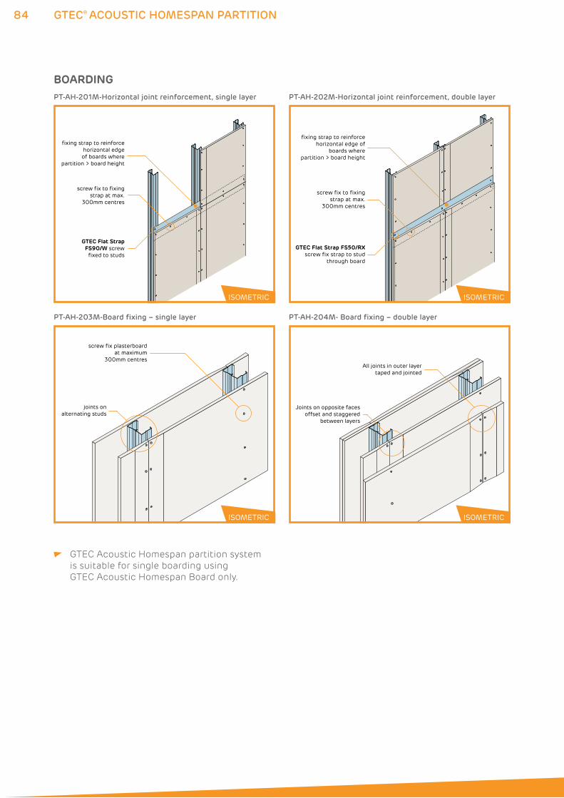
84 GTEC® ACOUSTIC HOMESPAN PARTITION
GTEC Acoustic Homespan partition system
is suitable for single boarding using
GTEC Acoustic Homespan Board only.
joints onalternating studs
screw fix plasterboardat maximum
300mm centresAll joints in outer layer
taped and jointed
Joints on opposite faces offset and staggered
between layers
PT-AH-203M-Board fixing – single layer PT-AH-204M- Board fixing – double layer
ISOMETRIC ISOMETRIC
BOARDING
GTEC Flat Strap FS90/W screw
fixed to studs
fixing strap to reinforce horizontal edge of boards where
partition > board height
screw fix to fixing strap at max.
300mm centres
PT-AH-201M-Horizontal joint reinforcement, single layer
fixing strap to reinforce horizontal edge of
boards where partition > board height
GTEC Flat Strap FS50/RXscrew fix strap to stud
through board
screw fix to fixing strap at max.
300mm centres
PT-AH-202M-Horizontal joint reinforcement, double layer
ISOMETRIC ISOMETRIC
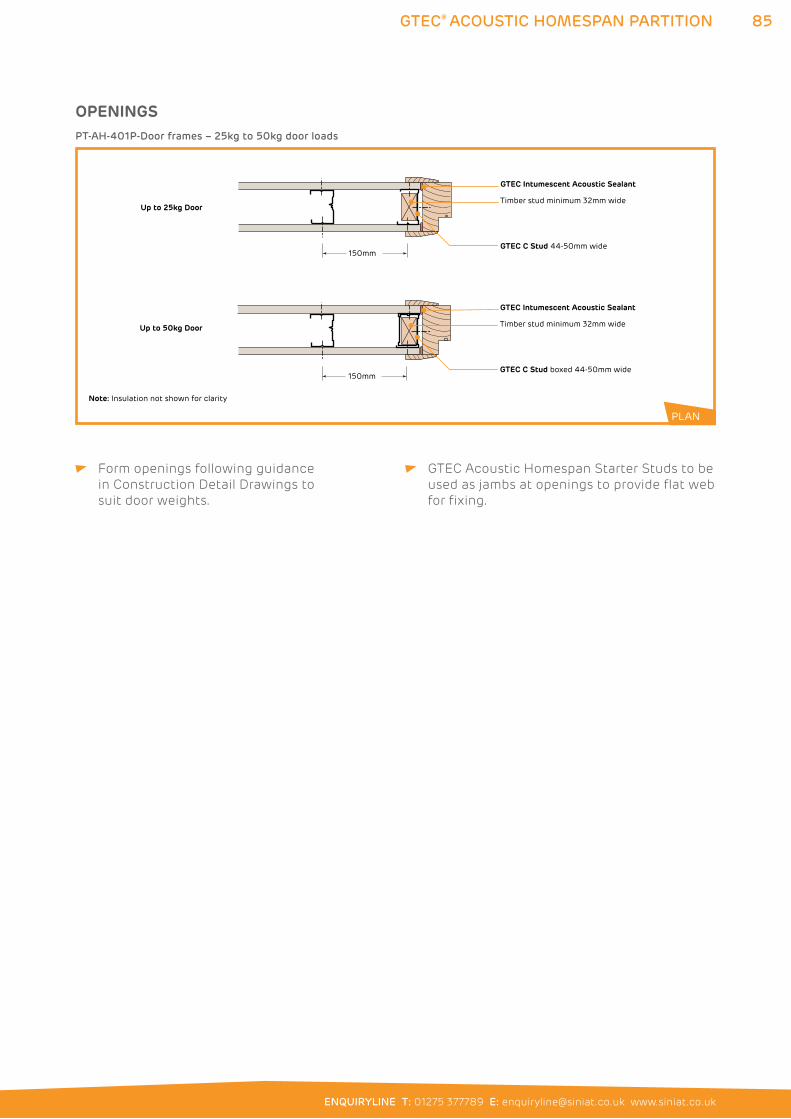
85
ENQUIRYLINE T: 01275 377789 E: [email protected] www.siniat.co.uk
GTEC® ACOUSTIC HOMESPAN PARTITION
Form openings following guidance
in Construction Detail Drawings to
suit door weights.
GTEC Acoustic Homespan Starter Studs to be
used as jambs at openings to provide flat web
for fixing.
OPENINGS
Timber stud minimum 32mm wide
Up to 25kg Door
Up to 50kg Door
150mmGTEC C Stud boxed 44-50mm wide
Note: Insulation not shown for clarity
GTEC Intumescent Acoustic Sealant
Timber stud minimum 32mm wide
150mmGTEC C Stud 44-50mm wide
GTEC Intumescent Acoustic Sealant
PT-AH-401P-Door frames – 25kg to 50kg door loads
PLAN
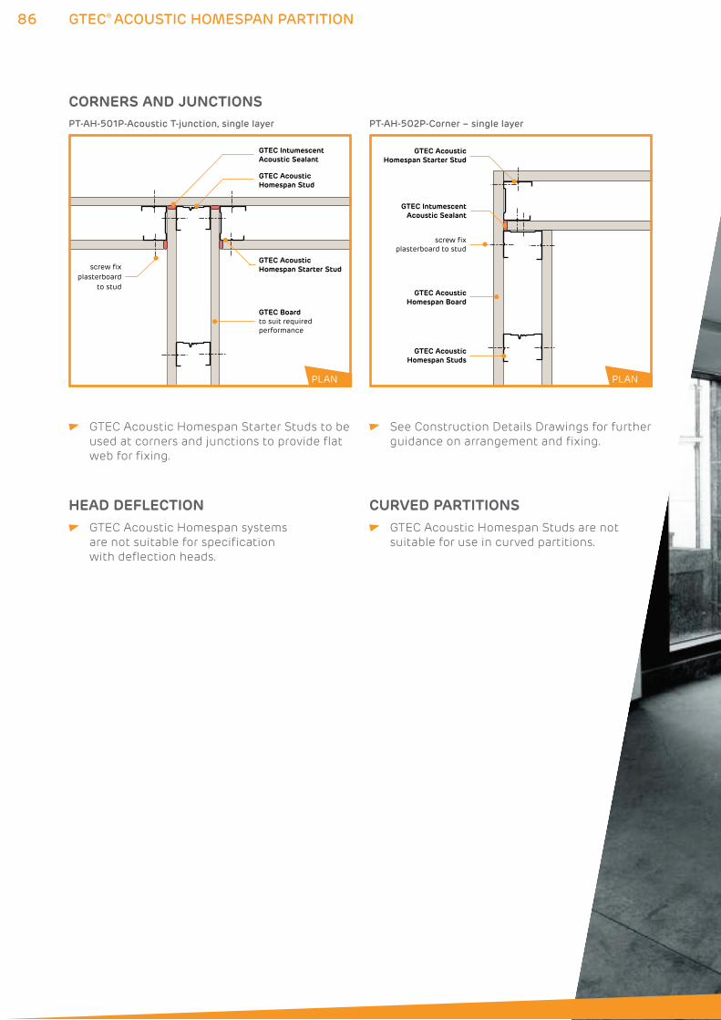
86 GTEC® ACOUSTIC HOMESPAN PARTITION
CORNERS AND JUNCTIONS
GTEC Intumescent Acoustic Sealant
screw fix plasterboard
to stud
GTEC Boardto suit required performance
GTEC Acoustic Homespan Starter Stud
GTEC Acoustic Homespan Stud
PT-AH-501P-Acoustic T-junction, single layer
GTEC IntumescentAcoustic Sealant
GTEC AcousticHomespan Board
GTEC AcousticHomespan Studs
screw fix plasterboard to stud
GTEC AcousticHomespan Starter Stud
PT-AH-502P-Corner – single layer
PLAN PLAN
GTEC Acoustic Homespan Starter Studs to be
used at corners and junctions to provide flat
web for fixing.
See Construction Details Drawings for further
guidance on arrangement and fixing.
HEAD DEFLECTION GTEC Acoustic Homespan systems
are not suitable for specification
with deflection heads.
CURVED PARTITIONS GTEC Acoustic Homespan Studs are not
suitable for use in curved partitions.
88 GTEC® RESILIENT BAR PARTITION
GTEC® RESILIENT BAR PARTITION SYSTEMSGTEC Resilient Bar is a versatile component that can be used with
a variety of partitions to provide improved acoustic performance.
GTEC Resilient Bar decouples the plasterboard from the metal frame
to reduce sound transmission with little increase in thickness. It is
fixed across the flanges of GTEC C Stud and GTEC Board to provide a
substrate for the plasterboard away from the metal framing. Refer to
the System Performance Tables on pages 22 to 44 for full details.
See the GTEC Timber Partitions section for details on using the
GTEC Resilient Bar with timber construction.
WHERE TO USE: GTEC Resilient Bar is used with the GTEC C Stud Partition system
in both domestic and commercial applications.
FEATURES BENEFITS
Easy to fit and install Reduced installation time compared with more
complex systems
Low profile component design Increases acoustics with minimal effect
on room size
Decouples board and frame Gives increase in acoustic performance
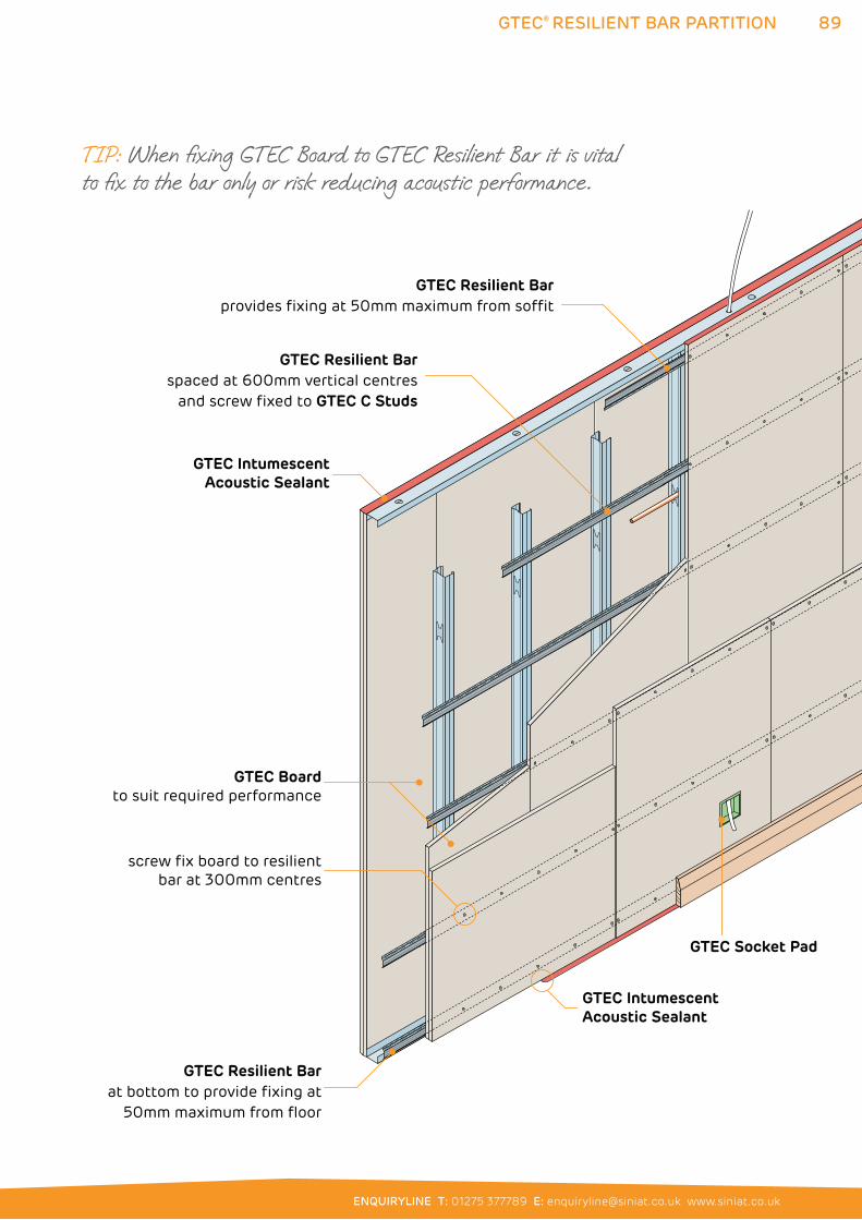
89
ENQUIRYLINE T: 01275 377789 E: [email protected] www.siniat.co.uk
GTEC® RESILIENT BAR PARTITION
GTEC Intumescent Acoustic Sealant
GTEC Socket Pad
GTEC Boardto suit required performance
screw fix board to resilientbar at 300mm centres
GTEC Resilient Barat bottom to provide fixing at
50mm maximum from floor
GTEC Resilient Barprovides fixing at 50mm maximum from soffit
GTEC Resilient Barspaced at 600mm vertical centres
and screw fixed to GTEC C Studs
GTEC IntumescentAcoustic Sealant
TIP: When fixing GTEC Board to GTEC Resilient Bar it is vital to fix to the bar only or risk reducing acoustic performance.
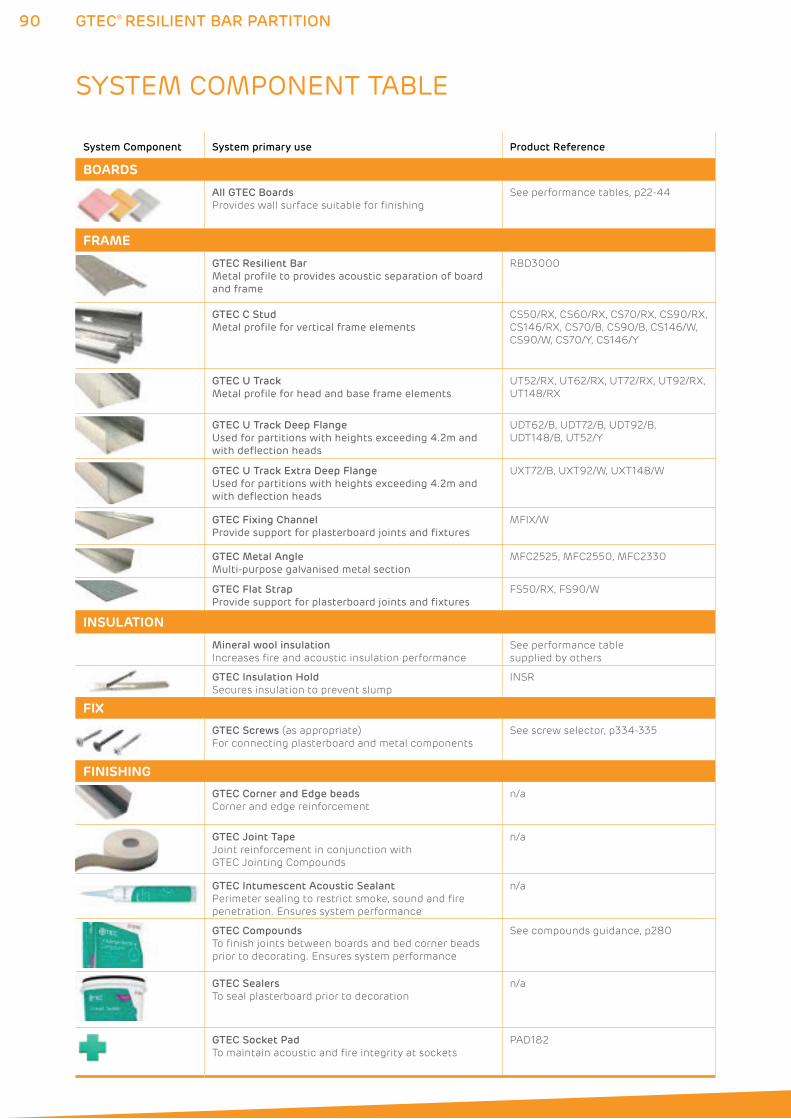
90 GTEC® RESILIENT BAR PARTITION
SYSTEM COMPONENT TABLE
System Component System primary use Product Reference
BOARDS
All GTEC Boards
Provides wall surface suitable for finishing
See performance tables, p22-44
FRAME
GTEC Resilient Bar
Metal profile to provides acoustic separation of board and frame
RBD3000
GTEC C Stud
Metal profile for vertical frame elementsCS50/RX, CS60/RX, CS70/RX, CS90/RX,
CS146/RX, CS70/B, CS90/B, CS146/W,
CS90/W, CS70/Y, CS146/Y
GTEC U Track
Metal profile for head and base frame elementsUT52/RX, UT62/RX, UT72/RX, UT92/RX,
UT148/RX
GTEC U Track Deep Flange
Used for partitions with heights exceeding 4.2m and with deflection heads
UDT62/B, UDT72/B, UDT92/B,
UDT148/B, UT52/Y
GTEC U Track Extra Deep Flange
Used for partitions with heights exceeding 4.2m and with deflection heads
UXT72/B, UXT92/W, UXT148/W
GTEC Fixing Channel
Provide support for plasterboard joints and fixturesMFIX/W
GTEC Metal Angle
Multi-purpose galvanised metal sectionMFC2525, MFC2550, MFC2330
GTEC Flat Strap
Provide support for plasterboard joints and fixturesFS50/RX, FS90/W
INSULATION
Mineral wool insulation
Increases fire and acoustic insulation performance
See performance table
supplied by others
GTEC Insulation Hold
Secures insulation to prevent slump
INSR
FIX
GTEC Screws (as appropriate)
For connecting plasterboard and metal components
See screw selector, p334-335
FINISHING
GTEC Corner and Edge beads
Corner and edge reinforcement
n/a
GTEC Joint Tape
Joint reinforcement in conjunction with
GTEC Jointing Compounds
n/a
GTEC Intumescent Acoustic Sealant
Perimeter sealing to restrict smoke, sound and fire
penetration. Ensures system performance
n/a
GTEC Compounds
To finish joints between boards and bed corner beads
prior to decorating. Ensures system performance
See compounds guidance, p280
GTEC Sealers
To seal plasterboard prior to decoration
n/a
GTEC Socket Pad
To maintain acoustic and fire integrity at sockets
PAD1&2
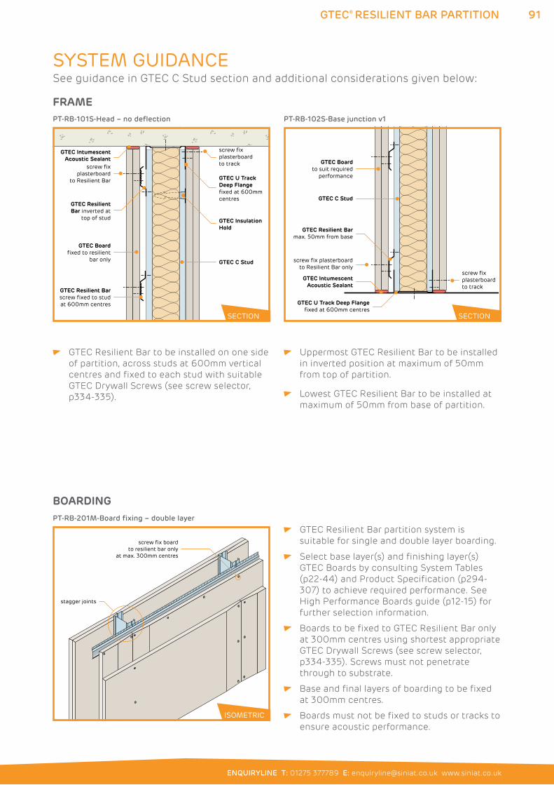
91
ENQUIRYLINE T: 01275 377789 E: [email protected] www.siniat.co.uk
GTEC® RESILIENT BAR PARTITION
GTEC Resilient Bar to be installed on one side
of partition, across studs at 600mm vertical
centres and fixed to each stud with suitable
GTEC Drywall Screws (see screw selector,
p334-335).
Uppermost GTEC Resilient Bar to be installed
in inverted position at maximum of 50mm
from top of partition.
Lowest GTEC Resilient Bar to be installed at
maximum of 50mm from base of partition.
GTEC Resilient Bar partition system is
suitable for single and double layer boarding.
Select base layer(s) and finishing layer(s)
GTEC Boards by consulting System Tables
(p22-44) and Product Specification (p294-
307) to achieve required performance. See
High Performance Boards guide (p12-15) for
further selection information.
Boards to be fixed to GTEC Resilient Bar only
at 300mm centres using shortest appropriate
GTEC Drywall Screws (see screw selector,
p334-335). Screws must not penetrate
through to substrate.
Base and final layers of boarding to be fixed
at 300mm centres.
Boards must not be fixed to studs or tracks to
ensure acoustic performance.
SYSTEM GUIDANCE
FRAME
GTEC U Track Deep Flangefixed at 600mmcentres
GTEC IntumescentAcoustic Sealant
GTEC InsulationHold
GTEC C Stud
screw fix plasterboard to trackscrew fix
plasterboard to Resilient Bar
GTEC ResilientBar inverted at
top of stud
GTEC Boardfixed to resilient
bar only
GTEC Resilient Barscrew fixed to studat 600mm centres
PT-RB-101S-Head – no deflection
GTEC IntumescentAcoustic Sealant
GTEC C Stud
screw fix plasterboard to track
GTEC Boardto suit required
performance
screw fix plasterboard to Resilient Bar only
GTEC U Track Deep Flangefixed at 600mm centres
GTEC Resilient Barmax. 50mm from base
PT-RB-102S-Base junction v1
BOARDING
ISOMETRIC
screw fix boardto resilient bar only
at max. 300mm centres
stagger joints
PT-RB-201M-Board fixing – double layer
ISOMETRIC
SECTION SECTION
See guidance in GTEC C Stud section and additional considerations given below:
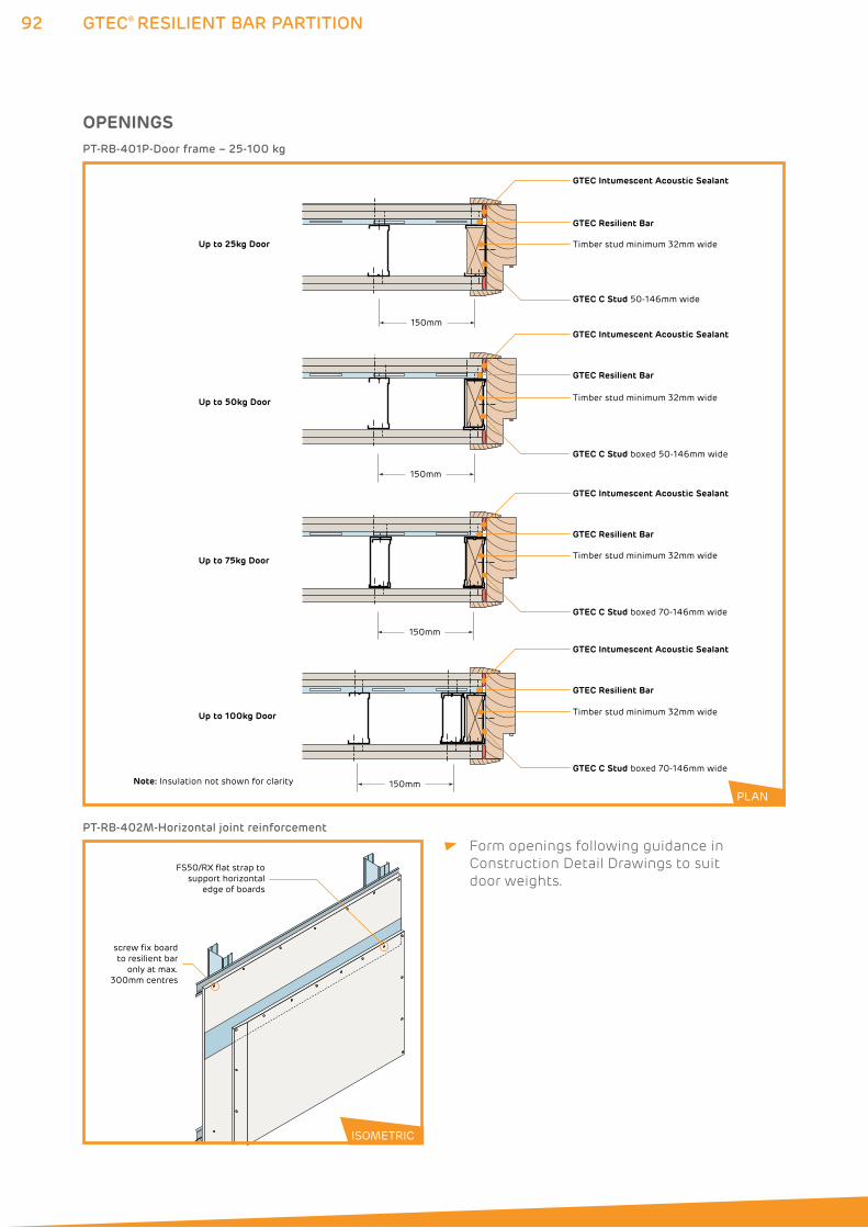
92 GTEC® RESILIENT BAR PARTITION
Form openings following guidance in
Construction Detail Drawings to suit
door weights.
OPENINGS
GTEC Intumescent Acoustic Sealant
GTEC Intumescent Acoustic Sealant
GTEC Resilient Bar
GTEC Resilient Bar
Timber stud minimum 32mm wide
GTEC C Stud 50-146mm wide
GTEC Intumescent Acoustic Sealant
GTEC Resilient Bar
GTEC Intumescent Acoustic Sealant
GTEC Resilient Bar
Timber stud minimum 32mm wide
Timber stud minimum 32mm wide
Timber stud minimum 32mm wide
Up to 25kg Door
Up to 50kg Door
Up to 75kg Door
Up to 100kg Door
150mm
150mm
150mm
150mm
GTEC C Stud boxed 70-146mm wide
GTEC C Stud boxed 70-146mm wide
GTEC C Stud boxed 50-146mm wide
Note: Insulation not shown for clarity
screw fix boardto resilient bar
only at max. 300mm centres
FS50/RX flat strap to support horizontal
edge of boards
PT-RB-401P-Door frame – 25-100 kg
PT-RB-402M-Horizontal joint reinforcement
ISOMETRIC
PLAN
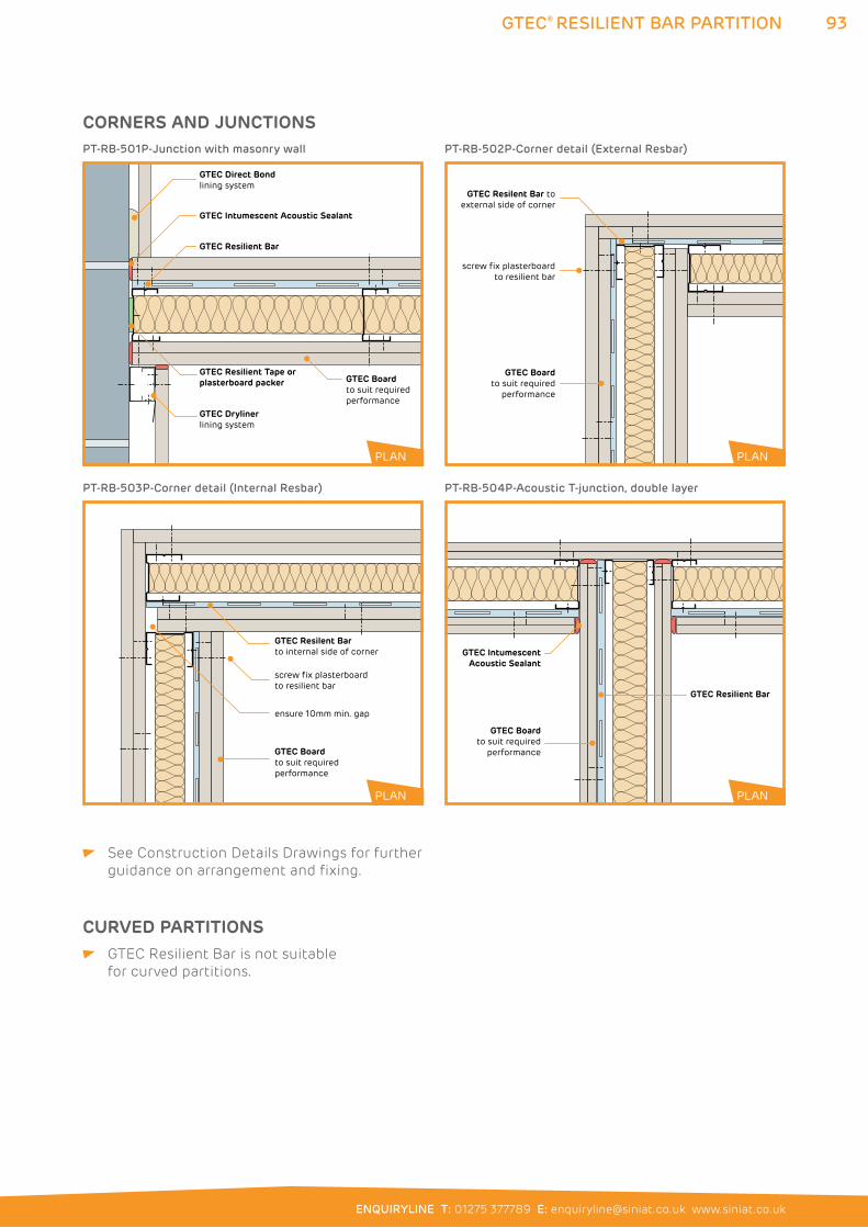
93
ENQUIRYLINE T: 01275 377789 E: [email protected] www.siniat.co.uk
GTEC® RESILIENT BAR PARTITION
CORNERS AND JUNCTIONS
GTEC Resilient Tape orplasterboard packer GTEC Board
to suit required performance
GTEC Intumescent Acoustic Sealant
GTEC Resilient Bar
GTEC Direct Bondlining system
GTEC Drylinerlining system
PT-RB-501P-Junction with masonry wall
GTEC Boardto suit required performance
screw fix plasterboard to resilient bar
ensure 10mm min. gap
GTEC Resilent Barto internal side of corner
PT-RB-503P-Corner detail (Internal Resbar)
GTEC Boardto suit required
performance
screw fix plasterboard to resilient bar
GTEC Resilent Bar toexternal side of corner
PT-RB-502P-Corner detail (External Resbar)
GTEC IntumescentAcoustic Sealant
GTEC Resilient Bar
PLAN
GTEC Boardto suit required
performance
PT-RB-504P-Acoustic T-junction, double layer
PLAN
PLAN
PLAN
PLAN
See Construction Details Drawings for further
guidance on arrangement and fixing.
CURVED PARTITIONS GTEC Resilient Bar is not suitable
for curved partitions.
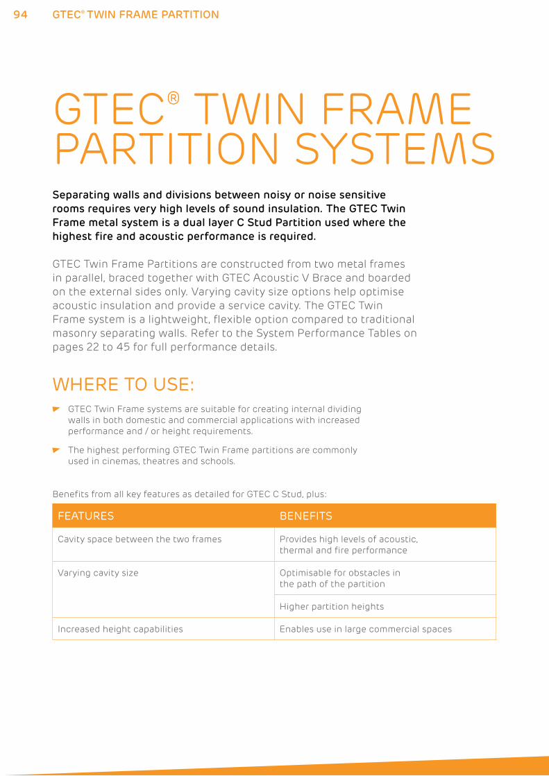
94 GTEC® TWIN FRAME PARTITION
GTEC® TWIN FRAME PARTITION SYSTEMSSeparating walls and divisions between noisy or noise sensitive
rooms requires very high levels of sound insulation. The GTEC Twin
Frame metal system is a dual layer C Stud Partition used where the
highest fire and acoustic performance is required.
GTEC Twin Frame Partitions are constructed from two metal frames
in parallel, braced together with GTEC Acoustic V Brace and boarded
on the external sides only. Varying cavity size options help optimise
acoustic insulation and provide a service cavity. The GTEC Twin
Frame system is a lightweight, flexible option compared to traditional
masonry separating walls. Refer to the System Performance Tables on
pages 22 to 45 for full performance details.
WHERE TO USE: GTEC Twin Frame systems are suitable for creating internal dividing
walls in both domestic and commercial applications with increased
performance and / or height requirements.
The highest performing GTEC Twin Frame partitions are commonly
used in cinemas, theatres and schools.
FEATURES BENEFITS
Cavity space between the two frames Provides high levels of acoustic,
thermal and fire performance
Varying cavity size Optimisable for obstacles in
the path of the partition
Higher partition heights
Increased height capabilities Enables use in large commercial spaces
Benefits from all key features as detailed for GTEC C Stud, plus:
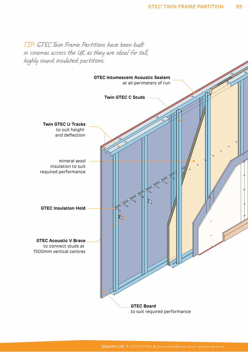
95
ENQUIRYLINE T: 01275 377789 E: [email protected] www.siniat.co.uk
GTEC® TWIN FRAME PARTITION
Twin GTEC U Tracksto suit height and deflection
GTEC Intumescent Acoustic Sealantat all perimeters of run
Twin GTEC C Studs
GTEC Acoustic V Braceto connect studs at
1500mm vertical centres
GTEC Boardto suit required performance
GTEC Insulation Hold
mineral woolinsulation to suit
required performance
TIP: GTEC Twin Frame Partitions have been built in cinemas across the UK as they are ideal for tall, highly sound insulated partitions.

96 GTEC® TWIN FRAME PARTITION
SYSTEM COMPONENT TABLE
System Component System primary use Product Reference
BOARDS
All GTEC Boards
Provides wall surface suitable for finishing
See performance table, p22-45
FRAME
GTEC C Stud
Metal profile for vertical frame elementsCS50/RX, CS60/RX, CS70/RX, CS90/RX,
CS146/RX, CS70/B, CS90/B, CS146/B,
CS90/W, CS70/Y, CS90/Y, CS146/Y
GTEC I Stud
Alternative metal profile for vertical frame elementsIS50/RX, IS60/B, IS60/B, IS70/B, IS90/B
GTEC U Track
Metal profile for head and base frame elementsUT52/RX, UT62/RX, UT72/RX, UT92/RX,
UT148/RX
GTEC U Track Deep Flange
Used for partitions with heights exceeding 4.2m and with deflection heads
UDT62/B, UDT72/B, UDT92/B,
UDT148/B, UT52/Y
GTEC U Track Extra Deep Flange
Used for partitions with heights exceeding 4.2m and with deflection heads
UXT72/B, UXT92/W, UXT148/W
GTEC Acoustic V Brace
Acoustic frame bracing
VBRACE
GTEC Acoustic V Brace 90
Acoustic frame bracing for connecting at 90°
VBRACE90
GTEC Resilient Tape
Provides acoustic isolation between components
RAFT50
GTEC Fixing Channel
Provide support for plasterboard joints and fixturesMFIX/W
GTEC Metal Angle
Multi-purpose galvanised metal sectionMFC2525, MFC2550, MFC2330
GTEC Flat Strap
Provide support for plasterboard joints and fixturesFS50/RX, FS90/W
GTEC Flex Track Deep Flange
Steel track for curved partitions
DFLEX/B
INSULATION
Mineral wool insulation
Increases fire and acoustic insulation performance
See performance table
supplied by others
GTEC Insulation Hold
Secures insulation to prevent slump
INSR
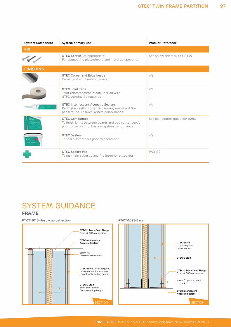
97
ENQUIRYLINE T: 01275 377789 E: [email protected] www.siniat.co.uk
GTEC® TWIN FRAME PARTITION
System Component System primary use Product Reference
FIX
GTEC Screws (as appropriate)
For connecting plasterboard and metal components
See screw selector, p334-335
FINISHING
GTEC Corner and Edge beads
Corner and edge reinforcement
n/a
GTEC Joint Tape
Joint reinforcement in conjunction with
GTEC Jointing Compounds
n/a
GTEC Intumescent Acoustic Sealant
Perimeter sealing to restrict smoke, sound and fire
penetration. Ensures system performance
n/a
GTEC Compounds
To finish joints between boards and bed corner beads
prior to decorating. Ensures system performance
See compounds guidance, p280
GTEC Sealers
To seal plasterboard prior to decoration
n/a
GTEC Socket Pad
To maintain acoustic and fire integrity at sockets
PAD1&2
SYSTEM GUIDANCEFRAME
GTEC U Track Deep Flange fixed at 600mm centres
GTEC Intumescent Acoustic Sealant
GTEC Board to suit required performance 5mm shorter than floor to ceiling height
GTEC C Stud5mm shorter than floor to ceiling height
screw fix plasterboard to track
PT-CT-101S-Head – no deflection
GTEC Intumescent Acoustic Sealant
GTEC Boardto suit requiredperformance
GTEC C Stud
screw fix plasterboard to track
GTEC U Track Deep Flangefixed at 600mm centres
PT-CT-102S-Base
SECTION SECTION
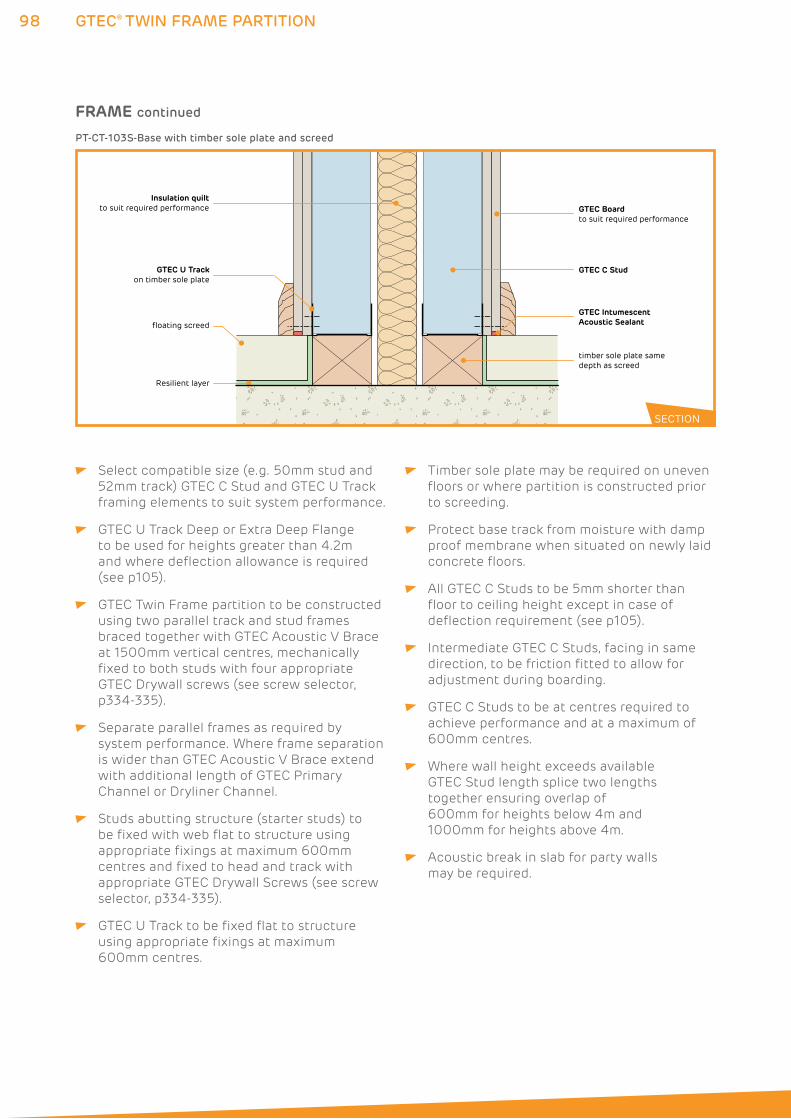
98 GTEC® TWIN FRAME PARTITION
Select compatible size (e.g. 50mm stud and
52mm track) GTEC C Stud and GTEC U Track
framing elements to suit system performance.
GTEC U Track Deep or Extra Deep Flange
to be used for heights greater than 4.2m
and where deflection allowance is required
(see p105).
GTEC Twin Frame partition to be constructed
using two parallel track and stud frames
braced together with GTEC Acoustic V Brace
at 1500mm vertical centres, mechanically
fixed to both studs with four appropriate
GTEC Drywall screws (see screw selector,
p334-335).
Separate parallel frames as required by
system performance. Where frame separation
is wider than GTEC Acoustic V Brace extend
with additional length of GTEC Primary
Channel or Dryliner Channel.
Studs abutting structure (starter studs) to
be fixed with web flat to structure using
appropriate fixings at maximum 600mm
centres and fixed to head and track with
appropriate GTEC Drywall Screws (see screw
selector, p334-335).
GTEC U Track to be fixed flat to structure
using appropriate fixings at maximum
600mm centres.
Timber sole plate may be required on uneven
floors or where partition is constructed prior
to screeding.
Protect base track from moisture with damp
proof membrane when situated on newly laid
concrete floors.
All GTEC C Studs to be 5mm shorter than
floor to ceiling height except in case of
deflection requirement (see p105).
Intermediate GTEC C Studs, facing in same
direction, to be friction fitted to allow for
adjustment during boarding.
GTEC C Studs to be at centres required to
achieve performance and at a maximum of
600mm centres.
Where wall height exceeds available
GTEC Stud length splice two lengths
together ensuring overlap of
600mm for heights below 4m and
1000mm for heights above 4m.
Acoustic break in slab for party walls
may be required.
GTEC Intumescent Acoustic Sealant
GTEC Boardto suit required performance
GTEC C Stud
Insulation quiltto suit required performance
GTEC U Trackon timber sole plate
floating screed
Resilient layer
timber sole plate same depth as screed
PT-CT-103S-Base with timber sole plate and screed
SECTION
FRAME continued
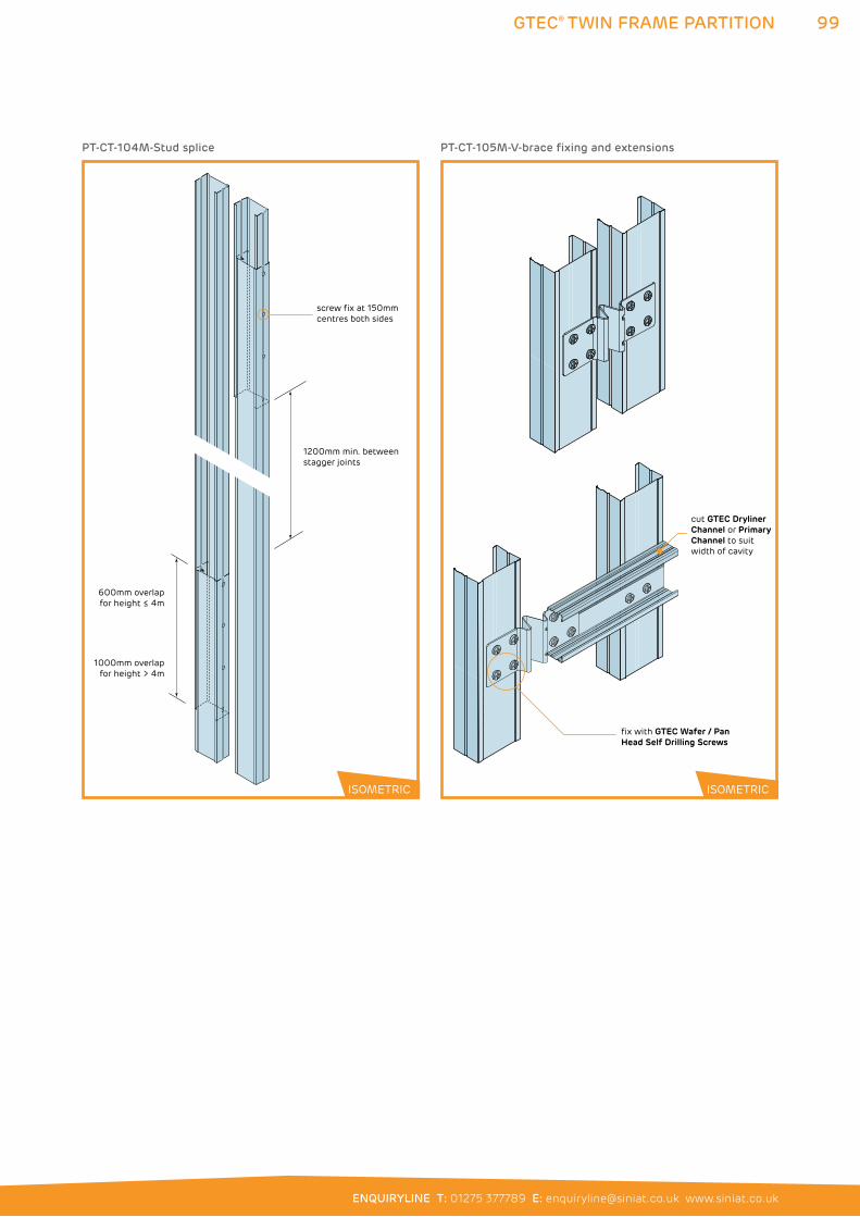
99
ENQUIRYLINE T: 01275 377789 E: [email protected] www.siniat.co.uk
GTEC® TWIN FRAME PARTITION
600mm overlapfor height ≤ 4m
1000mm overlapfor height > 4m
screw fix at 150mm centres both sides
1200mm min. between stagger joints
PT-CT-104M-Stud splice
cut GTEC Dryliner Channel or Primary Channel to suit width of cavity
fix with GTEC Wafer / Pan Head Self Drilling Screws
PT-CT-105M-V-brace fixing and extensions
ISOMETRIC ISOMETRIC
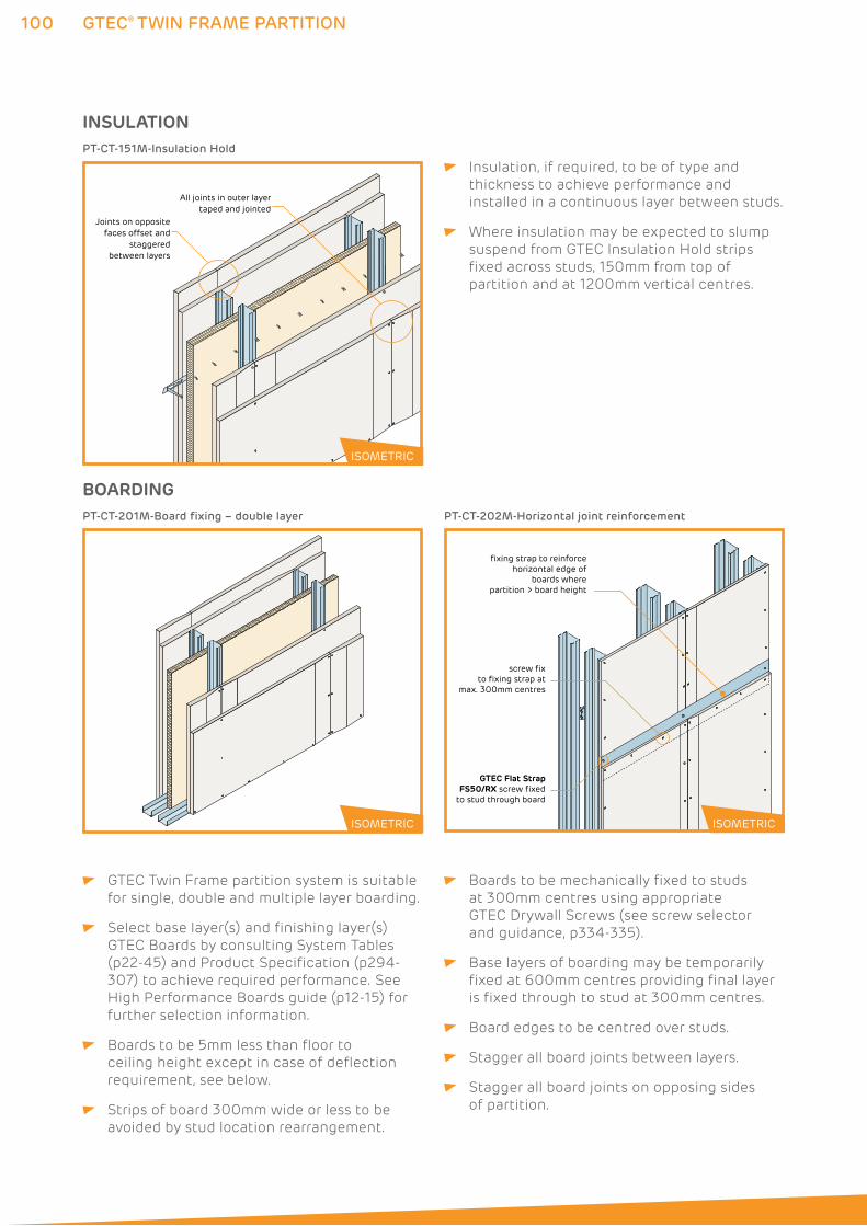
100 GTEC® TWIN FRAME PARTITION
INSULATION
All joints in outer layertaped and jointed
Joints on opposite faces offset and
staggered between layers
PT-CT-151M-Insulation Hold
Insulation, if required, to be of type and
thickness to achieve performance and
installed in a continuous layer between studs.
Where insulation may be expected to slump
suspend from GTEC Insulation Hold strips
fixed across studs, 150mm from top of
partition and at 1200mm vertical centres.
GTEC Twin Frame partition system is suitable
for single, double and multiple layer boarding.
Select base layer(s) and finishing layer(s)
GTEC Boards by consulting System Tables
(p22-45) and Product Specification (p294-
307) to achieve required performance. See
High Performance Boards guide (p12-15) for
further selection information.
Boards to be 5mm less than floor to
ceiling height except in case of deflection
requirement, see below.
Strips of board 300mm wide or less to be
avoided by stud location rearrangement.
Boards to be mechanically fixed to studs
at 300mm centres using appropriate
GTEC Drywall Screws (see screw selector
and guidance, p334-335).
Base layers of boarding may be temporarily
fixed at 600mm centres providing final layer
is fixed through to stud at 300mm centres.
Board edges to be centred over studs.
Stagger all board joints between layers.
Stagger all board joints on opposing sides
of partition.
ISOMETRIC
BOARDINGPT-CT-201M-Board fixing – double layer
GTEC Flat Strap FS50/RX screw fixed
to stud through board
screw fix to fixing strap at
max. 300mm centres
fixing strap to reinforce horizontal edge of
boards where partition > board height
PT-CT-202M-Horizontal joint reinforcement
ISOMETRIC ISOMETRIC
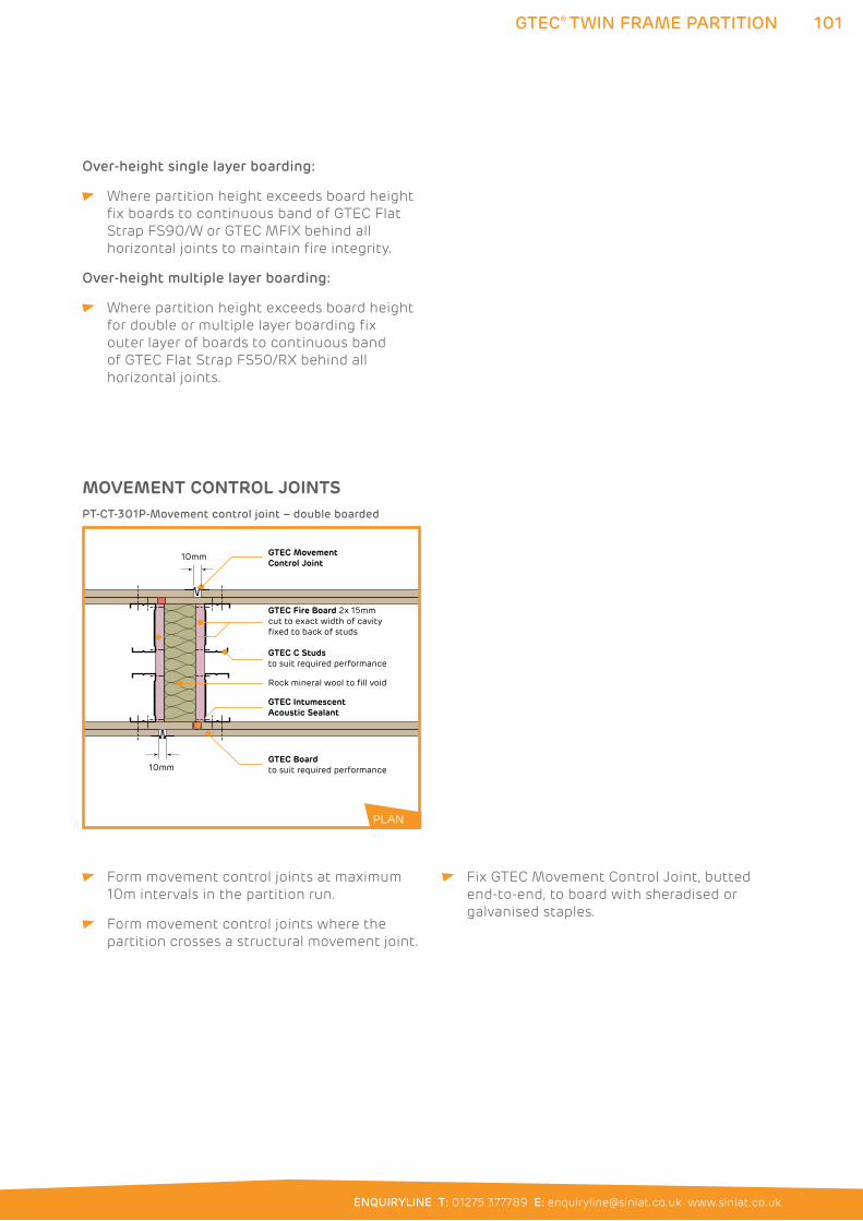
101
ENQUIRYLINE T: 01275 377789 E: [email protected] www.siniat.co.uk
GTEC® TWIN FRAME PARTITION
MOVEMENT CONTROL JOINTS
GTEC Movement Control Joint
Rock mineral wool to fill void
GTEC Fire Board 2x 15mm cut to exact width of cavity fixed to back of studs
GTEC Boardto suit required performance
GTEC C Studsto suit required performance
10mm
10mm
GTEC IntumescentAcoustic Sealant
PT-CT-301P-Movement control joint – double boarded
Form movement control joints at maximum
10m intervals in the partition run.
Form movement control joints where the
partition crosses a structural movement joint.
Fix GTEC Movement Control Joint, butted
end-to-end, to board with sheradised or
galvanised staples.
Over-height single layer boarding:
Where partition height exceeds board height
fix boards to continuous band of GTEC Flat
Strap FS90/W or GTEC MFIX behind all
horizontal joints to maintain fire integrity.
Over-height multiple layer boarding:
Where partition height exceeds board height
for double or multiple layer boarding fix
outer layer of boards to continuous band
of GTEC Flat Strap FS50/RX behind all
horizontal joints.
PLAN
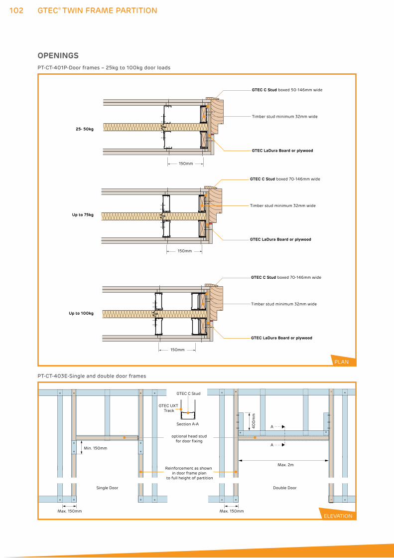
102 GTEC® TWIN FRAME PARTITION
Single Door Double Door
Max. 150mm
Min. 150mm
Section A-A
Reinforcement as shown in door frame plan
to full height of partition
GTEC UXT Track
GTEC C Stud
A
Max. 2m
A40
0m
m
Max. 150mm
optional head studfor door fixing
PT-CT-403E-Single and double door frames
OPENINGS
Timber stud minimum 32mm wide
GTEC C Stud boxed 50-146mm wide
Timber stud minimum 32mm wide
GTEC C Stud boxed 70-146mm wide
GTEC LaDura Board or plywood
GTEC LaDura Board or plywood
GTEC LaDura Board or plywood
Timber stud minimum 32mm wide
GTEC C Stud boxed 70-146mm wide
25- 50kg
Up to 75kg
Up to 100kg
150mm
150mm
150mm
PT-CT-401P-Door frames – 25kg to 100kg door loads
PLAN
ELEVATION
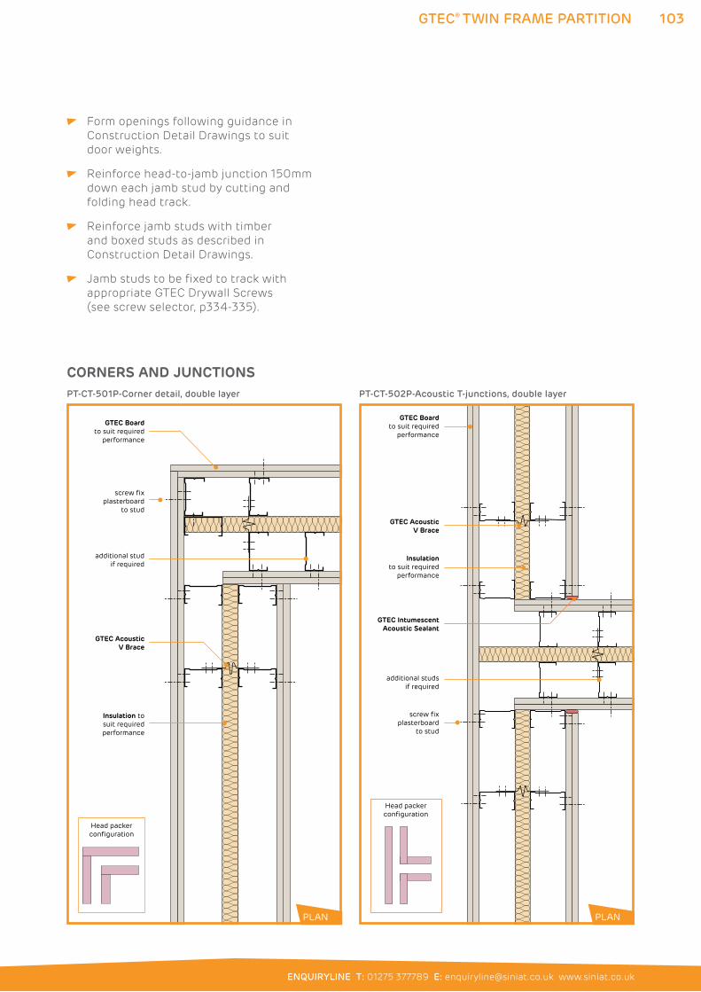
103
ENQUIRYLINE T: 01275 377789 E: [email protected] www.siniat.co.uk
GTEC® TWIN FRAME PARTITION
screw fix plasterboard
to stud
additional stud if required
GTEC AcousticV Brace
GTEC Boardto suit required
performance
Insulation tosuit required
performance
Head packer configuration
PT-CT-501P-Corner detail, double layer
GTEC IntumescentAcoustic Sealant
GTEC Boardto suit required
performance
GTEC Acoustic V Brace
Insulationto suit required
performance
screw fix plasterboard
to stud
additional studs if required
Head packer configuration
PT-CT-502P-Acoustic T-junctions, double layer
Form openings following guidance in
Construction Detail Drawings to suit
door weights.
Reinforce head-to-jamb junction 150mm
down each jamb stud by cutting and
folding head track.
Reinforce jamb studs with timber
and boxed studs as described in
Construction Detail Drawings.
Jamb studs to be fixed to track with
appropriate GTEC Drywall Screws
(see screw selector, p334-335).
CORNERS AND JUNCTIONS
PLAN PLAN
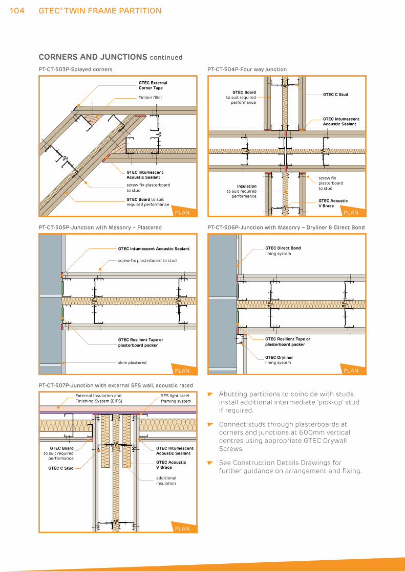
104
GTEC Direct Bondlining system
GTEC Drylinerlining system
GTEC Resilient Tape orplasterboard packer
PLAN
PT-CT-506P-Junction with Masonry – Dryliner & Direct Bond
GTEC® TWIN FRAME PARTITION
Abutting partitions to coincide with studs,
install additional intermediate ‘pick-up’ stud
if required.
Connect studs through plasterboards at
corners and junctions at 600mm vertical
centres using appropriate GTEC Drywall
Screws.
See Construction Details Drawings for
further guidance on arrangement and fixing.
GTEC Intumescent Acoustic Sealant
skim plastered
screw fix plasterboard to stud
GTEC Resilient Tape orplasterboard packer
PLAN
PT-CT-505P-Junction with Masonry – Plastered
External Insulation and Finishing System (EIFS)
SFS light steel framing system
additional insulation
GTEC Intumescent Acoustic Sealant
GTEC C StudGTEC Acoustic V Brace
GTEC Boardto suit required
performance
PT-CT-507P-Junction with external SFS wall, acoustic rated
PLANPLAN
PLAN
PLAN
PLAN
CORNERS AND JUNCTIONS continued
GTEC External Corner Tape
GTEC Board to suit required performance
screw fix plasterboard to stud
Timber fillet
GTEC Intumescent Acoustic Sealant
PT-CT-503P-Splayed corners
screw fix plasterboardto stud
GTEC Boardto suit required
performance
GTEC Intumescent Acoustic Sealant
GTEC C Stud
Insulationto suit required
performanceGTEC Acoustic V Brace
PT-CT-504P-Four way junction
PLAN PLAN
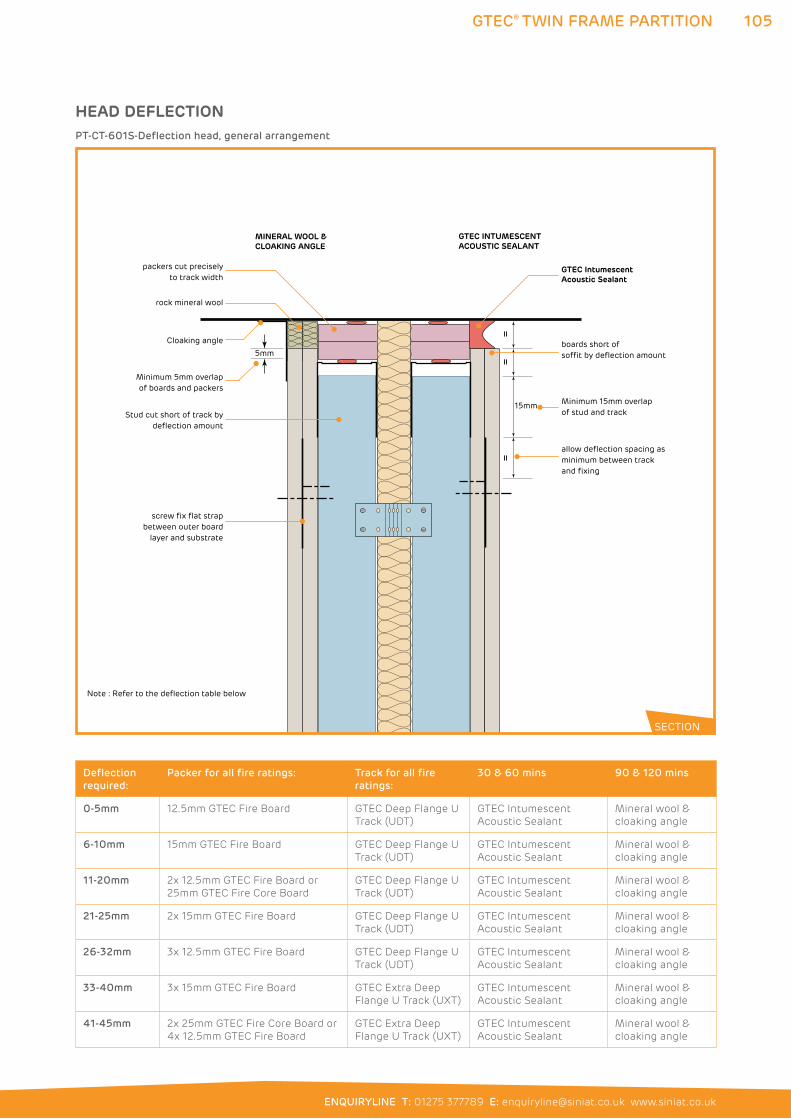
105
ENQUIRYLINE T: 01275 377789 E: [email protected] www.siniat.co.uk
GTEC® TWIN FRAME PARTITION
5mm
==
=
packers cut precisely to track width
Minimum 5mm overlap of boards and packers
Stud cut short of track by deflection amount
Minimum 15mm overlap of stud and track
GTEC IntumescentAcoustic Sealant
screw fix flat strap between outer board
layer and substrate
boards short of soffit by deflection amount
allow deflection spacing as minimum between track and fixing
15mm
MINERAL WOOL &CLOAKING ANGLE
Cloaking angle
rock mineral wool
GTEC INTUMESCENTACOUSTIC SEALANT
Note : Refer to the deflection table below
PT-CT-601S-Deflection head, general arrangement
HEAD DEFLECTION
SECTION
Deflection
required:
Packer for all fire ratings: Track for all fire
ratings:
30 & 60 mins 90 & 120 mins
0-5mm 12.5mm GTEC Fire Board GTEC Deep Flange U
Track (UDT)
GTEC Intumescent
Acoustic Sealant
Mineral wool &
cloaking angle
6-10mm 15mm GTEC Fire Board GTEC Deep Flange U
Track (UDT)
GTEC Intumescent
Acoustic Sealant
Mineral wool &
cloaking angle
11-20mm 2x 12.5mm GTEC Fire Board or
25mm GTEC Fire Core Board
GTEC Deep Flange U
Track (UDT)
GTEC Intumescent
Acoustic Sealant
Mineral wool &
cloaking angle
21-25mm 2x 15mm GTEC Fire Board GTEC Deep Flange U
Track (UDT)
GTEC Intumescent
Acoustic Sealant
Mineral wool &
cloaking angle
26-32mm 3x 12.5mm GTEC Fire Board GTEC Deep Flange U
Track (UDT)
GTEC Intumescent
Acoustic Sealant
Mineral wool &
cloaking angle
33-40mm 3x 15mm GTEC Fire Board GTEC Extra Deep
Flange U Track (UXT)
GTEC Intumescent
Acoustic Sealant
Mineral wool &
cloaking angle
41-45mm 2x 25mm GTEC Fire Core Board or
4x 12.5mm GTEC Fire Board
GTEC Extra Deep
Flange U Track (UXT)
GTEC Intumescent
Acoustic Sealant
Mineral wool &
cloaking angle
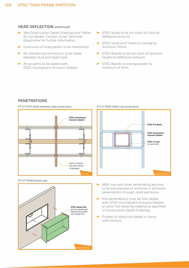
106 GTEC® TWIN FRAME PARTITION
GTEC IntumescentAcoustic Sealant
pipe or conduitless than 50mm in diameter
PT-CT-701P-Small diameter pipe penetration
GTEC Socket Padpre-cut socket pad folded and pushedinto socket box
ISOMETRIC
PT-CT-703M-Socket pad
ELEVATION
GTEC Fire Board
GTEC U Trackcut and bent
GTEC Intumescent Acoustic Sealant
PT-CT-702E-Cable tray penetration
PLAN ELEVATION
PENETRATIONS
ISOMETRIC
M&E runs and other penetrating services
to be pre-planned to minimise or eliminate
penetrations through rated partitions.
Any penetrations must be fully sealed
with GTEC Intumescent Acoustic Sealant
or other fire resisting material as specified
in Construction Detail Drawings.
Protect all electrical cables in cavity
with conduit.
See Construction Detail Drawings and Tables
for full details. Contact Siniat Technical
Enquiryline for further information.
Continuity of head packer to be maintained.
No mechanical connection to be made
between stud and head track.
All air paths to be sealed with
GTEC Intumescent Acoustic Sealant.
GTEC Studs to be cut short of track by
deflection amount.
GTEC Studs and Tracks to overlap by
minimum 30mm.
GTEC Boards to be cut short of partition
height by deflection amount.
GTEC Boards to overlap packer by
minimum of 5mm.
HEAD DEFLECTION continued
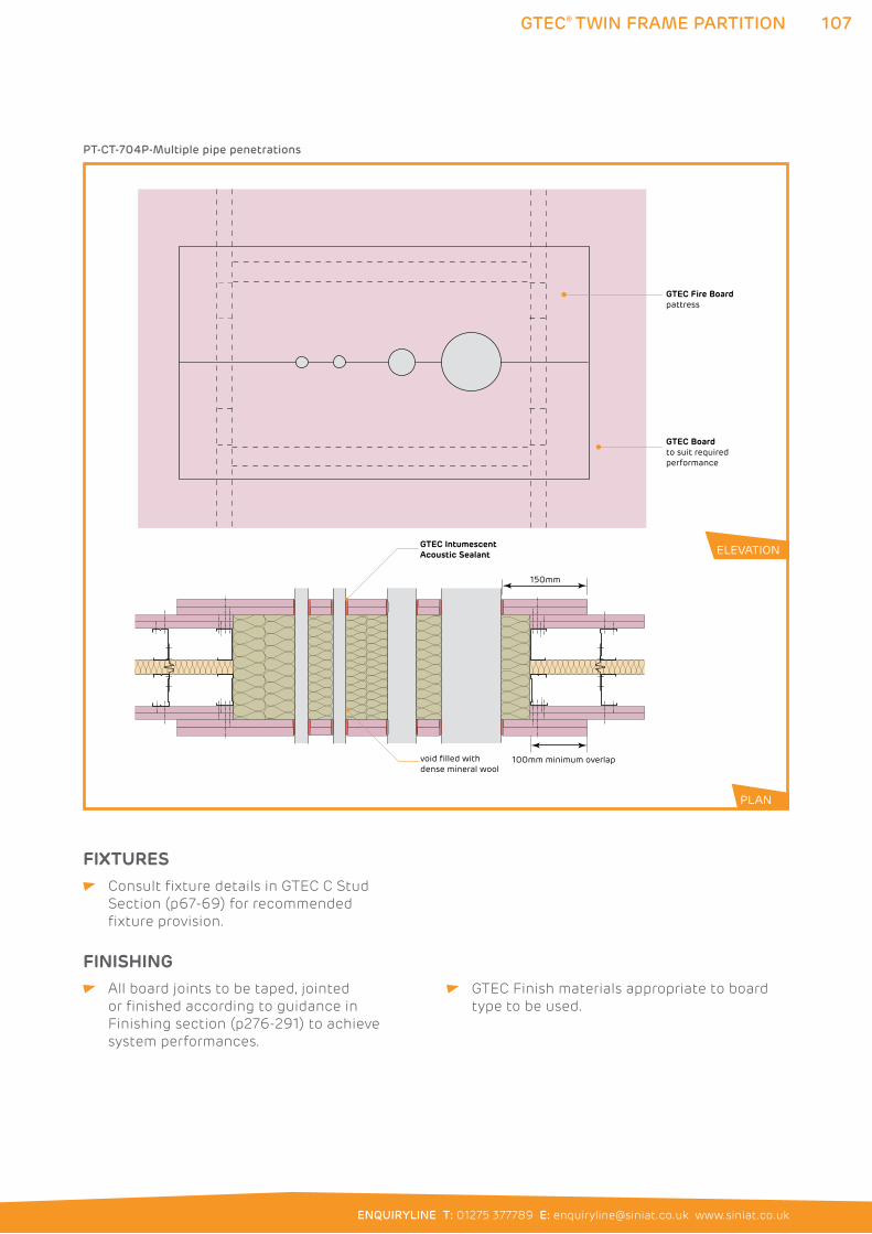
107
ENQUIRYLINE T: 01275 377789 E: [email protected] www.siniat.co.uk
GTEC® TWIN FRAME PARTITION
100mm minimum overlapvoid filled with dense mineral wool
GTEC Intumescent Acoustic Sealant
150mm
GTEC Fire Boardpattress
GTEC Boardto suit required performance
PT-CT-704P-Multiple pipe penetrations
PLAN
ELEVATION
FIXTURES Consult fixture details in GTEC C Stud
Section (p67-69) for recommended
fixture provision.
FINISHING All board joints to be taped, jointed
or finished according to guidance in
Finishing section (p276-291) to achieve
system performances.
GTEC Finish materials appropriate to board
type to be used.
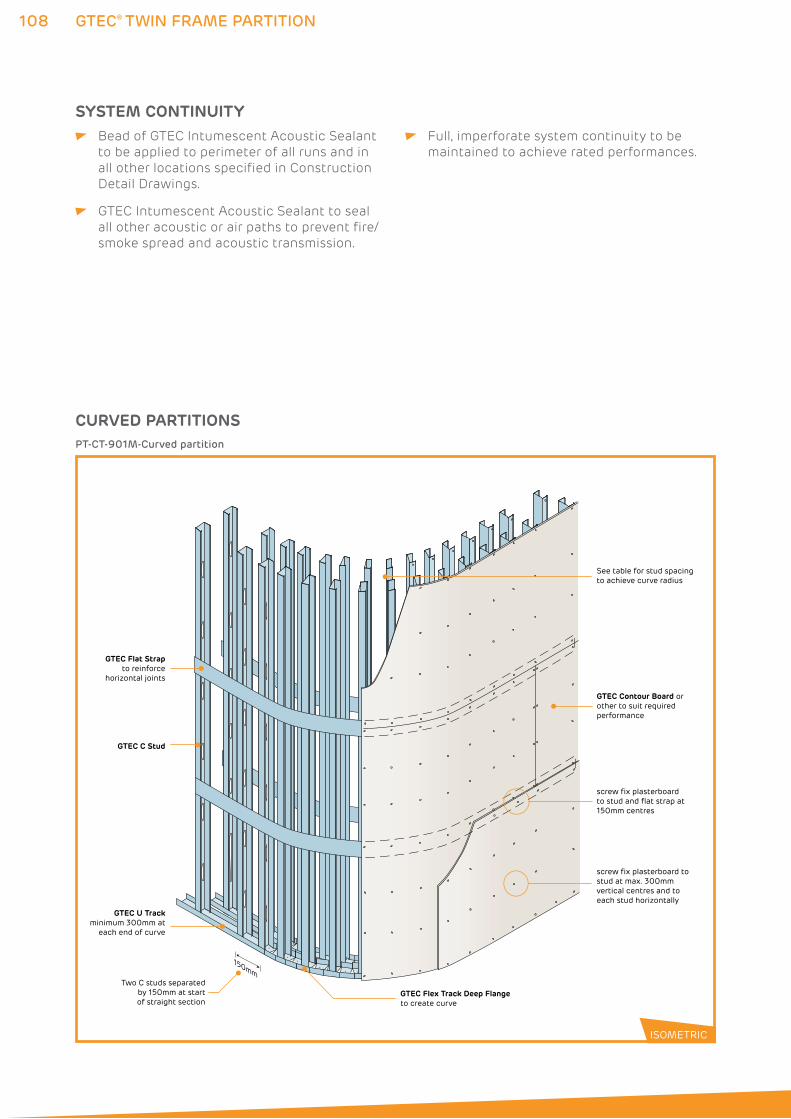
108 GTEC® TWIN FRAME PARTITION
GTEC Flat Strapto reinforce
horizontal joints
GTEC U Trackminimum 300mm at
each end of curve
Two C studs separated by 150mm at start of straight section
GTEC C Stud
GTEC Flex Track Deep Flangeto create curve
GTEC Contour Board or other to suit required performance
screw fix plasterboard to stud and flat strap at 150mm centres
See table for stud spacing to achieve curve radius
150mm
screw fix plasterboard tostud at max. 300mm vertical centres and to each stud horizontally
PT-CT-901M-Curved partition
CURVED PARTITIONS
ISOMETRIC
SYSTEM CONTINUITY Bead of GTEC Intumescent Acoustic Sealant
to be applied to perimeter of all runs and in
all other locations specified in Construction
Detail Drawings.
GTEC Intumescent Acoustic Sealant to seal
all other acoustic or air paths to prevent fire/
smoke spread and acoustic transmission.
Full, imperforate system continuity to be
maintained to achieve rated performances.
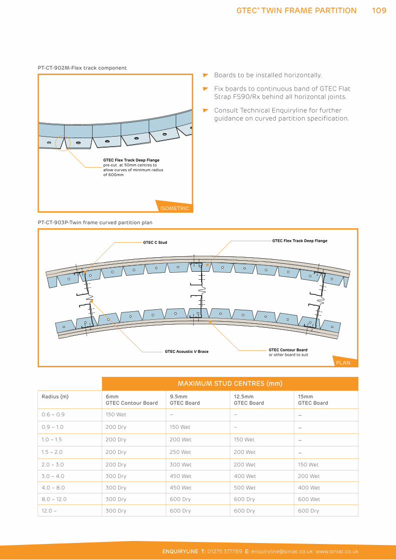
109
ENQUIRYLINE T: 01275 377789 E: [email protected] www.siniat.co.uk
GTEC® TWIN FRAME PARTITION
GTEC Flex Track Deep Flangepre-cut at 50mm centres to allow curves of minimum radius of 600mm
PT-CT-902M-Flex track component
ISOMETRIC
GTEC Flex Track Deep FlangeGTEC C Stud
GTEC Contour Boardor other board to suit
GTEC Acoustic V Brace
PT-CT-903P-Twin frame curved partition plan
PLAN
Boards to be installed horizontally.
Fix boards to continuous band of GTEC Flat
Strap FS90/Rx behind all horizontal joints.
Consult Technical Enquiryline for further
guidance on curved partition specification.
MAXIMUM STUD CENTRES (mm)
Radius (m) 6mm
GTEC Contour Board
9.5mm
GTEC Board
12.5mm
GTEC Board
15mm
GTEC Board
0.6 – 0.9 150 Wet – – –
0.9 – 1.0 200 Dry 150 Wet – –
1.0 – 1.5 200 Dry 200 Wet 150 Wet –
1.5 – 2.0 200 Dry 250 Wet 200 Wet –
2.0 – 3.0 200 Dry 300 Wet 200 Wet 150 Wet
3.0 – 4.0 300 Dry 450 Wet 400 Wet 200 Wet
4.0 – 8.0 300 Dry 450 Wet 500 Wet 400 Wet
8.0 – 12.0 300 Dry 600 Dry 600 Dry 600 Wet
12.0 – 300 Dry 600 Dry 600 Dry 600 Dry
110 GTEC® TIMBER PARTITION
GTEC® TIMBER PARTITION SYSTEMSIn timber frame construction or where traditional methods dominate,
a timber partition may be the preferred construction method.
GTEC Timber Partitions use timber studs and plates in place of metal
framing with GTEC Board screw fixed to complete the partition. Refer
to the System Performance Tables on pages 47 to 49 for full details.
Separating walls can also be constructed with double layers of GTEC
Board and twin timber frames built in parallel to create a separating
cavity. Insulation is applied in between for further sound reduction.
WHERE TO USE: GTEC Timber Partitions are used to create internal and separating
partitions within domestic applications.
FEATURES BENEFITS
Strong Less material required than masonry
construction
GTEC Resilient Bar option Provides improved acoustic performance
Compatible with full range of GTEC boards Achieves excellent partition performance
Flat finish Provides an easy surface for decoration
Cavity space between two frames High levels of acoustic and fire performance
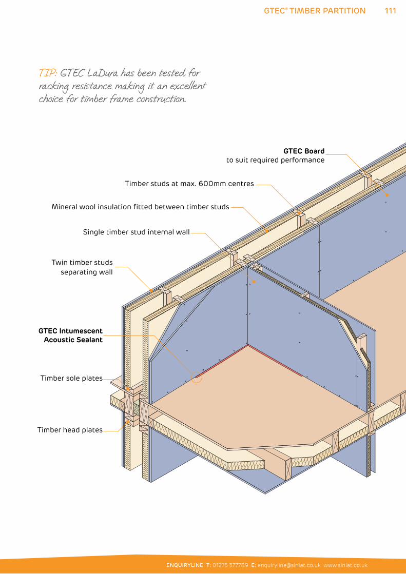
111
ENQUIRYLINE T: 01275 377789 E: [email protected] www.siniat.co.uk
GTEC® TIMBER PARTITION
GTEC IntumescentAcoustic Sealant
GTEC Boardto suit required performance
Timber studs at max. 600mm centres
Twin timber studsseparating wall
Timber sole plates
Timber head plates
Single timber stud internal wall
Mineral wool insulation fitted between timber studs
TIP: GTEC LaDura has been tested for racking resistance making it an excellent choice for timber frame construction.
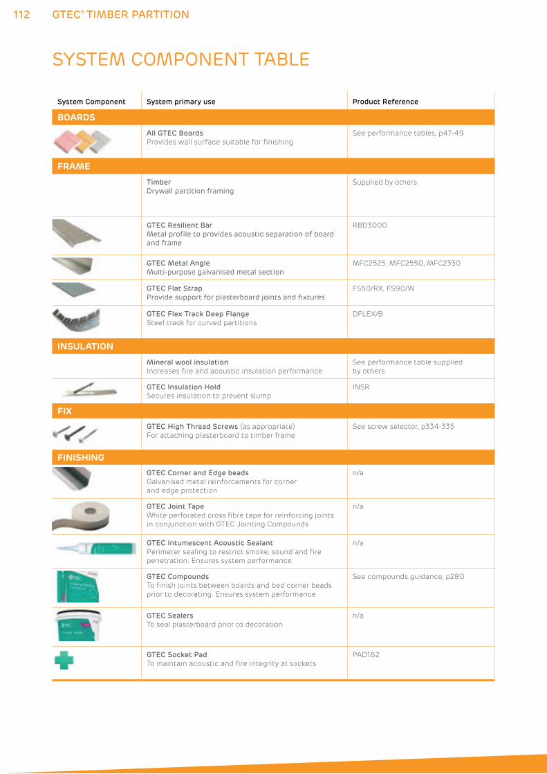
112 GTEC® TIMBER PARTITION
SYSTEM COMPONENT TABLE
System Component System primary use Product Reference
BOARDS
All GTEC Boards
Provides wall surface suitable for finishing
See performance tables, p47-49
FRAME
Timber
Drywall partition framingSupplied by others
GTEC Resilient Bar
Metal profile to provides acoustic separation of board and frame
RBD3000
GTEC Metal Angle
Multi-purpose galvanised metal sectionMFC2525, MFC2550, MFC2330
GTEC Flat Strap
Provide support for plasterboard joints and fixturesFS50/RX, FS90/W
GTEC Flex Track Deep Flange
Steel track for curved partitions
DFLEX/B
INSULATION
Mineral wool insulation
Increases fire and acoustic insulation performance
See performance table supplied
by others
GTEC Insulation Hold
Secures insulation to prevent slump
INSR
FIX
GTEC High Thread Screws (as appropriate)
For attaching plasterboard to timber frame
See screw selector, p334-335
FINISHING
GTEC Corner and Edge beads
Galvanised metal reinforcements for corner
and edge protection
n/a
GTEC Joint Tape
White perforated cross fibre tape for reinforcing joints
in conjunction with GTEC Jointing Compounds
n/a
GTEC Intumescent Acoustic Sealant
Perimeter sealing to restrict smoke, sound and fire
penetration. Ensures system performance
n/a
GTEC Compounds
To finish joints between boards and bed corner beads
prior to decorating. Ensures system performance
See compounds guidance, p280
GTEC Sealers
To seal plasterboard prior to decoration
n/a
GTEC Socket Pad
To maintain acoustic and fire integrity at sockets
PAD1&2
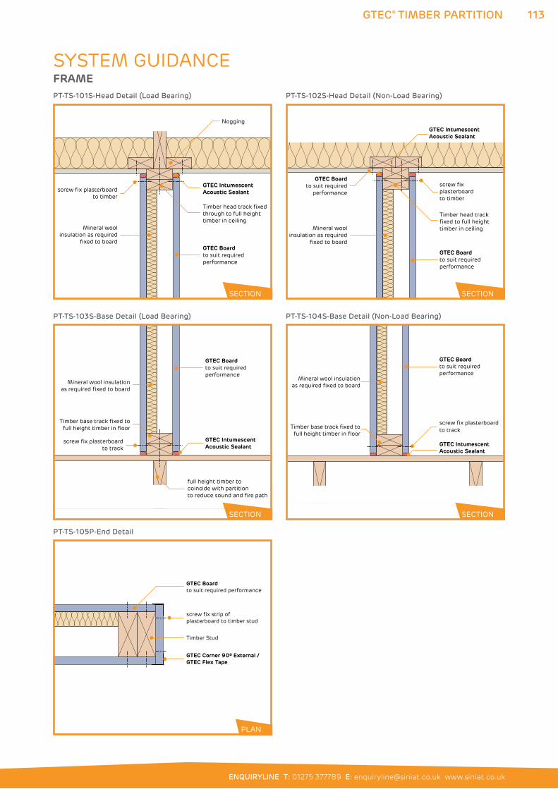
113
ENQUIRYLINE T: 01275 377789 E: [email protected] www.siniat.co.uk
GTEC® TIMBER PARTITION
GTEC Intumescent Acoustic Sealant
screw fix plasterboardto track
GTEC Boardto suit required performance
Timber base track fixed tofull height timber in floor
Mineral wool insulationas required fixed to board
PT-TS-104S-Base Detail (Non-Load Bearing)
SYSTEM GUIDANCEFRAME
screw fix plasterboard to timber
GTEC Intumescent Acoustic Sealant
GTEC Boardto suit required performance
Timber head track fixed through to full height timber in ceiling
Nogging
Mineral woolinsulation as required
fixed to board
PT-TS-101S-Head Detail (Load Bearing)
GTEC Intumescent Acoustic Sealant
screw fix plasterboard to track
GTEC Boardto suit required performance
full height timber to coincide with partition to reduce sound and fire path
Timber base track fixed tofull height timber in floor
Mineral wool insulationas required fixed to board
PT-TS-103S-Base Detail (Load Bearing)
Timber Stud
GTEC Boardto suit required performance
screw fix strip of plasterboard to timber stud
GTEC Corner 90º External /GTEC Flex Tape
PT-TS-105P-End Detail
screw fix plasterboard to timber
GTEC IntumescentAcoustic Sealant
GTEC Boardto suit required performance
Timber head track fixed to full height timber in ceiling
GTEC Boardto suit required
performance
Mineral woolinsulation as required
fixed to board
PT-TS-102S-Head Detail (Non-Load Bearing)
SECTION
SECTION SECTION
SECTION
PLAN
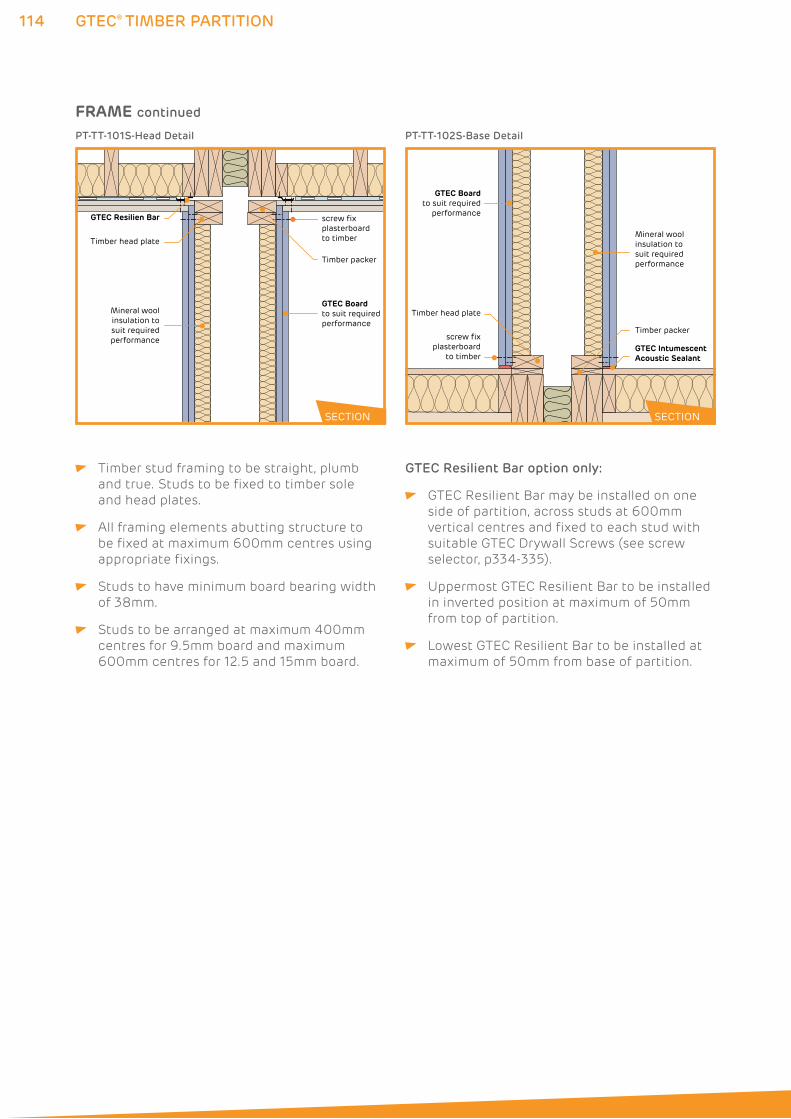
114 GTEC® TIMBER PARTITION
GTEC Boardto suit required performance
screw fix plasterboard to timber
Timber packer
Timber head plate
Mineral woolinsulation tosuit requiredperformance
GTEC Resilien Bar
PT-TT-101S-Head Detail
GTEC Boardto suit required
performance
screw fix plasterboard
to timber GTEC Intumescent Acoustic Sealant
Timber packer
Timber head plate
Mineral woolinsulation to suit required performance
PT-TT-102S-Base Detail
SECTION SECTION
Timber stud framing to be straight, plumb
and true. Studs to be fixed to timber sole
and head plates.
All framing elements abutting structure to
be fixed at maximum 600mm centres using
appropriate fixings.
Studs to have minimum board bearing width
of 38mm.
Studs to be arranged at maximum 400mm
centres for 9.5mm board and maximum
600mm centres for 12.5 and 15mm board.
GTEC Resilient Bar option only:
GTEC Resilient Bar may be installed on one
side of partition, across studs at 600mm
vertical centres and fixed to each stud with
suitable GTEC Drywall Screws (see screw
selector, p334-335).
Uppermost GTEC Resilient Bar to be installed
in inverted position at maximum of 50mm
from top of partition.
Lowest GTEC Resilient Bar to be installed at
maximum of 50mm from base of partition.
FRAME continued
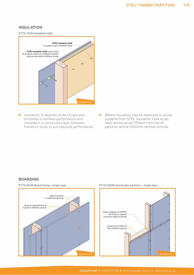
115
ENQUIRYLINE T: 01275 377789 E: [email protected] www.siniat.co.uk
GTEC® TIMBER PARTITION
GTEC Insulation Holdto support each insulation batt
GTEC Insulation Hold screw fixed to studs at maximum 1200mm vertical
centres and within 600mm of top
PT-TS-151M-Insulation Hold
ISOMETRIC
INSULATION
Insulation, if required, to be of type and
thickness to achieve performance and
installed in a continuous layer between
frames or studs to suit required performance.
Where insulation may be expected to slump
suspend from GTEC Insulation Hold strips
fixed across studs, 150mm from top of
partition and at 1200mm vertical centres.
opposing jointson alternating studs
screw fix plasterboard atmaximum 300mm centres
PT-TS-201M-Board fixing – single layer
timber nogging or FS90/W flat strap to support
horizontal edge of boards
screw fix to timber at max. 300mm centres
PT-TS-202M-Overheight partition – single layer
ISOMETRIC ISOMETRIC
BOARDING
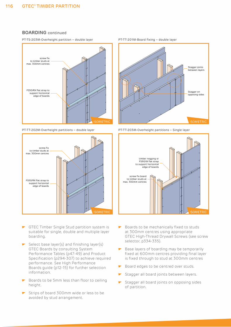
116 GTEC® TIMBER PARTITION
GTEC Timber Single Stud partition system is
suitable for single, double and multiple layer
boarding.
Select base layer(s) and finishing layer(s)
GTEC Boards by consulting System
Performance Tables (p47-49) and Product
Specification (p294-307) to achieve required
performance. See High Performance
Boards guide (p12-15) for further selection
information.
Boards to be 5mm less than floor to ceiling
height.
Strips of board 300mm wide or less to be
avoided by stud arrangement.
Boards to be mechanically fixed to studs
at 300mm centres using appropriate
GTEC High-Thread Drywall Screws (see screw
selector, p334-335).
Base layers of boarding may be temporarily
fixed at 600mm centres providing final layer
is fixed through to stud at 300mm centres
Board edges to be centred over studs.
Stagger all board joints between layers.
Stagger all board joints on opposing sides
of partition.
Stagger jointsbetween layers
Stagger on opposing sides
PT-TT-201M-Board fixing – double layer
timber nogging or FS90/W flat strap
to support horizontal edge of boards
screw fix board to timber studs at
max. 300mm centres
PT-TT-203M-Overheight partitions – Single layer
screw fix to timber studs at
max. 300mm centres
FS50/RX flat strap to support horizontal
edge of boards
PT-TS-203M-Overheight partition – double layer
screw fix to timber studs at
max. 300mm centres
FS50/RX flat strap to support horizontal
edge of boards
PT-TT-202M-Overheight partitions – double layer
ISOMETRIC
ISOMETRIC
ISOMETRIC
ISOMETRIC
BOARDING continued
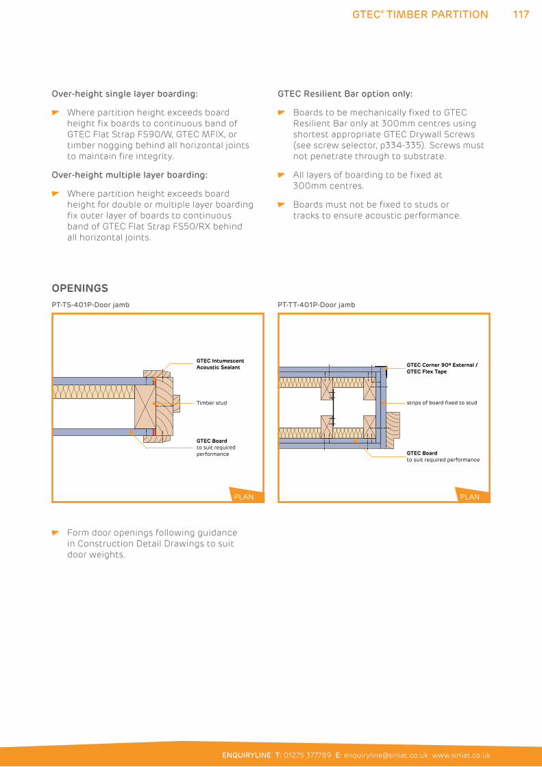
117
ENQUIRYLINE T: 01275 377789 E: [email protected] www.siniat.co.uk
GTEC® TIMBER PARTITION
Over-height single layer boarding:
Where partition height exceeds board
height fix boards to continuous band of
GTEC Flat Strap FS90/W, GTEC MFIX, or
timber nogging behind all horizontal joints
to maintain fire integrity.
Over-height multiple layer boarding:
Where partition height exceeds board
height for double or multiple layer boarding
fix outer layer of boards to continuous
band of GTEC Flat Strap FS50/RX behind
all horizontal joints.
GTEC Resilient Bar option only:
Boards to be mechanically fixed to GTEC
Resilient Bar only at 300mm centres using
shortest appropriate GTEC Drywall Screws
(see screw selector, p334-335). Screws must
not penetrate through to substrate.
All layers of boarding to be fixed at
300mm centres.
Boards must not be fixed to studs or
tracks to ensure acoustic performance.
Form door openings following guidance
in Construction Detail Drawings to suit
door weights.
GTEC Intumescent Acoustic Sealant
Timber stud
GTEC Boardto suit required performance
PT-TS-401P-Door jamb
strips of board fixed to stud
GTEC Boardto suit required performance
GTEC Corner 90º External /GTEC Flex Tape
PT-TT-401P-Door jamb
PLANPLAN
OPENINGS
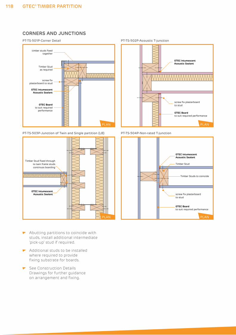
118
GTEC IntumescentAcoustic Sealant
GTEC Boardto suit required
performance
Timber Stud as required
screw fix plasterboard to stud
timber studs fixed together
PT-TS-501P-Corner Detail
GTEC IntumescentAcoustic Sealant
Timber Stud fixed throughto twin frame studscontinuos boarding
PT-TS-503P-Junction of Twin and Single partition (LB)
GTEC® TIMBER PARTITION
PLAN
PLAN
GTEC Intumescent Acoustic Sealant
screw fix plasterboardto stud
GTEC Boardto suit required performance
PT-TS-502P-Acoustic T-junction
CORNERS AND JUNCTIONS
PLAN
Abutting partitions to coincide with
studs, install additional intermediate
‘pick-up’ stud if required.
Additional studs to be installed
where required to provide
fixing substrate for boards.
See Construction Details
Drawings for further guidance
on arrangement and fixing.
GTEC Intumescent Acoustic Sealant
screw fix plasterboard to stud
GTEC Boardto suit required performance
Timber Stud
Timber Studs to coincide
PT-TS-504P-Non-rated T-junction
PLAN
119
ENQUIRYLINE T: 01275 377789 E: [email protected] www.siniat.co.uk
GTEC® TIMBER PARTITION
FIXTURES See guidance on p67-69 for further information.
FINISHING All board joints to be taped, jointed
or finished according to guidance in
Finishing section (p276-291) to achieve
system performances.
GTEC Finish materials appropriate to
board type to be used.
HEAD DEFLECTION Timber stud partitions are not generally
compatible with deflection head requirements.
PENETRATIONS M&E runs and other penetrating services
to be pre-planned to minimise or eliminate
penetrations through rated partitions.
Any penetrations must be fully sealed
with GTEC Intumescent Acoustic Sealant
or other fire resisting material as specified
in Construction Detail Drawings.
Protect all electrical cables in cavity
with conduit.
SYSTEM CONTINUITY Bead of GTEC Intumescent Acoustic Sealant
to be applied to perimeter of all runs and in
all other locations specified in Construction
Detail Drawings.
GTEC Intumescent Acoustic Sealant to seal
all other acoustic or air paths to prevent fire/
smoke spread and acoustic transmission.
Full, imperforate system continuity to be
maintained to achieve rated performances.
GTEC® FLOORS AND CEILINGS120
121
ENQUIRYLINE T: 01275 377789 E: [email protected] www.siniat.co.uk
FLOORS AND CEILINGSGTEC Floor and Ceiling systems are used to achieve acoustic and fire rated solutions for both domestic and commercial building projects.
A range of solutions are available; from direct soffit application to the creation of full supporting frames. They are suitable for varying building projects and can be built in large runs.
System Performance Tables
GTEC Engineered Joist Systems 122
GTEC Ceiling Systems to Timber Floors 123
GTEC Dryliner Ceiling Systems to Concrete Soffit 127
GTEC Separating Floor Systems 128
GTEC Pregybel MF Ceiling Systems 131
GTEC Suspended MF Ceiling Systems to Timber Floors 133
GTEC Suspended MF Ceiling Systems to Protect Structure 135
GTEC Mass Barrier Ceilings 136
GTEC Acoustic Floor Systems 137
GTEC Suspended MF Ceiling 138
GTEC Pregybel MF Ceiling 148
GTEC Dryliner Ceiling 154
GTEC Direct-to-Timber Ceiling 162
GTEC Acoustic Floor 170
121
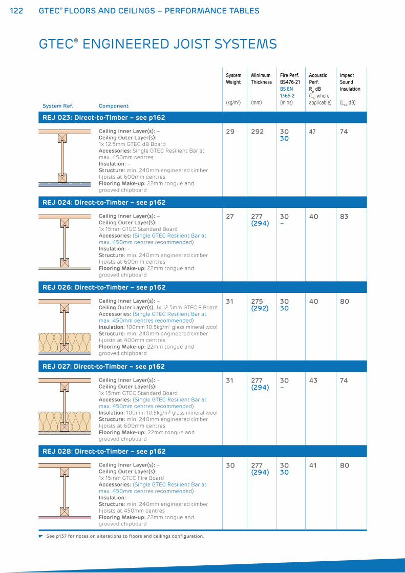
122 GTEC® FLOORS AND CEILINGS – PERFORMANCE TABLES
System Ref. Component
System
Weight
(kg/m2)
Minimum
Thickness
(mm)
Fire Perf.
BS476-21
BS EN
1365-2
(mins)
Acoustic
Perf.
Rw dB
(Ctr where
applicable)
Impact
Sound
Insulation
(Lnw
dB)
REJ 023: Direct-to-Timber – see p162
Ceiling Inner Layer(s): –
Ceiling Outer Layer(s):
1x 12.5mm GTEC dB Board
Accessories: Single GTEC Resilient Bar at
max. 450mm centres
Insulation: –
Structure: min. 240mm engineered timber
I-joists at 600mm centres
Flooring Make-up: 22mm tongue and
grooved chipboard
29 292 3030
47 74
REJ 024: Direct-to-Timber – see p162
Ceiling Inner Layer(s): –
Ceiling Outer Layer(s):
1x 15mm GTEC Standard Board
Accessories: (Single GTEC Resilient Bar at
max. 450mm centres recommended)
Insulation: –
Structure: min. 240mm engineered timber
I-joists at 600mm centres
Flooring Make-up: 22mm tongue and
grooved chipboard
27 277(294)
30–
40 83
REJ 026: Direct-to-Timber – see p162
Ceiling Inner Layer(s): –
Ceiling Outer Layer(s): 1x 12.5mm GTEC E Board
Accessories: (Single GTEC Resilient Bar at
max. 450mm centres recommended)
Insulation: 100mm 10.5kg/m3 glass mineral wool
Structure: min. 240mm engineered timber
I-joists at 400mm centres
Flooring Make-up: 22mm tongue and
grooved chipboard
31 275(292)
3030
40 80
REJ 027: Direct-to-Timber – see p162
Ceiling Inner Layer(s): –
Ceiling Outer Layer(s):
1x 15mm GTEC Standard Board
Accessories: (Single GTEC Resilient Bar at
max. 450mm centres recommended)
Insulation: 100mm 10.5kg/m3 glass mineral wool
Structure: min. 240mm engineered timber
I-joists at 600mm centres
Flooring Make-up: 22mm tongue and
grooved chipboard
31 277(294)
30–
43 74
REJ 028: Direct-to-Timber – see p162
Ceiling Inner Layer(s): –
Ceiling Outer Layer(s):
1x 15mm GTEC Fire Board
Accessories: (Single GTEC Resilient Bar at
max. 450mm centres recommended)
Insulation: –
Structure: min. 240mm engineered timber
I-joists at 450mm centres
Flooring Make-up: 22mm tongue and
grooved chipboard
30 277(294)
3030
41 80
GTEC® ENGINEERED JOIST SYSTEMS
See p137 for notes on alterations to floors and ceilings configuration.
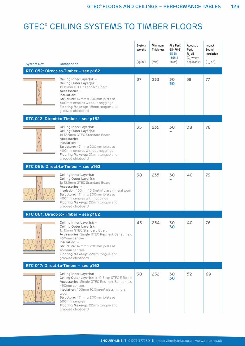
123GTEC® FLOORS AND CEILINGS – PERFORMANCE TABLES
ENQUIRYLINE T: 01275 377789 E: [email protected] www.siniat.co.uk
System Ref. Component
System
Weight
(kg/m2)
Minimum
Thickness
(mm)
Fire Perf.
BS476-21
BS EN
1365-2
(mins)
Acoustic
Perf.
Rw dB
(Ctr where
applicable)
Impact
Sound
Insulation
(Lnw
dB)
RTC 052: Direct-to-Timber – see p162
Ceiling Inner Layer(s): –
Ceiling Outer Layer(s):
1x 15mm GTEC Standard Board
Accessories: –
Insulation: –
Structure: 47mm x 200mm joists at
400mm centres without noggings
Flooring Make-up: 18mm tongue and
grooved chipboard
37 233 3030
38 77
RTC 012: Direct-to-Timber – see p162
Ceiling Inner Layer(s): –
Ceiling Outer Layer(s):
1x 12.5mm GTEC Standard Board
Accessories: –
Insulation: –
Structure: 47mm x 200mm joists at
400mm centres without noggings
Flooring Make-up: 22mm tongue and
grooved chipboard
35 235 30–
38 78
RTC 065: Direct-to-Timber – see p162
Ceiling Inner Layer(s): –
Ceiling Outer Layer(s):
1x 12.5mm GTEC Standard Board
Accessories: –
Insulation: 100mm 10.5kg/m3 glass mineral wool
Structure: 47mm x 200mm joists at
400mm centres with noggings
Flooring Make-up: 22mm tongue and
grooved chipboard
38 235 30–
40 79
RTC 061: Direct-to-Timber – see p162
Ceiling Inner Layer(s): –
Ceiling Outer Layer(s):
1x 15mm GTEC Standard Board
Accessories: Single GTEC Resilient Bar at max.
450mm centres
Insulation: –
Structure: 47mm x 200mm joists at
450mm centres
Flooring Make-up: 22mm tongue and
grooved chipboard
43 254 3030
40 76
RTC 017: Direct-to-Timber – see p162
Ceiling Inner Layer(s): –
Ceiling Outer Layer(s): 1x 12.5mm GTEC E Board
Accessories: Single GTEC Resilient Bar at max.
450mm centres
Insulation: 100mm 10.5kg/m3 glass mineral
wool
Structure: 47mm x 200mm joists at
600mm centres
Flooring Make-up: 22mm tongue and
grooved chipboard
38 252 3030
52 69
GTEC® CEILING SYSTEMS TO TIMBER FLOORS
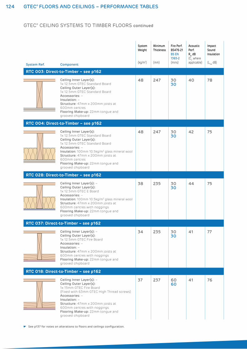
124 GTEC® FLOORS AND CEILINGS – PERFORMANCE TABLES
System Ref. Component
System
Weight
(kg/m2)
Minimum
Thickness
(mm)
Fire Perf.
BS476-21
BS EN
1365-2
(mins)
Acoustic
Perf.
Rw dB
(Ctr where
applicable)
Impact
Sound
Insulation
(Lnw
dB)
RTC 003: Direct-to-Timber – see p162
Ceiling Inner Layer(s):
1x 12.5mm GTEC Standard Board
Ceiling Outer Layer(s):
1x 12.5mm GTEC Standard Board
Accessories: –
Insulation: –
Structure: 47mm x 200mm joists at
600mm centres
Flooring Make-up: 22mm tongue and
grooved chipboard
48 247 3030
40 78
RTC 004: Direct-to-Timber – see p162
Ceiling Inner Layer(s):
1x 12.5mm GTEC Standard Board
Ceiling Outer Layer(s):
1x 12.5mm GTEC Standard Board
Accessories: –
Insulation: 100mm 10.5kg/m3 glass mineral wool
Structure: 47mm x 200mm joists at
600mm centres
Flooring Make-up: 22mm tongue and
grooved chipboard
48 247 3030
42 75
RTC 028: Direct-to-Timber – see p162
Ceiling Inner Layer(s): –
Ceiling Outer Layer(s):
1x 12.5mm GTEC E Board
Accessories: –
Insulation: 100mm 10.5kg/m3 glass mineral wool
Structure: 47mm x 200mm joists at
600mm centres with noggings
Flooring Make-up: 22mm tongue and
grooved chipboard
38 235 3030
44 75
RTC 037: Direct-to-Timber – see p162
Ceiling Inner Layer(s): –
Ceiling Outer Layer(s):
1x 12.5mm GTEC Fire Board
Accessories: –
Insulation: –
Structure: 47mm x 200mm joists at
600mm centres with noggings
Flooring Make-up: 22mm tongue and
grooved chipboard
34 235 3030
41 77
RTC 018: Direct-to-Timber – see p162
Ceiling Inner Layer(s): –
Ceiling Outer Layer(s):
1x 15mm GTEC Fire Board
(Fixed with 63mm GTEC High Thread screws)
Accessories: –
Insulation: –
Structure: 47mm x 200mm joists at
600mm centres with noggings
Flooring Make-up: 22mm tongue and
grooved chipboard
37 237 6060
41 76
GTEC® CEILING SYSTEMS TO TIMBER FLOORS continued
See p137 for notes on alterations to floors and ceilings configuration.
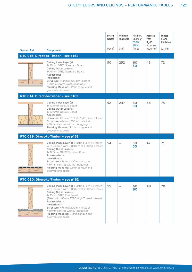
125GTEC® FLOORS AND CEILINGS – PERFORMANCE TABLES
ENQUIRYLINE T: 01275 377789 E: [email protected] www.siniat.co.uk
System Ref. Component
System
Weight
(kg/m2)
Minimum
Thickness
(mm)
Fire Perf.
BS476-21
BS EN
1365-2
(mins)
Acoustic
Perf.
Rw dB
(Ctr where
applicable)
Impact
Sound
Insulation
(Lnw
dB)
RTC 016: Direct-to-Timber – see p162
Ceiling Inner Layer(s):
1x 15mm GTEC Standard Board
Ceiling Outer Layer(s):
1x 15mm GTEC Standard Board
Accessories: –
Insulation: –
Structure: 47mm x 200mm joists at
600mm centres with noggings
Flooring Make-up: 22mm tongue and
grooved chipboard
50 252 6030
43 72
RTC 014: Direct-to-Timber – see p162
Ceiling Inner Layer(s):
1x 12.5mm GTEC E Board
Ceiling Outer Layer(s):
1x 12.5mm GTEC E Board
Accessories: –
Insulation: 100mm 10.5kg/m3 glass mineral wool
Structure: 47mm x 200mm joists at
450mm centres without noggings
Flooring Make-up: 22mm tongue and
grooved chipboard
52 247 3030
44 75
RTC 029: Direct-to-Timber – see p162
Ceiling Inner Layer(s): Existing Lath & Plaster
with Chicken Wire & Battens at 400mm centres
Ceiling Outer Layer(s):
1x 12.5mm GTEC Standard Board
Accessories: –
Insulation: –
Structure: 47mm x 200mm joists at
450mm centres without noggings
Flooring Make-up: 22mm tongue and
grooved chipboard
54 – 3030
47 71
RTC 020: Direct-to-Timber – see p162
Ceiling Inner Layer(s): Existing Lath & Plaster
with Chicken Wire & Battens at 400mm centres
Ceiling Outer Layer(s):
1x 15mm GTEC Fire Board
(Fixed with 63mm GTEC High Thread screws)
Accessories: –
Insulation: –
Structure: 47mm x 200mm joists at
450mm centres without noggings
Flooring Make-up: 22mm tongue and
grooved chipboard
55 – 6060
48 70
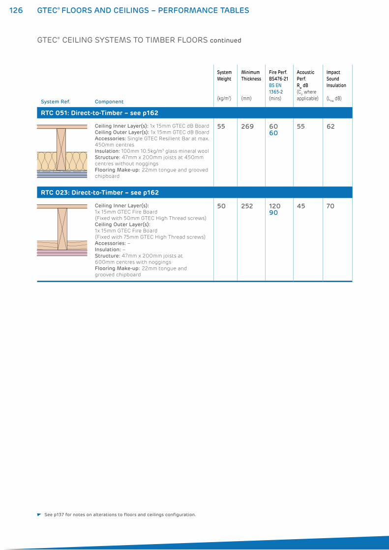
126 GTEC® FLOORS AND CEILINGS – PERFORMANCE TABLES
System Ref. Component
System
Weight
(kg/m2)
Minimum
Thickness
(mm)
Fire Perf.
BS476-21
BS EN
1365-2
(mins)
Acoustic
Perf.
Rw dB
(Ctr where
applicable)
Impact
Sound
Insulation
(Lnw
dB)
RTC 051: Direct-to-Timber – see p162
Ceiling Inner Layer(s): 1x 15mm GTEC dB Board
Ceiling Outer Layer(s): 1x 15mm GTEC dB Board
Accessories: Single GTEC Resilient Bar at max.
450mm centres
Insulation: 100mm 10.5kg/m3 glass mineral wool
Structure: 47mm x 200mm joists at 450mm
centres without noggings
Flooring Make-up: 22mm tongue and grooved
chipboard
55 269 6060
55 62
RTC 023: Direct-to-Timber – see p162
Ceiling Inner Layer(s):
1x 15mm GTEC Fire Board
(Fixed with 50mm GTEC High Thread screws)
Ceiling Outer Layer(s):
1x 15mm GTEC Fire Board
(Fixed with 75mm GTEC High Thread screws)
Accessories: –
Insulation: –
Structure: 47mm x 200mm joists at
600mm centres with noggings
Flooring Make-up: 22mm tongue and
grooved chipboard
50 252 12090
45 70
GTEC® CEILING SYSTEMS TO TIMBER FLOORS continued
See p137 for notes on alterations to floors and ceilings configuration.
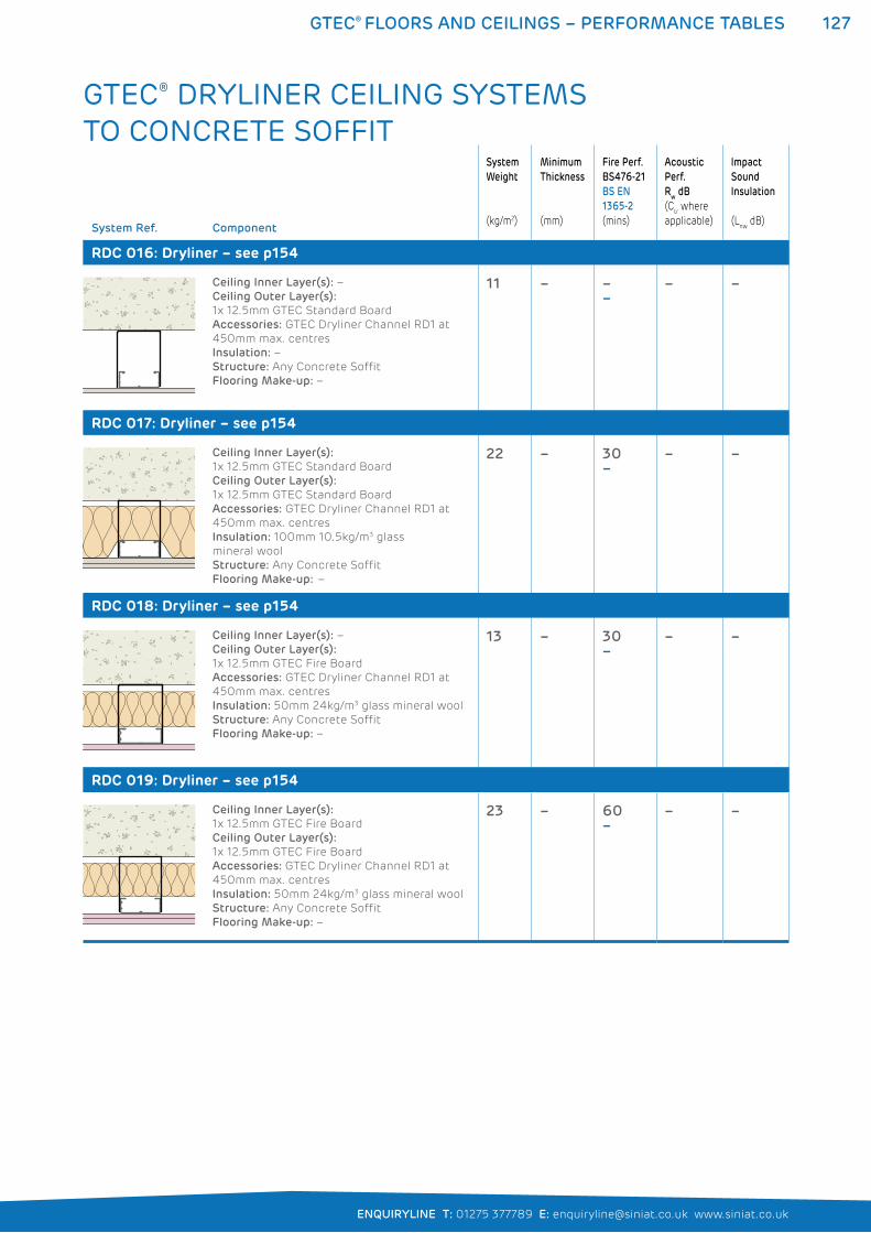
127GTEC® FLOORS AND CEILINGS – PERFORMANCE TABLES
ENQUIRYLINE T: 01275 377789 E: [email protected] www.siniat.co.uk
System Ref. Component
System
Weight
(kg/m2)
Minimum
Thickness
(mm)
Fire Perf.
BS476-21
BS EN
1365-2
(mins)
Acoustic
Perf.
Rw dB
(Ctr where
applicable)
Impact
Sound
Insulation
(Lnw
dB)
RDC 016: Dryliner – see p154
Ceiling Inner Layer(s): –
Ceiling Outer Layer(s):
1x 12.5mm GTEC Standard Board
Accessories: GTEC Dryliner Channel RD1 at
450mm max. centres
Insulation: –
Structure: Any Concrete Soffit
Flooring Make-up: –
11 – ––
– –
RDC 017: Dryliner – see p154
Ceiling Inner Layer(s):
1x 12.5mm GTEC Standard Board
Ceiling Outer Layer(s):
1x 12.5mm GTEC Standard Board
Accessories: GTEC Dryliner Channel RD1 at
450mm max. centres
Insulation: 100mm 10.5kg/m3 glass
mineral wool
Structure: Any Concrete Soffit
Flooring Make-up: –
22 – 30–
– –
RDC 018: Dryliner – see p154
Ceiling Inner Layer(s): –
Ceiling Outer Layer(s):
1x 12.5mm GTEC Fire Board
Accessories: GTEC Dryliner Channel RD1 at
450mm max. centres
Insulation: 50mm 24kg/m3 glass mineral wool
Structure: Any Concrete Soffit
Flooring Make-up: –
13 – 30–
– –
RDC 019: Dryliner – see p154
Ceiling Inner Layer(s):
1x 12.5mm GTEC Fire Board
Ceiling Outer Layer(s):
1x 12.5mm GTEC Fire Board
Accessories: GTEC Dryliner Channel RD1 at
450mm max. centres
Insulation: 50mm 24kg/m3 glass mineral wool
Structure: Any Concrete Soffit
Flooring Make-up: –
23 – 60–
– –
GTEC® DRYLINER CEILING SYSTEMS TO CONCRETE SOFFIT
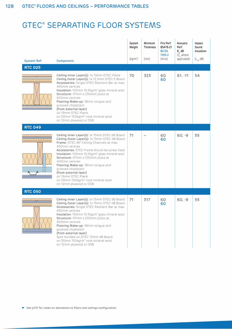
128 GTEC® FLOORS AND CEILINGS – PERFORMANCE TABLES
System Ref. Component
System
Weight
(kg/m2)
Minimum
Thickness
(mm)
Fire Perf.
BS476-21
BS EN
1365-2
(mins)
Acoustic
Perf.
Rw dB
(Ctr where
applicable)
Impact
Sound
Insulation
(Lnw
dB)
RTC 025
Ceiling Inner Layer(s): 1x 19mm GTEC Plank
Ceiling Outer Layer(s): 1x 12.5mm GTEC E Board
Accessories: Single GTEC Resilient Bar at max.
450mm centres
Insulation: 100mm 10.5kg/m3 glass mineral wool
Structure: 47mm x 200mm joists at
600mm centres
Flooring Make-up: 18mm tongue and
grooved chipboard
(from external layer)
on 19mm GTEC Plank
on 30mm 150kg/m3 rock mineral wool
on 12mm plywood or OSB
70 323 6060
61, -11 54
RTC 049
Ceiling Inner Layer(s): 1x 15mm GTEC dB Board
Ceiling Outer Layer(s): 1x 15mm GTEC dB Board
Frame: GTEC MF Ceiling Channels at max.
450mm centres
Accessories: GTEC Frame should be screw fixed
Insulation: 100mm 10.5kg/m3 glass mineral wool
Structure: 47mm x 200mm joists at
400mm centres
Flooring Make-up: 18mm tongue and
grooved chipboard
(from external layer)
on 19mm GTEC Plank
on 30mm 150kg/m3 rock mineral wool
on 12mm plywood or OSB
71 – 6060
60, -9 55
RTC 050
Ceiling Inner Layer(s): 1x 15mm GTEC dB Board
Ceiling Outer Layer(s): 1x 15mm GTEC dB Board
Accessories: Single GTEC Resilient Bar at max.
450mm centres
Insulation: 100mm 10.5kg/m3 glass mineral wool
Structure: 47mm x 200mm joists at
400mm centres
Flooring Make-up: 18mm tongue and
grooved chipboard
(from external layer)
Spot bonded on GTEC 15mm dB Board
on 30mm 150kg/m3 rock mineral wool
on 12mm plywood or OSB
71 317 6060
60, -9 55
GTEC® SEPARATING FLOOR SYSTEMS
See p137 for notes on alterations to floors and ceilings configuration.
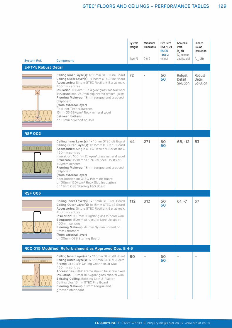
129GTEC® FLOORS AND CEILINGS – PERFORMANCE TABLES
ENQUIRYLINE T: 01275 377789 E: [email protected] www.siniat.co.uk
System Ref. Component
System
Weight
(kg/m2)
Minimum
Thickness
(mm)
Fire Perf.
BS476-21
BS EN
1365-2
(mins)
Acoustic
Perf.
Rw dB
(Ctr where
applicable)
Impact
Sound
Insulation
(Lnw
dB)
E-FT-1: Robust Detail
Ceiling Inner Layer(s): 1x 15mm GTEC Fire Board
Ceiling Outer Layer(s): 1x 15mm GTEC Fire Board
Accessories: Single GTEC Resilient Bar at max.
450mm centres
Insulation: 100mm 10-33kg/m3 glass mineral wool
Structure: min. 240mm engineered timber I-joists
Flooring Make-up: 18mm tongue and grooved
chipboard
(from external layer)
Resilient Timber battens
13mm 33-36kg/m3 Rock mineral wool
between battens
on 15mm plywood or OSB
72 - 6060
Robust Detail Solution
Robust Detail Solution
RSF 002
Ceiling Inner Layer(s): 1x 15mm GTEC dB Board
Ceiling Outer Layer(s): 1x 15mm GTEC dB Board
Accessories: Single GTEC Resilient Bar at max.
450mm centres
Insulation: 100mm 23kg/m3 glass mineral wool
Structure: 150mm Structural Steel Joists at
400mm centres
Flooring Make-up: 18mm tongue and grooved
chipboard
(from external layer)
Spot bonded on GTEC 15mm dB Board
on 30mm 120kg/m3 Rock Slab Insulation
on 11mm OSB Sterling T&G Board
44 271 6060
65, -12 53
RSF 003
Ceiling Inner Layer(s): 1x 15mm GTEC dB Board
Ceiling Outer Layer(s): 1x 15mm GTEC dB Board
Accessories: Single GTEC Resilient Bar at max.
450mm centres
Insulation: 100mm 10kg/m3 glass mineral wool
Structure: 150mm Structural Steel Joists at
400mm centres
Flooring Make-up: 40mm Gyvlon Screed on
6mm Ethafoam
(from external layer)
on 20mm OSB Sterling Board
112 313 6060
61, -7 57
RCC 015 Modified: Refurbishment as Approved Doc. E 4-3
Ceiling Inner Layer(s): 1x 12.5mm GTEC dB Board
Ceiling Outer Layer(s): 1x 12.5mm GTEC dB Board
Frame: GTEC MF Ceiling Channels at Max
450mm centres
Accessories: GTEC Frame should be screw fixed
Insulation: 100mm 10.5kg/m3 glass mineral wool
Existing Ceiling: Existing Lath & Plaster
Ceiling plus 15mm GTEC Fire Board
Flooring Make-up: 18mm tongue and
grooved chipboard
80 – 6060
– –
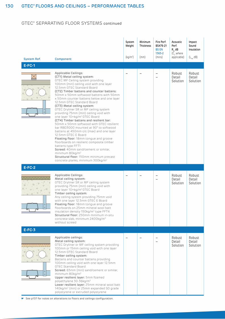
130 GTEC® FLOORS AND CEILINGS – PERFORMANCE TABLES
System Ref. Component
System
Weight
(kg/m2)
Minimum
Thickness
(mm)
Fire Perf.
BS476-21
BS EN
1365-2
(mins)
Acoustic
Perf.
Rw dB
(Ctr where
applicable)
Impact
Sound
Insulation
(Lnw
dB)
E-FC-1
Applicable Ceilings:
(CT1) Metal ceiling system:
GTEC MF Ceiling system providing
100mm (min) ceiling void with one layer
12.5mm GTEC Standard Board
(CT2) Timber battens and counter battens:
50mm x 50mm softwood battens with 50mm
x 50mm counter battens below and one layer
12.5mm GTEC Standard Board
(CT3) Metal ceiling system:
GTEC Dryliner SR or MF ceiling system
providing 75mm (min) ceiling void with
one layer 10+kg/m2 GTEC Board
(CT4) Timber battens and resilient bar:
50mm x 50mm softwood with GTEC resilient
bar RBD3000 mounted at 90° to softwood
battens at 450mm c/c (max) and one layer
12.5mm GTEC E Board
Floating floor: 18mm tongue and groove
floorboards on resilient composite timber
battens type FFT1
Screed: 40mm sand/cement or similar,
minimum 80kg/m2
Structural floor: 150mm minimum precast
concrete planks, minimum 300kg/m2
– – ––
Robust Detail Solution
Robust Detail Solution
E-FC-2
Applicable Ceilings:
Metal ceiling system:
GTEC Dryliner SR or MF ceiling system
providing 75mm (min) ceiling void with
one layer 10+kg/m2 GTEC Board
Timber ceiling system:
Any ceiling system providing 75mm void
with one layer 12.5mm GTEC E Board
Floating floor: 18mm tongue and groove
floorboards on 25mm mineral wool batt
insulation density 150kg/m3 type FFT4
Structural floor: 250mm minimum in-situ
concrete slab, minimum 2400kg/m3
without screed
– – ––
Robust Detail Solution
Robust Detail Solution
E-FC-3
Applicable ceilings:
Metal ceiling system:
GTEC Dryliner or MF ceiling system providing
100mm or 15mm ceiling void with one layer
12.5mm GTEC Standard Board
Timber ceiling system:
Battens and counter battens providing
100mm ceiling void with one layer 12.5mm
GTEC Standard Board
Screed: 65mm (min) sand/cement or similar,
minimum 80kg/m2
Upper resilient layer: 5mm foamed
polyethylene 30-36kg/m3
Lower resilient layer: 25mm mineral wool batt
140kg/m3 (min) or 25mm expanded SD grade
polystyrene or extruded polystyrene
– – ––
Robust Detail Solution
Robust Detail Solution
GTEC® SEPARATING FLOOR SYSTEMS continued
See p137 for notes on alterations to floors and ceilings configuration.
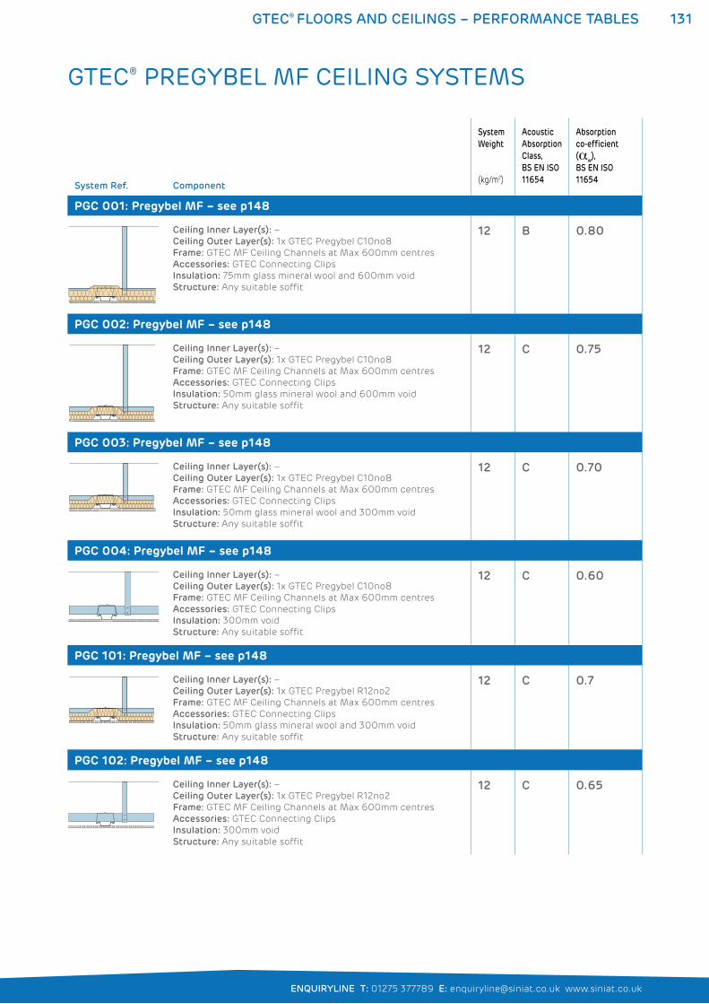
131GTEC® FLOORS AND CEILINGS – PERFORMANCE TABLES
ENQUIRYLINE T: 01275 377789 E: [email protected] www.siniat.co.uk
System Ref. Component
System
Weight
(kg/m2)
Acoustic
Absorption
Class,
BS EN ISO
11654
Absorption
co-efficient
(�w),
BS EN ISO
11654
PGC 001: Pregybel MF – see p148
Ceiling Inner Layer(s): –
Ceiling Outer Layer(s): 1x GTEC Pregybel C10no8
Frame: GTEC MF Ceiling Channels at Max 600mm centres
Accessories: GTEC Connecting Clips
Insulation: 75mm glass mineral wool and 600mm void
Structure: Any suitable soffit
12 B 0.80
PGC 002: Pregybel MF – see p148
Ceiling Inner Layer(s): –
Ceiling Outer Layer(s): 1x GTEC Pregybel C10no8
Frame: GTEC MF Ceiling Channels at Max 600mm centres
Accessories: GTEC Connecting Clips
Insulation: 50mm glass mineral wool and 600mm void
Structure: Any suitable soffit
12 C 0.75
PGC 003: Pregybel MF – see p148
Ceiling Inner Layer(s): –
Ceiling Outer Layer(s): 1x GTEC Pregybel C10no8
Frame: GTEC MF Ceiling Channels at Max 600mm centres
Accessories: GTEC Connecting Clips
Insulation: 50mm glass mineral wool and 300mm void
Structure: Any suitable soffit
12 C 0.70
PGC 004: Pregybel MF – see p148
Ceiling Inner Layer(s): –
Ceiling Outer Layer(s): 1x GTEC Pregybel C10no8
Frame: GTEC MF Ceiling Channels at Max 600mm centres
Accessories: GTEC Connecting Clips
Insulation: 300mm void
Structure: Any suitable soffit
12 C 0.60
PGC 101: Pregybel MF – see p148
Ceiling Inner Layer(s): –
Ceiling Outer Layer(s): 1x GTEC Pregybel R12no2
Frame: GTEC MF Ceiling Channels at Max 600mm centres
Accessories: GTEC Connecting Clips
Insulation: 50mm glass mineral wool and 300mm void
Structure: Any suitable soffit
12 C 0.7
PGC 102: Pregybel MF – see p148
Ceiling Inner Layer(s): –
Ceiling Outer Layer(s): 1x GTEC Pregybel R12no2
Frame: GTEC MF Ceiling Channels at Max 600mm centres
Accessories: GTEC Connecting Clips
Insulation: 300mm void
Structure: Any suitable soffit
12 C 0.65
GTEC® PREGYBEL MF CEILING SYSTEMS
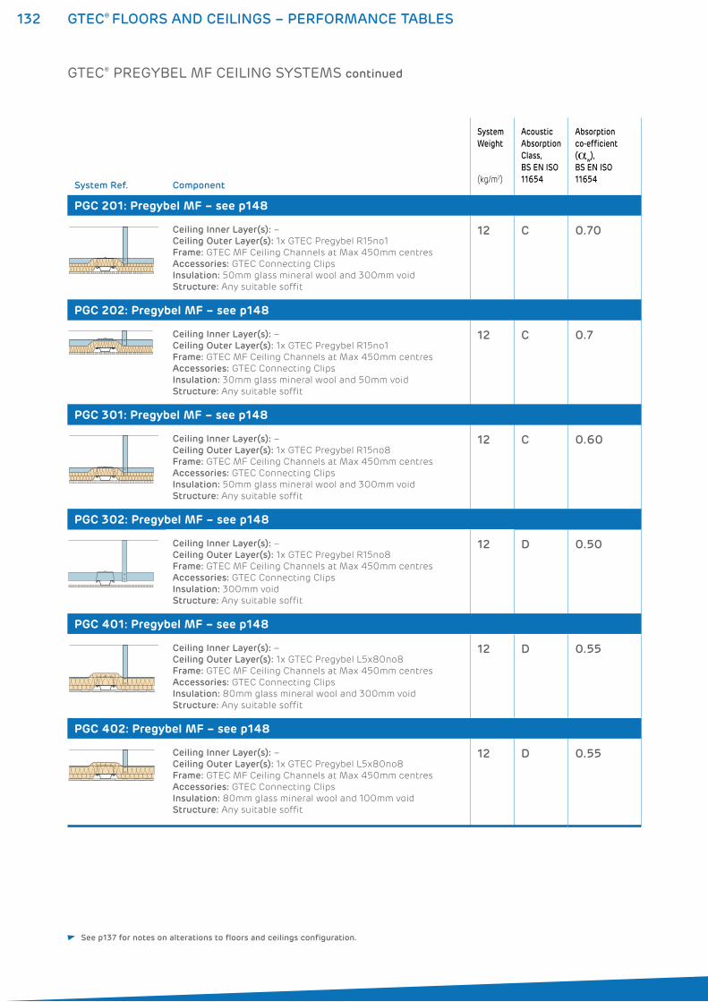
132 GTEC® FLOORS AND CEILINGS – PERFORMANCE TABLES
System Ref. Component
System
Weight
(kg/m2)
Acoustic
Absorption
Class,
BS EN ISO
11654
Absorption
co-efficient
(�w),
BS EN ISO
11654
PGC 201: Pregybel MF – see p148
Ceiling Inner Layer(s): –
Ceiling Outer Layer(s): 1x GTEC Pregybel R15no1
Frame: GTEC MF Ceiling Channels at Max 450mm centres
Accessories: GTEC Connecting Clips
Insulation: 50mm glass mineral wool and 300mm void
Structure: Any suitable soffit
12 C 0.70
PGC 202: Pregybel MF – see p148
Ceiling Inner Layer(s): –
Ceiling Outer Layer(s): 1x GTEC Pregybel R15no1
Frame: GTEC MF Ceiling Channels at Max 450mm centres
Accessories: GTEC Connecting Clips
Insulation: 30mm glass mineral wool and 50mm void
Structure: Any suitable soffit
12 C 0.7
PGC 301: Pregybel MF – see p148
Ceiling Inner Layer(s): –
Ceiling Outer Layer(s): 1x GTEC Pregybel R15no8
Frame: GTEC MF Ceiling Channels at Max 450mm centres
Accessories: GTEC Connecting Clips
Insulation: 50mm glass mineral wool and 300mm void
Structure: Any suitable soffit
12 C 0.60
PGC 302: Pregybel MF – see p148
Ceiling Inner Layer(s): –
Ceiling Outer Layer(s): 1x GTEC Pregybel R15no8
Frame: GTEC MF Ceiling Channels at Max 450mm centres
Accessories: GTEC Connecting Clips
Insulation: 300mm void
Structure: Any suitable soffit
12 D 0.50
PGC 401: Pregybel MF – see p148
Ceiling Inner Layer(s): –
Ceiling Outer Layer(s): 1x GTEC Pregybel L5x80no8
Frame: GTEC MF Ceiling Channels at Max 450mm centres
Accessories: GTEC Connecting Clips
Insulation: 80mm glass mineral wool and 300mm void
Structure: Any suitable soffit
12 D 0.55
PGC 402: Pregybel MF – see p148
Ceiling Inner Layer(s): –
Ceiling Outer Layer(s): 1x GTEC Pregybel L5x80no8
Frame: GTEC MF Ceiling Channels at Max 450mm centres
Accessories: GTEC Connecting Clips
Insulation: 80mm glass mineral wool and 100mm void
Structure: Any suitable soffit
12 D 0.55
GTEC® PREGYBEL MF CEILING SYSTEMS continued
See p137 for notes on alterations to floors and ceilings configuration.
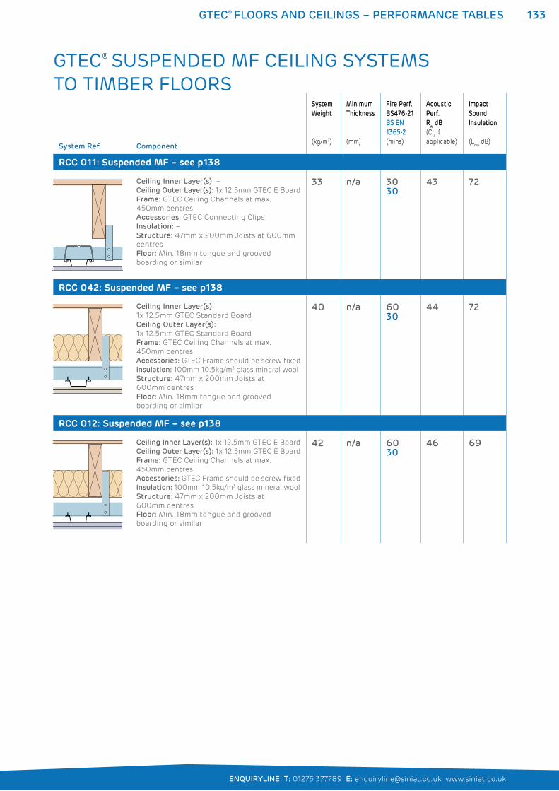
133GTEC® FLOORS AND CEILINGS – PERFORMANCE TABLES
ENQUIRYLINE T: 01275 377789 E: [email protected] www.siniat.co.uk
GTEC® SUSPENDED MF CEILING SYSTEMS TO TIMBER FLOORS
System Ref. Component
System
Weight
(kg/m2)
Minimum
Thickness
(mm)
Fire Perf.
BS476-21
BS EN
1365-2
(mins)
Acoustic
Perf.
Rw dB
(Ctr if
applicable)
Impact
Sound
Insulation
(Lnw
dB)
RCC 011: Suspended MF – see p138
Ceiling Inner Layer(s): –
Ceiling Outer Layer(s): 1x 12.5mm GTEC E Board
Frame: GTEC Ceiling Channels at max.
450mm centres
Accessories: GTEC Connecting Clips
Insulation: –
Structure: 47mm x 200mm Joists at 600mm
centres
Floor: Min. 18mm tongue and grooved
boarding or similar
33 n/a 3030
43 72
RCC 042: Suspended MF – see p138
Ceiling Inner Layer(s):
1x 12.5mm GTEC Standard Board
Ceiling Outer Layer(s):
1x 12.5mm GTEC Standard Board
Frame: GTEC Ceiling Channels at max.
450mm centres
Accessories: GTEC Frame should be screw fixed
Insulation: 100mm 10.5kg/m3 glass mineral wool
Structure: 47mm x 200mm Joists at
600mm centres
Floor: Min. 18mm tongue and grooved
boarding or similar
40 n/a 6030
44 72
RCC 012: Suspended MF – see p138
Ceiling Inner Layer(s): 1x 12.5mm GTEC E Board
Ceiling Outer Layer(s): 1x 12.5mm GTEC E Board
Frame: GTEC Ceiling Channels at max.
450mm centres
Accessories: GTEC Frame should be screw fixed
Insulation: 100mm 10.5kg/m3 glass mineral wool
Structure: 47mm x 200mm Joists at
600mm centres
Floor: Min. 18mm tongue and grooved
boarding or similar
42 n/a 6030
46 69
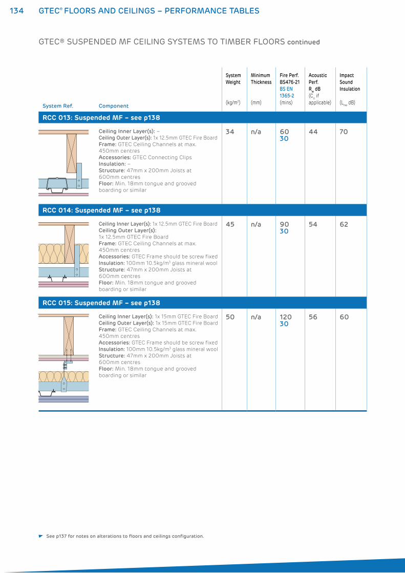
134 GTEC® FLOORS AND CEILINGS – PERFORMANCE TABLES
System Ref. Component
System
Weight
(kg/m2)
Minimum
Thickness
(mm)
Fire Perf.
BS476-21
BS EN
1365-2
(mins)
Acoustic
Perf.
Rw dB
(Ctr if
applicable)
Impact
Sound
Insulation
(Lnw
dB)
RCC 013: Suspended MF – see p138
Ceiling Inner Layer(s): –
Ceiling Outer Layer(s): 1x 12.5mm GTEC Fire Board
Frame: GTEC Ceiling Channels at max.
450mm centres
Accessories: GTEC Connecting Clips
Insulation: –
Structure: 47mm x 200mm Joists at
600mm centres
Floor: Min. 18mm tongue and grooved
boarding or similar
34 n/a 6030
44 70
RCC 014: Suspended MF – see p138
Ceiling Inner Layer(s): 1x 12.5mm GTEC Fire Board
Ceiling Outer Layer(s):
1x 12.5mm GTEC Fire Board
Frame: GTEC Ceiling Channels at max.
450mm centres
Accessories: GTEC Frame should be screw fixed
Insulation: 100mm 10.5kg/m3 glass mineral wool
Structure: 47mm x 200mm Joists at
600mm centres
Floor: Min. 18mm tongue and grooved
boarding or similar
45 n/a 9030
54 62
RCC 015: Suspended MF – see p138
Ceiling Inner Layer(s): 1x 15mm GTEC Fire Board
Ceiling Outer Layer(s): 1x 15mm GTEC Fire Board
Frame: GTEC Ceiling Channels at max.
450mm centres
Accessories: GTEC Frame should be screw fixed
Insulation: 100mm 10.5kg/m3 glass mineral wool
Structure: 47mm x 200mm Joists at
600mm centres
Floor: Min. 18mm tongue and grooved
boarding or similar
50 n/a 12030
56 60
See p137 for notes on alterations to floors and ceilings configuration.
GTEC® SUSPENDED MF CEILING SYSTEMS TO TIMBER FLOORS continued
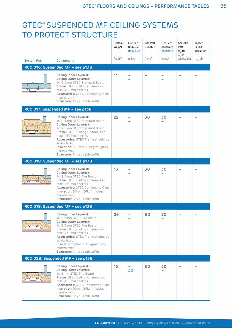
135GTEC® FLOORS AND CEILINGS – PERFORMANCE TABLES
ENQUIRYLINE T: 01275 377789 E: [email protected] www.siniat.co.uk
GTEC® SUSPENDED MF CEILING SYSTEMS TO PROTECT STRUCTURE
System Ref. Component
System
Weight
(kg/m2)
Fire Perf.
BS476-21
BS476-22
(mins)
Fire Perf.
BS476-23
(mins)
Fire Perf.
BS1364-2
BS1365-2
(mins)
Acoustic
Perf.
Rw dB
(Ctr if
applicable)
Impact
Sound
Insulation
(Lnw
dB)
RCC 016: Suspended MF – see p138
Ceiling Inner Layer(s): –
Ceiling Outer Layer(s):
1x 12.5mm GTEC Standard Board
Frame: GTEC Ceiling Channels at
max. 450mm centres
Accessories: GTEC Connecting Clips
Insulation: –
Structure: Any suitable soffit
11 ––
– ––
– –
RCC 017: Suspended MF – see p138
Ceiling Inner Layer(s):
1x 12.5mm GTEC Standard Board
Ceiling Outer Layer(s):
1x 12.5mm GTEC Standard Board
Frame: GTEC Ceiling Channels at
max. 450mm centres
Accessories: GTEC Frame should be
screw fixed
Insulation: 100mm 10.5kg/m3 glass
mineral wool
Structure: Any suitable soffit
22 ––
30 30–
– –
RCC 018: Suspended MF – see p138
Ceiling Inner Layer(s): –
Ceiling Outer Layer(s):
1x 12.5mm GTEC Fire Board
Frame: GTEC Ceiling Channels at
max. 450mm centres
Accessories: GTEC Connecting Clips
Insulation: 50mm 24kg/m3 glass
mineral wool
Structure: Any suitable soffit
13 ––
30 30–
– –
RCC 019: Suspended MF – see p138
Ceiling Inner Layer(s):
1x 12.5mm GTEC Fire Board
Ceiling Outer Layer(s):
1x 12.5mm GTEC Fire Board
Frame: GTEC Ceiling Channels at
max. 450mm centres
Accessories: GTEC Frame should be
screw fixed
Insulation: 50mm 10.5kg/m3 glass
mineral wool
Structure: Any suitable soffit
26 ––
60 30–
– –
RCC 028: Suspended MF – see p138
Ceiling Inner Layer(s): –
Ceiling Outer Layer(s):
1x 15mm GTEC Fire Board
Frame: GTEC Ceiling Channels at
max. 450mm centres
Accessories: GTEC Connecting Clips
Insulation: 50mm 24kg/m3 glass
mineral wool
Structure: Any suitable soffit
15 –30
60 30–
– –
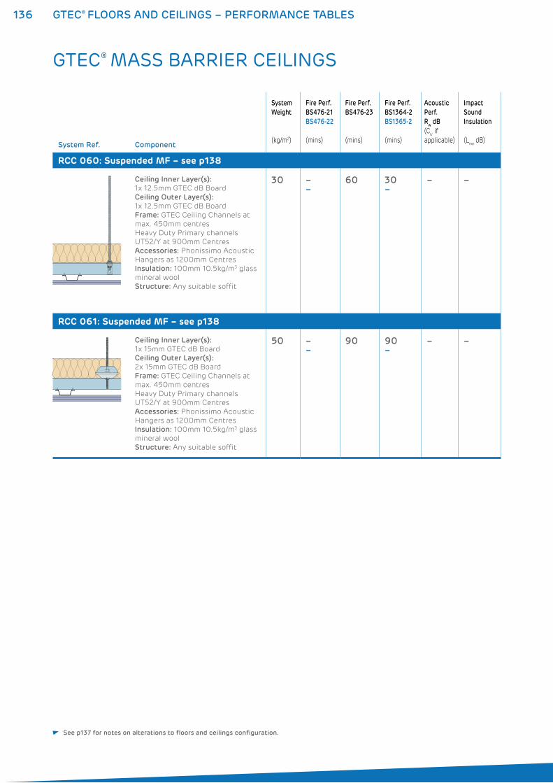
136 GTEC® FLOORS AND CEILINGS – PERFORMANCE TABLES
GTEC® MASS BARRIER CEILINGS
System Ref. Component
System
Weight
(kg/m2)
Fire Perf.
BS476-21
BS476-22
(mins)
Fire Perf.
BS476-23
(mins)
Fire Perf.
BS1364-2
BS1365-2
(mins)
Acoustic
Perf.
Rw dB
(Ctr if
applicable)
Impact
Sound
Insulation
(Lnw
dB)
RCC 060: Suspended MF – see p138
Ceiling Inner Layer(s):
1x 12.5mm GTEC dB Board
Ceiling Outer Layer(s):
1x 12.5mm GTEC dB Board
Frame: GTEC Ceiling Channels at
max. 450mm centres
Heavy Duty Primary channels
UT52/Y at 900mm Centres
Accessories: Phonissimo Acoustic
Hangers as 1200mm Centres
Insulation: 100mm 10.5kg/m3 glass
mineral wool
Structure: Any suitable soffit
30 ––
60 30–
– –
RCC 061: Suspended MF – see p138
Ceiling Inner Layer(s):
1x 15mm GTEC dB Board
Ceiling Outer Layer(s):
2x 15mm GTEC dB Board
Frame: GTEC Ceiling Channels at
max. 450mm centres
Heavy Duty Primary channels
UT52/Y at 900mm Centres
Accessories: Phonissimo Acoustic
Hangers as 1200mm Centres
Insulation: 100mm 10.5kg/m3 glass
mineral wool
Structure: Any suitable soffit
50 ––
90 90–
– –
See p137 for notes on alterations to floors and ceilings configuration.
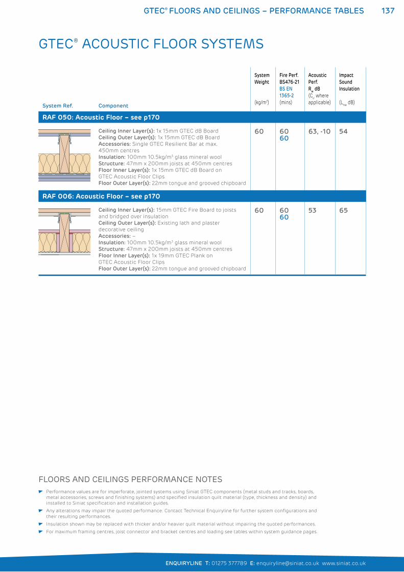
137GTEC® FLOORS AND CEILINGS – PERFORMANCE TABLES
ENQUIRYLINE T: 01275 377789 E: [email protected] www.siniat.co.uk
FLOORS AND CEILINGS PERFORMANCE NOTES Performance values are for imperforate, jointed systems using Siniat GTEC components (metal studs and tracks, boards,
metal accessories, screws and finishing systems) and specified insulation quilt material (type, thickness and density) and
installed to Siniat specification and installation guides.
Any alterations may impair the quoted performance. Contact Technical Enquiryline for further system configurations and
their resulting performances.
Insulation shown may be replaced with thicker and/or heavier quilt material without impairing the quoted performances.
For maximum framing centres, joist connector and bracket centres and loading see tables within system guidance pages.
System Ref. Component
System
Weight
(kg/m2)
Fire Perf.
BS476-21
BS EN
1365-2
(mins)
Acoustic
Perf.
Rw dB
(Ctr where
applicable)
Impact
Sound
Insulation
(Lnw
dB)
RAF 050: Acoustic Floor – see p170
Ceiling Inner Layer(s): 1x 15mm GTEC dB Board
Ceiling Outer Layer(s): 1x 15mm GTEC dB Board
Accessories: Single GTEC Resilient Bar at max.
450mm centres
Insulation: 100mm 10.5kg/m3 glass mineral wool
Structure: 47mm x 200mm joists at 450mm centres
Floor Inner Layer(s): 1x 15mm GTEC dB Board on
GTEC Acoustic Floor Clips
Floor Outer Layer(s): 22mm tongue and grooved chipboard
60 6060
63, -10 54
RAF 006: Acoustic Floor – see p170
Ceiling Inner Layer(s): 15mm GTEC Fire Board to joists
and bridged over insulation
Ceiling Outer Layer(s): Existing lath and plaster
decorative ceiling
Accessories: –
Insulation: 100mm 10.5kg/m3 glass mineral wool
Structure: 47mm x 200mm joists at 450mm centres
Floor Inner Layer(s): 1x 19mm GTEC Plank on
GTEC Acoustic Floor Clips
Floor Outer Layer(s): 22mm tongue and grooved chipboard
60 6060
53 65
GTEC® ACOUSTIC FLOOR SYSTEMS
138 GTEC® SUSPENDED MF CEILING
GTEC® SUSPENDED MF CEILING SYSTEMSThe GTEC Suspended MF Ceilings are used to create ‘false ceilings’
which house services between the ceiling and soffit. The large voids
created also improve acoustic, fire and thermal performance.
GTEC Suspended MF Ceilings are formed from a series of GTEC
Primary Channels hung from the soffit. Attached to these channels
are GTEC Ceiling Channels, slotted into GTEC Edge Channel to form
the frame. GTEC Board is fixed to the MF frame to complete the
system. Refer to the System Performance Tables on pages 133 to 136
for full details.
WHERE TO USE: GTEC Suspended MF Ceilings are used for commercial
applications where services are required below the soffit.
For ceilings with enhanced fire and acoustic performance
in commercial and residential applications.
FEATURES BENEFITS
Variable cavity depth Optimisable cavity size for service and
insulation requirements
High acoustic, fire and thermal capabilities Required performance levels are easily achieved
Creates a ‘false ceiling’ Can be used to upgrade or protect
existing structures
Demountable Easy to renovate
Flat finish Provides a smooth surface for decorating
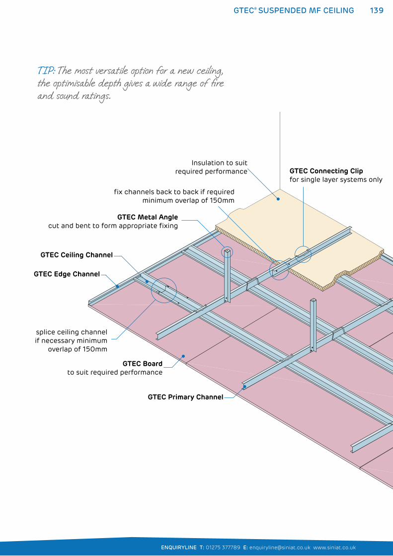
139
ENQUIRYLINE T: 01275 377789 E: [email protected] www.siniat.co.uk
GTEC® SUSPENDED MF CEILING
GTEC Metal Angle cut and bent to form appropriate fixing
GTEC Ceiling Channel
GTEC Edge Channel
GTEC Connecting Clip for single layer systems only
fix channels back to back if required minimum overlap of 150mm
splice ceiling channelif necessary minimum
overlap of 150mm
Insulation to suitrequired performance
GTEC Primary Channel
GTEC Boardto suit required performance
TIP: The most versatile option for a new ceiling, the optimisable depth gives a wide range of fire and sound ratings.
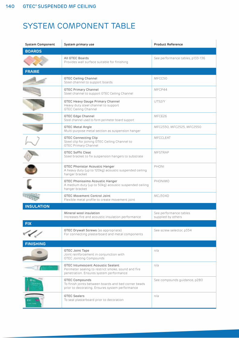
140 GTEC® SUSPENDED MF CEILING
SYSTEM COMPONENT TABLE
System Component System primary use Product Reference
BOARDS
All GTEC Boards
Provides wall surface suitable for finishing
See performance tables, p133-136
FRAME
GTEC Ceiling Channel
Steel channel to support boards
MFCC50
GTEC Primary Channel
Steel channel to support GTEC Ceiling Channel
MFCP44
GTEC Heavy Gauge Primary Channel
Heavy duty steel channel to support
GTEC Ceiling Channel
UT52/Y
GTEC Edge Channel
Steel channel used to form perimeter board support
MFCE26
GTEC Metal Angle
Multi-purpose metal section as suspension hanger
MFC2330, MFC2525, MFC2550
GTEC Connecting Clip
Steel clip for joining GTEC Ceiling Channel to
GTEC Primary Channel
MFCCLEAT
GTEC Soffit Cleat
Steel bracket to fix suspension hangers to substrate
MFSTRAP
GTEC Phonistar Acoustic Hanger
A heavy duty (up to 120kg) acoustic suspended ceiling
hanger bracket
PHONI
GTEC Phonissimo Acoustic Hanger
A medium duty (up to 50kg) acoustic suspended ceiling
hanger bracket
PHONIMO
GTEC Movement Control Joint
Flexible metal profile to create movement joint
MCJ304D
INSULATION
Mineral wool insulation
Increases fire and acoustic insulation performance
See performance tables
supplied by others
FIX
GTEC Drywall Screws (as appropriate)
For connecting plasterboard and metal components
See screw selector, p334
FINISHING
GTEC Joint Tape
Joint reinforcement in conjunction with
GTEC Jointing Compounds
n/a
GTEC Intumescent Acoustic Sealant
Perimeter sealing to restrict smoke, sound and fire
penetration. Ensures system performance
n/a
GTEC Compounds
To finish joints between boards and bed corner beads
prior to decorating. Ensures system performance
See compounds guidance, p280
GTEC Sealers
To seal plasterboard prior to decoration
n/a
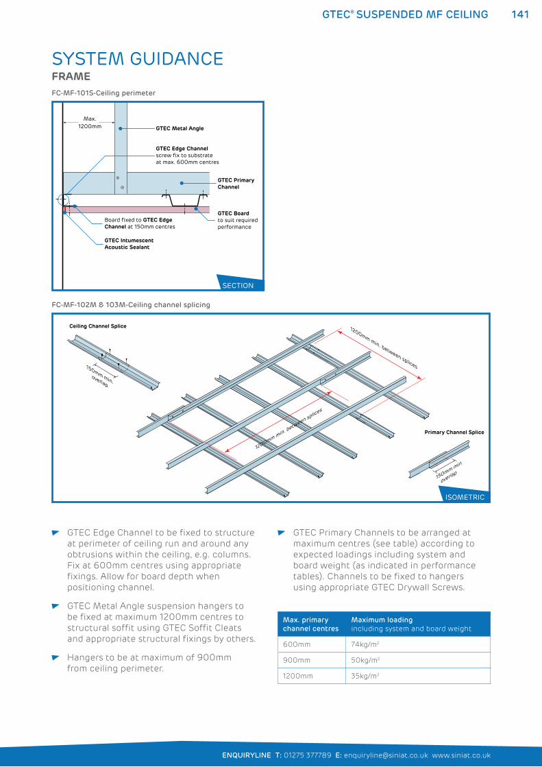
141
ENQUIRYLINE T: 01275 377789 E: [email protected] www.siniat.co.uk
GTEC® SUSPENDED MF CEILING
GTEC Edge Channel to be fixed to structure
at perimeter of ceiling run and around any
obtrusions within the ceiling, e.g. columns.
Fix at 600mm centres using appropriate
fixings. Allow for board depth when
positioning channel.
GTEC Metal Angle suspension hangers to
be fixed at maximum 1200mm centres to
structural soffit using GTEC Soffit Cleats
and appropriate structural fixings by others.
Hangers to be at maximum of 900mm
from ceiling perimeter.
GTEC Primary Channels to be arranged at
maximum centres (see table) according to
expected loadings including system and
board weight (as indicated in performance
tables). Channels to be fixed to hangers
using appropriate GTEC Drywall Screws.
Max. primary
channel centres
Maximum loading
including system and board weight
600mm 74kg/m2
900mm 50kg/m2
1200mm 35kg/m2
SYSTEM GUIDANCEFRAME
GTEC Intumescent Acoustic Sealant
GTEC Edge Channelscrew fix to substrateat max. 600mm centres
GTEC Primary Channel
GTEC Metal Angle
GTEC Boardto suit required performance
Board fixed to GTEC Edge Channel at 150mm centres
Max.1200mm
FC-MF-101S-Ceiling perimeter
150mm min
overlap
1200mm min. between splices
150mm min.overlap
1200mm min. between splices
Ceiling Channel Splice
Primary Channel Splice
FC-MF-102M & 103M-Ceiling channel splicing
SECTION
ISOMETRIC
142 GTEC® SUSPENDED MF CEILING
FRAME continued
INSULATION
GTEC Ceiling Channels to be located into
GTEC Edge Channel at maximum. 450mm
centres and fixed at right angles to GTEC
Primary Channel.
Fixing between Ceiling and Primary channels
to be made using appropriate GTEC Drywall
Screws.
GTEC Connecting Clips may only be used to
connect GTEC Ceiling Channel to Primary
Channel in single board layer systems with
no additional loadings. GTEC Connecting
Clips to be alternated in direction to
counteract any movement.
GTEC Primary Channels may be spliced
if necessary by fixing back-to-back with
minimum four appropriate GTEC Drywall
Screws.
GTEC Ceiling Channels may be jointed by
overlapping profiles by minimum 150mm
and fixing with minimum four appropriate
GTEC Drywall Screws.
Any insulation to be of type and thickness
to achieve performance and installed in a
continuous layer between primary channels
and over ceiling channels and boards.
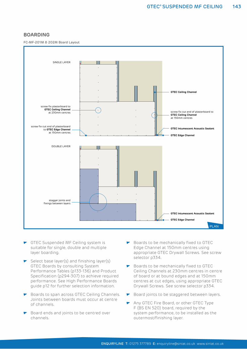
143
ENQUIRYLINE T: 01275 377789 E: [email protected] www.siniat.co.uk
GTEC® SUSPENDED MF CEILING
GTEC Suspended MF Ceiling system is
suitable for single, double and multiple
layer boarding.
Select base layer(s) and finishing layer(s)
GTEC Boards by consulting System
Performance Tables (p133-136) and Product
Specification (p294-307) to achieve required
performance. See High Performance Boards
guide p12 for further selection information.
Boards to span across GTEC Ceiling Channels.
Joints between boards must occur at centre
of channels.
Board ends and joints to be centred over
channels.
Boards to be mechanically fixed to GTEC
Edge Channel at 150mm centres using
appropriate GTEC Drywall Screws. See screw
selector p334.
Boards to be mechanically fixed to GTEC
Ceiling Channels at 230mm centres in centre
of board or at bound edges and at 150mm
centres at cut edges, using appropriate GTEC
Drywall Screws. See screw selector p334.
Board joints to be staggered between layers.
Any GTEC Fire Board, or other GTEC Type
F (BS EN 520) board, required by the
system performance, to be installed as the
outermost/finishing layer.
BOARDING
GTEC Edge Channel
GTEC Edge Channel
GTEC Intumescent Acoustic Sealant
GTEC Intumescent Acoustic Sealant
screw fix plasterboard to GTEC Ceiling Channel
at 230mm centres screw fix cut end of plasterboard to GTEC Ceiling Channel at 150mm centres
screw fix cut end of plasterboard to GTEC Edge Channel
at 150mm centres
GTEC Ceiling Channel
stagger joints and fixings between layers
SINGLE LAYER
DOUBLE LAYER
FC-MF-201M & 202M Board Layout
PLAN
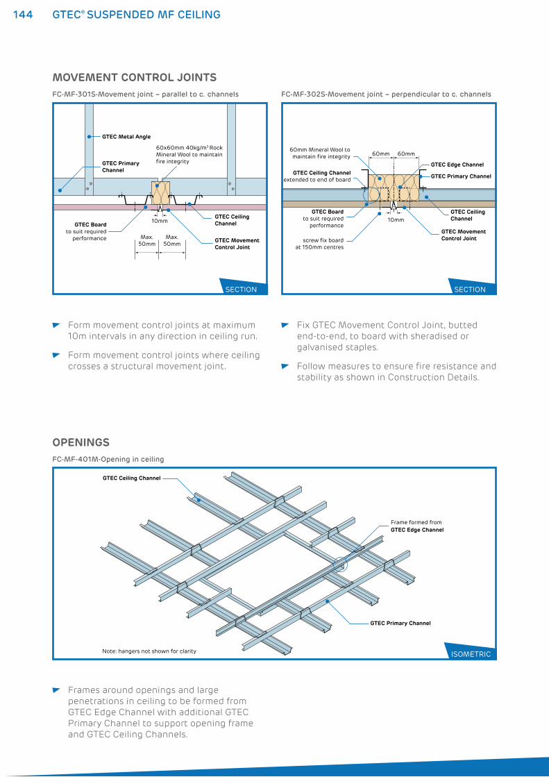
144 GTEC® SUSPENDED MF CEILING
MOVEMENT CONTROL JOINTS
GTEC Primary Channel
60x60mm 40kg/m3 Rock Mineral Wool to maintain fire integrity
GTEC Ceiling Channel
GTEC Metal Angle
GTEC Movement Control Joint
GTEC Boardto suit required
performance
10mm
Max. 50mm
Max. 50mm
FC-MF-301S-Movement joint – parallel to c. channels
GTEC Primary Channel
GTEC Edge Channel
screw fix boardat 150mm centres
60mm Mineral Wool tomaintain fire integrity
GTEC Ceiling Channel
GTEC Ceiling Channelextended to end of board
GTEC Boardto suit required
performance
60mm 60mm
10mm
GTEC Movement Control Joint
FC-MF-302S-Movement joint – perpendicular to c. channels
SECTION SECTION
Form movement control joints at maximum
10m intervals in any direction in ceiling run.
Form movement control joints where ceiling
crosses a structural movement joint.
Fix GTEC Movement Control Joint, butted
end-to-end, to board with sheradised or
galvanised staples.
Follow measures to ensure fire resistance and
stability as shown in Construction Details.
Frames around openings and large
penetrations in ceiling to be formed from
GTEC Edge Channel with additional GTEC
Primary Channel to support opening frame
and GTEC Ceiling Channels.
OPENINGS
Frame formed from GTEC Edge Channel
GTEC Primary Channel
GTEC Ceiling Channel
Note: hangers not shown for clarity
FC-MF-401M-Opening in ceiling
ISOMETRIC
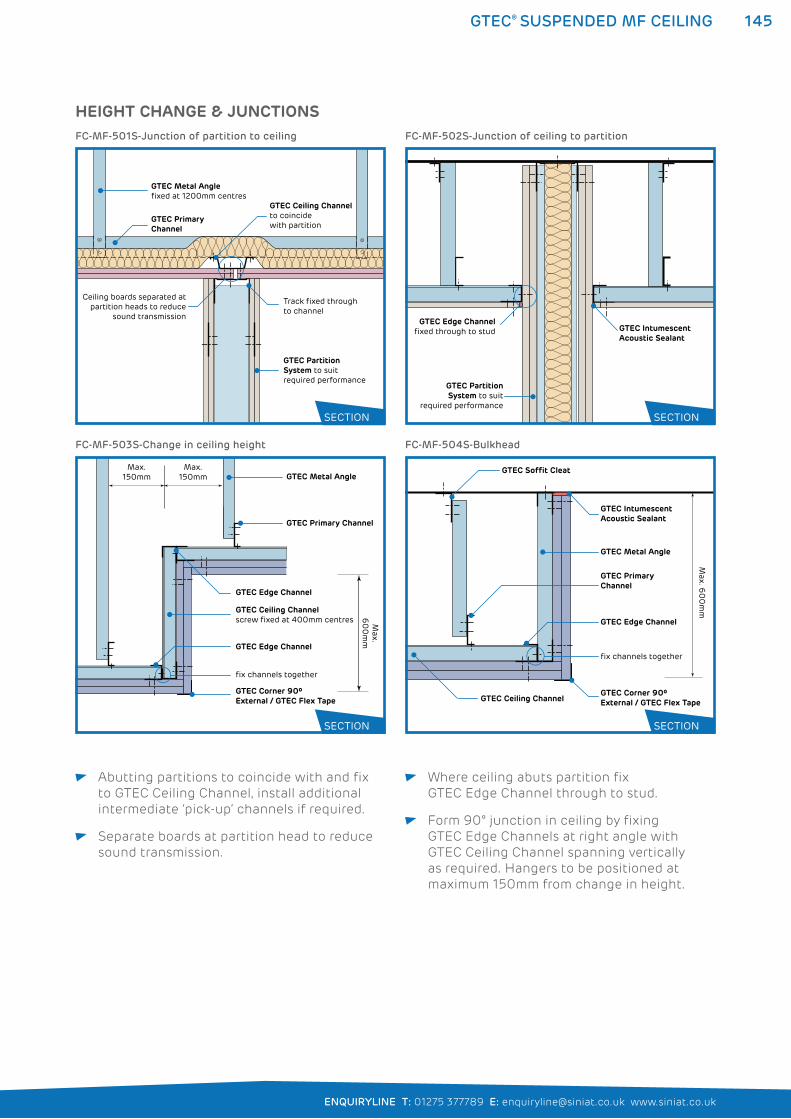
145
ENQUIRYLINE T: 01275 377789 E: [email protected] www.siniat.co.uk
GTEC® SUSPENDED MF CEILING
Abutting partitions to coincide with and fix
to GTEC Ceiling Channel, install additional
intermediate ‘pick-up’ channels if required.
Separate boards at partition head to reduce
sound transmission.
Where ceiling abuts partition fix
GTEC Edge Channel through to stud.
Form 90° junction in ceiling by fixing
GTEC Edge Channels at right angle with
GTEC Ceiling Channel spanning vertically
as required. Hangers to be positioned at
maximum 150mm from change in height.
GTEC Metal Angle
GTEC Primary Channel
GTEC Ceiling Channelscrew fixed at 400mm centres
GTEC Edge Channel
GTEC Edge Channel
GTEC Corner 90º External / GTEC Flex Tape
fix channels together
Max. 150mm
Max.
60
0m
m
Max. 150mm
GTEC Metal Angle
GTEC Primary Channel
GTEC Ceiling Channel
GTEC IntumescentAcoustic Sealant
GTEC Soffit Cleat
GTEC Edge Channel
GTEC Corner 90º External / GTEC Flex Tape
fix channels together
Max. 6
00
mm
FC-MF-503S-Change in ceiling height FC-MF-504S-Bulkhead
HEIGHT CHANGE & JUNCTIONS
GTEC Primary Channel
GTEC Ceiling Channelto coincide with partition
GTEC Metal Anglefixed at 1200mm centres
Ceiling boards separated atpartition heads to reduce
sound transmission
GTEC Partition System to suit required performance
Track fixed through to channel
FC-MF-501S-Junction of partition to ceiling
GTEC Edge Channelfixed through to stud GTEC Intumescent
Acoustic Sealant
GTEC PartitionSystem to suit
required performance
FC-MF-502S-Junction of ceiling to partition
SECTION
SECTION
SECTION
SECTION
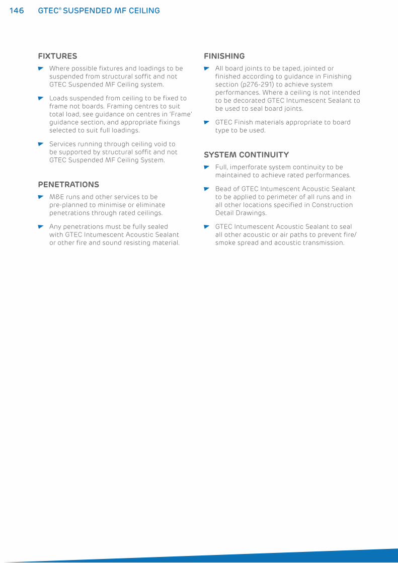
146 GTEC® SUSPENDED MF CEILING
FIXTURES Where possible fixtures and loadings to be
suspended from structural soffit and not
GTEC Suspended MF Ceiling system.
Loads suspended from ceiling to be fixed to
frame not boards. Framing centres to suit
total load, see guidance on centres in ‘Frame’
guidance section, and appropriate fixings
selected to suit full loadings.
Services running through ceiling void to
be supported by structural soffit and not
GTEC Suspended MF Ceiling System.SYSTEM CONTINUITY
Full, imperforate system continuity to be
maintained to achieve rated performances.
Bead of GTEC Intumescent Acoustic Sealant
to be applied to perimeter of all runs and in
all other locations specified in Construction
Detail Drawings.
GTEC Intumescent Acoustic Sealant to seal
all other acoustic or air paths to prevent fire/
smoke spread and acoustic transmission.
PENETRATIONS M&E runs and other services to be
pre-planned to minimise or eliminate
penetrations through rated ceilings.
Any penetrations must be fully sealed
with GTEC Intumescent Acoustic Sealant
or other fire and sound resisting material.
FINISHING All board joints to be taped, jointed or
finished according to guidance in Finishing
section (p276-291) to achieve system
performances. Where a ceiling is not intended
to be decorated GTEC Intumescent Sealant to
be used to seal board joints.
GTEC Finish materials appropriate to board
type to be used.
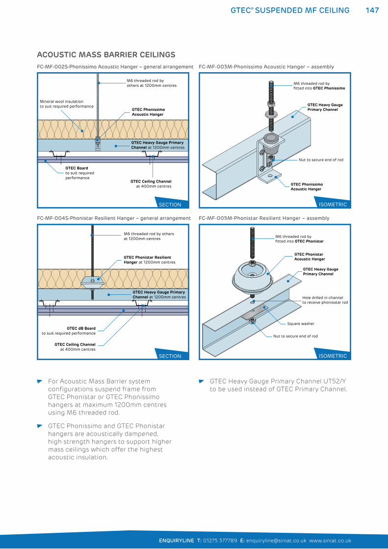
147
ENQUIRYLINE T: 01275 377789 E: [email protected] www.siniat.co.uk
GTEC® SUSPENDED MF CEILING
For Acoustic Mass Barrier system
configurations suspend frame from
GTEC Phonistar or GTEC Phonissimo
hangers at maximum 1200mm centres
using M6 threaded rod.
GTEC Phonissimo and GTEC Phonistar
hangers are acoustically dampened,
high strength hangers to support higher
mass ceilings which offer the highest
acoustic insulation.
GTEC Heavy Gauge Primary Channel UT52/Y
to be used instead of GTEC Primary Channel.
GTEC Ceiling Channelat 400mm centres
GTEC Phonistar Resilient Hanger at 1200mm centres
GTEC dB Boardto suit required performance
M6 threaded rod by othersat 1200mm centres
GTEC Heavy Gauge Primary Channel at 1200mm centres
M6 threaded rod by fitted into GTEC Phonistar
Nut to secure end of rod
Square washer
Hole drilled in channel to receive phoniostar rod
GTEC Heavy GaugePrimary Channel
GTEC Phonistar Acoustic Hanger
FC-MF-004S-Phonistar Resilient Hanger – general arrangement FC-MF-005M-Phonistar Resilient Hanger – assembly
ACOUSTIC MASS BARRIER CEILINGS
GTEC Ceiling Channelat 400mm centres
GTEC Phonissimo Acoustic Hanger
GTEC Heavy Gauge Primary Channel at 1200mm centres
GTEC Boardto suit requiredperformance
Mineral wool insulationto suit required performance
M6 threaded rod by others at 1200mm centres
FC-MF-002S-Phonissimo Acoustic Hanger – general arrangement
M6 threaded rod by fitted into GTEC Phonissimo
Nut to secure end of rod
GTEC Heavy GaugePrimary Channel
GTEC Phonissimo Acoustic Hanger
FC-MF-003M-Phonissimo Acoustic Hanger – assembly
SECTION
SECTION
ISOMETRIC
ISOMETRIC
148 GTEC® PREGYBEL MF CEILING
GTEC® PREGYBEL MF CEILING SYSTEMSThe GTEC Pregybel MF Ceiling system is used for creating sound
absorbing ceilings to control sound reflection in larger spaces,
creating a more comfortable level of sound and improved audibility.
GTEC Pregybel MF Ceilings combine the easy to install advantages of
the GTEC Suspended MF Ceiling with the sound absorption capability
of GTEC Pregybel Board. Using frame components from the GTEC
Suspended MF system enables flexible design and specification.
GTEC Pregybel board is perforated in a range of patterns for attractive
designs and reduction in the reflective surface of the board to limit
echo or reverberation. Refer to the System Performance Tables on
pages 131 to 132 for full performance details.
WHERE TO USE: GTEC Pregybel MF ceilings are used in commercial applications
where large, hard-surfaced and uninterrupted spaces would
otherwise suffer from echoing.
GTEC Pregybel MF ceilings are also required for corridors and
stairwells in residential blocks to reduce sound travel through
the building.
FEATURES BENEFITS
Variable cavity depth Cavity size can be optimised for service and
insulation requirements
Up to Class B acoustic absorption
Utilises GTEC Suspended MF framing One set of components on site
Easy to install
Creates a ‘false ceiling’ Can be used to upgrade existing structures
Perforated boards in a range of patterns Provides a range of aesthetic options to add
variation in large spaces
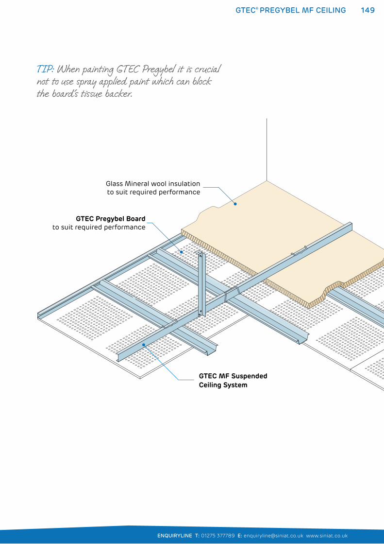
149
ENQUIRYLINE T: 01275 377789 E: [email protected] www.siniat.co.uk
GTEC® PREGYBEL MF CEILING
GTEC MF SuspendedCeiling System
GTEC Pregybel Boardto suit required performance
Glass Mineral wool insulationto suit required performance
TIP: When painting GTEC Pregybel it is crucial not to use spray applied paint which can block the board’s tissue backer.
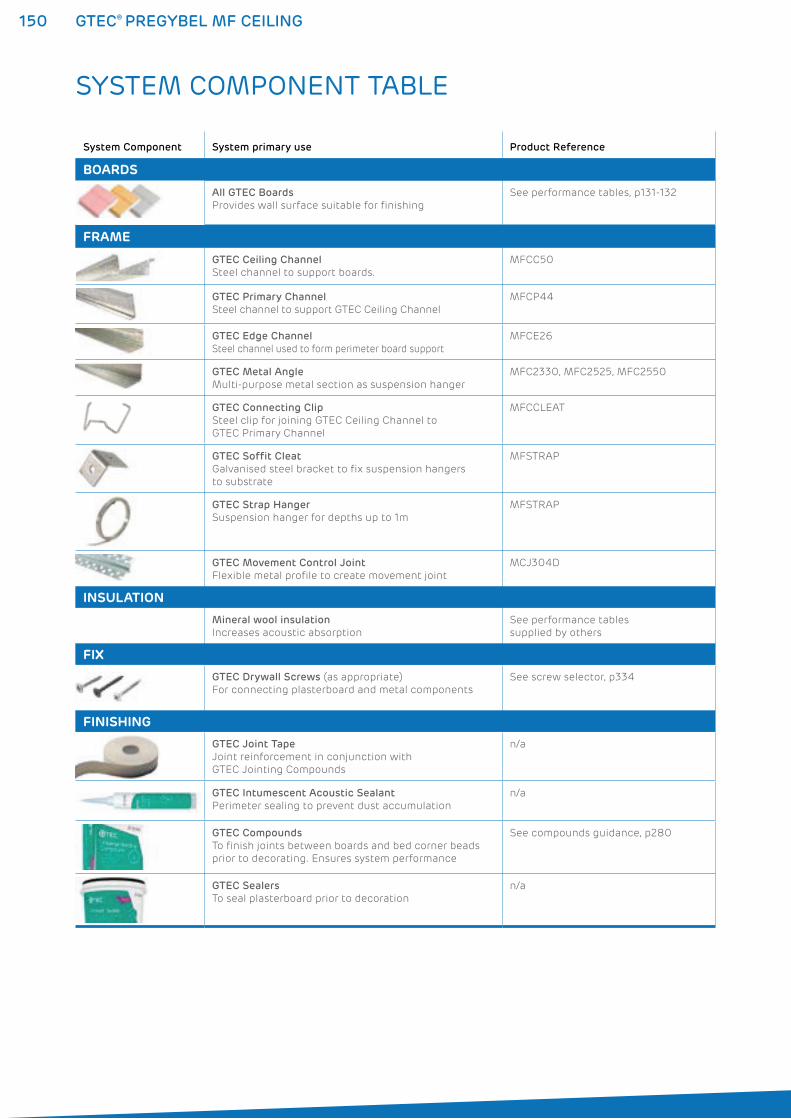
150 GTEC® PREGYBEL MF CEILING
SYSTEM COMPONENT TABLE
System Component System primary use Product Reference
BOARDS
All GTEC Boards
Provides wall surface suitable for finishing
See performance tables, p131-132
FRAME
GTEC Ceiling Channel
Steel channel to support boards.
MFCC50
GTEC Primary Channel
Steel channel to support GTEC Ceiling Channel
MFCP44
GTEC Edge Channel
Steel channel used to form perimeter board support
MFCE26
GTEC Metal Angle
Multi-purpose metal section as suspension hanger
MFC2330, MFC2525, MFC2550
GTEC Connecting Clip
Steel clip for joining GTEC Ceiling Channel to
GTEC Primary Channel
MFCCLEAT
GTEC Soffit Cleat
Galvanised steel bracket to fix suspension hangers
to substrate
MFSTRAP
GTEC Strap Hanger
Suspension hanger for depths up to 1m
MFSTRAP
GTEC Movement Control Joint
Flexible metal profile to create movement joint
MCJ304D
INSULATION
Mineral wool insulation
Increases acoustic absorption
See performance tables
supplied by others
FIX
GTEC Drywall Screws (as appropriate)
For connecting plasterboard and metal components
See screw selector, p334
FINISHING
GTEC Joint Tape
Joint reinforcement in conjunction with
GTEC Jointing Compounds
n/a
GTEC Intumescent Acoustic Sealant
Perimeter sealing to prevent dust accumulation
n/a
GTEC Compounds
To finish joints between boards and bed corner beads
prior to decorating. Ensures system performance
See compounds guidance, p280
GTEC Sealers
To seal plasterboard prior to decoration
n/a
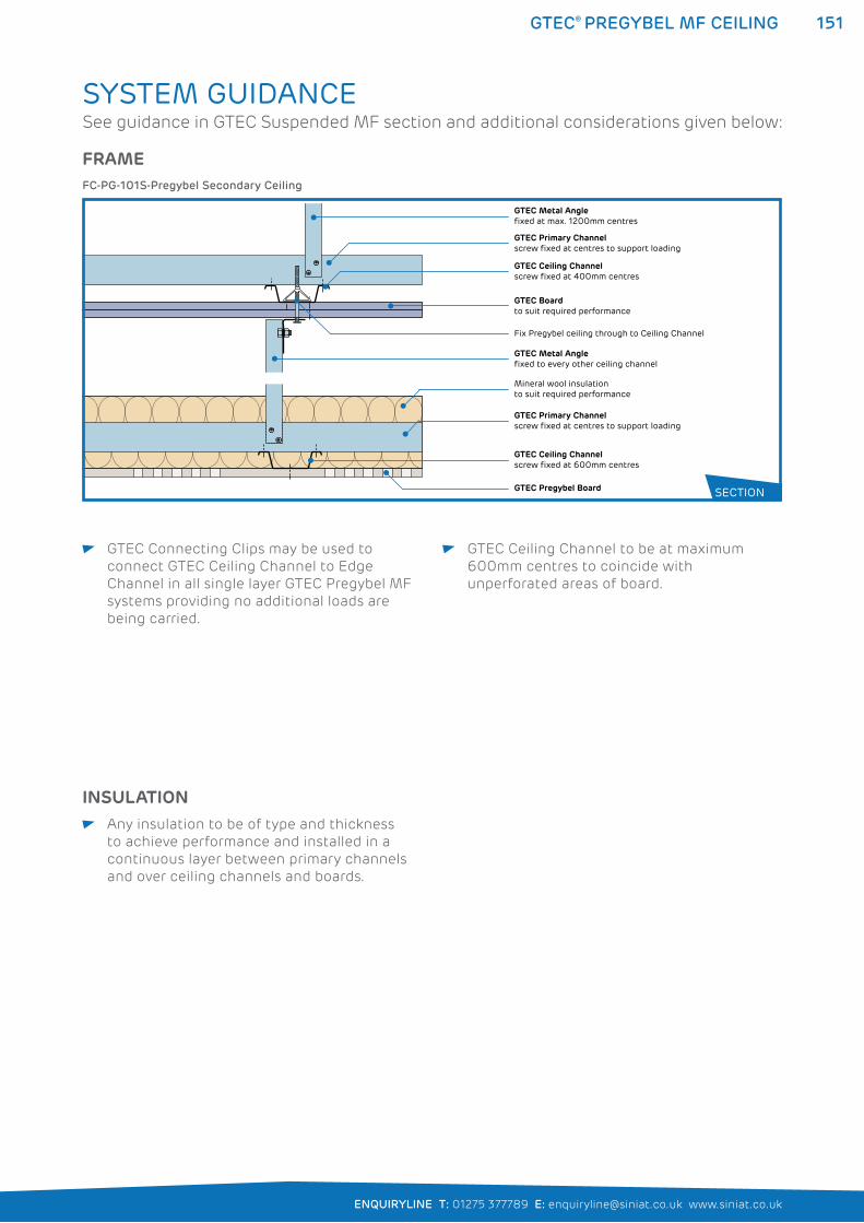
151
ENQUIRYLINE T: 01275 377789 E: [email protected] www.siniat.co.uk
GTEC® PREGYBEL MF CEILING
GTEC Connecting Clips may be used to
connect GTEC Ceiling Channel to Edge
Channel in all single layer GTEC Pregybel MF
systems providing no additional loads are
being carried.
GTEC Ceiling Channel to be at maximum
600mm centres to coincide with
unperforated areas of board.
SYSTEM GUIDANCE
FRAME
GTEC Pregybel Board
GTEC Metal Angle fixed at max. 1200mm centres
GTEC Metal Angle fixed to every other ceiling channel
GTEC Primary Channelscrew fixed at centres to support loading
GTEC Primary Channelscrew fixed at centres to support loading
GTEC Ceiling Channelscrew fixed at 400mm centres
GTEC Ceiling Channelscrew fixed at 600mm centres
GTEC Boardto suit required performance
Fix Pregybel ceiling through to Ceiling Channel
Mineral wool insulationto suit required performance
FC-PG-101S-Pregybel Secondary Ceiling
SECTION
INSULATION Any insulation to be of type and thickness
to achieve performance and installed in a
continuous layer between primary channels
and over ceiling channels and boards.
See guidance in GTEC Suspended MF section and additional considerations given below:
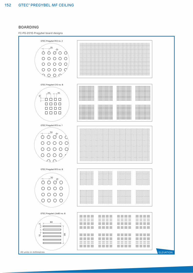
152 GTEC® PREGYBEL MF CEILING
BOARDING
GTEC Pregybel C10 no. 8
GTEC Pregybel R12 no. 2
GTEC Pregybel R15 no. 1
GTEC Pregybel R15 no. 8
GTEC Pregybel L5x80 no. 8
105
80
80
3015
3015
2512
20 10
10
FC-PG-201E-Pregybel board designs
All units in millimetres ELEVATION
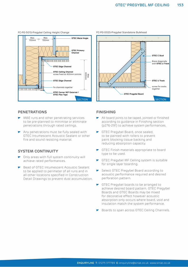
153
ENQUIRYLINE T: 01275 377789 E: [email protected] www.siniat.co.uk
GTEC® PREGYBEL MF CEILING
GTEC Metal Angle
GTEC Primary Channel
GTEC Ceiling Channelscrew fixed at 400mm centres
GTEC Edge Channel
GTEC Edge Channel
GTEC Corner 90º External /GTEC Flex Tape
fix channels together
Max. 150mm
Max.
60
0m
m
Max. 150mm
FC-PG-501S-Pregybel Ceiling Height Change
Brace diagonally with GTEC U Track
GTEC C Stud
GTEC U Track
screw fix tracks together
GTEC Pregybel Board
FC-PG-002S-Pregybel Standalone Bulkhead
SECTION SECTION
SYSTEM CONTINUITY Only areas with full system continuity will
achieve rated performances.
Bead of GTEC Intumescent Acoustic Sealant
to be applied to perimeter of all runs and in
all other locations specified in Construction
Detail Drawings to prevent dust accumulation.
PENETRATIONS M&E runs and other penetrating services
to be pre-planned to minimise or eliminate
penetrations through rated ceilings.
Any penetrations must be fully sealed with
GTEC Intumescent Acoustic Sealant or other
fire and sound resisting material.
FINISHING All board joints to be taped, jointed or finished
according to guidance in Finishing section
(p276-291) to achieve system performances.
GTEC Pregybel Board, once sealed,
to be painted with rollers to prevent
paint blocking tissue backing and
reducing absorption capacity.
GTEC Finish materials appropriate to board
type to be used.
GTEC Pregybel MF Ceiling system is suitable
for single layer boarding.
Select GTEC Pregybel Board according to
acoustic performance required and desired
perforation pattern.
GTEC Pregybel boards to be arranged to
achieve desired board pattern. GTEC Pregybel
Boards and GTEC Boards may be mixed
for decorative effect however acoustic
absorption only occurs where board, void and
insulation match the system performance.
Boards to span across GTEC Ceiling Channels.
154 GTEC® DRYLINER CEILING
GTEC® DRYLINER CEILING SYSTEMSThe GTEC Dryliner Ceiling system is a simple, quick and
cost-effective method for constructing a true, flat ceiling,
even when connecting to uneven joists or concrete soffits.
It also creates a small cavity to accommodate services.
GTEC Dryliner ceilings are made from GTEC Dryliner Brackets
fixed to the soffit or joists, with GTEC Dryliner Channels secured
to them. The channels provide a strong, level substrate for fixing
the plasterboard. GTEC Dryliner Brackets are available for a range
of cavity depths up to 130mm.
Fire rating and acoustic performance can be enhanced by the
selection of appropriate GTEC Boards. Refer to the System
Performance Tables on page 127 for full details.
WHERE TO USE: GTEC Dryliner Ceilings are used for both domestic and commercial
applications for either new build or renovation projects.
FEATURES BENEFITS
Improved fire protection for timber joists Cost effective solution for achieving required
performance
Creates a cavity Accommodates services without the need to
drill joists
Adjustable brackets Creates a flat surface even with uneven joists
or soffit
Separation from soffit Provides improved acoustic performance
No direct connection between board and joists Reduces risk of plasterboard cracking from
movement of wooden joists
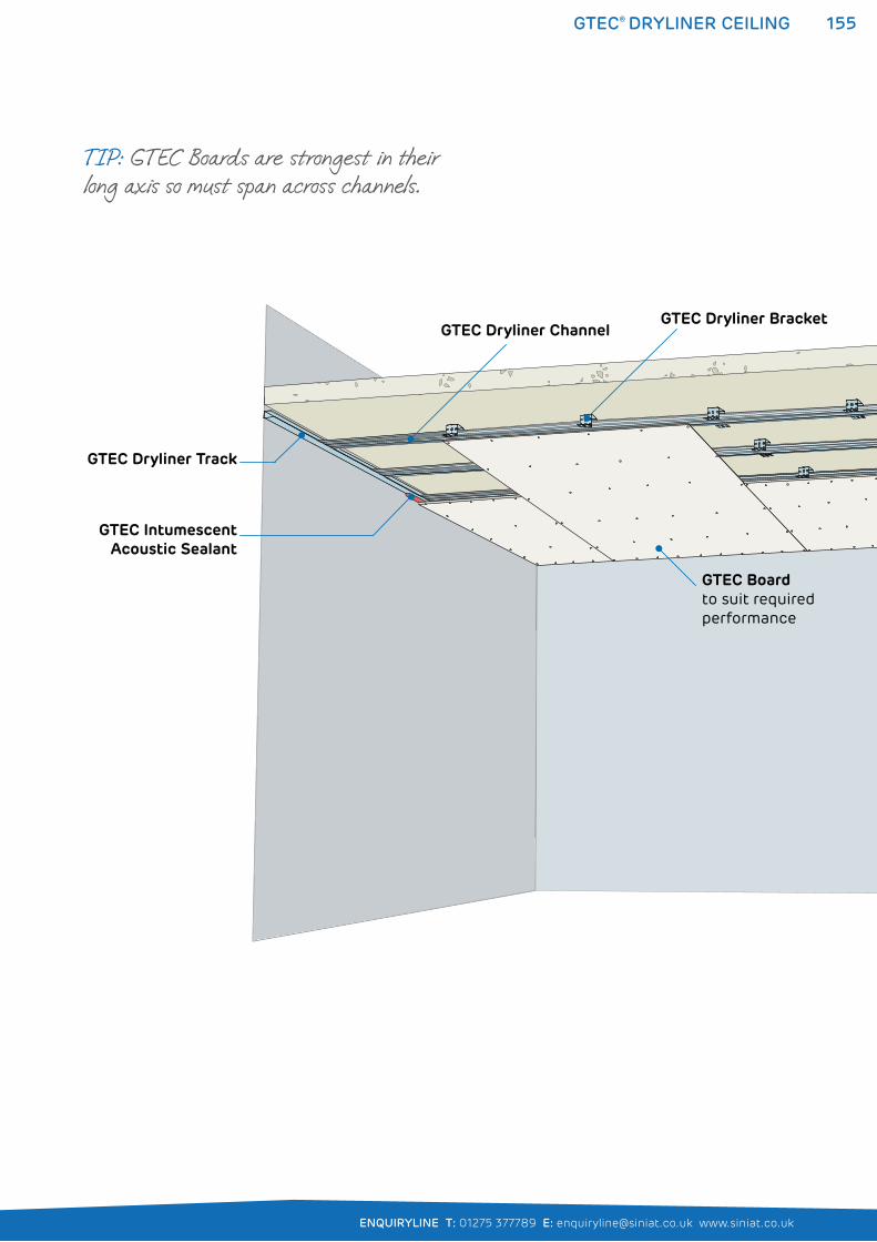
155
ENQUIRYLINE T: 01275 377789 E: [email protected] www.siniat.co.uk
GTEC® DRYLINER CEILING
GTEC Dryliner Track
GTEC Dryliner ChannelGTEC Dryliner Bracket
GTEC Boardto suit required performance
GTEC IntumescentAcoustic Sealant
TIP: GTEC Boards are strongest in their long axis so must span across channels.
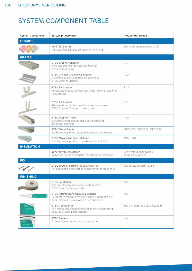
156 GTEC® DRYLINER CEILING
SYSTEM COMPONENT TABLE
System Component System primary use Product Reference
BOARDS
All GTEC Boards
Provides wall surface suitable for finishing
See performance tables, p127
FRAME
GTEC Dryliner Channel
A galvanised steel furring channel for
plasterboard fixing
RD1
GTEC Dryliner Channel Connector
A galvanised clip used to join sections of
GTEC Dryliner Channel
RD3
GTEC SR bracket
Adjustable bracket to connect GTEC Dryliner Channel
to substrate
RD2
GTEC XR bracket
Adjustable, extended reach bracket to connect
GTEC Dryliner Channel to substrate
RD11
GTEC Dryliner Track
J shaped metal section used as a track and
perimeter channel
RD9
GTEC Metal Angle
Multi-purpose metal section as suspension hanger
MFC2330, MFC2525, MFC2550
GTEC Movement Control Joint
Flexible metal profile to create movement joint
MCJ304D
INSULATION
Mineral wool insulation
Increases fire and acoustic insulation performance
See performance tables
supplied by others
FIX
GTEC Drywall Screws (as appropriate)
For connecting plasterboard and metal components
See screw selector, p334
FINISHING
GTEC Joint Tape
Joint reinforcement in conjunction with
GTEC Jointing Compounds
n/a
GTEC Intumescent Acoustic Sealant
Perimeter sealing to restrict smoke, sound and fire
penetration. Ensures system performance
n/a
GTEC Compounds
To finish joints between boards prior to decorating.
Ensures system performance
See compounds guidance, p280
GTEC Sealers
To seal plasterboard prior to decoration
n/a
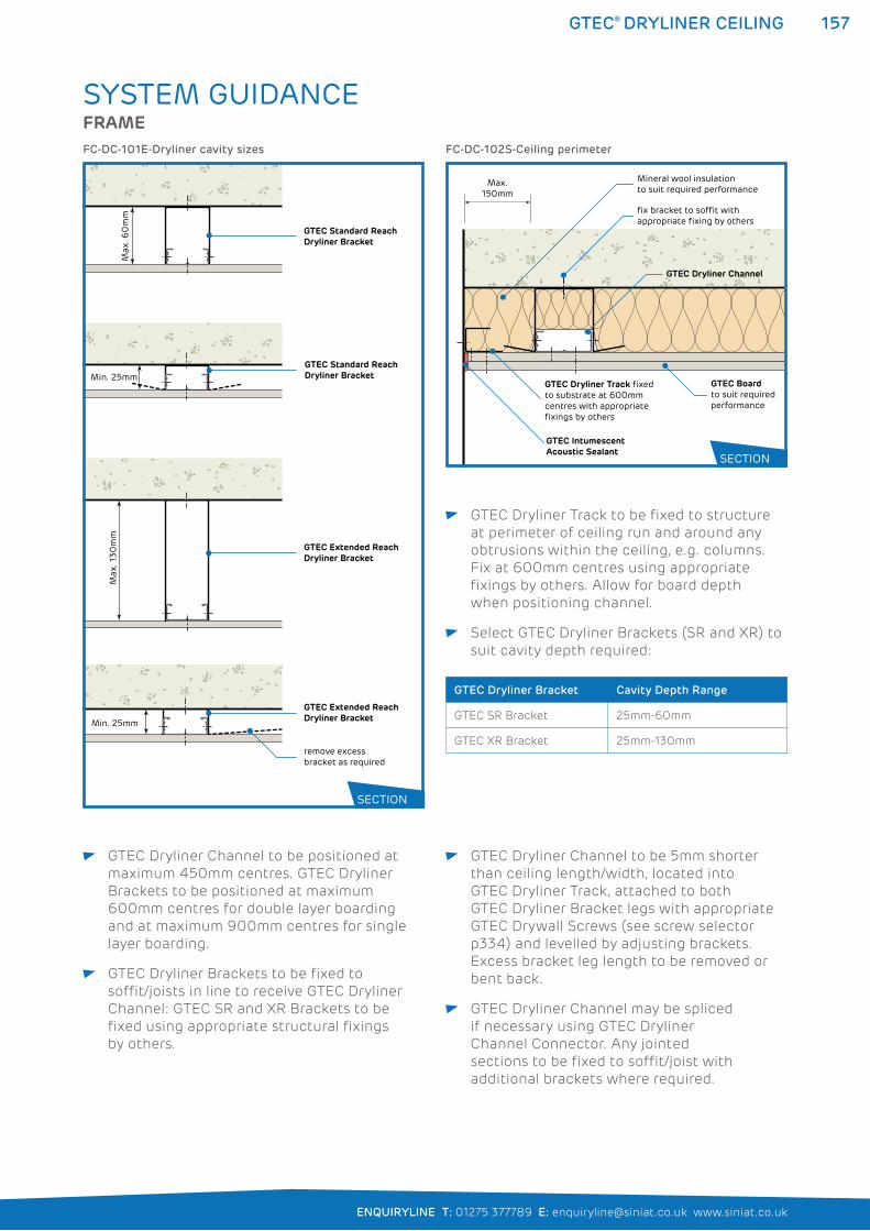
157
ENQUIRYLINE T: 01275 377789 E: [email protected] www.siniat.co.uk
GTEC® DRYLINER CEILING
GTEC Dryliner Track to be fixed to structure
at perimeter of ceiling run and around any
obtrusions within the ceiling, e.g. columns.
Fix at 600mm centres using appropriate
fixings by others. Allow for board depth
when positioning channel.
Select GTEC Dryliner Brackets (SR and XR) to
suit cavity depth required:
GTEC Dryliner Bracket Cavity Depth Range
GTEC SR Bracket 25mm-60mm
GTEC XR Bracket 25mm-130mm
SYSTEM GUIDANCEFRAME
Max
. 60
mm
Min. 25mm
Max
. 130
mm
Min. 25mm
remove excess bracket as required
GTEC Standard Reach Dryliner Bracket
GTEC Standard Reach Dryliner Bracket
GTEC Extended Reach Dryliner Bracket
GTEC Extended Reach Dryliner Bracket
FC-DC-101E-Dryliner cavity sizes
SECTION
fix bracket to soffit with appropriate fixing by others
Mineral wool insulationto suit required performance
GTEC Boardto suit required performance
GTEC Dryliner Channel
GTEC Intumescent Acoustic Sealant
GTEC Dryliner Track fixedto substrate at 600mm centres with appropriate fixings by others
Max. 150mm
FC-DC-102S-Ceiling perimeter
SECTION
GTEC Dryliner Channel to be positioned at
maximum 450mm centres. GTEC Dryliner
Brackets to be positioned at maximum
600mm centres for double layer boarding
and at maximum 900mm centres for single
layer boarding.
GTEC Dryliner Brackets to be fixed to
soffit/joists in line to receive GTEC Dryliner
Channel: GTEC SR and XR Brackets to be
fixed using appropriate structural fixings
by others.
GTEC Dryliner Channel to be 5mm shorter
than ceiling length/width, located into
GTEC Dryliner Track, attached to both
GTEC Dryliner Bracket legs with appropriate
GTEC Drywall Screws (see screw selector
p334) and levelled by adjusting brackets.
Excess bracket leg length to be removed or
bent back.
GTEC Dryliner Channel may be spliced
if necessary using GTEC Dryliner
Channel Connector. Any jointed
sections to be fixed to soffit/joist with
additional brackets where required.
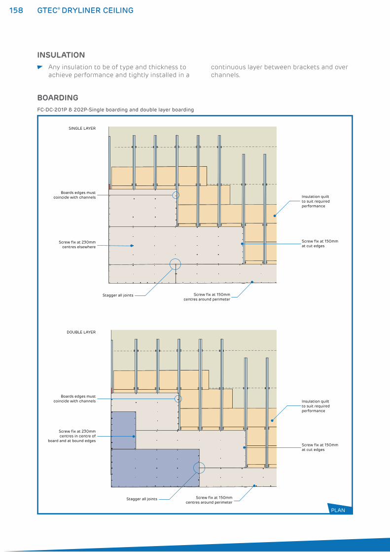
158 GTEC® DRYLINER CEILING
INSULATION Any insulation to be of type and thickness to
achieve performance and tightly installed in a
continuous layer between brackets and over
channels.
BOARDING
Stagger all joints
Screw fix at 150mm at cut edges
Boards edges must coincide with channels
SINGLE LAYER
DOUBLE LAYER
Screw fix at 230mm centres elsewhere
Stagger all joints
Screw fix at 150mm at cut edges
Boards edges must coincide with channels
Screw fix at 150mm centres around perimeter
Screw fix at 230mm centres in centre of
board and at bound edges
Screw fix at 150mm centres around perimeter
Insulation quiltto suit requiredperformance
Insulation quiltto suit requiredperformance
FC-DC-201P & 202P-Single boarding and double layer boarding
PLAN
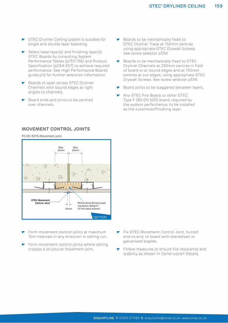
159
ENQUIRYLINE T: 01275 377789 E: [email protected] www.siniat.co.uk
GTEC® DRYLINER CEILING
GTEC Dryliner Ceiling system is suitable for
single and double layer boarding.
Select base layer(s) and finishing layer(s)
GTEC Boards by consulting System
Performance Tables (p133-136) and Product
Specification (p294-307) to achieve required
performance. See High Performance Boards
guide p12 for further selection information.
Boards to span across GTEC Dryliner
Channels with bound edges at right
angles to channels.
Board ends and joints to be centred
over channels.
Boards to be mechanically fixed to
GTEC Dryliner Track at 150mm centres
using appropriate GTEC Drywall Screws.
See screw selector p334.
Boards to be mechanically fixed to GTEC
Dryliner Channels at 230mm centres in field
of board or at bound edges and at 150mm
centres at cut edges, using appropriate GTEC
Drywall Screws. See screw selector p334.
Board joints to be staggered between layers.
Any GTEC Fire Board, or other GTEC
Type F (BS EN 520) board, required by
the system performance, to be installed
as the outermost/finishing layer.
Form movement control joints at maximum
10m intervals in any direction in ceiling run.
Form movement control joints where ceiling
crosses a structural movement joint.
Fix GTEC Movement Control Joint, butted
end-to-end, to board with sheradised or
galvanised staples.
Follow measures to ensure fire resistance and
stability as shown in Construction Details.
MOVEMENT CONTROL JOINTS
Max. 50mm
Max. 50mm
10mm
GTEC MovementControl Joint 50mm Rock Mineral wool
insulation 40kg/m3 (if fire rated system)
FC-DC-301S-Movement joint
SECTION
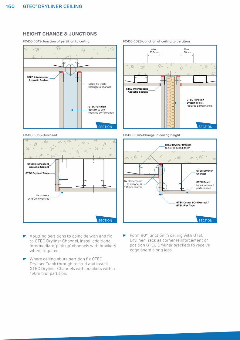
160 GTEC® DRYLINER CEILING
Abutting partitions to coincide with and fix
to GTEC Dryliner Channel, install additional
intermediate ‘pick-up’ channels with brackets
where required.
Where ceiling abuts partition fix GTEC
Dryliner Track through to stud and install
GTEC Dryliner Channels with brackets within
150mm of partition.
Form 90° junction in ceiling with GTEC
Dryliner Track as corner reinforcement or
position GTEC Dryliner brackets to receive
edge board along legs.
fix to track at 150mm centres
GTEC IntumescentAcoustic Sealant
GTEC Dryliner TrackGTEC Dryliner Channel
GTEC Corner 90º External /GTEC Flex Tape
GTEC Dryliner Bracketto suit required depth
GTEC Boardto suit required performance
fix plasterboard to channel at
150mm centres
FC-DC-503S-Bulkhead FC-DC-504S-Change in ceiling height
HEIGHT CHANGE & JUNCTIONS
GTEC IntumescentAcoustic Sealant
screw fix track through to channel
GTEC Partition System to suit required performance
FC-DC-501S-Junction of partition to ceiling
GTEC IntumescentAcoustic Sealant
GTEC Partition System to suit required performance
Max. 150mm
Max. 150mm
FC-DC-502S-Junction of ceiling to partition
SECTION SECTION
SECTION SECTION
161
ENQUIRYLINE T: 01275 377789 E: [email protected] www.siniat.co.uk
GTEC® DRYLINER CEILING
SYSTEM CONTINUITY Full, imperforate system continuity to be
maintained to achieve rated performances.
Bead of GTEC Intumescent Acoustic Sealant
to be applied to perimeter of all runs and in
all other locations specified in Construction
Detail Drawings.
GTEC Intumescent Acoustic Sealant to seal
all other acoustic or air paths to prevent fire/
smoke spread and acoustic transmission.
GTEC Dryliner Ceiling system may be used to
upgrade existing, retained ceilings provided
all fixing is into structural soffit/joists and
any combustible material is removed from
retained ceiling or evaluated as inert.
PENETRATIONS M&E runs and other services to be
pre-planned to minimise or eliminate
penetrations through rated ceilings.
Any penetrations must be fully sealed with
GTEC Intumescent Acoustic Sealant or other
fire and sound resisting material.
FIXTURES Fixtures and loadings to be suspended from
structural soffit/joist and not GTEC Dryliner
Ceiling system.
Any services or installations in ceiling void to
be supported by structural soffit/joist and not
GTEC Dryliner Ceiling System.
FINISHING All board joints to be taped, jointed or
finished according to guidance in Finishing
section (p276-291) to achieve system
performances. Where ceiling is not intended
to be decorated GTEC Intumescent
Sealant to be used to seal board joints.
GTEC Finish materials appropriate to board
type to be used.
162 GTEC® DIRECT-TO-TIMBER CEILING
GTEC® DIRECT-TO-TIMBER CEILING SYSTEMSThe GTEC Direct-to-Timber Ceiling system is the simplest method of
creating a flat ceiling surface for decoration and achieving excellent
fire performance.
GTEC Plasterboard is attached directly to the underside of floor joists
or to the bottom chords of roof trusses with insulation between
rafter to boost acoustic and fire performance. Refer to the System
Performance Tables on pages 122 to 126 for full details.
WHERE TO USE: The GTEC Direct to Timber system is used in both renovation
and new-build domestic applications.
FEATURES BENEFITS
Only requires board and screws Reduces installation time and costs
Compatible with GTEC Board options Achieves required fire performance
Flat finish Provides easy to decorate surface
Can be used with GTEC Resilient Bar Improves acoustic performance and reliability
with some engineered joists
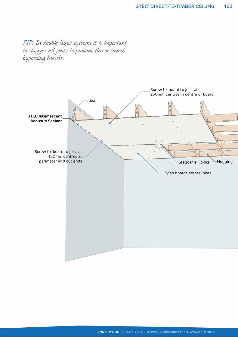
163
ENQUIRYLINE T: 01275 377789 E: [email protected] www.siniat.co.uk
GTEC® DIRECT-TO-TIMBER CEILING
Nogging
Span boards across joists
Joist
Screw fix board to joist at150mm centres at
perimeter and cut ends
Screw fix board to joist at230mm centres in centre of board
Stagger all joints
GTEC IntumescentAcoustic Sealant
TIP: In double layer systems it is important to stagger all joists to prevent fire or sound bypassing boards.
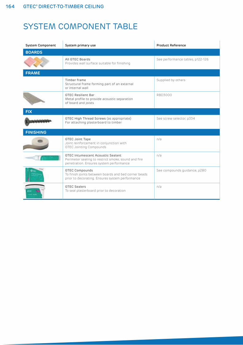
164 GTEC® DIRECT-TO-TIMBER CEILING
SYSTEM COMPONENT TABLE
System Component System primary use Product Reference
BOARDS
All GTEC Boards
Provides wall surface suitable for finishing
See performance tables, p122-126
FRAME
Timber frame
Structural frame forming part of an external or internal wall
Supplied by others
GTEC Resilient Bar
Metal profile to provide acoustic separation of board and joists
RBD3000
FIX
GTEC High Thread Screws (as appropriate)For attaching plasterboard to timber
See screw selector, p334
FINISHING
GTEC Joint Tape
Joint reinforcement in conjunction with
GTEC Jointing Compounds
n/a
GTEC Intumescent Acoustic Sealant
Perimeter sealing to restrict smoke, sound and fire
penetration. Ensures system performance
n/a
GTEC Compounds
To finish joints between boards and bed corner beads
prior to decorating. Ensures system performance
See compounds guidance, p280
GTEC Sealers
To seal plasterboard prior to decoration
n/a
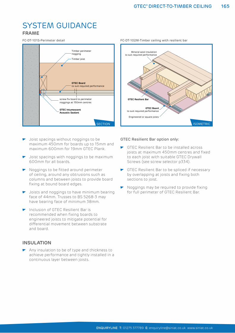
165
ENQUIRYLINE T: 01275 377789 E: [email protected] www.siniat.co.uk
GTEC® DIRECT-TO-TIMBER CEILING
SYSTEM GUIDANCEFRAME
screw fix board to perimeter noggings at 150mm centres
Timber perimeter nogging
Timber joist
GTEC Intumescent Acoustic Sealant
GTEC Boardto suit required performance
FC-DT-101S-Perimeter detail
GTEC Resilient Bar
Mineral wool insulationto suit required performance
Engineered or square joists
GTEC Boardto suit required performance
FC-DT-102M-Timber ceiling with resilient bar
SECTION ISOMETRIC
Joist spacings without noggings to be
maximum 450mm for boards up to 15mm and
maximum 600mm for 19mm GTEC Plank.
Joist spacings with noggings to be maximum
600mm for all boards.
Noggings to be fitted around perimeter
of ceiling, around any obtrusions such as
columns and between joists to provide board
fixing at bound board edges.
Joists and noggings to have minimum bearing
face of 44mm. Trusses to BS 5268-3 may
have bearing face of minimum 38mm.
Inclusion of GTEC Resilient Bar is
recommended when fixing boards to
engineered joists to mitigate potential for
differential movement between substrate
and board.
GTEC Resilient Bar option only:
GTEC Resilient Bar to be installed across
joists at maximum 450mm centres and fixed
to each joist with suitable GTEC Drywall
Screws (see screw selector p334).
GTEC Resilient Bar to be spliced if necessary
by overlapping at joists and fixing both
sections to joist.
Noggings may be required to provide fixing
for full perimeter of GTEC Resilient Bar.
INSULATION Any insulation to be of type and thickness to
achieve performance and tightly installed in a
continuous layer between joists.
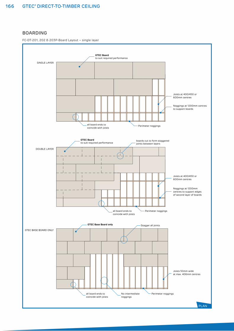
166 GTEC® DIRECT-TO-TIMBER CEILING
BOARDING
all board ends tocoincide with joists
Perimeter noggings
Perimeter noggings
Joists at 400/450 or 600mm centres
Noggings at 1200mm centres to support boards
Joists at 400/450 or 600mm centres
GTEC Boardto suit required performance
SINGLE LAYER
boards cut to form staggered joints between layers
all board ends tocoincide with joists
Noggings at 1200mmcentres to support edges of second layer of boards
GTEC Boardto suit required performance
DOUBLE LAYER
No intermediatenoggings
Perimeter noggings
Joists 50mm wide at max. 406mm centres
Stagger all joints
all board ends tocoincide with joists
GTEC Base Board only
GTEC BASE BOARD ONLY
FC-DT-201, 202 & 203P-Board Layout – single layer
PLAN
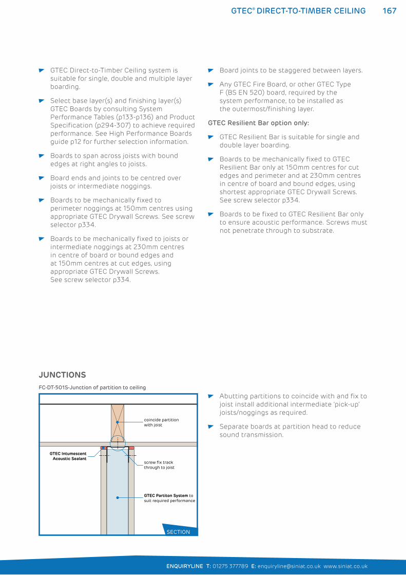
167
ENQUIRYLINE T: 01275 377789 E: [email protected] www.siniat.co.uk
GTEC® DIRECT-TO-TIMBER CEILING
GTEC Direct-to-Timber Ceiling system is
suitable for single, double and multiple layer
boarding.
Select base layer(s) and finishing layer(s)
GTEC Boards by consulting System
Performance Tables (p133-p136) and Product
Specification (p294-307) to achieve required
performance. See High Performance Boards
guide p12 for further selection information.
Boards to span across joists with bound
edges at right angles to joists.
Board ends and joints to be centred over
joists or intermediate noggings.
Boards to be mechanically fixed to
perimeter noggings at 150mm centres using
appropriate GTEC Drywall Screws. See screw
selector p334.
Boards to be mechanically fixed to joists or
intermediate noggings at 230mm centres
in centre of board or bound edges and
at 150mm centres at cut edges, using
appropriate GTEC Drywall Screws.
See screw selector p334.
Board joints to be staggered between layers.
Any GTEC Fire Board, or other GTEC Type
F (BS EN 520) board, required by the
system performance, to be installed as
the outermost/finishing layer.
GTEC Resilient Bar option only:
GTEC Resilient Bar is suitable for single and
double layer boarding.
Boards to be mechanically fixed to GTEC
Resilient Bar only at 150mm centres for cut
edges and perimeter and at 230mm centres
in centre of board and bound edges, using
shortest appropriate GTEC Drywall Screws.
See screw selector p334.
Boards to be fixed to GTEC Resilient Bar only
to ensure acoustic performance. Screws must
not penetrate through to substrate.
Abutting partitions to coincide with and fix to
joist install additional intermediate ‘pick-up’
joists/noggings as required.
Separate boards at partition head to reduce
sound transmission.
JUNCTIONS
GTEC IntumescentAcoustic Sealant
screw fix track through to joist
coincide partition with joist
GTEC Partiton System tosuit required performance
FC-DT-501S-Junction of partition to ceiling
SECTION
168 GTEC® DIRECT-TO-TIMBER CEILING
SYSTEM CONTINUITY Full, imperforate system continuity to be
maintained to achieve rated performances.
Bead of GTEC Intumescent Acoustic Sealant
to be applied to perimeter of all runs and in
all other locations specified in Construction
Detail Drawings.
GTEC Intumescent Acoustic Sealant to seal
all other acoustic or air paths to prevent fire/
smoke spread and acoustic transmission.
PENETRATIONS M&E runs and other services to be
pre-planned to minimise or eliminate
penetrations through rated ceilings.
Any penetrations must be fully sealed with
GTEC Intumescent Acoustic Sealant or other
fire and sound resisting material.
FIXTURES Fixtures and loadings to be suspended from
structural soffit/joist and not GTEC Board.
Services running through ceiling void to be
supported by structural soffit/joist and not
GTEC Board.
FINISHING All board joints to be taped, jointed or finished
according to guidance in Finishing section
(p276-291) to achieve system performances.
Where ceiling is not intended to be decorated
GTEC Intumescent Sealant to be used to seal
board joints.
GTEC Finish materials appropriate to board
type to be used.
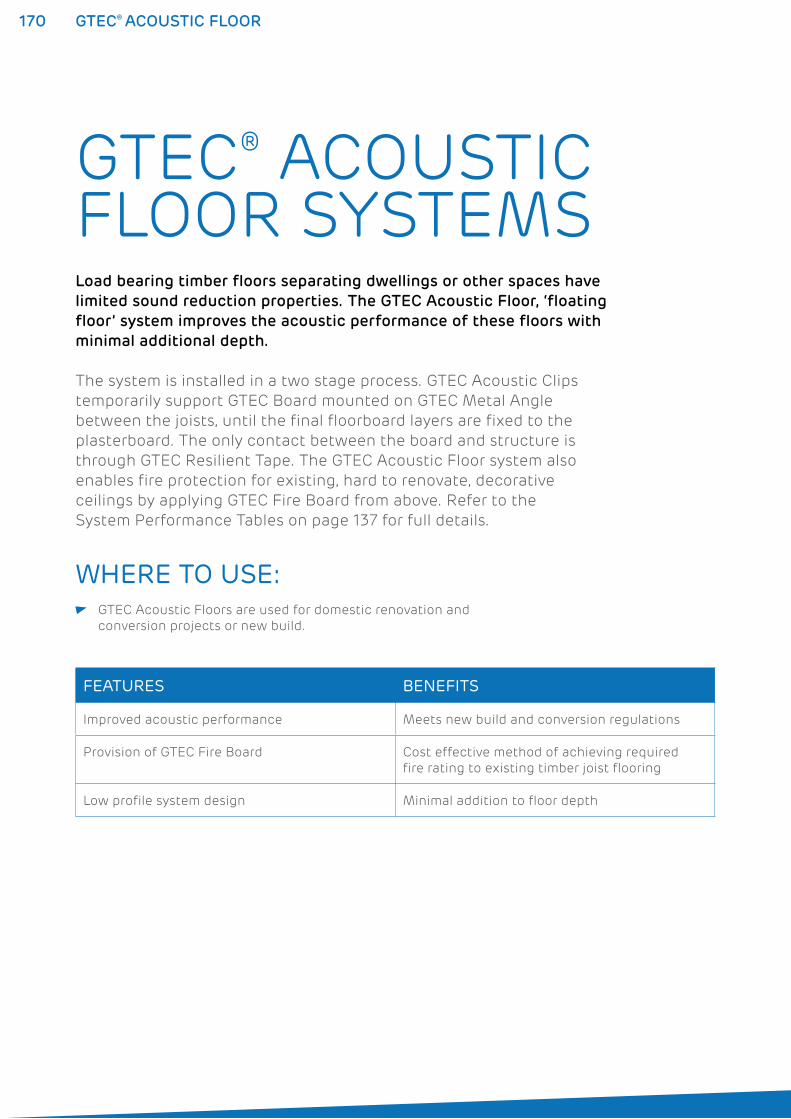
170 GTEC® ACOUSTIC FLOOR
GTEC® ACOUSTIC FLOOR SYSTEMSLoad bearing timber floors separating dwellings or other spaces have
limited sound reduction properties. The GTEC Acoustic Floor, ‘floating
floor’ system improves the acoustic performance of these floors with
minimal additional depth.
The system is installed in a two stage process. GTEC Acoustic Clips
temporarily support GTEC Board mounted on GTEC Metal Angle
between the joists, until the final floorboard layers are fixed to the
plasterboard. The only contact between the board and structure is
through GTEC Resilient Tape. The GTEC Acoustic Floor system also
enables fire protection for existing, hard to renovate, decorative
ceilings by applying GTEC Fire Board from above. Refer to the
System Performance Tables on page 137 for full details.
WHERE TO USE: GTEC Acoustic Floors are used for domestic renovation and
conversion projects or new build.
FEATURES BENEFITS
Improved acoustic performance Meets new build and conversion regulations
Provision of GTEC Fire Board Cost effective method of achieving required
fire rating to existing timber joist flooring
Low profile system design Minimal addition to floor depth
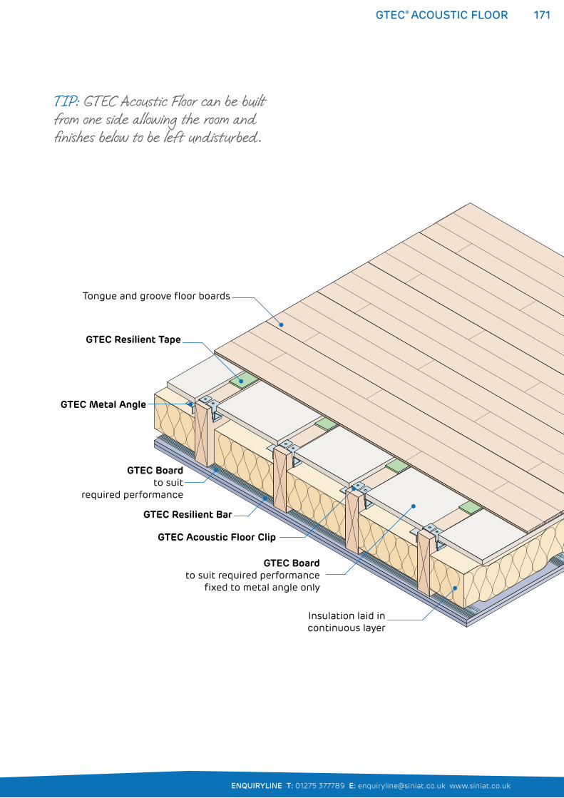
171
ENQUIRYLINE T: 01275 377789 E: [email protected] www.siniat.co.uk
GTEC® ACOUSTIC FLOOR
GTEC Resilient Tape
GTEC Acoustic Floor Clip
GTEC Metal Angle
Insulation laid incontinuous layer
Tongue and groove floor boards
GTEC Boardto suit
required performance
GTEC Board to suit required performance
fixed to metal angle only
GTEC Resilient Bar
TIP: GTEC Acoustic Floor can be built from one side allowing the room and finishes below to be left undisturbed.
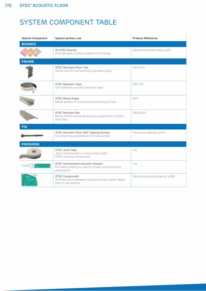
172 GTEC® ACOUSTIC FLOOR
SYSTEM COMPONENT TABLE
System Component System primary use Product Reference
BOARDS
All GTEC Boards
Provides wall surface suitable for finishing
See performance tables, p137
FRAME
GTEC Acoustic Floor Clip
Metal clips for connecting to wooden joists
RACFC25
GTEC Resilient Tape
Self adhesive acoustic isolation tape
RAFT50
GTEC Metal Angle
Metal section to brace joists and acoustic floor
MFC
GTEC Resilient Bar
Metal profile to provide acoustic separation of board
and joists
RBD3000
FIX
GTEC Acoustic Floor Self Tapping Screws
For attaching plasterboard to metal angle
See screw selector, p334
FINISHING
GTEC Joint Tape
Joint reinforcement in conjunction with
GTEC Jointing Compounds
n/a
GTEC Intumescent Acoustic Sealant
Perimeter sealing to restrict smoke, sound and fire
penetration
n/a
GTEC Compounds
To finish joints between boards and bed corner beads
prior to decorating
See compounds guidance, p280
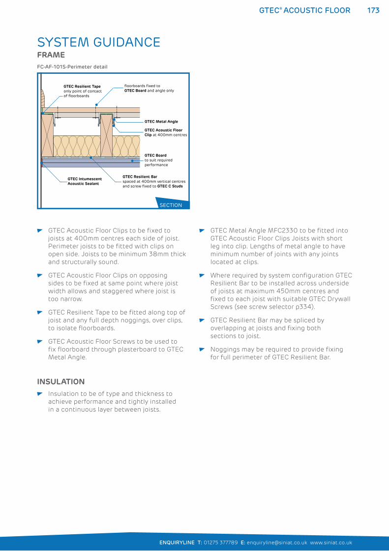
173
ENQUIRYLINE T: 01275 377789 E: [email protected] www.siniat.co.uk
GTEC® ACOUSTIC FLOOR
SYSTEM GUIDANCEFRAME
GTEC Intumescent Acoustic Sealant
GTEC Boardto suit required performance
GTEC Resilient Tapeonly point of contact of floorboards
GTEC Resilient Barspaced at 400mm vertical centresand screw fixed to GTEC C Studs
GTEC Acoustic Floor Clip at 400mm centres
GTEC Metal Angle
floorboards fixed to GTEC Board and angle only
FC-AF-101S-Perimeter detail
SECTION
GTEC Acoustic Floor Clips to be fixed to
joists at 400mm centres each side of joist.
Perimeter joists to be fitted with clips on
open side. Joists to be minimum 38mm thick
and structurally sound.
GTEC Acoustic Floor Clips on opposing
sides to be fixed at same point where joist
width allows and staggered where joist is
too narrow.
GTEC Resilient Tape to be fitted along top of
joist and any full depth noggings, over clips,
to isolate floorboards.
GTEC Acoustic Floor Screws to be used to
fix floorboard through plasterboard to GTEC
Metal Angle.
GTEC Metal Angle MFC2330 to be fitted into
GTEC Acoustic Floor Clips Joists with short
leg into clip. Lengths of metal angle to have
minimum number of joints with any joints
located at clips.
Where required by system configuration GTEC
Resilient Bar to be installed across underside
of joists at maximum 450mm centres and
fixed to each joist with suitable GTEC Drywall
Screws (see screw selector p334).
GTEC Resilient Bar may be spliced by
overlapping at joists and fixing both
sections to joist.
Noggings may be required to provide fixing
for full perimeter of GTEC Resilient Bar.
INSULATION Insulation to be of type and thickness to
achieve performance and tightly installed
in a continuous layer between joists.
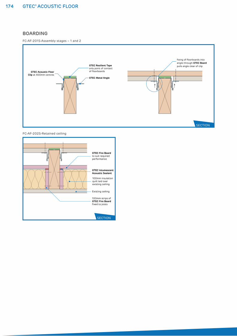
174 GTEC® ACOUSTIC FLOOR
GTEC Fire Boardto suit required performance
100mm insulation quilt laid over existing ceiling
100mm strips of GTEC Fire Boardfixed to joists
Existing ceiling
GTEC Intumescent Acoustic Sealant
FC-AF-202S-Retained ceiling
BOARDING
GTEC Acoustic FloorClip at 400mm centres
GTEC Resilient Tapeonly point of contact of floorboards
GTEC Metal Angle
fixing of floorboards intoangle through GTEC Board pulls angle clear of clip
FC-AF-201S-Assembly stages – 1 and 2
SECTION
SECTION
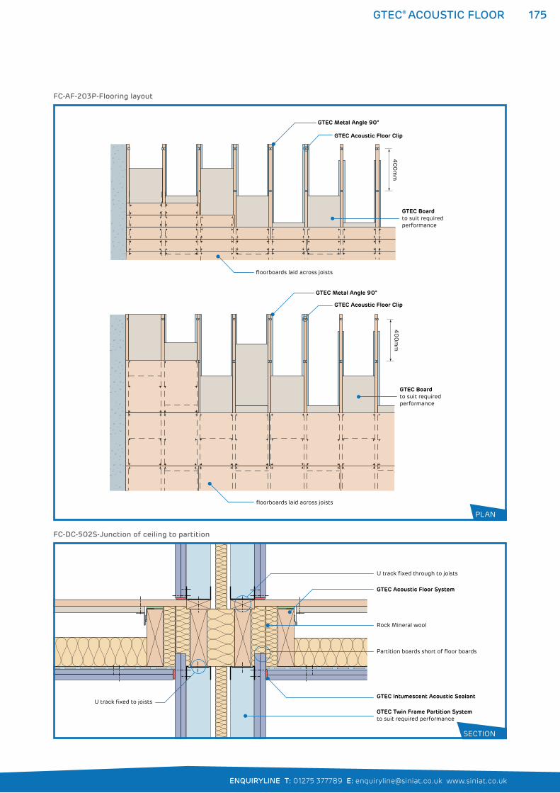
175
ENQUIRYLINE T: 01275 377789 E: [email protected] www.siniat.co.uk
GTEC® ACOUSTIC FLOOR
40
0m
m4
00
mm
GTEC Boardto suit required performance
GTEC Boardto suit required performance
floorboards laid across joists
floorboards laid across joists
GTEC Acoustic Floor Clip
GTEC Metal Angle 90°
GTEC Acoustic Floor Clip
GTEC Metal Angle 90°
FC-AF-203P-Flooring layout
GTEC Twin Frame Partition Systemto suit required performance
GTEC Intumescent Acoustic Sealant
Partition boards short of floor boards
U track fixed through to joists
Rock Mineral wool
GTEC Acoustic Floor System
U track fixed to joists
FC-DC-502S-Junction of ceiling to partition
SECTION
PLAN
176 GTEC® ACOUSTIC FLOOR
SYSTEM CONTINUITY Full, imperforate system continuity to be
maintained to achieve rated performances.
Bead of GTEC Intumescent Acoustic Sealant
to be applied to perimeter of all runs and in
all other locations specified in Construction
Detail Drawings.
GTEC Intumescent Acoustic Sealant to seal
all other acoustic or air paths to prevent fire/
smoke spread and acoustic transmission.
PENETRATIONS M&E runs and other services to be
pre-planned to minimise or eliminate
penetrations through rated ceilings.
Any penetrations must be fully sealed
with GTEC Intumescent Acoustic Sealant
or other fire and sound resisting material.
Boarding to underside of ceiling to follow
guidance in GTEC Direct-to-Timber section
p162-169.
Where required by retained ceiling system
configuration 100mm strips of 15mm
GTEC Fire Board to be fitted along each
side of joists. Further 15mm GTEC Fire
Board to be installed to bridge from strip
to strip providing a continuous barrier
between joists.
Select GTEC Board as required by system
performance cut 4mm shorter than space
between joists, to be temporarily secured
to GTEC Metal Angle only at approx.
600mm centres.
Floorboards to be installed across joists
and fixed through GTEC Board to GTEC
Metal Angle both sides of every joist
using appropriate GTEC Acoustic Floor
Screws in pattern shown in Construction
Detail drawing. Free-floating floor is
created when angle is pulled out of
clips during fixing of floorboards and
GTEC Board to GTEC Metal Angle.
Floorboards to be in contact with
GTEC Resilient Tape only.
Floorboards to be 3mm clear of perimeter
wall and sealed with GTEC Acoustic
Intumescent Sealant.
Softwood floorboards may require gluing
to a plywood base to prevent warping.
BOARDING continued

GTEC® LININGS178
179
ENQUIRYLINE T: 01275 377789 E: [email protected] www.siniat.co.uk
LININGS
System Performance Tables
GTEC Lining Systems to New External Walls 180
GTEC Lining Systems to Upgrade Internal Walls 182
GTEC Lining Systems to Thermally Upgrade External Walls 184
GTEC Lining Systems to Framed External Walls 187
GTEC Pregybel Independent Lining Systems 190
GTEC GTEC Direct Bond Linings 192
GTEC Contour Linings 202
GTEC Shallow Channel Linings 208
GTEC Dryliner Linings 216
GTEC Independent Wall Linings 226
GTEC Pregybel Independent Linings 236
GTEC Lining systems offer a wide range of plasterboard lining fixing systems to walls and roofs for most typical substrates. Different depths of cavity spaces can be created between the GTEC Board or GTEC Thermal Board lining and underlying wall. These cavities hide services or help to achieve high levels of fire resistance, U-Values and sound insulation.
179
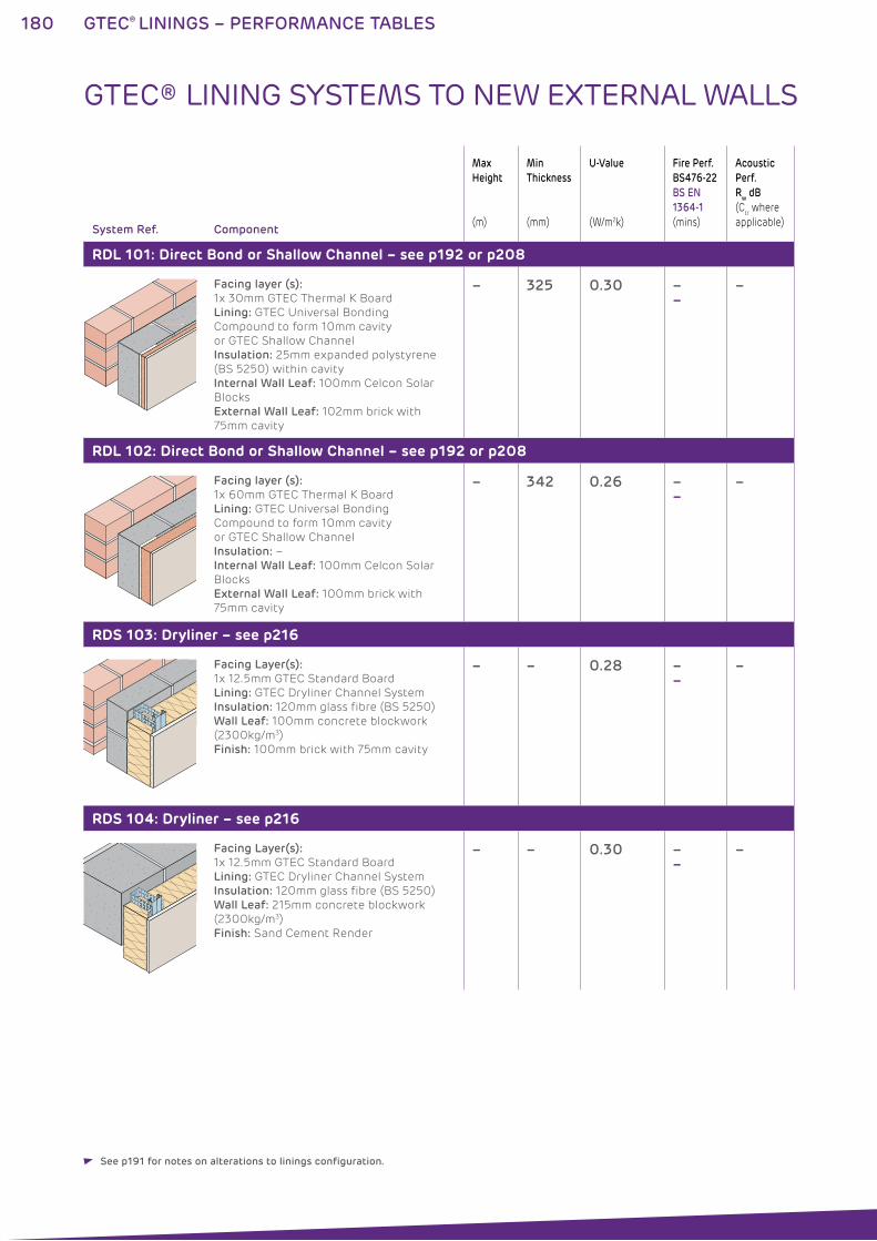
180 GTEC® LININGS – PERFORMANCE TABLES
System Ref. Component
Max
Height
(m)
Min
Thickness
(mm)
U-Value
(W/m2k)
Fire Perf.
BS476-22
BS EN
1364-1
(mins)
Acoustic
Perf.
Rw dB
(Ctr where
applicable)
RDL 101: Direct Bond or Shallow Channel – see p192 or p208
Facing layer (s):
1x 30mm GTEC Thermal K Board
Lining: GTEC Universal Bonding
Compound to form 10mm cavity
or GTEC Shallow Channel
Insulation: 25mm expanded polystyrene
(BS 5250) within cavity
Internal Wall Leaf: 100mm Celcon Solar
Blocks
External Wall Leaf: 102mm brick with
75mm cavity
– 325 0.30 ––
–
RDL 102: Direct Bond or Shallow Channel – see p192 or p208
Facing layer (s):
1x 60mm GTEC Thermal K Board
Lining: GTEC Universal Bonding
Compound to form 10mm cavity
or GTEC Shallow Channel
Insulation: –
Internal Wall Leaf: 100mm Celcon Solar
Blocks
External Wall Leaf: 100mm brick with
75mm cavity
– 342 0.26 ––
–
RDS 103: Dryliner – see p216
Facing Layer(s):
1x 12.5mm GTEC Standard Board
Lining: GTEC Dryliner Channel System
Insulation: 120mm glass fibre (BS 5250)
Wall Leaf: 100mm concrete blockwork
(2300kg/m3)
Finish: 100mm brick with 75mm cavity
– – 0.28 ––
–
RDS 104: Dryliner – see p216
Facing Layer(s):
1x 12.5mm GTEC Standard Board
Lining: GTEC Dryliner Channel System
Insulation: 120mm glass fibre (BS 5250)
Wall Leaf: 215mm concrete blockwork
(2300kg/m3)
Finish: Sand Cement Render
– – 0.30 ––
–
GTEC® LINING SYSTEMS TO NEW EXTERNAL WALLS
See p191 for notes on alterations to linings configuration.
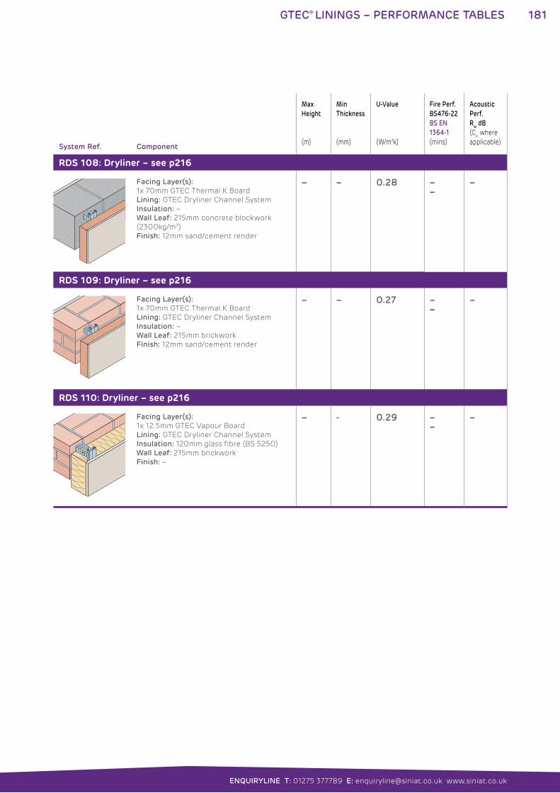
181GTEC® LININGS – PERFORMANCE TABLES
ENQUIRYLINE T: 01275 377789 E: [email protected] www.siniat.co.uk
System Ref. Component
Max
Height
(m)
Min
Thickness
(mm)
U-Value
(W/m2k)
Fire Perf.
BS476-22
BS EN
1364-1
(mins)
Acoustic
Perf.
Rw dB
(Ctr where
applicable)
RDS 108: Dryliner – see p216
Facing Layer(s):
1x 70mm GTEC Thermal K Board
Lining: GTEC Dryliner Channel System
Insulation: –
Wall Leaf: 215mm concrete blockwork
(2300kg/m3)
Finish: 12mm sand/cement render
– – 0.28 ––
–
RDS 109: Dryliner – see p216
Facing Layer(s):
1x 70mm GTEC Thermal K Board
Lining: GTEC Dryliner Channel System
Insulation: –
Wall Leaf: 215mm brickwork
Finish: 12mm sand/cement render
– – 0.27 ––
–
RDS 110: Dryliner – see p216
Facing Layer(s):
1x 12.5mm GTEC Vapour Board
Lining: GTEC Dryliner Channel System
Insulation: 120mm glass fibre (BS 5250)
Wall Leaf: 215mm brickwork
Finish: –
– - 0.29 ––
–
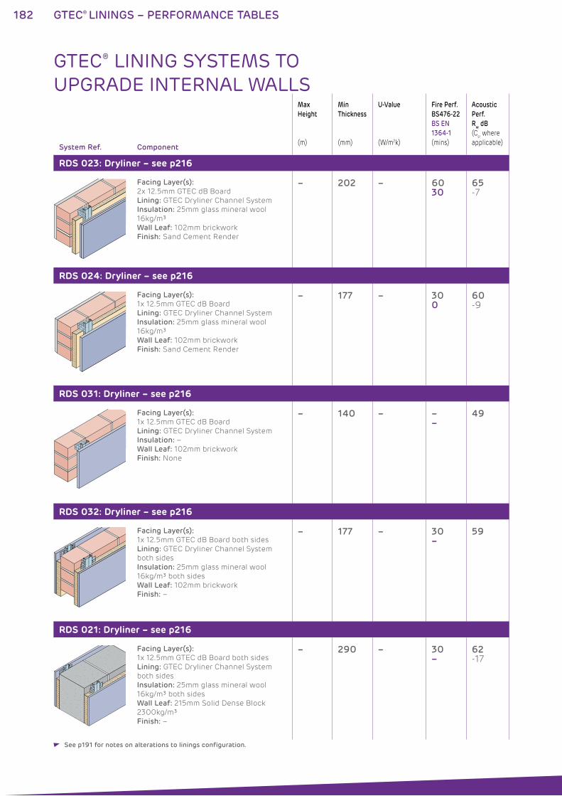
182 GTEC® LININGS – PERFORMANCE TABLES
System Ref. Component
Max
Height
(m)
Min
Thickness
(mm)
U-Value
(W/m2k)
Fire Perf.
BS476-22
BS EN
1364-1
(mins)
Acoustic
Perf.
Rw dB
(Ctr where
applicable)
RDS 023: Dryliner – see p216
Facing Layer(s):
2x 12.5mm GTEC dB Board
Lining: GTEC Dryliner Channel System
Insulation: 25mm glass mineral wool
16kg/m³
Wall Leaf: 102mm brickwork
Finish: Sand Cement Render
– 202 – 6030
65 -7
RDS 024: Dryliner – see p216
Facing Layer(s):
1x 12.5mm GTEC dB Board
Lining: GTEC Dryliner Channel System
Insulation: 25mm glass mineral wool
16kg/m³
Wall Leaf: 102mm brickwork
Finish: Sand Cement Render
– 177 – 300
60 -9
RDS 031: Dryliner – see p216
Facing Layer(s):
1x 12.5mm GTEC dB Board
Lining: GTEC Dryliner Channel System
Insulation: –
Wall Leaf: 102mm brickwork
Finish: None
– 140 – ––
49
RDS 032: Dryliner – see p216
Facing Layer(s):
1x 12.5mm GTEC dB Board both sides
Lining: GTEC Dryliner Channel System
both sides
Insulation: 25mm glass mineral wool
16kg/m³ both sides
Wall Leaf: 102mm brickwork
Finish: –
– 177 – 30–
59
RDS 021: Dryliner – see p216
Facing Layer(s):
1x 12.5mm GTEC dB Board both sides
Lining: GTEC Dryliner Channel System
both sides
Insulation: 25mm glass mineral wool
16kg/m³ both sides
Wall Leaf: 215mm Solid Dense Block
2300kg/m³
Finish: –
– 290 – 30–
62 -17
GTEC® LINING SYSTEMS TO UPGRADE INTERNAL WALLS
See p191 for notes on alterations to linings configuration.
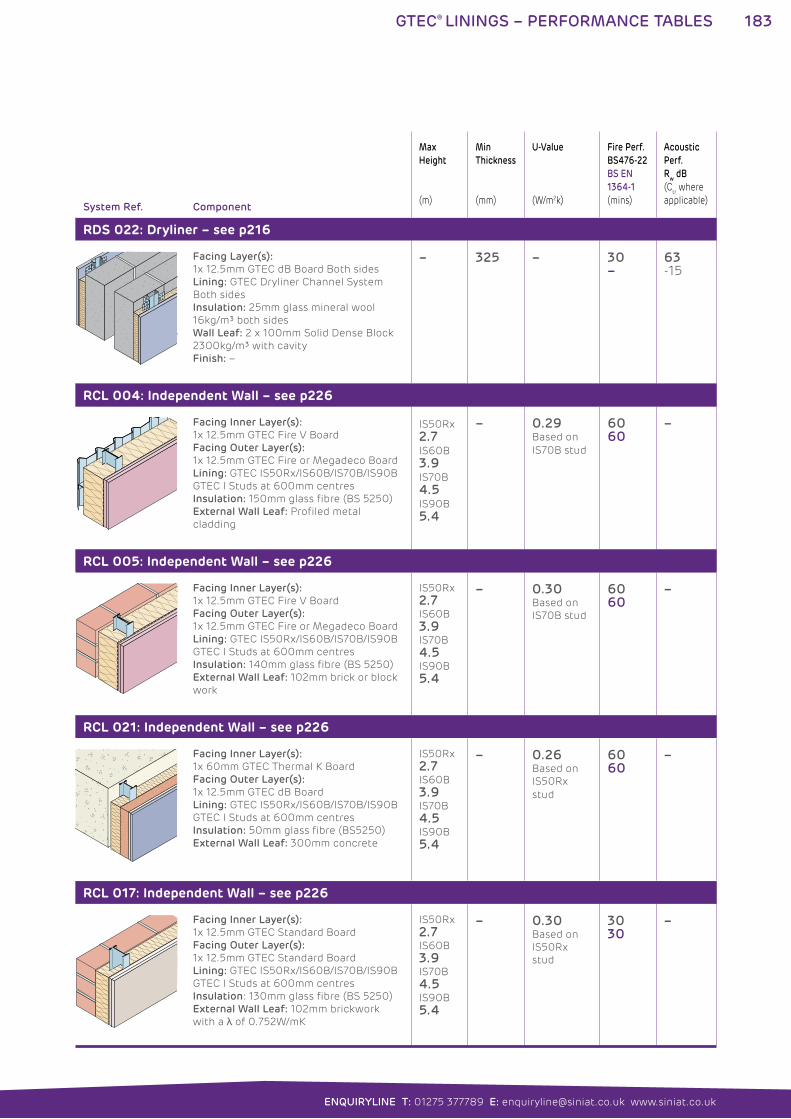
183GTEC® LININGS – PERFORMANCE TABLES
ENQUIRYLINE T: 01275 377789 E: [email protected] www.siniat.co.uk
System Ref. Component
Max
Height
(m)
Min
Thickness
(mm)
U-Value
(W/m2k)
Fire Perf.
BS476-22
BS EN
1364-1
(mins)
Acoustic
Perf.
Rw dB
(Ctr where
applicable)
RDS 022: Dryliner – see p216
Facing Layer(s):
1x 12.5mm GTEC dB Board Both sides
Lining: GTEC Dryliner Channel System
Both sides
Insulation: 25mm glass mineral wool
16kg/m³ both sides
Wall Leaf: 2 x 100mm Solid Dense Block
2300kg/m³ with cavity
Finish: –
– 325 – 30–
63 -15
RCL 004: Independent Wall – see p226
Facing Inner Layer(s):
1x 12.5mm GTEC Fire V Board
Facing Outer Layer(s):
1x 12.5mm GTEC Fire or Megadeco Board
Lining: GTEC IS50Rx/IS60B/IS70B/IS90B
GTEC I Studs at 600mm centres
Insulation: 150mm glass fibre (BS 5250)
External Wall Leaf: Profiled metal
cladding
IS50Rx 2.7IS60B 3.9IS70B 4.5IS90B 5.4
– 0.29Based on
IS70B stud
6060
–
RCL 005: Independent Wall – see p226
Facing Inner Layer(s):
1x 12.5mm GTEC Fire V Board
Facing Outer Layer(s):
1x 12.5mm GTEC Fire or Megadeco Board
Lining: GTEC IS50Rx/IS60B/IS70B/IS90B
GTEC I Studs at 600mm centres
Insulation: 140mm glass fibre (BS 5250)
External Wall Leaf: 102mm brick or block
work
IS50Rx
2.7IS60B
3.9IS70B
4.5IS90B
5.4
– 0.30Based on
IS70B stud
6060
–
RCL 021: Independent Wall – see p226
Facing Inner Layer(s):
1x 60mm GTEC Thermal K Board
Facing Outer Layer(s):
1x 12.5mm GTEC dB Board
Lining: GTEC IS50Rx/IS60B/IS70B/IS90B
GTEC I Studs at 600mm centres
Insulation: 50mm glass fibre (BS5250)
External Wall Leaf: 300mm concrete
IS50Rx
2.7IS60B
3.9IS70B
4.5IS90B
5.4
– 0.26Based on
IS50Rx
stud
6060
–
RCL 017: Independent Wall – see p226
Facing Inner Layer(s):
1x 12.5mm GTEC Standard Board
Facing Outer Layer(s):
1x 12.5mm GTEC Standard Board
Lining: GTEC IS50Rx/IS60B/IS70B/IS90B
GTEC I Studs at 600mm centres
Insulation: 130mm glass fibre (BS 5250)
External Wall Leaf: 102mm brickwork
with a of 0.752W/mK
IS50Rx
2.7IS60B
3.9IS70B
4.5IS90B
5.4
– 0.30Based on
IS50Rx
stud
3030
–
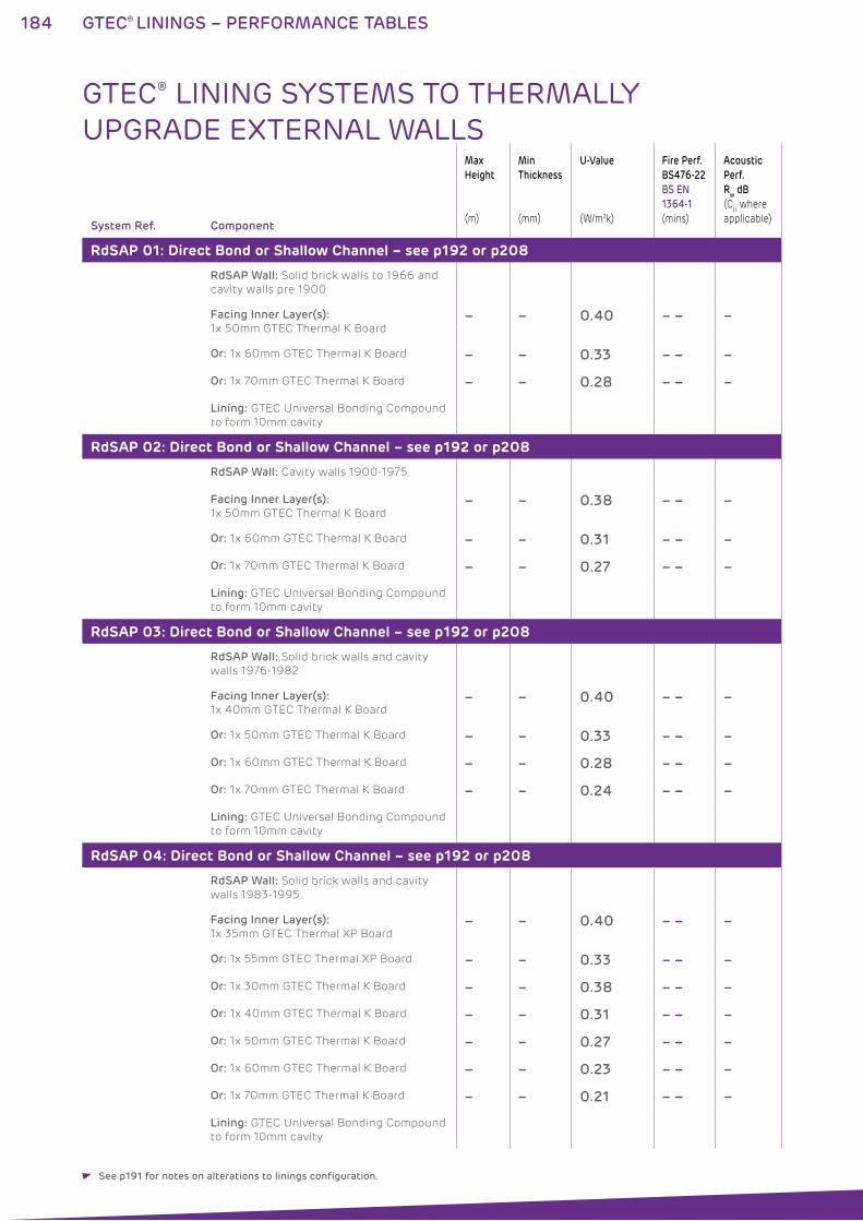
184 GTEC® LININGS – PERFORMANCE TABLES
System Ref. Component
Max
Height
(m)
Min
Thickness
(mm)
U-Value
(W/m2k)
Fire Perf.
BS476-22
BS EN
1364-1
(mins)
Acoustic
Perf.
Rw dB
(Ctr where
applicable)
RdSAP 01: Direct Bond or Shallow Channel – see p192 or p208
RdSAP Wall: Solid brick walls to 1966 and
cavity walls pre 1900
Facing Inner Layer(s):
1x 50mm GTEC Thermal K Board– – 0.40 – – –
Or: 1x 60mm GTEC Thermal K Board – – 0.33 – – –
Or: 1x 70mm GTEC Thermal K Board – – 0.28 – – –
Lining: GTEC Universal Bonding Compound
to form 10mm cavity
RdSAP 02: Direct Bond or Shallow Channel – see p192 or p208
RdSAP Wall: Cavity walls 1900-1975
Facing Inner Layer(s):
1x 50mm GTEC Thermal K Board– – 0.38 – – –
Or: 1x 60mm GTEC Thermal K Board – – 0.31 – – –
Or: 1x 70mm GTEC Thermal K Board – – 0.27 – – –
Lining: GTEC Universal Bonding Compound
to form 10mm cavity
RdSAP 03: Direct Bond or Shallow Channel – see p192 or p208
RdSAP Wall: Solid brick walls and cavity
walls 1976-1982
Facing Inner Layer(s):
1x 40mm GTEC Thermal K Board– – 0.40 – – –
Or: 1x 50mm GTEC Thermal K Board – – 0.33 – – –
Or: 1x 60mm GTEC Thermal K Board – – 0.28 – – –
Or: 1x 70mm GTEC Thermal K Board – – 0.24 – – –
Lining: GTEC Universal Bonding Compound
to form 10mm cavity
RdSAP 04: Direct Bond or Shallow Channel – see p192 or p208
RdSAP Wall: Solid brick walls and cavity
walls 1983-1995
Facing Inner Layer(s):
1x 35mm GTEC Thermal XP Board– – 0.40 – – –
Or: 1x 55mm GTEC Thermal XP Board – – 0.33 – – –
Or: 1x 30mm GTEC Thermal K Board – – 0.38 – – –
Or: 1x 40mm GTEC Thermal K Board – – 0.31 – – –
Or: 1x 50mm GTEC Thermal K Board – – 0.27 – – –
Or: 1x 60mm GTEC Thermal K Board – – 0.23 – – –
Or: 1x 70mm GTEC Thermal K Board – – 0.21 – – –
Lining: GTEC Universal Bonding Compound
to form 10mm cavity
GTEC® LINING SYSTEMS TO THERMALLY UPGRADE EXTERNAL WALLS
See p191 for notes on alterations to linings configuration.
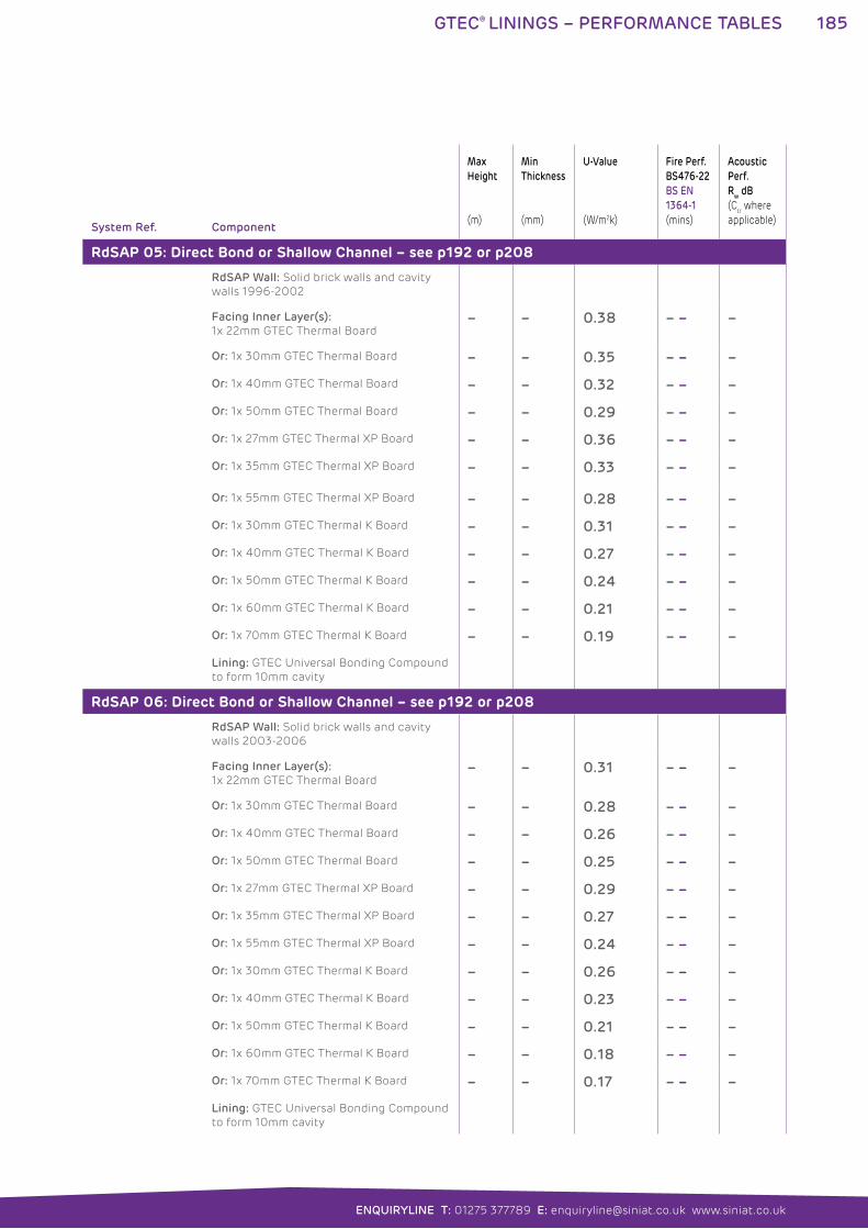
185GTEC® LININGS – PERFORMANCE TABLES
ENQUIRYLINE T: 01275 377789 E: [email protected] www.siniat.co.uk
System Ref. Component
Max
Height
(m)
Min
Thickness
(mm)
U-Value
(W/m2k)
Fire Perf.
BS476-22
BS EN
1364-1
(mins)
Acoustic
Perf.
Rw dB
(Ctr where
applicable)
RdSAP 05: Direct Bond or Shallow Channel – see p192 or p208
RdSAP Wall: Solid brick walls and cavity
walls 1996-2002
Facing Inner Layer(s):
1x 22mm GTEC Thermal Board– – 0.38 – – –
Or: 1x 30mm GTEC Thermal Board – – 0.35 – – –
Or: 1x 40mm GTEC Thermal Board – – 0.32 – – –
Or: 1x 50mm GTEC Thermal Board – – 0.29 – – –
Or: 1x 27mm GTEC Thermal XP Board – – 0.36 – – –
Or: 1x 35mm GTEC Thermal XP Board – – 0.33 – – –
Or: 1x 55mm GTEC Thermal XP Board – – 0.28 – – –
Or: 1x 30mm GTEC Thermal K Board – – 0.31 – – –
Or: 1x 40mm GTEC Thermal K Board – – 0.27 – – –
Or: 1x 50mm GTEC Thermal K Board – – 0.24 – – –
Or: 1x 60mm GTEC Thermal K Board – – 0.21 – – –
Or: 1x 70mm GTEC Thermal K Board – – 0.19 – – –
Lining: GTEC Universal Bonding Compound
to form 10mm cavity
RdSAP 06: Direct Bond or Shallow Channel – see p192 or p208
RdSAP Wall: Solid brick walls and cavity
walls 2003-2006
Facing Inner Layer(s):
1x 22mm GTEC Thermal Board– – 0.31 – – –
Or: 1x 30mm GTEC Thermal Board – – 0.28 – – –
Or: 1x 40mm GTEC Thermal Board – – 0.26 – – –
Or: 1x 50mm GTEC Thermal Board – – 0.25 – – –
Or: 1x 27mm GTEC Thermal XP Board – – 0.29 – – –
Or: 1x 35mm GTEC Thermal XP Board – – 0.27 – – –
Or: 1x 55mm GTEC Thermal XP Board – – 0.24 – – –
Or: 1x 30mm GTEC Thermal K Board – – 0.26 – – –
Or: 1x 40mm GTEC Thermal K Board – – 0.23 – – –
Or: 1x 50mm GTEC Thermal K Board – – 0.21 – – –
Or: 1x 60mm GTEC Thermal K Board – – 0.18 – – –
Or: 1x 70mm GTEC Thermal K Board – – 0.17 – – –
Lining: GTEC Universal Bonding Compound
to form 10mm cavity
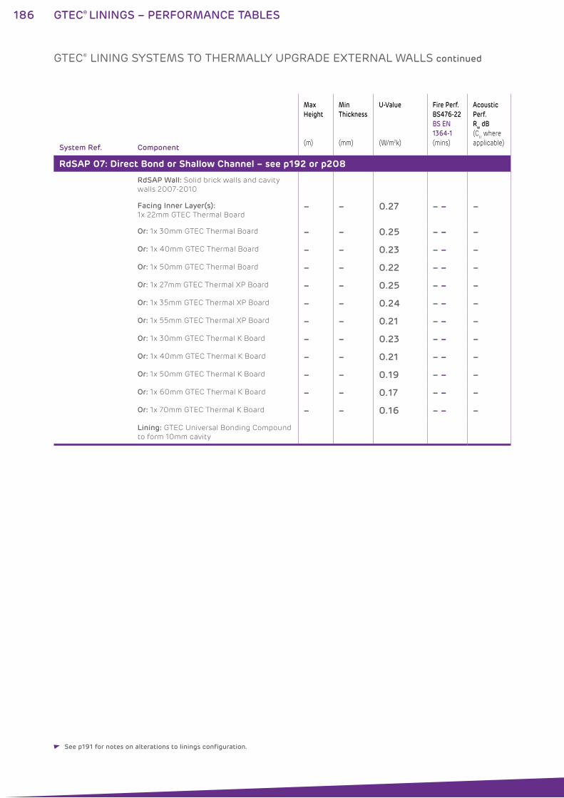
186 GTEC® LININGS – PERFORMANCE TABLES
System Ref. Component
Max
Height
(m)
Min
Thickness
(mm)
U-Value
(W/m2k)
Fire Perf.
BS476-22
BS EN
1364-1
(mins)
Acoustic
Perf.
Rw dB
(Ctr where
applicable)
RdSAP 07: Direct Bond or Shallow Channel – see p192 or p208
RdSAP Wall: Solid brick walls and cavity
walls 2007-2010
Facing Inner Layer(s):
1x 22mm GTEC Thermal Board– – 0.27 – – –
Or: 1x 30mm GTEC Thermal Board – – 0.25 – – –
Or: 1x 40mm GTEC Thermal Board – – 0.23 – – –
Or: 1x 50mm GTEC Thermal Board – – 0.22 – – –
Or: 1x 27mm GTEC Thermal XP Board – – 0.25 – – –
Or: 1x 35mm GTEC Thermal XP Board – – 0.24 – – –
Or: 1x 55mm GTEC Thermal XP Board – – 0.21 – – –
Or: 1x 30mm GTEC Thermal K Board – – 0.23 – – –
Or: 1x 40mm GTEC Thermal K Board – – 0.21 – – –
Or: 1x 50mm GTEC Thermal K Board – – 0.19 – – –
Or: 1x 60mm GTEC Thermal K Board – – 0.17 – – –
Or: 1x 70mm GTEC Thermal K Board – – 0.16 – – –
Lining: GTEC Universal Bonding Compound
to form 10mm cavity
GTEC® LINING SYSTEMS TO THERMALLY UPGRADE EXTERNAL WALLS continued
See p191 for notes on alterations to linings configuration.
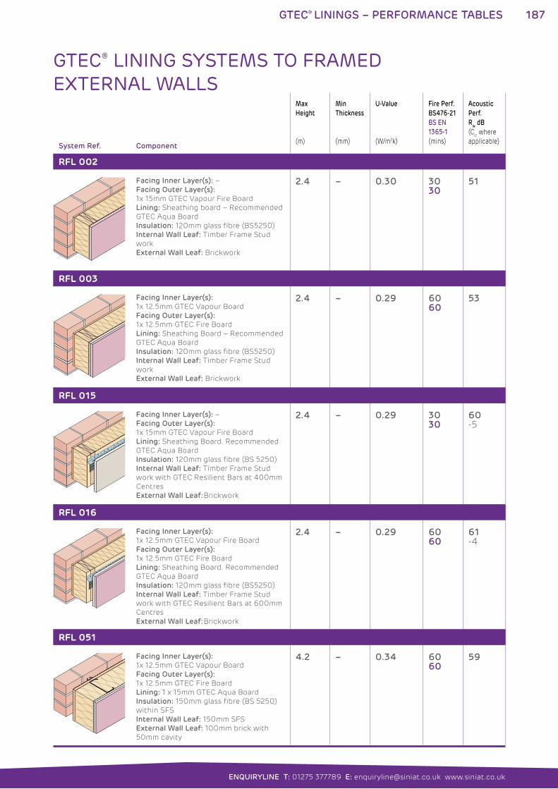
187GTEC® LININGS – PERFORMANCE TABLES
ENQUIRYLINE T: 01275 377789 E: [email protected] www.siniat.co.uk
System Ref. Component
Max
Height
(m)
Min
Thickness
(mm)
U-Value
(W/m2k)
Fire Perf.
BS476-21
BS EN
1365-1
(mins)
Acoustic
Perf.
Rw dB
(Ctr where
applicable)
RFL 002
Facing Inner Layer(s): –
Facing Outer Layer(s):
1x 15mm GTEC Vapour Fire Board
Lining: Sheathing board – Recommended
GTEC Aqua Board
Insulation: 120mm glass fibre (BS5250)
Internal Wall Leaf: Timber Frame Stud
work
External Wall Leaf: Brickwork
2.4 – 0.30 3030
51
RFL 003
Facing Inner Layer(s):
1x 12.5mm GTEC Vapour Board
Facing Outer Layer(s):
1x 12.5mm GTEC Fire Board
Lining: Sheathing Board – Recommended
GTEC Aqua Board
Insulation: 120mm glass fibre (BS5250)
Internal Wall Leaf: Timber Frame Stud
work
External Wall Leaf: Brickwork
2.4 – 0.29 6060
53
RFL 015
Facing Inner Layer(s): –
Facing Outer Layer(s):
1x 15mm GTEC Vapour Fire Board
Lining: Sheathing Board. Recommended
GTEC Aqua Board
Insulation: 120mm glass fibre (BS 5250)
Internal Wall Leaf: Timber Frame Stud
work with GTEC Resilient Bars at 400mm
Centres
External Wall Leaf: Brickwork
2.4 – 0.29 3030
60-5
RFL 016
Facing Inner Layer(s):
1x 12.5mm GTEC Vapour Fire Board
Facing Outer Layer(s):
1x 12.5mm GTEC Fire Board
Lining: Sheathing Board. Recommended
GTEC Aqua Board
Insulation: 120mm glass fibre (BS5250)
Internal Wall Leaf: Timber Frame Stud
work with GTEC Resilient Bars at 600mm
Centres
External Wall Leaf: Brickwork
2.4 – 0.29 6060
61-4
RFL 051
Facing Inner Layer(s):
1x 12.5mm GTEC Vapour Board
Facing Outer Layer(s):
1x 12.5mm GTEC Fire Board
Lining: 1 x 15mm GTEC Aqua Board
Insulation: 150mm glass fibre (BS 5250)
within SFS
Internal Wall Leaf: 150mm SFS
External Wall Leaf: 100mm brick with
50mm cavity
4.2 – 0.34 6060
59
GTEC® LINING SYSTEMS TO FRAMED EXTERNAL WALLS
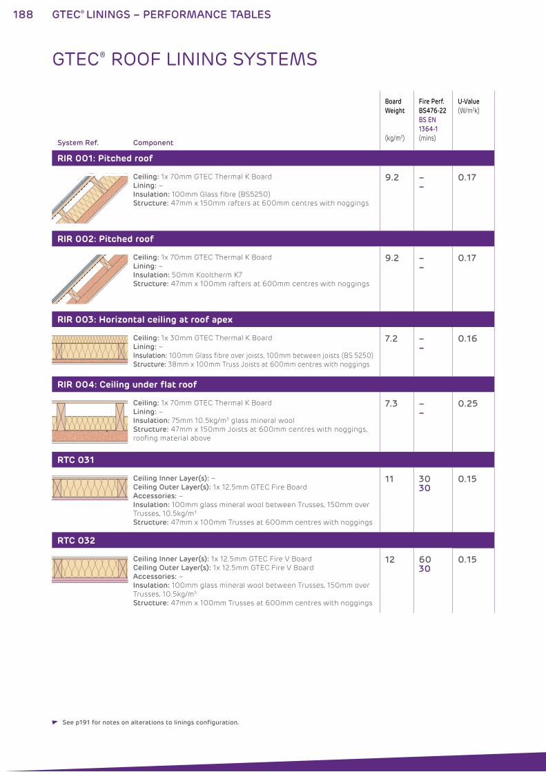
188 GTEC® LININGS – PERFORMANCE TABLES
System Ref. Component
Board
Weight
(kg/m2)
Fire Perf.
BS476-22
BS EN
1364-1
(mins)
U-Value
(W/m2k)
RIR 001: Pitched roof
Ceiling: 1x 70mm GTEC Thermal K Board
Lining: –
Insulation: 100mm Glass fibre (BS5250)
Structure: 47mm x 150mm rafters at 600mm centres with noggings
9.2 ––
0.17
RIR 002: Pitched roof
Ceiling: 1x 70mm GTEC Thermal K Board
Lining: –
Insulation: 50mm Kooltherm K7
Structure: 47mm x 100mm rafters at 600mm centres with noggings
9.2 ––
0.17
RIR 003: Horizontal ceiling at roof apex
Ceiling: 1x 30mm GTEC Thermal K Board
Lining: –
Insulation: 100mm Glass fibre over joists, 100mm between joists (BS 5250)
Structure: 38mm x 100mm Truss Joists at 600mm centres with noggings
7.2 ––
0.16
RIR 004: Ceiling under flat roof
Ceiling: 1x 70mm GTEC Thermal K Board
Lining: –
Insulation: 75mm 10.5kg/m3 glass mineral wool
Structure: 47mm x 150mm Joists at 600mm centres with noggings,
roofing material above
7.3 ––
0.25
RTC 031
Ceiling Inner Layer(s): –
Ceiling Outer Layer(s): 1x 12.5mm GTEC Fire Board
Accessories: –
Insulation: 100mm glass mineral wool between Trusses, 150mm over
Trusses, 10.5kg/m3
Structure: 47mm x 100mm Trusses at 600mm centres with noggings
11 3030
0.15
RTC 032
Ceiling Inner Layer(s): 1x 12.5mm GTEC Fire V Board
Ceiling Outer Layer(s): 1x 12.5mm GTEC Fire V Board
Accessories: –
Insulation: 100mm glass mineral wool between Trusses, 150mm over
Trusses, 10.5kg/m3
Structure: 47mm x 100mm Trusses at 600mm centres with noggings
12 6030
0.15
GTEC® ROOF LINING SYSTEMS
See p191 for notes on alterations to linings configuration.
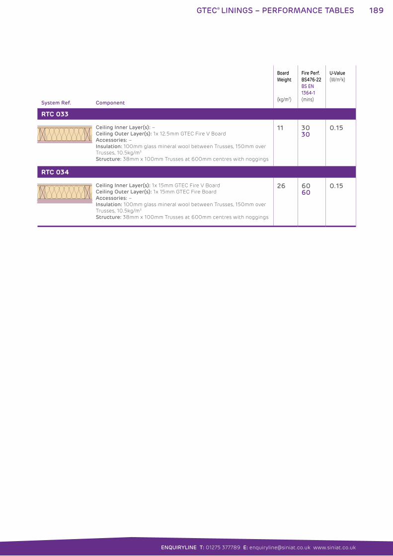
189GTEC® LININGS – PERFORMANCE TABLES
ENQUIRYLINE T: 01275 377789 E: [email protected] www.siniat.co.uk
System Ref. Component
Board
Weight
(kg/m2)
Fire Perf.
BS476-22
BS EN
1364-1
(mins)
U-Value
(W/m2k)
RTC 033
Ceiling Inner Layer(s): –
Ceiling Outer Layer(s): 1x 12.5mm GTEC Fire V Board
Accessories: –
Insulation: 100mm glass mineral wool between Trusses, 150mm over
Trusses, 10.5kg/m3
Structure: 38mm x 100mm Trusses at 600mm centres with noggings
11 3030
0.15
RTC 034
Ceiling Inner Layer(s): 1x 15mm GTEC Fire V Board
Ceiling Outer Layer(s): 1x 15mm GTEC Fire Board
Accessories: –
Insulation: 100mm glass mineral wool between Trusses, 150mm over
Trusses, 10.5kg/m3
Structure: 38mm x 100mm Trusses at 600mm centres with noggings
26 6060
0.15
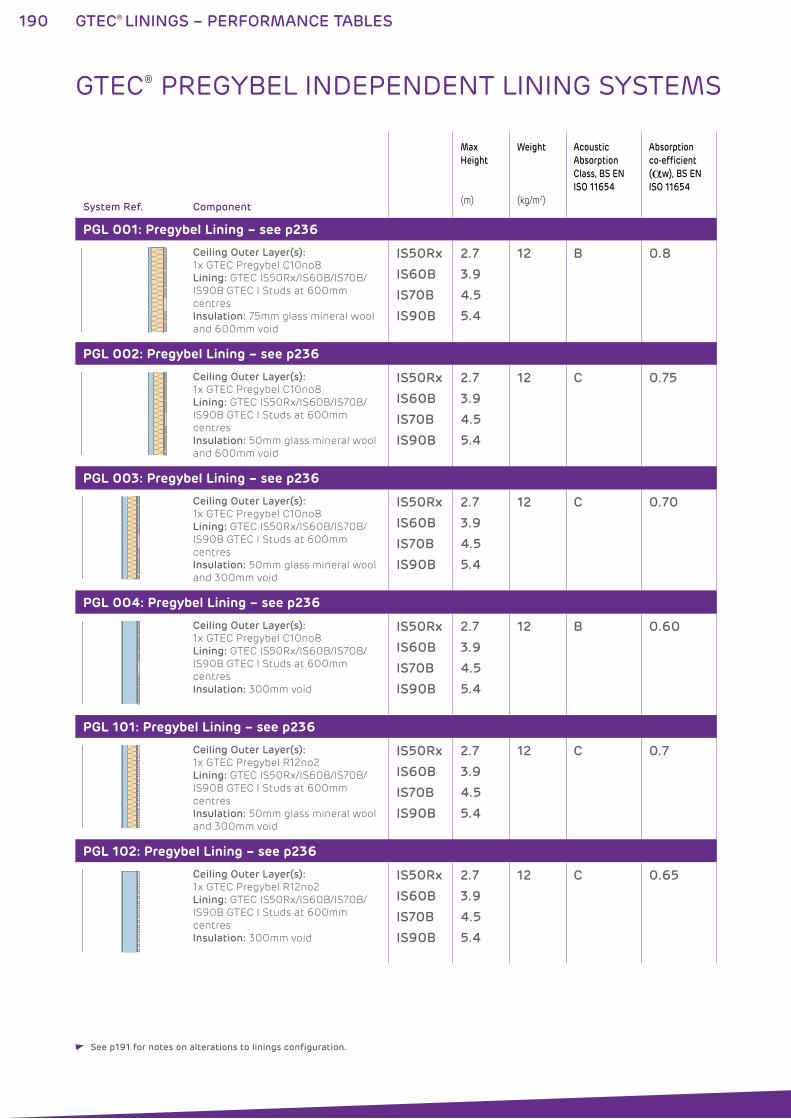
190 GTEC® LININGS – PERFORMANCE TABLES
System Ref. Component
Max
Height
(m)
Weight
(kg/m2)
Acoustic
Absorption
Class, BS EN
ISO 11654
Absorption
co-efficient
(�w), BS EN
ISO 11654
PGL 001: Pregybel Lining – see p236
Ceiling Outer Layer(s):
1x GTEC Pregybel C10no8
Lining: GTEC IS50Rx/IS60B/IS70B/
IS90B GTEC I Studs at 600mm
centres
Insulation: 75mm glass mineral wool
and 600mm void
IS50Rx
IS60B
IS70B
IS90B
2.7
3.9
4.5
5.4
12 B 0.8
PGL 002: Pregybel Lining – see p236
Ceiling Outer Layer(s):
1x GTEC Pregybel C10no8
Lining: GTEC IS50Rx/IS60B/IS70B/
IS90B GTEC I Studs at 600mm
centres
Insulation: 50mm glass mineral wool
and 600mm void
IS50Rx
IS60B
IS70B
IS90B
2.7
3.9
4.5
5.4
12 C 0.75
PGL 003: Pregybel Lining – see p236
Ceiling Outer Layer(s):
1x GTEC Pregybel C10no8
Lining: GTEC IS50Rx/IS60B/IS70B/
IS90B GTEC I Studs at 600mm
centres
Insulation: 50mm glass mineral wool
and 300mm void
IS50Rx
IS60B
IS70B
IS90B
2.7
3.9
4.5
5.4
12 C 0.70
PGL 004: Pregybel Lining – see p236
Ceiling Outer Layer(s):
1x GTEC Pregybel C10no8
Lining: GTEC IS50Rx/IS60B/IS70B/
IS90B GTEC I Studs at 600mm
centres
Insulation: 300mm void
IS50Rx
IS60B
IS70B
IS90B
2.7
3.9
4.5
5.4
12 B 0.60
PGL 101: Pregybel Lining – see p236
Ceiling Outer Layer(s):
1x GTEC Pregybel R12no2
Lining: GTEC IS50Rx/IS60B/IS70B/
IS90B GTEC I Studs at 600mm
centres
Insulation: 50mm glass mineral wool
and 300mm void
IS50Rx
IS60B
IS70B
IS90B
2.7
3.9
4.5
5.4
12 C 0.7
PGL 102: Pregybel Lining – see p236
Ceiling Outer Layer(s):
1x GTEC Pregybel R12no2
Lining: GTEC IS50Rx/IS60B/IS70B/
IS90B GTEC I Studs at 600mm
centres
Insulation: 300mm void
IS50Rx
IS60B
IS70B
IS90B
2.7
3.9
4.5
5.4
12 C 0.65
GTEC® PREGYBEL INDEPENDENT LINING SYSTEMS
See p191 for notes on alterations to linings configuration.
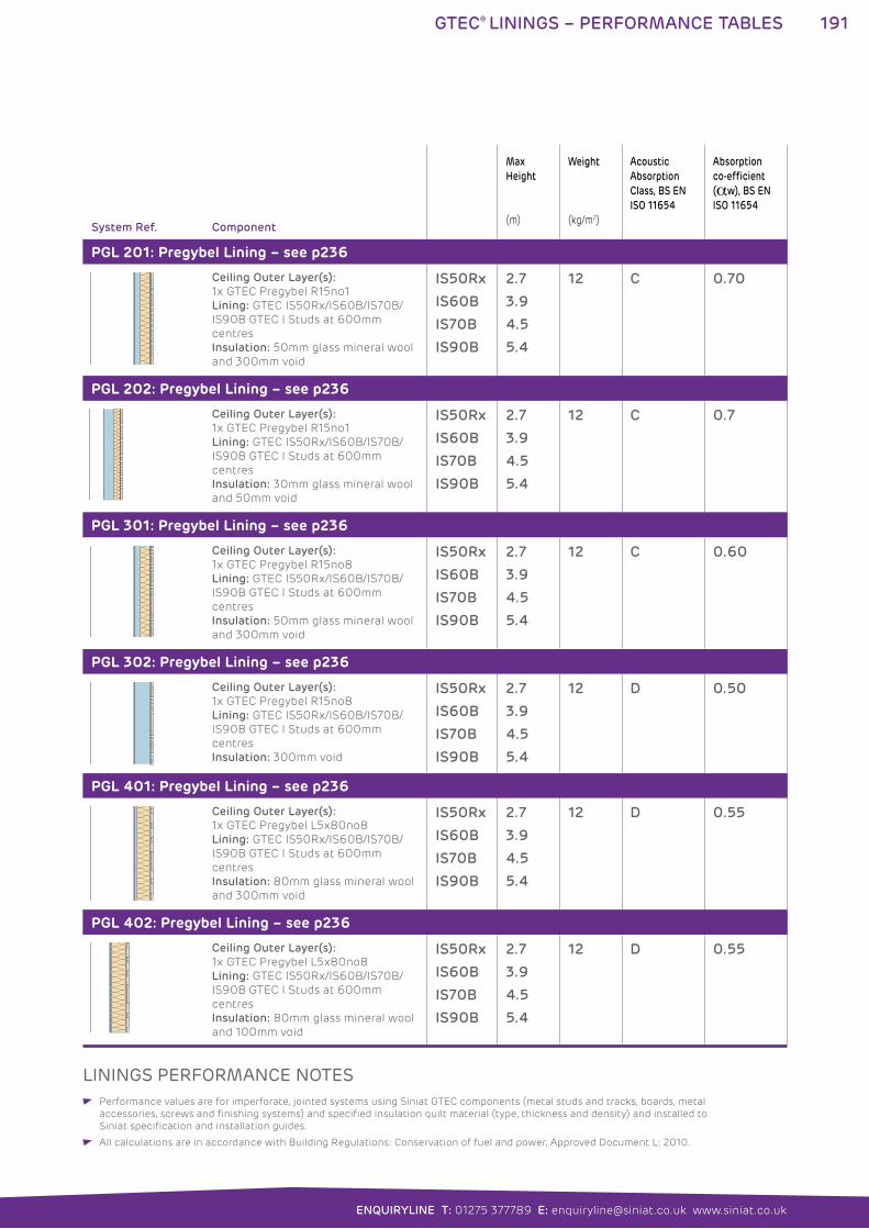
191GTEC® LININGS – PERFORMANCE TABLES
ENQUIRYLINE T: 01275 377789 E: [email protected] www.siniat.co.uk
System Ref. Component
Max
Height
(m)
Weight
(kg/m2)
Acoustic
Absorption
Class, BS EN
ISO 11654
Absorption
co-efficient
(�w), BS EN
ISO 11654
PGL 201: Pregybel Lining – see p236
Ceiling Outer Layer(s):
1x GTEC Pregybel R15no1
Lining: GTEC IS50Rx/IS60B/IS70B/
IS90B GTEC I Studs at 600mm
centres
Insulation: 50mm glass mineral wool
and 300mm void
IS50Rx
IS60B
IS70B
IS90B
2.7
3.9
4.5
5.4
12 C 0.70
PGL 202: Pregybel Lining – see p236
Ceiling Outer Layer(s):
1x GTEC Pregybel R15no1
Lining: GTEC IS50Rx/IS60B/IS70B/
IS90B GTEC I Studs at 600mm
centres
Insulation: 30mm glass mineral wool
and 50mm void
IS50Rx
IS60B
IS70B
IS90B
2.7
3.9
4.5
5.4
12 C 0.7
PGL 301: Pregybel Lining – see p236
Ceiling Outer Layer(s):
1x GTEC Pregybel R15no8
Lining: GTEC IS50Rx/IS60B/IS70B/
IS90B GTEC I Studs at 600mm
centres
Insulation: 50mm glass mineral wool
and 300mm void
IS50Rx
IS60B
IS70B
IS90B
2.7
3.9
4.5
5.4
12 C 0.60
PGL 302: Pregybel Lining – see p236
Ceiling Outer Layer(s):
1x GTEC Pregybel R15no8
Lining: GTEC IS50Rx/IS60B/IS70B/
IS90B GTEC I Studs at 600mm
centres
Insulation: 300mm void
IS50Rx
IS60B
IS70B
IS90B
2.7
3.9
4.5
5.4
12 D 0.50
PGL 401: Pregybel Lining – see p236
Ceiling Outer Layer(s):
1x GTEC Pregybel L5x80no8
Lining: GTEC IS50Rx/IS60B/IS70B/
IS90B GTEC I Studs at 600mm
centres
Insulation: 80mm glass mineral wool
and 300mm void
IS50Rx
IS60B
IS70B
IS90B
2.7
3.9
4.5
5.4
12 D 0.55
PGL 402: Pregybel Lining – see p236
Ceiling Outer Layer(s):
1x GTEC Pregybel L5x80no8
Lining: GTEC IS50Rx/IS60B/IS70B/
IS90B GTEC I Studs at 600mm
centres
Insulation: 80mm glass mineral wool
and 100mm void
IS50Rx
IS60B
IS70B
IS90B
2.7
3.9
4.5
5.4
12 D 0.55
LININGS PERFORMANCE NOTES Performance values are for imperforate, jointed systems using Siniat GTEC components (metal studs and tracks, boards, metal
accessories, screws and finishing systems) and specified insulation quilt material (type, thickness and density) and installed to
Siniat specification and installation guides.
All calculations are in accordance with Building Regulations: Conservation of fuel and power, Approved Document L: 2010.
192 GTEC® DIRECT BOND LINING
GTEC® DIRECT BOND LINING SYSTEMSThe GTEC Direct Bond Lining system is the simplest option for
single layer drylining of masonry substrates. It provides a clean,
flat and easy to finish surface by bonding GTEC Board to the
masonry substrate. This construction method reduces drying out
time speeding up internal fit-out.
The system uses GTEC Universal Bonding Compound to directly
attach GTEC Plasterboards to the wall and corrects minor surface
irregularities. GTEC Thermal Boards can also be bonded to increase
thermal performance through the wall.
WHERE TO USE: GTEC Direct Bond Lining systems are used in new build residential
and general renovation projects.
FEATURES BENEFITS
Few products required Low installation cost
Limited increase in wall thickness Minimal effect on room size and achieves the
required finish
Service cavity of 10-25mm can be created Allows installation of conduits and small services
Suitable for GTEC Thermal Boards One-fix method of achieving required thermal
performance
Workable bonding compound Easily achieves air tightness by bonding around
the wall perimeter
Allows adjustment during boarding
Bonds to the majority of masonry substrates Suits most construction projects and corrects
surface irregularities
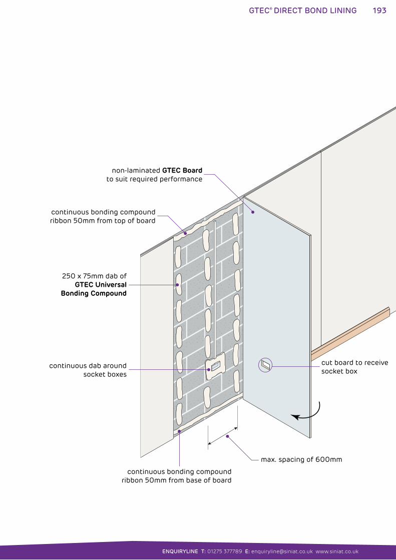
193
ENQUIRYLINE T: 01275 377789 E: [email protected] www.siniat.co.uk
GTEC® DIRECT BOND LINING
non-laminated GTEC Boardto suit required performance
cut board to receive socket box
max. spacing of 600mm
continuous dab around socket boxes
continuous bonding compoundribbon 50mm from base of board
250 x 75mm dab ofGTEC Universal
Bonding Compound
continuous bonding compoundribbon 50mm from top of board
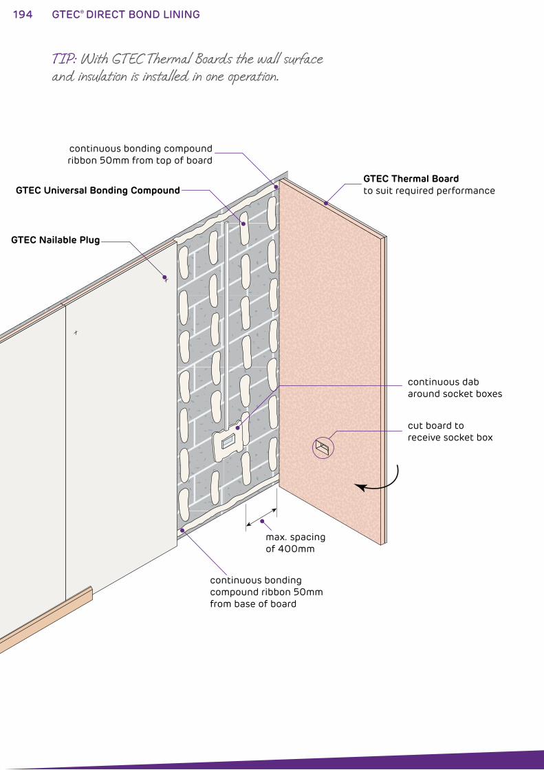
194 GTEC® DIRECT BOND LINING
GTEC Thermal Boardto suit required performance
cut board to receive socket box
max. spacing of 400mm
continuous bondingcompound ribbon 50mmfrom base of board
continuous bonding compoundribbon 50mm from top of board
GTEC Universal Bonding Compound
GTEC Nailable Plug
continuous dab around socket boxes
TIP: With GTEC Thermal Boards the wall surface and insulation is installed in one operation.
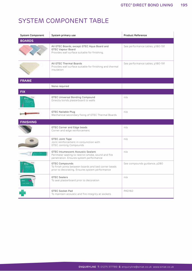
195
ENQUIRYLINE T: 01275 377789 E: [email protected] www.siniat.co.uk
GTEC® DIRECT BOND LINING
System Component System primary use Product Reference
BOARDS
All GTEC Boards, except GTEC Aqua Board and
GTEC Vapour Board
Provides wall surface suitable for finishing.
See performance tables, p180-191
All GTEC Thermal Boards
Provides wall surface suitable for finishing and thermal
insulation
See performance tables, p180-191
FRAME
None required
FIX
GTEC Universal Bonding Compound
Directly bonds plasterboard to walls
n/a
GTEC Nailable Plug
Mechanical secondary fixing of GTEC Thermal Boards
n/a
FINISHING
GTEC Corner and Edge beads
Corner and edge reinforcement
n/a
GTEC Joint Tape
Joint reinforcement in conjunction with
GTEC Jointing Compounds
n/a
GTEC Intumescent Acoustic Sealant
Perimeter sealing to restrict smoke, sound and fire
penetration. Ensures system performance
n/a
GTEC Compounds
To finish joints between boards and bed corner beads
prior to decorating. Ensures system performance
See compounds guidance, p280
GTEC Sealers
To seal plasterboard prior to decoration
n/a
GTEC Socket Pad
To maintain acoustic and fire integrity at sockets
PAD1&2
SYSTEM COMPONENT TABLE
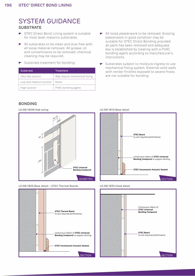
196 GTEC® DIRECT BOND LINING
50-75
25
50
250
GTEC UniversalBonding Compound
GTEC Boardto suit required performance
continuous ribbon of GTEC UniversalBonding Compound to support skirting
GTEC Intumescent Acoustic Sealant
LG-DB-180M-Dab sizing
GTEC Thermal Boardto suit required performance
continuous ribbon of GTEC UniversalBonding Compound to support skirting
GTEC Intumescent Acoustic Sealant
LG-DB-182S-Base detail – GTEC Thermal Boards
Continuous ribbon ofGTEC UniversalBonding Compound
GTEC Boardto suit required performance
LG-DB-183S-Head detail
LG-DB-181S-Base detail
SECTION SECTION
SECTION
SYSTEM GUIDANCESUBSTRATE
GTEC Direct Bond Lining system is suitable
for most level, masonry substrates.
All substrates to be clean and dust free with
all loose material removed. All grease, oil
and contaminants to be removed; chemical
cleaning may be required.
Substrate treatment for bonding:
All loose plasterwork to be removed. Existing
plasterwork in good condition may be
suitable for GTEC Direct Bonding provided
all paint has been removed and adequate
key is established by treating with a PVAC
bonding agent according to manufacturer’s
instructions.
Substrates subject to moisture ingress to use
mechanical fixing system. External solid walls
with render finishes exposed to severe frosts
are not suitable for bonding.
Substrate Treatment
Very low suction May require mechanical fixing
Low and medium suction None
High suction PVAC bonding agent
BONDING
ISOMETRIC
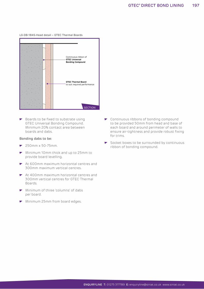
197
ENQUIRYLINE T: 01275 377789 E: [email protected] www.siniat.co.uk
GTEC® DIRECT BOND LINING
GTEC Thermal Boardto suit required performance
SECTION
Continuous ribbon ofGTEC UniversalBonding Compound
LG-DB-184S-Head detail – GTEC Thermal Boards
SECTION
Boards to be fixed to substrate using
GTEC Universal Bonding Compound.
Minimum 20% contact area between
boards and dabs.
Bonding dabs to be:
250mm x 50-75mm.
Minimum 10mm thick and up to 25mm to
provide board levelling.
At 600mm maximum horizontal centres and
300mm maximum vertical centres.
At 400mm maximum horizontal centres and
300mm vertical centres for GTEC Thermal
Boards.
Minimum of three ‘columns’ of dabs
per board.
Minimum 25mm from board edges.
Continuous ribbons of bonding compound
to be provided 50mm from head and base of
each board and around perimeter of walls to
ensure air-tightness and provide robust fixing
for trims.
Socket boxes to be surrounded by continuous
ribbon of bonding compound.
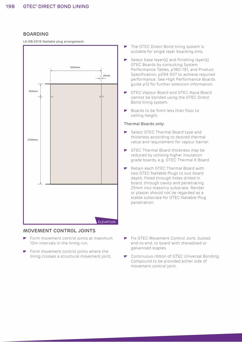
198 GTEC® DIRECT BOND LINING
300mm
1200mm
25mm
2100mm
LG-DB-201E-Nailable plug arrangement
BOARDING
ELEVATION
The GTEC Direct Bond lining system is
suitable for single layer boarding only.
Select base layer(s) and finishing layer(s)
GTEC Boards by consulting System
Performance Tables, p180-191, and Product
Specification, p294-307 to achieve required
performance. See High Performance Boards
guide p12 for further selection information.
GTEC Vapour Board and GTEC Aqua Board
cannot be bonded using the GTEC Direct
Bond lining system.
Boards to be 5mm less than floor to
ceiling height.
Thermal Boards only:
Select GTEC Thermal Board type and
thickness according to desired thermal
value and requirement for vapour barrier.
GTEC Thermal Board thickness may be
reduced by utilising higher insulation
grade boards, e.g. GTEC Thermal K Board.
Retain each GTEC Thermal Board with
two GTEC Nailable Plugs to suit board
depth, fitted through holes drilled in
board, through cavity and penetrating
25mm into masonry substrate. Render
or plaster should not be regarded as a
stable substrate for GTEC Nailable Plug
penetration.
MOVEMENT CONTROL JOINTS Form movement control joints at maximum
10m intervals in the lining run.
Form movement control joints where the
lining crosses a structural movement joint.
Fix GTEC Movement Control Joint, butted
end-to-end, to board with sheradised or
galvanised staples.
Continuous ribbon of GTEC Universal Bonding
Compound to be provided either side of
movement control joint.
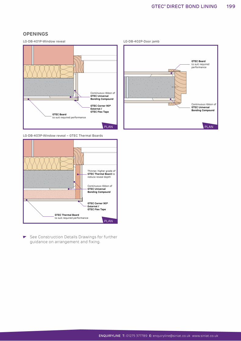
199
ENQUIRYLINE T: 01275 377789 E: [email protected] www.siniat.co.uk
GTEC® DIRECT BOND LINING
See Construction Details Drawings for further
guidance on arrangement and fixing.
GTEC Corner 90º External / GTEC Flex Tape
GTEC Boardto suit required performance
Continuous ribbon ofGTEC UniversalBonding Compound
Continuous ribbon ofGTEC UniversalBonding Compound
GTEC Boardto suit required performance
LG-DB-401P-Window reveal
GTEC Corner 90º External /GTEC Flex Tape
GTEC Thermal Boardto suit required performance
Thinner, higher grade of GTEC Thermal Board to reduce reveal depth
Continuous ribbon ofGTEC UniversalBonding Compound
LG-DB-403P-Window reveal – GTEC Thermal Boards
LG-DB-402P-Door jamb
OPENINGS
PLAN
PLAN
PLAN
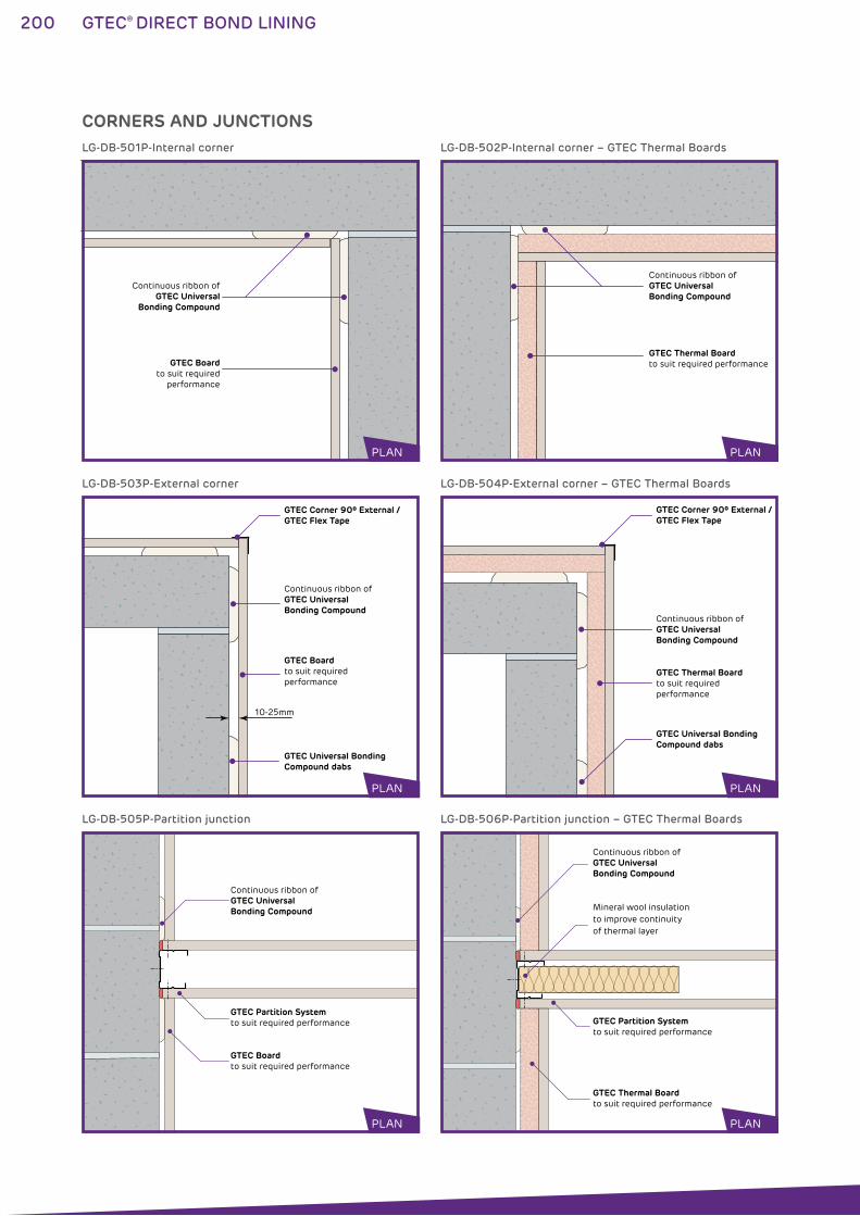
200 GTEC® DIRECT BOND LINING
GTEC Boardto suit required
performance
Continuous ribbon ofGTEC Universal
Bonding Compound
GTEC Thermal Boardto suit required performance
PLAN
Continuous ribbon ofGTEC UniversalBonding Compound
LG-DB-501P-Internal corner
10-25mm
GTEC Corner 90º External /GTEC Flex Tape
GTEC Universal Bonding Compound dabs
GTEC Boardto suit required performance
Continuous ribbon ofGTEC UniversalBonding Compound
LG-DB-503P-External corner
GTEC Boardto suit required performance
GTEC Partition Systemto suit required performance
Continuous ribbon ofGTEC UniversalBonding Compound
LG-DB-505P-Partition junction
GTEC Corner 90º External /GTEC Flex Tape
GTEC Universal Bonding Compound dabs
GTEC Thermal Boardto suit required performance
Continuous ribbon ofGTEC UniversalBonding Compound
LG-DB-504P-External corner – GTEC Thermal Boards
GTEC Partition Systemto suit required performance
Mineral wool insulation to improve continuity of thermal layer
GTEC Thermal Boardto suit required performance
Continuous ribbon ofGTEC UniversalBonding Compound
LG-DB-506P-Partition junction – GTEC Thermal Boards
LG-DB-502P-Internal corner – GTEC Thermal Boards
CORNERS AND JUNCTIONS
PLAN
PLAN PLAN
PLAN PLAN
PLAN
201
ENQUIRYLINE T: 01275 377789 E: [email protected] www.siniat.co.uk
GTEC® DIRECT BOND LINING
See Construction Details Drawings for further
guidance on arrangement and fixing.
FINISHING All board joints to be taped, jointed
or finished according to guidance in
Finishing section (p276-291) to achieve
system performances.
GTEC Finish materials appropriate to board
type to be used.
PENETRATIONS M&E runs and other services to be
pre-planned to minimise or eliminate
penetrations through rated linings.
Any penetrations must be fully sealed
with GTEC Intumescent Acoustic Sealant
or other fire resisting material as specified
in Construction Detail Drawings.
Protect all electrical cables in cavity
with conduit.
SYSTEM CONTINUITY Bead of GTEC Intumescent Acoustic Sealant
to be applied to perimeter of all runs and in
all other locations specified in Construction
Detail Drawings.
GTEC Intumescent Acoustic Sealant to seal
all other acoustic or air paths to prevent fire/
smoke spread and acoustic transmission.
Full, imperforate system continuity to be
maintained to achieve rated performances.
FIXTURES All fixtures to be fixed through to substrate
using appropriate fixings.
202 GTEC® CONTOUR LINING
GTEC® CONTOUR LINING SYSTEMSThe GTEC Contour Lining system is a simple and fast means
of renovating flat walls which simply need a new, consistently
smooth finish e.g. tiled or plastered walls which have become
scuffed or chipped.
The system uses GTEC Wall Lining Adhesive to directly attach
light and strong GTEC Contour Board to the substrate. It provides
a smooth surface by boarding over existing finishes but will not
correct substrates which are out of plumb.
Once complete, the system provides a smooth and easy to finish
plasterboard surface in the minimum thickness.
WHERE TO USE: GTEC Contour Board Lining system is suitable for use over
existing wall finishes such as distressed tiled walls.
FEATURES BENEFITS
8mm total lining thickness Minimum increase in wall thickness
Quick curing adhesive Can be jointed and finished quickly after
initial installation
High strength adhesive No need to remove firmly attached plasterwork
or tiling from the substrate
Lightweight board Easy to install
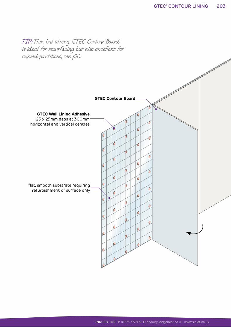
203
ENQUIRYLINE T: 01275 377789 E: [email protected] www.siniat.co.uk
GTEC® CONTOUR LINING
GTEC Contour Board
GTEC Wall Lining Adhesive25 x 25mm dabs at 300mm
horizontal and vertical centres
flat, smooth substrate requiring refurbishment of surface only
TIP: Thin, but strong, GTEC Contour Board is ideal for resurfacing but also excellent for curved partitions, see p70.
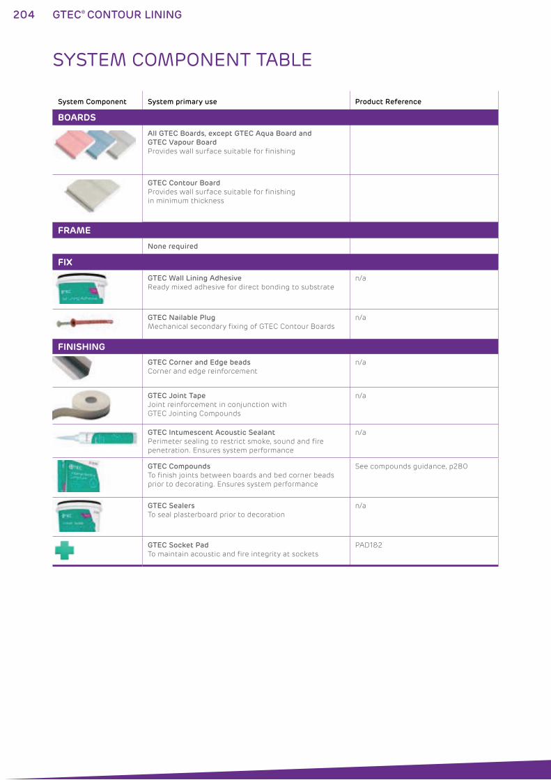
204 GTEC® CONTOUR LINING
System Component System primary use Product Reference
BOARDS
All GTEC Boards, except GTEC Aqua Board and
GTEC Vapour Board
Provides wall surface suitable for finishing
GTEC Contour Board
Provides wall surface suitable for finishing
in minimum thickness
FRAME
None required
FIX
GTEC Wall Lining Adhesive
Ready mixed adhesive for direct bonding to substrate
n/a
GTEC Nailable Plug
Mechanical secondary fixing of GTEC Contour Boards
n/a
FINISHING
GTEC Corner and Edge beads
Corner and edge reinforcement
n/a
GTEC Joint Tape
Joint reinforcement in conjunction with
GTEC Jointing Compounds
n/a
GTEC Intumescent Acoustic Sealant
Perimeter sealing to restrict smoke, sound and fire
penetration. Ensures system performance
n/a
GTEC Compounds
To finish joints between boards and bed corner beads
prior to decorating. Ensures system performance
See compounds guidance, p280
GTEC Sealers
To seal plasterboard prior to decoration
n/a
GTEC Socket Pad
To maintain acoustic and fire integrity at sockets
PAD1&2
SYSTEM COMPONENT TABLE
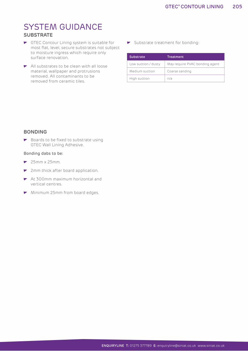
205
ENQUIRYLINE T: 01275 377789 E: [email protected] www.siniat.co.uk
GTEC® CONTOUR LINING
SYSTEM GUIDANCESUBSTRATE
GTEC Contour Lining system is suitable for
most flat, level, secure substrates not subject
to moisture ingress which require only
surface renovation.
All substrates to be clean with all loose
material, wallpaper and protrusions
removed. All contaminants to be
removed from ceramic tiles.
Substrate treatment for bonding:
Boards to be fixed to substrate using
GTEC Wall Lining Adhesive.
Bonding dabs to be:
25mm x 25mm.
2mm thick after board application.
At 300mm maximum horizontal and
vertical centres.
Minimum 25mm from board edges.
Substrate Treatment
Low suction / dusty May require PVAC bonding agent
Medium suction Coarse sanding
High suction n/a
BONDING
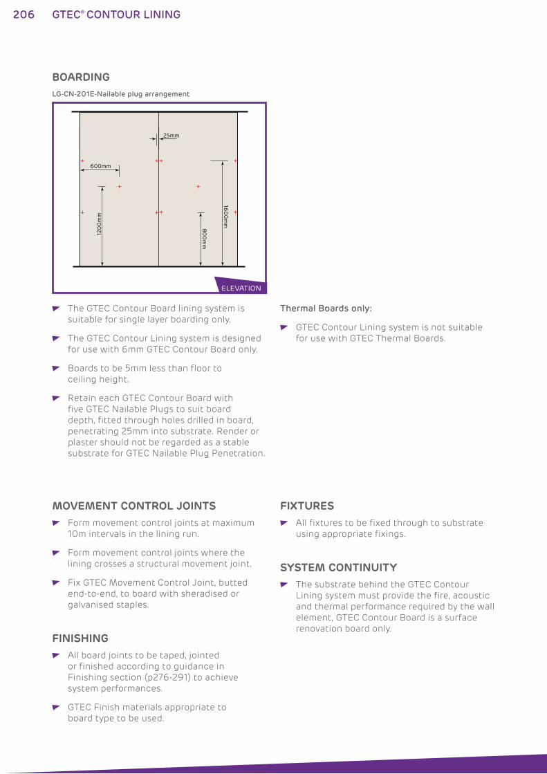
206 GTEC® CONTOUR LINING
600mm
25mm
120
0m
m
80
0m
m
160
0m
m
LG-CN-201E-Nailable plug arrangement
BOARDING
The GTEC Contour Board lining system is
suitable for single layer boarding only.
The GTEC Contour Lining system is designed
for use with 6mm GTEC Contour Board only.
Boards to be 5mm less than floor to
ceiling height.
Retain each GTEC Contour Board with
five GTEC Nailable Plugs to suit board
depth, fitted through holes drilled in board,
penetrating 25mm into substrate. Render or
plaster should not be regarded as a stable
substrate for GTEC Nailable Plug Penetration.
Thermal Boards only:
GTEC Contour Lining system is not suitable
for use with GTEC Thermal Boards.
ELEVATION
MOVEMENT CONTROL JOINTS Form movement control joints at maximum
10m intervals in the lining run.
Form movement control joints where the
lining crosses a structural movement joint.
Fix GTEC Movement Control Joint, butted
end-to-end, to board with sheradised or
galvanised staples.
FINISHING All board joints to be taped, jointed
or finished according to guidance in
Finishing section (p276-291) to achieve
system performances.
GTEC Finish materials appropriate to
board type to be used.
SYSTEM CONTINUITY The substrate behind the GTEC Contour
Lining system must provide the fire, acoustic
and thermal performance required by the wall
element, GTEC Contour Board is a surface
renovation board only.
FIXTURES All fixtures to be fixed through to substrate
using appropriate fixings.
208 GTEC® SHALLOW WALL LINING
GTEC® SHALLOW WALL LINING SYSTEMSThe GTEC Shallow Wall Lining system is an alternative to the
GTEC Direct Bond Lining system. It provides a mechanical fix for
boards which are unsuitable for use with GTEC Universal Bonding
Compound. It can also create a fully mechanically fixed option where
the substrate cannot be bonded, such as some concrete walls.
The system uses GTEC Universal Bonding Compound to attach
GTEC Shallow Wall Channels to the substrate providing a fixing
surface for GTEC Boards. When bonded, it can correct minor surface
irregularities through minimal levelling adjustment of the shallow
channel before the dabs have cured. Alternatively, the GTEC Shallow
Wall Channels can be fixed directly into the substrate.
WHERE TO USE: The GTEC Shallow Wall Lining system is suitable for most project
types and masonry substrates.
FEATURES BENEFITS
Plasterboard finish Easy to decorate flat surface
Intermittent cavity up to 25mm deep Space for small conduits and services
Mechanical board fixing Substrate for all GTEC Boards
Mechanical or adhesive channel fixing Fixes to most substrates
Compatible with GTEC Thermal Boards Improves U-values
Perforated channel for bonding key Strong and easy to fix
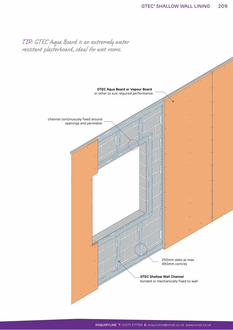
209
ENQUIRYLINE T: 01275 377789 E: [email protected] www.siniat.co.uk
GTEC® SHALLOW WALL LINING
250mm dabs at max. 450mm centres
GTEC Aqua Board or Vapour Board or other to suit required performance
GTEC Shallow Wall Channelbonded or mechanically fixed to wall
channel continuously fixed around openings and perimeter
TIP: GTEC Aqua Board is an extremely water resistant plasterboard, ideal for wet rooms.
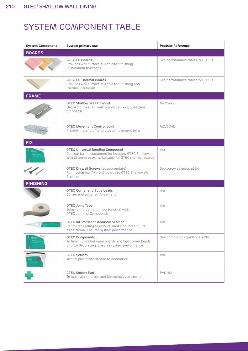
210 GTEC® SHALLOW WALL LINING
System Component System primary use Product Reference
BOARDS
All GTEC Boards
Provides wall surface suitable for finishing
in minimum thickness
See performance tables, p180-191
All GTEC Thermal Boards
Provides wall surface suitable for finishing and
thermal insulation
See performance tables, p180-191
FRAME
GTEC Shallow Wall Channel
Dabbed or fixed to wall to provide fixing substrate
for boards
MFCS/RX
GTEC Movement Control Joint
Flexible metal profile to create movement joint
MCJ304D
FIX
GTEC Universal Bonding Compound
Gypsum based compound for bonding GTEC Shallow
Wall Channel to walls. Suitable for GTEC thermal boards
n/a
GTEC Drywall Screws (as appropriate)
For mechanical fixing of boards to GTEC Shallow Wall
Channel
See screw selector, p334
FINISHING
GTEC Corner and Edge beads
Corner and edge reinforcement
n/a
GTEC Joint Tape
Joint reinforcement in conjunction with
GTEC Jointing Compounds
n/a
GTEC Intumescent Acoustic Sealant
Perimeter sealing to restrict smoke, sound and fire
penetration. Ensures system performance
n/a
GTEC Compounds
To finish joints between boards and bed corner beads
prior to decorating. Ensures system performance
See compounds guidance, p280
GTEC Sealers
To seal plasterboard prior to decoration
n/a
GTEC Socket Pad
To maintain acoustic and fire integrity at sockets
PAD1&2
SYSTEM COMPONENT TABLE
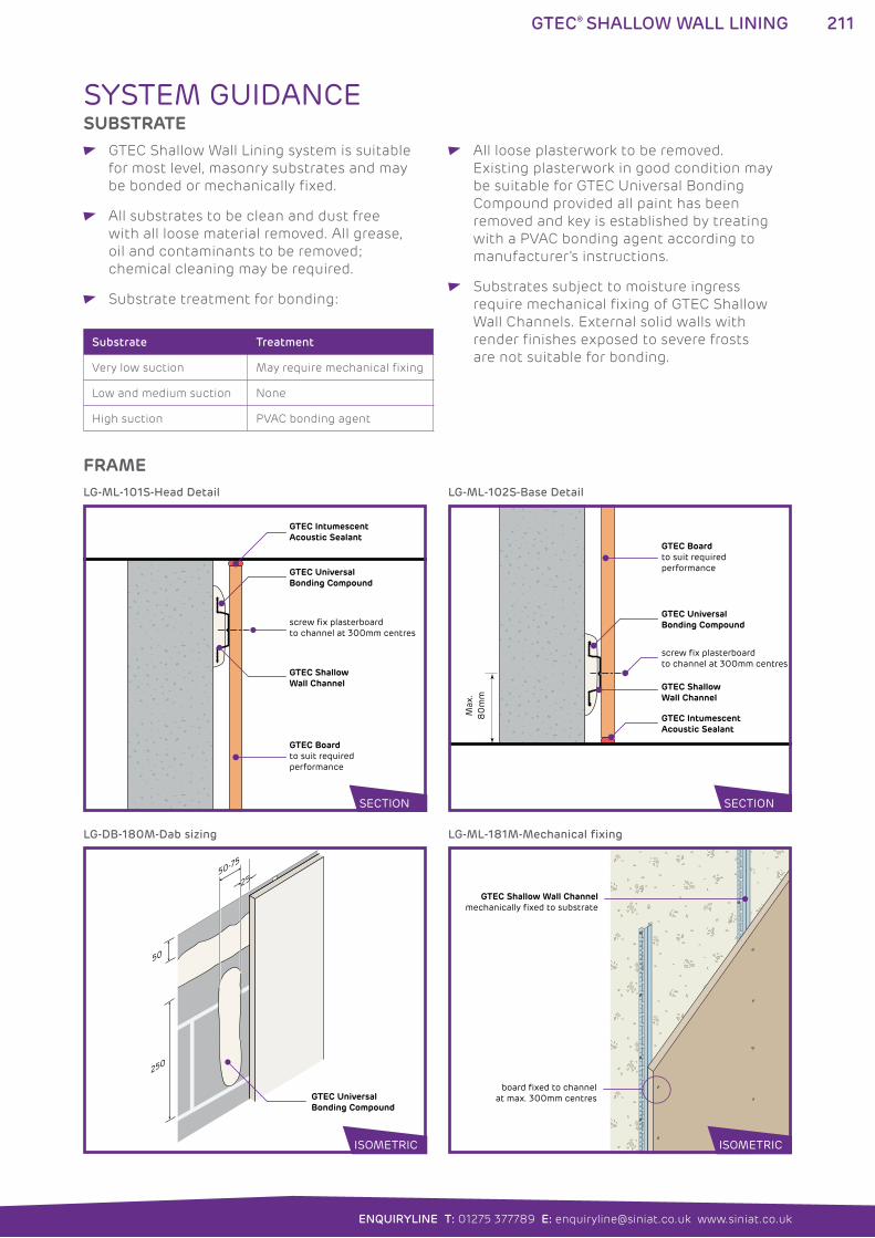
211
ENQUIRYLINE T: 01275 377789 E: [email protected] www.siniat.co.uk
GTEC® SHALLOW WALL LINING
SYSTEM GUIDANCESUBSTRATE
GTEC Shallow Wall Lining system is suitable
for most level, masonry substrates and may
be bonded or mechanically fixed.
All substrates to be clean and dust free
with all loose material removed. All grease,
oil and contaminants to be removed;
chemical cleaning may be required.
Substrate treatment for bonding:
All loose plasterwork to be removed.
Existing plasterwork in good condition may
be suitable for GTEC Universal Bonding
Compound provided all paint has been
removed and key is established by treating
with a PVAC bonding agent according to
manufacturer’s instructions.
Substrates subject to moisture ingress
require mechanical fixing of GTEC Shallow
Wall Channels. External solid walls with
render finishes exposed to severe frosts
are not suitable for bonding.Substrate Treatment
Very low suction May require mechanical fixing
Low and medium suction None
High suction PVAC bonding agent
GTEC Intumescent Acoustic Sealant
GTEC Boardto suit required performance
GTEC Shallow Wall Channel
GTEC UniversalBonding Compound
screw fix plasterboard to channel at 300mm centres
Max
.8
0m
m
GTEC Intumescent Acoustic Sealant
GTEC Boardto suit required performance
GTEC Shallow Wall Channel
GTEC UniversalBonding Compound
screw fix plasterboard to channel at 300mm centres
LG-ML-101S-Head Detail
50-75
25
50
250
GTEC UniversalBonding Compound
LG-DB-180M-Dab sizing
GTEC Shallow Wall Channelmechanically fixed to substrate
board fixed to channel at max. 300mm centres
LG-ML-181M-Mechanical fixing
LG-ML-102S-Base Detail
FRAME
SECTION SECTION
ISOMETRIC ISOMETRIC
212 GTEC® SHALLOW WALL LINING
GTEC Shallow Wall Channel to be fixed to
substrate in continuous vertical lengths
at 600mm horizontal centres using dabs
of GTEC Universal Bonding Compound or
mechanically fixed using appropriate fixings
by others.
GTEC Shallow Wall Channels may be shot
fired to dense substrates following fixing
manufacturer’s instructions.
Horizontal lengths of GTEC Shallow Wall
Channel to be fixed maximum 50mm from
head and base of lining.
Bonding dabs to be:
250mm x 50-75mm.
Minimum 10mm thick and up to 25mm
to provide board levelling.
At 450mm maximum vertical centres.
Minimum of two dabs per channel not
exceeding vertical centres above.
Minimum 25mm from board edges.
Continuous ribbons of bonding
compound to be provided 50mm from
head and base of board and around
perimeter of walls and openings to
provide fixing for horizontal channel.
Socket boxes to be surrounded by continuous
ribbon of bonding compound.
The GTEC Shallow Wall lining system is
suitable for single layer boarding only.
Select base layer(s) and finishing layer(s)
GTEC Boards by consulting System
Performance Tables, p180-191, and Product
Specification, p294-307, to achieve required
performance. See High Performance Boards
guide p12 for further selection information.
Boards to be 5mm less than floor to
ceiling height.
Board edges to be centred over channels.
Boards to be mechanically fixed to channels
at 300mm centres using appropriate GTEC
Drywall Screws. See screw selector p334.
Height of GTEC Shallow Wall linings should
not exceed two boards in height in one
operation. Safety precautions should be
taken when bonding boards above single
board height.
Thermal Boards only:
Select GTEC Thermal Board type and
thickness according to desired thermal value
and requirement for vapour barrier.
GTEC Thermal Board thickness may be
reduced by utilising higher insulation grade
boards, e.g. GTEC Thermal K Board.
BOARDING
FRAME continued
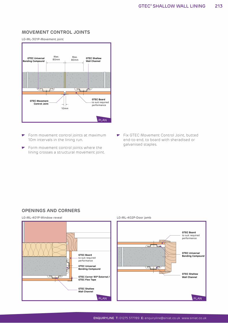
213
ENQUIRYLINE T: 01275 377789 E: [email protected] www.siniat.co.uk
GTEC® SHALLOW WALL LINING
Form movement control joints at maximum
10m intervals in the lining run.
Form movement control joints where the
lining crosses a structural movement joint.
Fix GTEC Movement Control Joint, butted
end-to-end, to board with sheradised or
galvanised staples.
Max. 80mm
Max. 80mm
10mm
GTEC UniversalBonding Compound
GTEC Boardto suit required performance
GTEC MovementControl Joint
GTEC Shallow Wall Channel
GTEC Corner 90º External /GTEC Flex Tape
GTEC Boardto suit required performance
GTEC Shallow Wall Channel
GTEC UniversalBonding Compound
GTEC UniversalBonding Compound
GTEC Boardto suit requiredperformance
GTEC Shallow Wall Channel
LG-ML-301P-Movement joint
LG-ML-401P-Window reveal LG-ML-402P-Door jamb
MOVEMENT CONTROL JOINTS
OPENINGS AND CORNERS
PLAN
PLAN PLAN
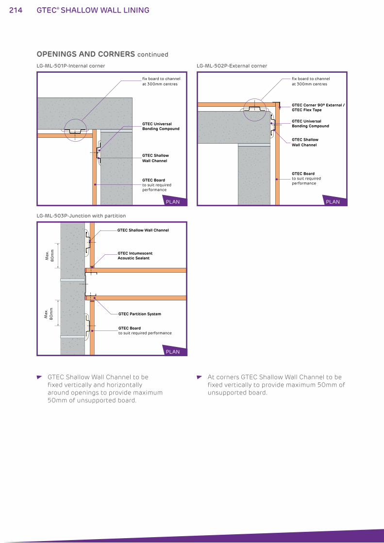
214 GTEC® SHALLOW WALL LINING
OPENINGS AND CORNERS continued
GTEC ShallowWall Channel
GTEC Boardto suit required performance
fix board to channel at 300mm centres
GTEC UniversalBonding Compound
GTEC Intumescent Acoustic Sealant
GTEC Boardto suit required performance
GTEC Partition System
Max
.8
0m
m
Max
.8
0m
m
GTEC Shallow Wall Channel
GTEC Corner 90º External /GTEC Flex Tape
GTEC Boardto suit requiredperformance
fix board to channel at 300mm centres
GTEC Shallow Wall Channel
GTEC UniversalBonding Compound
LG-ML-501P-Internal corner
LG-ML-503P-Junction with partition
LG-ML-502P-External corner
PLAN
PLAN
PLAN
GTEC Shallow Wall Channel to be
fixed vertically and horizontally
around openings to provide maximum
50mm of unsupported board.
At corners GTEC Shallow Wall Channel to be
fixed vertically to provide maximum 50mm of
unsupported board.
215
ENQUIRYLINE T: 01275 377789 E: [email protected] www.siniat.co.uk
GTEC® SHALLOW WALL LINING
FINISHING All board joints to be taped, jointed
or finished according to guidance
in Finishing section (p276-291) to achieve
system performances.
GTEC Finish materials appropriate to board
type to be used
PENETRATIONS M&E runs and other services to be
pre-planned to minimise or eliminate
penetrations through rated linings.
Any penetrations must be fully sealed
with GTEC Intumescent Acoustic Sealant
or other fire resisting material as specified
in Construction Detail Drawings.
Protect all electrical cables in cavity
with conduit.
SYSTEM CONTINUITY Bead of GTEC Intumescent Acoustic Sealant
to be applied to perimeter of all runs and in
all other locations specified in Construction
Detail Drawings.
GTEC Intumescent Acoustic Sealant to seal
all other acoustic or air paths to prevent fire/
smoke spread and acoustic transmission.
Full, imperforate system continuity to be
maintained to achieve rated performances.
Where channels are mechanically
fixed there are no inherent restrictions
on height providing board loads are
fully transferred to substrate.
FIXTURES All fixtures to be fixed through to substrate
using appropriate fixings.
216 GTEC® DRYLINER LINING
GTEC® DRYLINER LINING SYSTEMSThe GTEC Dryliner Lining system is a fully dry, light frame,
drylining system. The cavity created behind the boards allows
for heavier services and sound or thermal insulation.
For stable, high performance drylining, the system uses GTEC Dryliner
Brackets fixed to the substrate to support a frame of GTEC Dryliner
Channel and Tracks.
Once complete, the GTEC Dryliner Lining system provides a clean,
flat and easy to finish plasterboard surface with superior technical
performance than shallow lining systems.
WHERE TO USE: The GTEC Dryliner Lining system is ideal for most stable
substrates where continuous cavities behind boards of up
to 130mm are required and/or where high levels of substrate
correction are needed.
FEATURES BENEFITS
Plasterboard finish Easy to decorate flat surface
Cavity up to 130mm deep Space for heavy duty services and insulation
Mechanical fixing board Fixes all GTEC Boards
Cavity frame design Achieves higher technical performances
Mechanical fixing bracket Fixes to most stable substrates
Compatible with GTEC Thermal Boards Improves U-values
Adjustable bracket design Can adjust depth for high level of
substrate correction
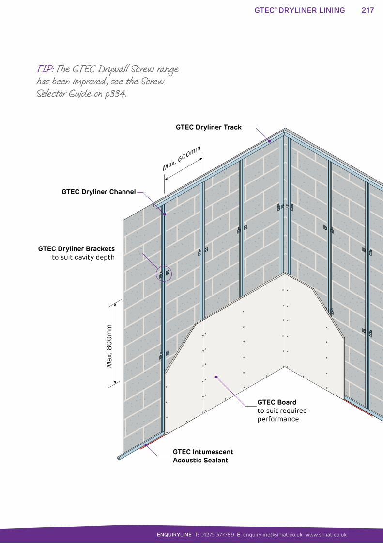
217
ENQUIRYLINE T: 01275 377789 E: [email protected] www.siniat.co.uk
GTEC® DRYLINER LINING
GTEC Dryliner Track
GTEC Dryliner Channel
GTEC Dryliner Bracketsto suit cavity depth
GTEC Boardto suit required performance
GTEC Intumescent Acoustic Sealant
Max. 600mm
Max
. 80
0m
m
TIP: The GTEC Drywall Screw range has been improved, see the Screw Selector Guide on p334.
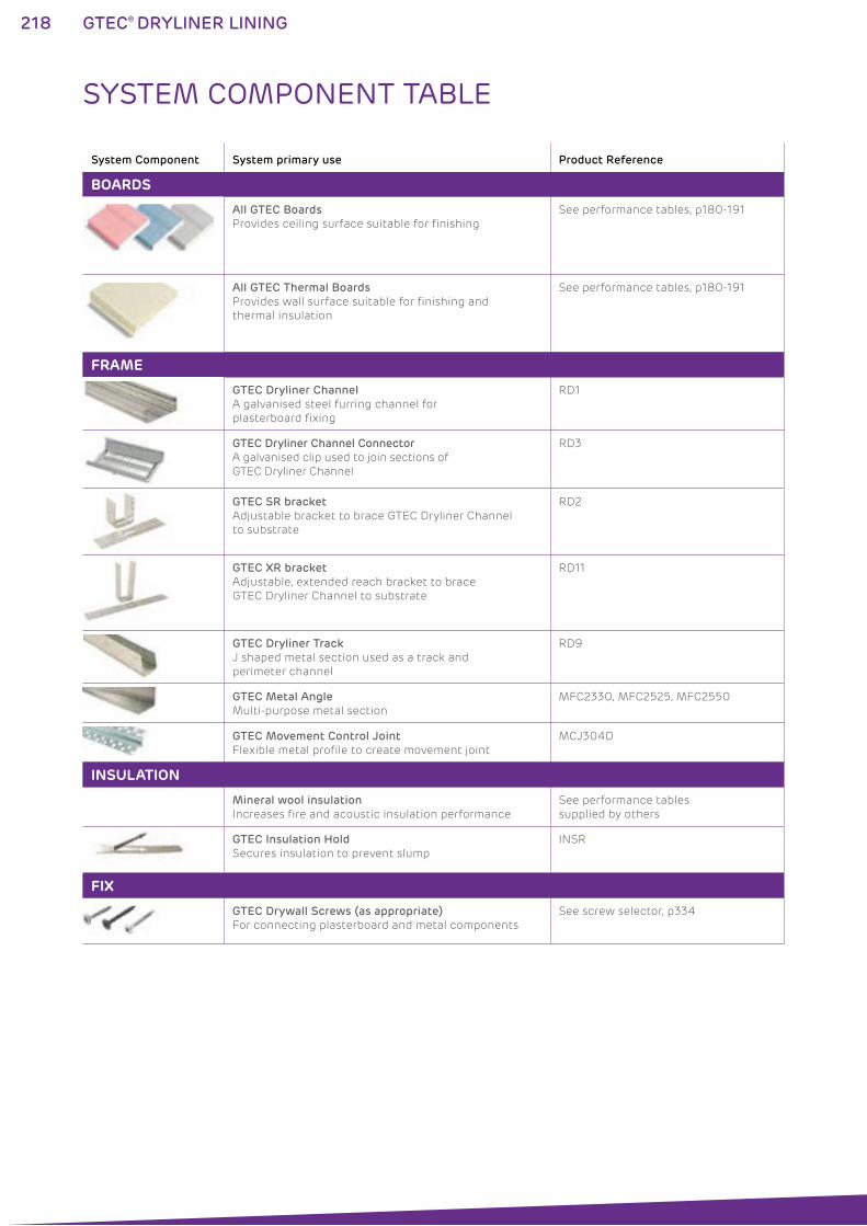
218 GTEC® DRYLINER LINING
System Component System primary use Product Reference
BOARDS
All GTEC Boards
Provides ceiling surface suitable for finishing
See performance tables, p180-191
All GTEC Thermal Boards
Provides wall surface suitable for finishing and
thermal insulation
See performance tables, p180-191
FRAME
GTEC Dryliner Channel
A galvanised steel furring channel for
plasterboard fixing
RD1
GTEC Dryliner Channel Connector
A galvanised clip used to join sections of
GTEC Dryliner Channel
RD3
GTEC SR bracket
Adjustable bracket to brace GTEC Dryliner Channel
to substrate
RD2
GTEC XR bracket
Adjustable, extended reach bracket to brace
GTEC Dryliner Channel to substrate
RD11
GTEC Dryliner Track
J shaped metal section used as a track and
perimeter channel
RD9
GTEC Metal Angle
Multi-purpose metal section
MFC2330, MFC2525, MFC2550
GTEC Movement Control Joint
Flexible metal profile to create movement joint
MCJ304D
INSULATION
Mineral wool insulation
Increases fire and acoustic insulation performance
See performance tables
supplied by others
GTEC Insulation Hold
Secures insulation to prevent slump
INSR
FIX
GTEC Drywall Screws (as appropriate)
For connecting plasterboard and metal components
See screw selector, p334
SYSTEM COMPONENT TABLE
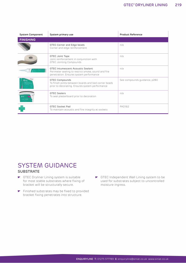
219
ENQUIRYLINE T: 01275 377789 E: [email protected] www.siniat.co.uk
GTEC® DRYLINER LINING
System Component System primary use Product Reference
FINISHING
GTEC Corner and Edge beads
Corner and edge reinforcement
n/a
GTEC Joint Tape
Joint reinforcement in conjunction with
GTEC Jointing Compounds
n/a
GTEC Intumescent Acoustic Sealant
Perimeter sealing to restrict smoke, sound and fire
penetration. Ensures system performance
n/a
GTEC Compounds
To finish joints between boards and bed corner beads
prior to decorating. Ensures system performance
See compounds guidance, p280
GTEC Sealers
To seal plasterboard prior to decoration
n/a
GTEC Socket Pad
To maintain acoustic and fire integrity at sockets
PAD1&2
SYSTEM GUIDANCESUBSTRATE
GTEC Dryliner Lining system is suitable
for most stable substrates where fixing of
bracket will be structurally secure.
Finished substrates may be fixed to provided
bracket fixing penetrates into structure.
GTEC Independent Wall Lining system to be
used for substrates subject to uncontrolled
moisture ingress.
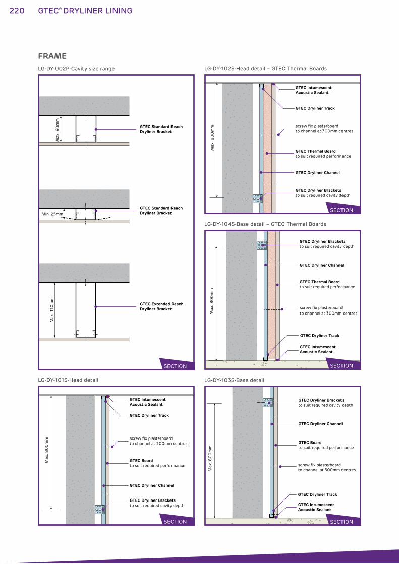
220 GTEC® DRYLINER LINING
Max
. 60
mm
Min. 25mm
Max
. 130
mm
GTEC Standard Reach Dryliner Bracket
GTEC Standard Reach Dryliner Bracket
GTEC Extended Reach Dryliner Bracket
GTEC Dryliner Track
GTEC Dryliner Channel
GTEC Dryliner Bracketsto suit required cavity depth
GTEC Boardto suit required performance
GTEC Intumescent Acoustic Sealant
Max
. 80
0m
m screw fix plasterboard to channel at 300mm centres
GTEC Dryliner Track
GTEC Dryliner Channel
GTEC Dryliner Bracketsto suit required cavity depth
GTEC Thermal Boardto suit required performance
GTEC Intumescent Acoustic Sealant
Max
. 80
0m
m screw fix plasterboard to channel at 300mm centres
GTEC Dryliner Track
GTEC Dryliner Channel
GTEC Dryliner Bracketsto suit required cavity depth
GTEC Boardto suit required performance
GTEC Intumescent Acoustic Sealant
Max
. 80
0m
m
screw fix plasterboard to channel at 300mm centres
GTEC Dryliner Track
GTEC Dryliner Channel
GTEC Dryliner Bracketsto suit required cavity depth
GTEC Thermal Boardto suit required performance
GTEC Intumescent Acoustic Sealant
Max
. 80
0m
m
screw fix plasterboard to channel at 300mm centres
LG-DY-002P-Cavity size range
LG-DY-101S-Head detail
LG-DY-102S-Head detail – GTEC Thermal Boards
LG-DY-103S-Base detail
LG-DY-104S-Base detail – GTEC Thermal Boards
FRAME
SECTION
SECTION
SECTION
SECTION
SECTION
221
ENQUIRYLINE T: 01275 377789 E: [email protected] www.siniat.co.uk
GTEC® DRYLINER LINING
GTEC Dryliner Track to be fixed to structure
at perimeter of lining run. Fix at 600mm
centres using appropriate fixings. Allow for
board depth when positioning channel and
to achieve required cavity depth.
Select GTEC Dryliner Brackets (SR and XR)
to suit cavity depth required:
GTEC Dryliner Bracket Cavity Depth Range
GTEC SR Bracket 25mm-60mm
GTEC XR Bracket 25mm-130mm
GTEC Dryliner Channel to be positioned at
maximum 600mm centres for GTEC Board
and at maximum 400mm horizontal centres
for GTEC Thermal Boards.
GTEC Dryliner Brackets to fixed to structure
in a line at maximum 800mm vertical centres
to receive GTEC Dryliner Channel:
GTEC SR and XR Brackets to be fixed
using appropriate structural fixing
supplied by others.
GTEC Dryliner Channel to be 5mm shorter
than floor to ceiling height, located into
GTEC Dryliner Track.
GTEC Dryliner Channel to be attached to both
GTEC Dryliner Bracket legs with appropriate
GTEC Drywall Screws (see screw selector
p334) and levelled by adjusting brackets.
Excess bracket leg length to be removed or
bent back.
GTEC Dryliner Channel may be spliced if
necessary using GTEC Dryliner Channel
Connector.
INSULATION Any insulation to be of type and thickness
to achieve performance and tightly installed
in a continuous layer between brackets and
behind channels.
Where insulation may be expected to slump
suspend from GTEC Insulation Hold strips
150mm from top of partition and at 1200mm
vertical centres.
10mm clear gap to be maintained between
substrate and insulation.
BOARDING The GTEC Dryliner lining system is suitable for
single, double and multiple layer boarding.
Select base layer(s) and finishing layer(s)
GTEC Boards by consulting System
Performance Tables, p180-191, and Product
Specification, p294-307, to achieve required
performance. See High Performance Boards
guide p12 for further selection information.
Boards to be 5mm less than floor to
ceiling height.
Board edges to be centred over channels.
Boards to be mechanically fixed to channels
and track at 300mm centres using
appropriate GTEC Drywall Screws.
See screw selector p334.
Board joints to be staggered between layers.
Over-height single layer boarding:
Where partition height exceeds board height
fix boards to continuous band of GTEC Flat
Strap FS90/W or GTEC MFIX behind all
horizontal joints to maintain fire integrity.
Over-height multiple layer boarding only:
Where partition height exceeds board
height for double or multiple layer boarding
fix outer layer of boards to continuous
band of GTEC Flat Strap FS50/RX behind
all horizontal joints.
Thermal Boards only:
Select GTEC Thermal Board type and
thickness according to desired thermal
value and requirement for vapour barrier.
GTEC Thermal Board thickness may be
reduced by utilising higher insulation
grade boards, e.g. GTEC Thermal K Board.
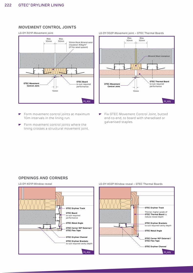
222 GTEC® DRYLINER LINING
Form movement control joints at maximum
10m intervals in the lining run.
Form movement control joints where the
lining crosses a structural movement joint.
Fix GTEC Movement Control Joint, butted
end-to-end, to board with sheradised or
galvanised staples.
MOVEMENT CONTROL JOINTS
OPENINGS AND CORNERS
50mm Rock Mineral wool insulation 40kg/m3 (if fire rated system)
Max. 50mm
Max. 50mm
10mm
GTEC Boardto suit required performance
GTEC MovementControl Joint
GTEC Dryliner Channel
GTEC Corner 90º External /GTEC Flex Tape
GTEC Metal Angle
GTEC Dryliner Bracketsto suit required cavity depth
GTEC Boardto suit required performance
GTEC Dryliner Track
Max. 50mm
Max. 50mm
10mm
GTEC MovementControl Joint
GTEC Thermal Boardto suit required performance
Mineral Wool insulation
GTEC Dryliner Channel
GTEC Corner 90º External /GTEC Flex Tape
GTEC Metal Angle
GTEC Dryliner Bracketsto suit required cavity depth
GTEC Dryliner Track
Thinner, higher grade of GTEC Thermal Board to reduce reveal depth
LG-DY-301P-Movement joint
LG-DY-401P-Window reveal
LG-DY-302P-Movement joint – GTEC Thermal Boards
LG-DY-402P-Window reveal – GTEC Thermal Boards
PLAN
PLAN
PLAN
PLAN
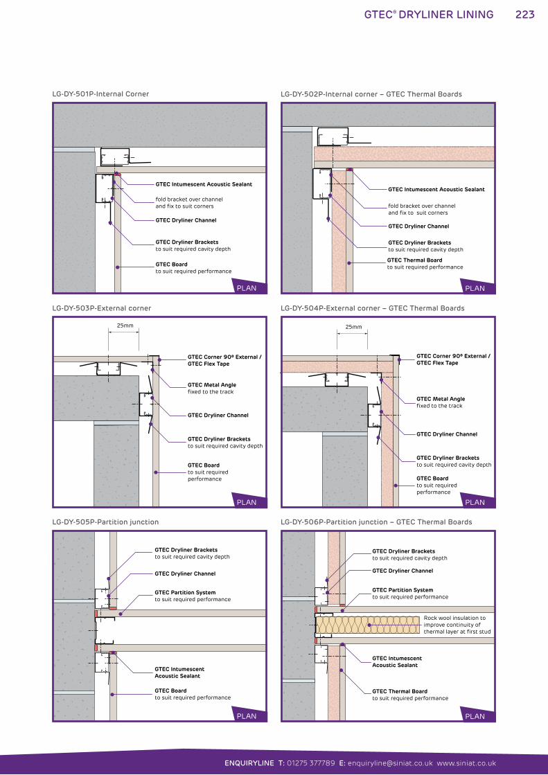
223
ENQUIRYLINE T: 01275 377789 E: [email protected] www.siniat.co.uk
GTEC® DRYLINER LINING
GTEC Intumescent Acoustic Sealant
GTEC Dryliner Channel
GTEC Dryliner Bracketsto suit required cavity depth
fold bracket over channel and fix to suit corners
GTEC Boardto suit required performance
GTEC Intumescent Acoustic Sealant
GTEC Dryliner Channel
GTEC Dryliner Bracketsto suit required cavity depth
GTEC Thermal Boardto suit required performance
fold bracket over channel and fix to suit corners
LG-DY-501P-Internal Corner LG-DY-502P-Internal corner – GTEC Thermal Boards
PLAN PLAN
GTEC Dryliner Channel
GTEC Dryliner Bracketsto suit required cavity depth
GTEC Boardto suit required performance
GTEC Corner 90º External /GTEC Flex Tape
GTEC Metal Anglefixed to the track
25mm
GTEC Intumescent Acoustic Sealant
GTEC Boardto suit required performance
GTEC Partition Systemto suit required performance
GTEC Dryliner Bracketsto suit required cavity depth
GTEC Dryliner Channel
GTEC Dryliner Channel
GTEC Dryliner Bracketsto suit required cavity depth
GTEC Boardto suit required performance
GTEC Corner 90º External /GTEC Flex Tape
GTEC Metal Angle fixed to the track
25mm
GTEC Intumescent Acoustic Sealant
GTEC Thermal Boardto suit required performance
GTEC Partition Systemto suit required performance
GTEC Dryliner Bracketsto suit required cavity depth
GTEC Dryliner Channel
Rock wool insulation toimprove continuity of thermal layer at first stud
LG-DY-503P-External corner
LG-DY-505P-Partition junction
LG-DY-504P-External corner – GTEC Thermal Boards
LG-DY-506P-Partition junction – GTEC Thermal Boards
PLAN
PLAN
PLAN
PLAN
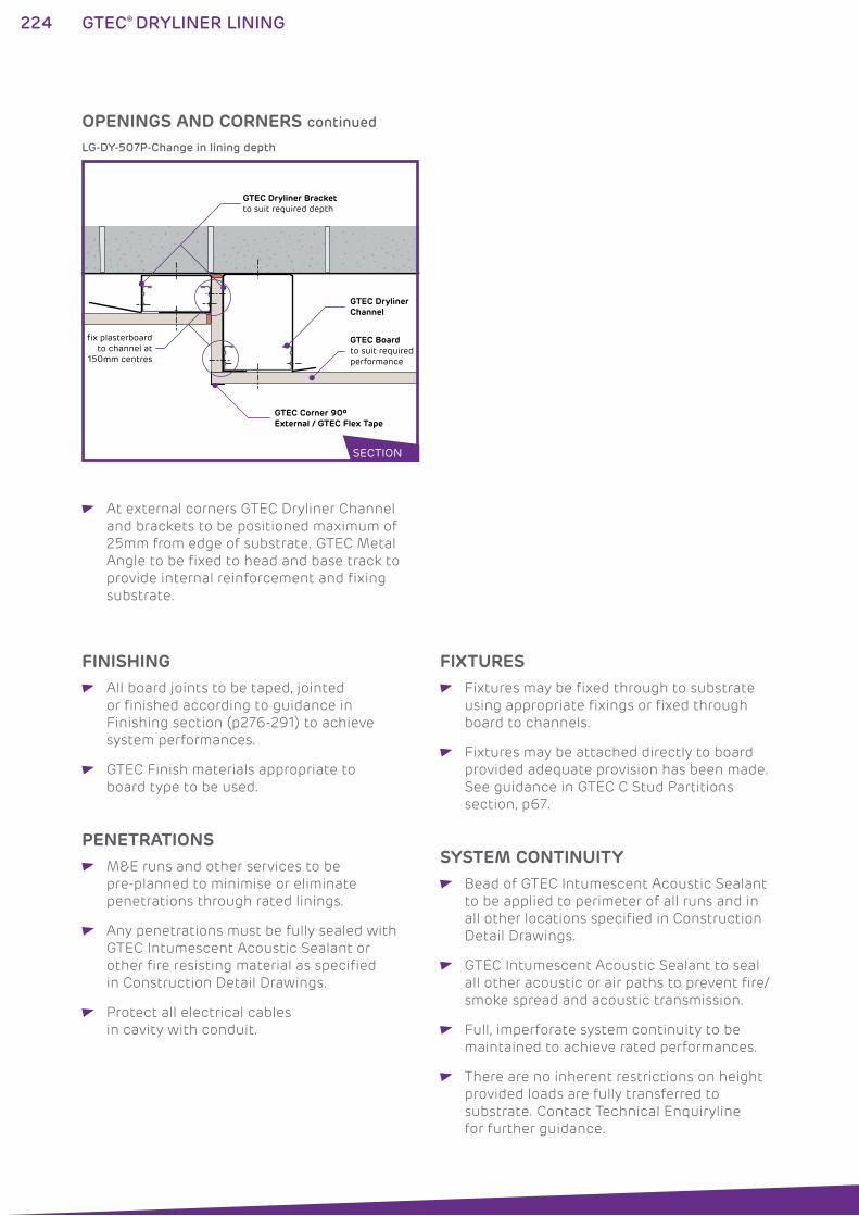
224 GTEC® DRYLINER LINING
At external corners GTEC Dryliner Channel
and brackets to be positioned maximum of
25mm from edge of substrate. GTEC Metal
Angle to be fixed to head and base track to
provide internal reinforcement and fixing
substrate.
OPENINGS AND CORNERS continued
GTEC Dryliner Channel
GTEC Corner 90º External / GTEC Flex Tape
GTEC Dryliner Bracketto suit required depth
GTEC Boardto suit required performance
fix plasterboard to channel at
150mm centres
LG-DY-507P-Change in lining depth
FINISHING All board joints to be taped, jointed
or finished according to guidance in
Finishing section (p276-291) to achieve
system performances.
GTEC Finish materials appropriate to
board type to be used.
PENETRATIONS M&E runs and other services to be
pre-planned to minimise or eliminate
penetrations through rated linings.
Any penetrations must be fully sealed with
GTEC Intumescent Acoustic Sealant or
other fire resisting material as specified
in Construction Detail Drawings.
Protect all electrical cables
in cavity with conduit.
SYSTEM CONTINUITY Bead of GTEC Intumescent Acoustic Sealant
to be applied to perimeter of all runs and in
all other locations specified in Construction
Detail Drawings.
GTEC Intumescent Acoustic Sealant to seal
all other acoustic or air paths to prevent fire/
smoke spread and acoustic transmission.
Full, imperforate system continuity to be
maintained to achieve rated performances.
There are no inherent restrictions on height
provided loads are fully transferred to
substrate. Contact Technical Enquiryline
for further guidance.
FIXTURES Fixtures may be fixed through to substrate
using appropriate fixings or fixed through
board to channels.
Fixtures may be attached directly to board
provided adequate provision has been made.
See guidance in GTEC C Stud Partitions
section, p67.
SECTION
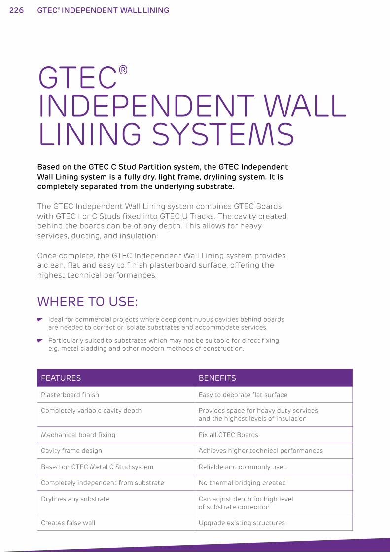
226 GTEC® INDEPENDENT WALL LINING
GTEC® INDEPENDENT WALL LINING SYSTEMSBased on the GTEC C Stud Partition system, the GTEC Independent
Wall Lining system is a fully dry, light frame, drylining system. It is
completely separated from the underlying substrate.
The GTEC Independent Wall Lining system combines GTEC Boards
with GTEC I or C Studs fixed into GTEC U Tracks. The cavity created
behind the boards can be of any depth. This allows for heavy
services, ducting, and insulation.
Once complete, the GTEC Independent Wall Lining system provides
a clean, flat and easy to finish plasterboard surface, offering the
highest technical performances.
WHERE TO USE: Ideal for commercial projects where deep continuous cavities behind boards
are needed to correct or isolate substrates and accommodate services.
Particularly suited to substrates which may not be suitable for direct fixing,
e.g. metal cladding and other modern methods of construction.
FEATURES BENEFITS
Plasterboard finish Easy to decorate flat surface
Completely variable cavity depth Provides space for heavy duty services
and the highest levels of insulation
Mechanical board fixing Fix all GTEC Boards
Cavity frame design Achieves higher technical performances
Based on GTEC Metal C Stud system Reliable and commonly used
Completely independent from substrate No thermal bridging created
Drylines any substrate Can adjust depth for high level
of substrate correction
Creates false wall Upgrade existing structures
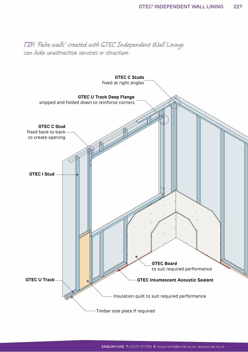
227
ENQUIRYLINE T: 01275 377789 E: [email protected] www.siniat.co.uk
GTEC® INDEPENDENT WALL LINING
GTEC Intumescent Acoustic Sealant
GTEC Boardto suit required performance
Insulation quilt to suit required performance
GTEC C Studsfixed at right angles
GTEC C Studfixed back to backto create opening
GTEC I Stud
GTEC U Track
GTEC U Track Deep Flangesnipped and folded down to reinforce corners
Timber sole plate if required
TIP: ‘False walls’ created with GTEC Independent Wall Linings can hide unattractive services or structure.
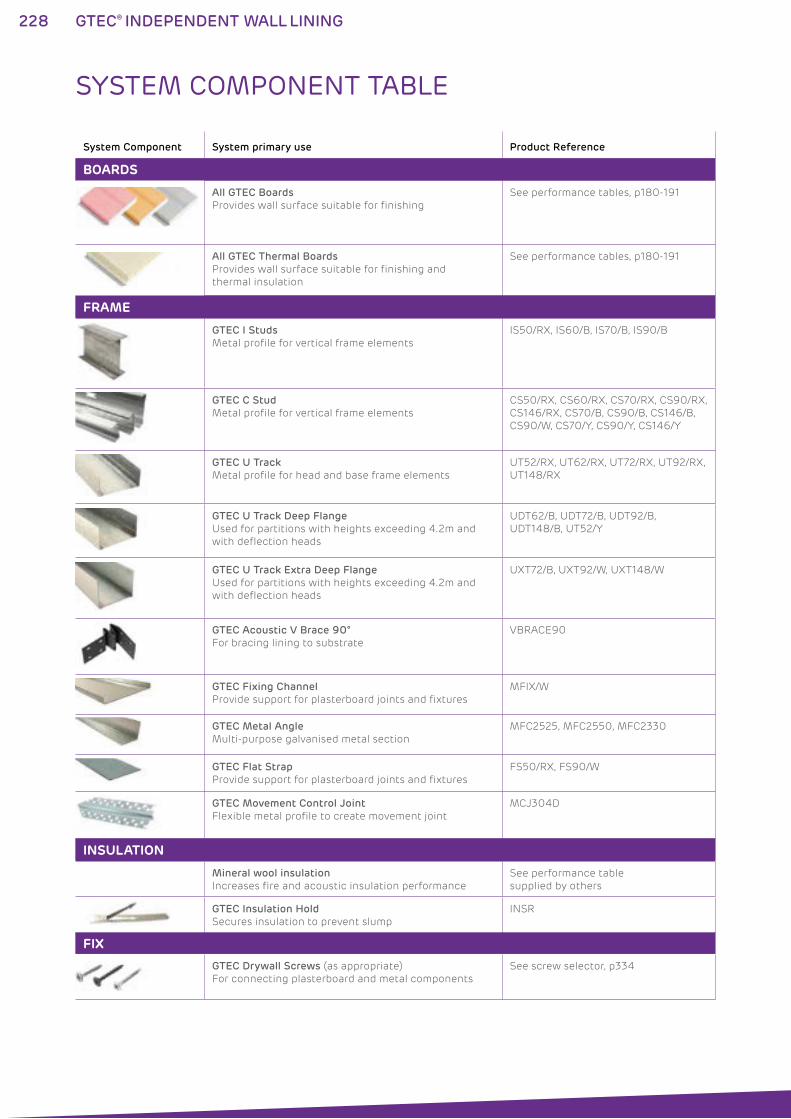
228 GTEC® INDEPENDENT WALL LINING
System Component System primary use Product Reference
BOARDS
All GTEC Boards
Provides wall surface suitable for finishing
See performance tables, p180-191
All GTEC Thermal Boards
Provides wall surface suitable for finishing and
thermal insulation
See performance tables, p180-191
FRAME
GTEC I Studs
Metal profile for vertical frame elements
IS50/RX, IS60/B, IS70/B, IS90/B
GTEC C Stud
Metal profile for vertical frame elements
CS50/RX, CS60/RX, CS70/RX, CS90/RX,
CS146/RX, CS70/B, CS90/B, CS146/B,
CS90/W, CS70/Y, CS90/Y, CS146/Y
GTEC U Track
Metal profile for head and base frame elements
UT52/RX, UT62/RX, UT72/RX, UT92/RX,
UT148/RX
GTEC U Track Deep Flange
Used for partitions with heights exceeding 4.2m and
with deflection heads
UDT62/B, UDT72/B, UDT92/B,
UDT148/B, UT52/Y
GTEC U Track Extra Deep Flange
Used for partitions with heights exceeding 4.2m and
with deflection heads
UXT72/B, UXT92/W, UXT148/W
GTEC Acoustic V Brace 90°
For bracing lining to substrate
VBRACE90
GTEC Fixing Channel
Provide support for plasterboard joints and fixtures
MFIX/W
GTEC Metal Angle
Multi-purpose galvanised metal section
MFC2525, MFC2550, MFC2330
GTEC Flat Strap
Provide support for plasterboard joints and fixtures
FS50/RX, FS90/W
GTEC Movement Control Joint
Flexible metal profile to create movement joint
MCJ304D
INSULATION
Mineral wool insulation
Increases fire and acoustic insulation performance
See performance table
supplied by others
GTEC Insulation Hold
Secures insulation to prevent slump
INSR
FIX
GTEC Drywall Screws (as appropriate)
For connecting plasterboard and metal components
See screw selector, p334
SYSTEM COMPONENT TABLE
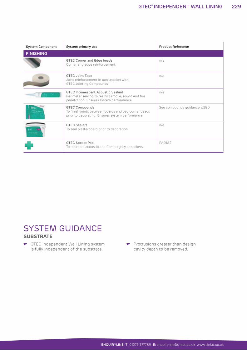
229
ENQUIRYLINE T: 01275 377789 E: [email protected] www.siniat.co.uk
GTEC® INDEPENDENT WALL LINING
System Component System primary use Product Reference
FINISHING
GTEC Corner and Edge beads
Corner and edge reinforcement
n/a
GTEC Joint Tape
Joint reinforcement in conjunction with
GTEC Jointing Compounds
n/a
GTEC Intumescent Acoustic Sealant
Perimeter sealing to restrict smoke, sound and fire
penetration. Ensures system performance
n/a
GTEC Compounds
To finish joints between boards and bed corner beads
prior to decorating. Ensures system performance
See compounds guidance, p280
GTEC Sealers
To seal plasterboard prior to decoration
n/a
GTEC Socket Pad
To maintain acoustic and fire integrity at sockets
PAD1&2
SYSTEM GUIDANCESUBSTRATE
GTEC Independent Wall Lining system
is fully independent of the substrate.
Protrusions greater than design
cavity depth to be removed.
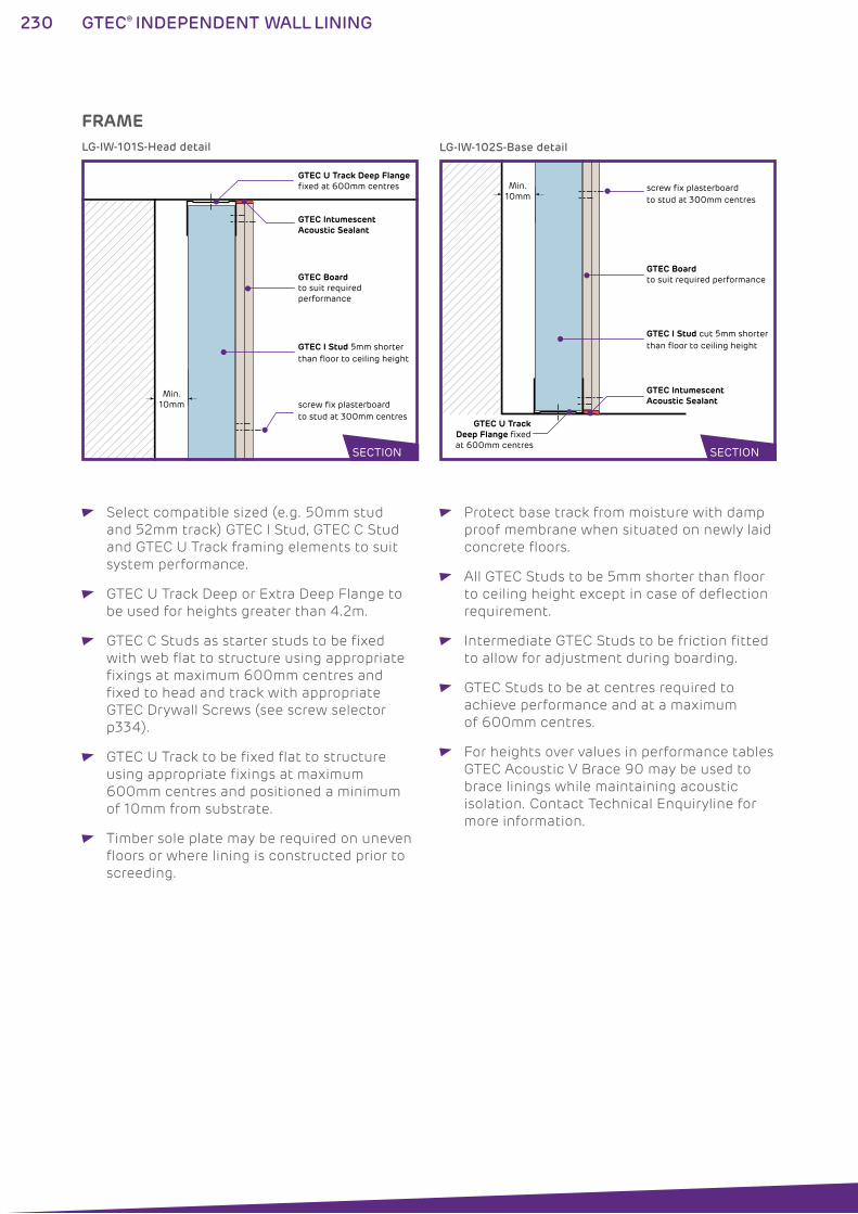
230 GTEC® INDEPENDENT WALL LINING
FRAME
GTEC Boardto suit required performance
GTEC U Track Deep Flange fixed at 600mm centres
GTEC Intumescent Acoustic Sealant
GTEC I Stud 5mm shorter than floor to ceiling height
screw fix plasterboard to stud at 300mm centres
Min. 10mm
GTEC Boardto suit required performance
GTEC Intumescent Acoustic Sealant
GTEC I Stud cut 5mm shorter than floor to ceiling height
screw fix plasterboard to stud at 300mm centres
Min. 10mm
GTEC U Track Deep Flange fixed at 600mm centres
LG-IW-101S-Head detail LG-IW-102S-Base detail
SECTION SECTION
Select compatible sized (e.g. 50mm stud
and 52mm track) GTEC I Stud, GTEC C Stud
and GTEC U Track framing elements to suit
system performance.
GTEC U Track Deep or Extra Deep Flange to
be used for heights greater than 4.2m.
GTEC C Studs as starter studs to be fixed
with web flat to structure using appropriate
fixings at maximum 600mm centres and
fixed to head and track with appropriate
GTEC Drywall Screws (see screw selector
p334).
GTEC U Track to be fixed flat to structure
using appropriate fixings at maximum
600mm centres and positioned a minimum
of 10mm from substrate.
Timber sole plate may be required on uneven
floors or where lining is constructed prior to
screeding.
Protect base track from moisture with damp
proof membrane when situated on newly laid
concrete floors.
All GTEC Studs to be 5mm shorter than floor
to ceiling height except in case of deflection
requirement.
Intermediate GTEC Studs to be friction fitted
to allow for adjustment during boarding.
GTEC Studs to be at centres required to
achieve performance and at a maximum
of 600mm centres.
For heights over values in performance tables
GTEC Acoustic V Brace 90 may be used to
brace linings while maintaining acoustic
isolation. Contact Technical Enquiryline for
more information.
231
ENQUIRYLINE T: 01275 377789 E: [email protected] www.siniat.co.uk
GTEC® INDEPENDENT WALL LINING
INSULATION Any insulation to be of type and thickness
to achieve performance and installed in a
continuous layer between and behind studs
to suit required performance.
Where insulation may be expected to slump
suspend from GTEC Insulation Hold strips
fixed across studs, 150mm from top of
partition and at 1200mm vertical centres.
BOARDING GTEC Independent Lining system is suitable
for single, double and multiple layer boarding.
Select base layer(s) and finishing layer(s)
GTEC Boards by consulting System
Performance Tables, p180-191, and Product
Specification, p294-307, to achieve required
performance. See High Performance Boards
guide p12 for further selection information.
Boards to be 5mm less than floor to ceiling
height.
Strips of board 300mm wide or less to be
avoided by stud location rearrangement.
Boards to be mechanically fixed to studs
at 300mm centres using appropriate GTEC
Drywall Screws. See screw selector p334.
Base layers of boarding may be temporarily
fixed at 600mm centres providing final layer
is fixed through to stud at 300mm centres
Board edges to be centred over studs.
Stagger all board joints between layers.
Stagger all board joints on opposing sides
of partition.
Over-height single layer boarding only:
Where partition height exceeds board height
fix boards to continuous band of GTEC Flat
Strap FS90/W or GTEC MFIX behind all
horizontal joints to maintain fire integrity.
Over-height multiple layer boarding only:
Where partition height exceeds board
height for double or multiple layer
boarding fix outer layer of boards to
continuous band of GTEC Flat Strap
FS50/RX behind all horizontal joints.
Thermal Boards only:
Select GTEC Thermal Board type and
thickness according to desired thermal
value and requirement for vapour barrier.
GTEC Thermal Board thickness may be
reduced by utilising higher insulation
grade boards, e.g. GTEC Thermal K Board.
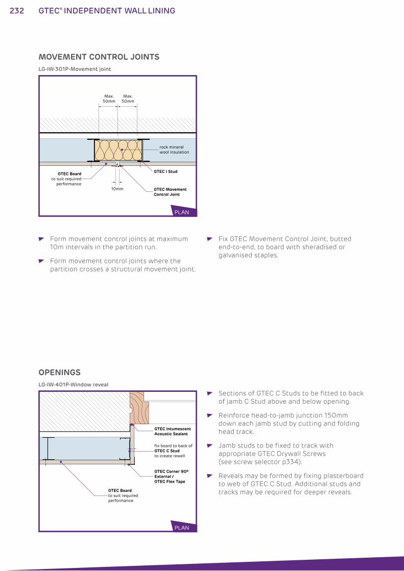
232 GTEC® INDEPENDENT WALL LINING
MOVEMENT CONTROL JOINTS
OPENINGS
rock mineral wool insulation
10mm GTEC MovementControl Joint
GTEC I Stud
Max. 50mm
Max. 50mm
GTEC Boardto suit required
performance
GTEC Boardto suit requiredperformance
GTEC Corner 90º External /GTEC Flex Tape
fix board to back of GTEC C Stud to create rewell
GTEC Intumescent Acoustic Sealant
LG-IW-301P-Movement joint
LG-IW-401P-Window reveal
Form movement control joints at maximum
10m intervals in the partition run.
Form movement control joints where the
partition crosses a structural movement joint.
Fix GTEC Movement Control Joint, butted
end-to-end, to board with sheradised or
galvanised staples.
Sections of GTEC C Studs to be fitted to back
of jamb C Stud above and below opening.
Reinforce head-to-jamb junction 150mm
down each jamb stud by cutting and folding
head track.
Jamb studs to be fixed to track with
appropriate GTEC Drywall Screws
(see screw selector p334).
Reveals may be formed by fixing plasterboard
to web of GTEC C Stud. Additional studs and
tracks may be required for deeper reveals.
PLAN
PLAN
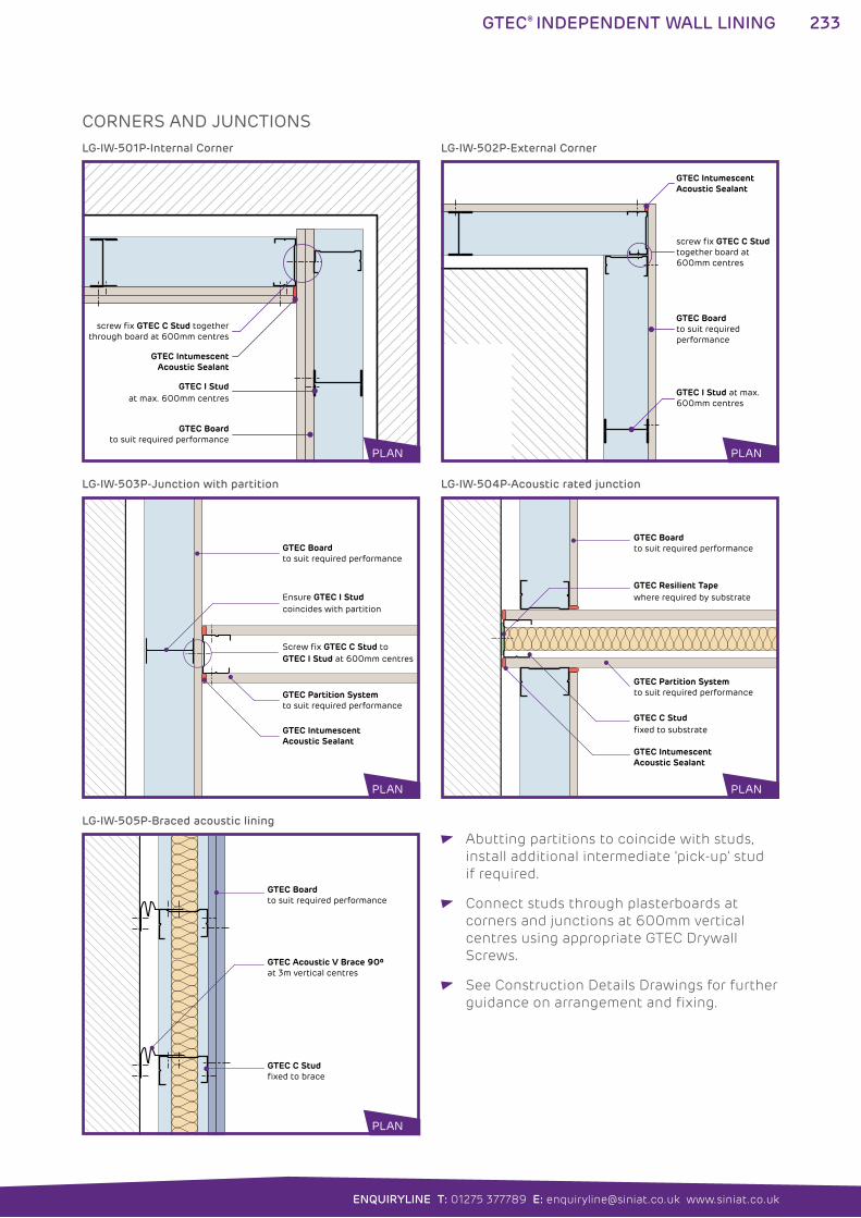
233
ENQUIRYLINE T: 01275 377789 E: [email protected] www.siniat.co.uk
GTEC® INDEPENDENT WALL LINING
Abutting partitions to coincide with studs,
install additional intermediate ‘pick-up’ stud
if required.
Connect studs through plasterboards at
corners and junctions at 600mm vertical
centres using appropriate GTEC Drywall
Screws.
See Construction Details Drawings for further
guidance on arrangement and fixing.
CORNERS AND JUNCTIONS
screw fix GTEC C Stud together through board at 600mm centres
GTEC IntumescentAcoustic Sealant
GTEC Boardto suit required performance
GTEC I Studat max. 600mm centres
PLAN
GTEC Boardto suit required performance
GTEC Intumescent Acoustic Sealant
Screw fix GTEC C Stud to GTEC I Stud at 600mm centres
Ensure GTEC I Stud coincides with partition
GTEC Partition Systemto suit required performance
GTEC Boardto suit required performance
GTEC Acoustic V Brace 90ºat 3m vertical centres
GTEC C Studfixed to brace
GTEC Boardto suit required performance
GTEC Intumescent Acoustic Sealant
GTEC Resilient Tapewhere required by substrate
GTEC C Studfixed to substrate
GTEC Partition Systemto suit required performance
screw fix GTEC C Studtogether board at 600mm centres
GTEC Intumescent Acoustic Sealant
GTEC Boardto suit requiredperformance
GTEC I Stud at max. 600mm centres
LG-IW-501P-Internal Corner
LG-IW-503P-Junction with partition
LG-IW-505P-Braced acoustic lining
LG-IW-504P-Acoustic rated junction
LG-IW-502P-External Corner
PLAN
PLAN
PLAN
PLAN
PLAN
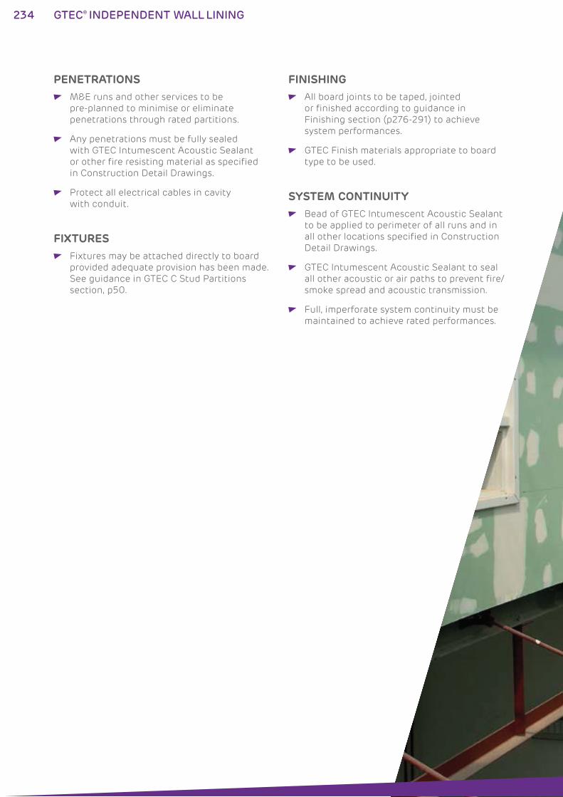
234 GTEC® INDEPENDENT WALL LINING
FINISHING All board joints to be taped, jointed
or finished according to guidance in
Finishing section (p276-291) to achieve
system performances.
GTEC Finish materials appropriate to board
type to be used.
PENETRATIONS M&E runs and other services to be
pre-planned to minimise or eliminate
penetrations through rated partitions.
Any penetrations must be fully sealed
with GTEC Intumescent Acoustic Sealant
or other fire resisting material as specified
in Construction Detail Drawings.
Protect all electrical cables in cavity
with conduit.SYSTEM CONTINUITY
Bead of GTEC Intumescent Acoustic Sealant
to be applied to perimeter of all runs and in
all other locations specified in Construction
Detail Drawings.
GTEC Intumescent Acoustic Sealant to seal
all other acoustic or air paths to prevent fire/
smoke spread and acoustic transmission.
Full, imperforate system continuity must be
maintained to achieve rated performances.
FIXTURES Fixtures may be attached directly to board
provided adequate provision has been made.
See guidance in GTEC C Stud Partitions
section, p50.
236 GTEC® PREGYBEL INDEPENDENT LINING
GTEC® PREGYBEL INDEPENDENT LINING SYSTEMSSound absorbing wall linings can be created using the GTEC Pregybel
Independent Lining system to improve acoustic comfort by reducing
sound reflection in larger spaces.
Used above pedestrian height perforated GTEC Pregybel Board is
applied to the GTEC Independent Wall Lining system with insulation
for an easy to install sound absorbing lining. Flexible design and simple
specification can be achieved by using these standard components.
Attractive designs are possible created with the variety of patterns in
the GTEC Pregybel range.
Standalone acoustic panels can also be created to mount to walls to
improve sound absorption.
WHERE TO USE: GTEC Pregybel Independent Linings are used in commercial
applications to improve the acoustic conditions in large spaces.
FEATURES BENEFITS
Variable cavity depth Cavity size can be optimised for service and
insulation requirements
Up to Class B acoustic absorption
Utilises GTEC Independent Wall Lining framing One set of components on site.
Easy to install.
Creates a false wall Can be used to upgrade existing structures
Perforated boards in a range of patterns Provides a range of aesthetic options for
variation in large spaces
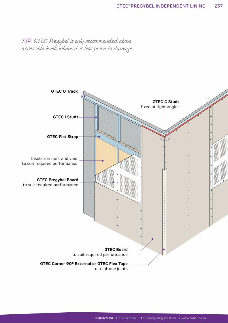
237
ENQUIRYLINE T: 01275 377789 E: [email protected] www.siniat.co.uk
GTEC® PREGYBEL INDEPENDENT LINING
GTEC Corner 90º External or GTEC Flex Tapeto reinforce joints
Insulation quilt and void to suit required performance
GTEC C Studsfixed at right angles
GTEC Pregybel Boardto suit required performance
GTEC I Studs
GTEC Flat Strap
GTEC U Track
GTEC Boardto suit required performance
TIP: GTEC Pregybel is only recommended above accessible levels where it is less prone to damage.
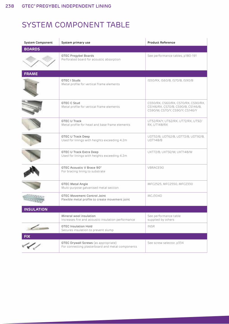
238 GTEC® PREGYBEL INDEPENDENT LINING
System Component System primary use Product Reference
BOARDS
GTEC Pregybel Boards
Perforated board for acoustic absorption
See performance tables, p180-191
FRAME
GTEC I Studs
Metal profile for vertical frame elements
IS50/RX, IS60/B, IS70/B, IS90/B
GTEC C Stud
Metal profile for vertical frame elements
CS50/RX, CS60/RX, CS70/RX, CS90/RX,
CS146/RX, CS70/B, CS90/B, CS146/B,
CS90/W, CS70/Y, CS90/Y, CS146/Y
GTEC U Track
Metal profile for head and base frame elements
UT52/RX/Y, UT62/RX, UT72/RX, UT92/
RX, UT148/RX
GTEC U Track Deep
Used for linings with heights exceeding 4.2m
UDT52/B, UDT62/B, UDT72/B, UDT92/B,
UDT148/B
GTEC U Track Extra Deep
Used for linings with heights exceeding 4.2m
UXT72/B, UXT92/W, UXT148/W
GTEC Acoustic V Brace 90°
For bracing lining to substrate
VBRACE90
GTEC Metal Angle
Multi-purpose galvanised metal section
MFC2525, MFC2550, MFC2330
GTEC Movement Control Joint
Flexible metal profile to create movement jointMCJ304D
INSULATION
Mineral wool insulation
Increases fire and acoustic insulation performance
See performance table
supplied by others
GTEC Insulation Hold
Secures insulation to prevent slump
INSR
FIX
GTEC Drywall Screws (as appropriate)
For connecting plasterboard and metal components
See screw selector, p334
SYSTEM COMPONENT TABLE
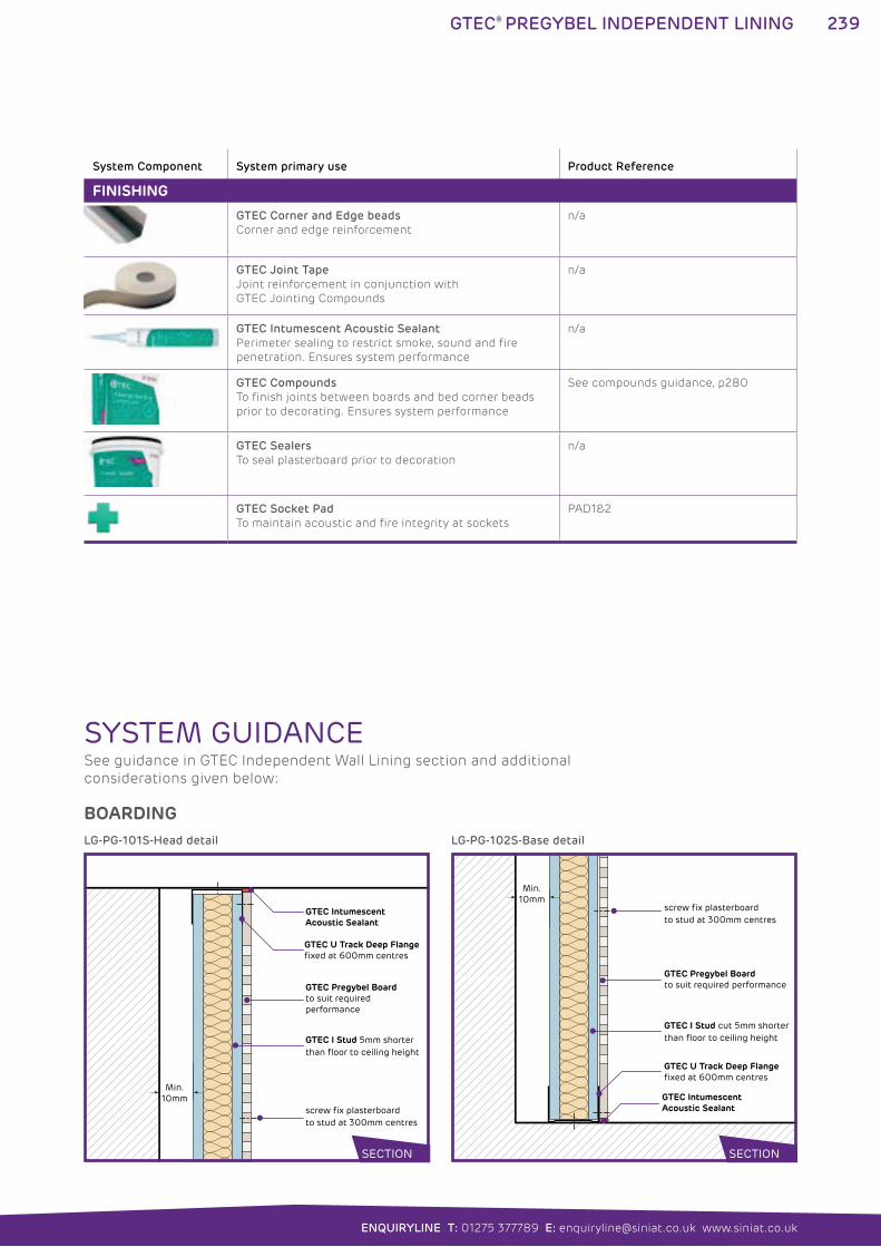
239
ENQUIRYLINE T: 01275 377789 E: [email protected] www.siniat.co.uk
GTEC® PREGYBEL INDEPENDENT LINING
System Component System primary use Product Reference
FINISHING
GTEC Corner and Edge beads
Corner and edge reinforcement
n/a
GTEC Joint Tape
Joint reinforcement in conjunction with
GTEC Jointing Compounds
n/a
GTEC Intumescent Acoustic Sealant
Perimeter sealing to restrict smoke, sound and fire
penetration. Ensures system performance
n/a
GTEC Compounds
To finish joints between boards and bed corner beads
prior to decorating. Ensures system performance
See compounds guidance, p280
GTEC Sealers
To seal plasterboard prior to decoration
n/a
GTEC Socket Pad
To maintain acoustic and fire integrity at sockets
PAD1&2
GTEC Pregybel Boardto suit required performance
GTEC U Track Deep Flange fixed at 600mm centres
GTEC Intumescent Acoustic Sealant
GTEC I Stud 5mm shorter than floor to ceiling height
screw fix plasterboard to stud at 300mm centres
Min. 10mm
GTEC Pregybel Boardto suit required performance
GTEC Intumescent Acoustic Sealant
GTEC I Stud cut 5mm shorter than floor to ceiling height
screw fix plasterboard to stud at 300mm centres
Min. 10mm
GTEC U Track Deep Flange fixed at 600mm centres
LG-PG-101S-Head detail LG-PG-102S-Base detail
SYSTEM GUIDANCE
BOARDING
See guidance in GTEC Independent Wall Lining section and additional
considerations given below:
SECTION SECTION
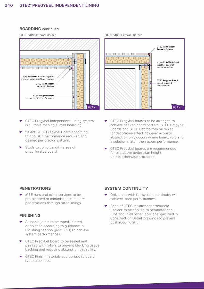
240 GTEC® PREGYBEL INDEPENDENT LINING
GTEC Pregybel Independent Lining system
is suitable for single layer boarding.
Select GTEC Pregybel Board according
to acoustic performance required and
desired perforation pattern.
Studs to coincide with areas of
unperforated board.
GTEC Pregybel boards to be arranged to
achieve desired board pattern. GTEC Pregybel
Boards and GTEC Boards may be mixed
for decorative effect however acoustic
absorption only occurs where board, void and
insulation match the system performance.
GTEC Pregybel boards are recommended
for use above pedestrian height
unless otherwise protected.
BOARDING continued
screw fix GTEC C Stud together through board at 600mm centres
GTEC IntumescentAcoustic Sealant
GTEC Pregybel Boardto suit required performance
screw fix GTEC C Studtogether board at 600mm centres
GTEC Intumescent Acoustic Sealant
GTEC Pregybel Boardto suit requiredperformance
LG-PG-501P-Internal Corner LG-PG-502P-External Corner
PLAN PLAN
FINISHING All board joints to be taped, jointed
or finished according to guidance in
Finishing section (p276-291) to achieve
system performances.
GTEC Pregybel Board to be sealed and
painted with rollers to prevent blocking tissue
backing and reducing absorption capability.
GTEC Finish materials appropriate to board
type to be used.
PENETRATIONS M&E runs and other services to be
pre-planned to minimise or eliminate
penetrations through rated linings.
SYSTEM CONTINUITY Only areas with full system continuity will
achieve rated performances.
Bead of GTEC Intumescent Acoustic
Sealant to be applied to perimeter of all
runs and in all other locations specified in
Construction Detail Drawings to prevent
dust accumulation.
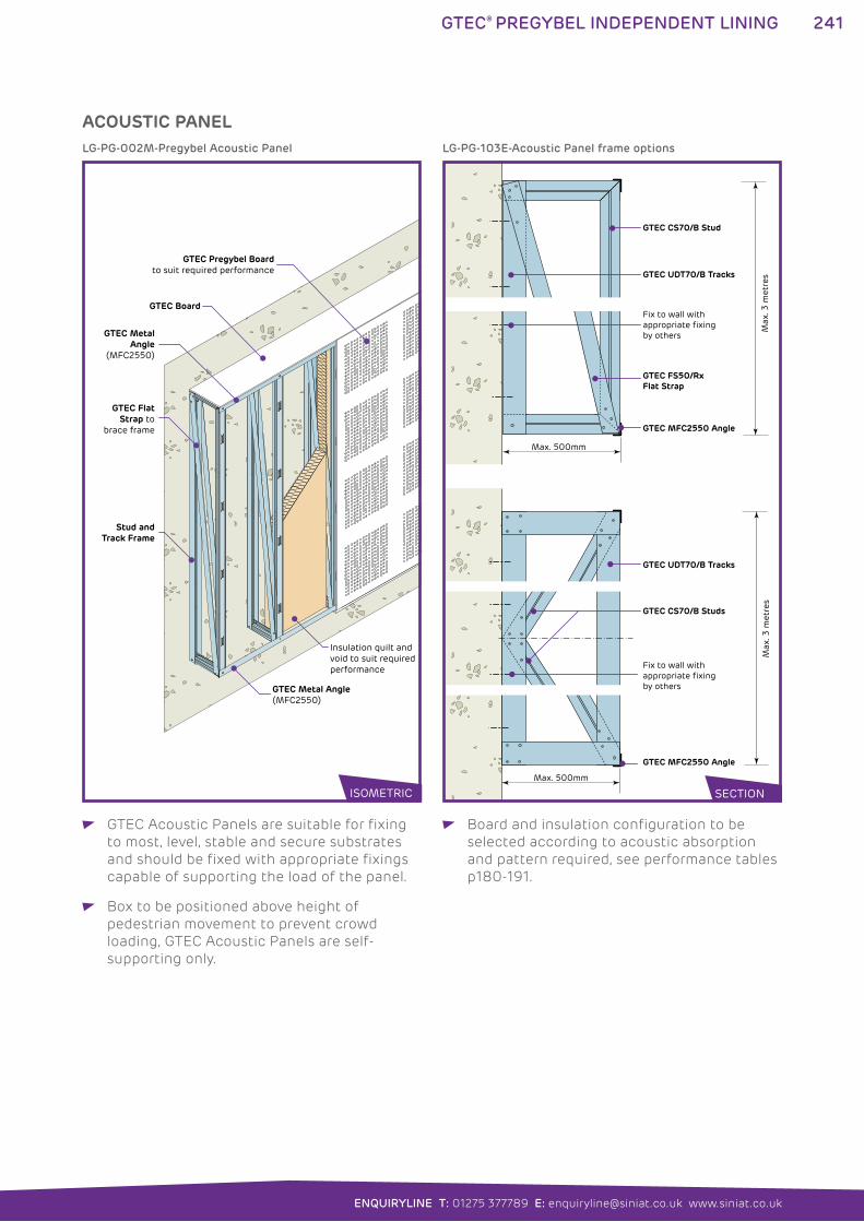
241
ENQUIRYLINE T: 01275 377789 E: [email protected] www.siniat.co.uk
GTEC® PREGYBEL INDEPENDENT LINING
GTEC Acoustic Panels are suitable for fixing
to most, level, stable and secure substrates
and should be fixed with appropriate fixings
capable of supporting the load of the panel.
Box to be positioned above height of
pedestrian movement to prevent crowd
loading, GTEC Acoustic Panels are self-
supporting only.
Board and insulation configuration to be
selected according to acoustic absorption
and pattern required, see performance tables
p180-191.
ACOUSTIC PANEL
Stud and Track Frame
GTEC FlatStrap to
brace frame
GTEC Board
Insulation quilt andvoid to suit requiredperformance
GTEC Metal Angle(MFC2550)
GTEC MetalAngle
(MFC2550)
GTEC Pregybel Boardto suit required performance
LG-PG-002M-Pregybel Acoustic Panel
Max
. 3 m
etre
s
Max. 500mm
GTEC CS70/B Stud
GTEC UDT70/B Tracks
GTEC FS50/Rx Flat Strap
Fix to wall with appropriate fixingby others
GTEC MFC2550 Angle
Max
. 3 m
etre
sMax. 500mm
GTEC CS70/B Studs
Fix to wall with appropriate fixing by others
GTEC UDT70/B Tracks
GTEC MFC2550 Angle
LG-PG-103E-Acoustic Panel frame options
SECTIONISOMETRIC

GTEC® FIRE PROTECTION242
243
ENQUIRYLINE T: 01275 377789 E: [email protected] www.siniat.co.uk
FIRE PROTECTION
Performance Tables
GTEC Shaftwall systems 244
GTEC Shaftwall Stairwell systems 248
GTEC Horizontal Shaftwall systems 249
GTEC Encasement systems 250
GTEC Shaftwall systems 254
GTEC Encasement systems 268
GTEC Shaftwall range uses a specially designed system to protect voids and shafts in buildings. It resists pressure changes and enables installation from one side of the shaft only. GTEC Encasement Fire Protection offers rapid installation of fire protection around columns and beams.
243
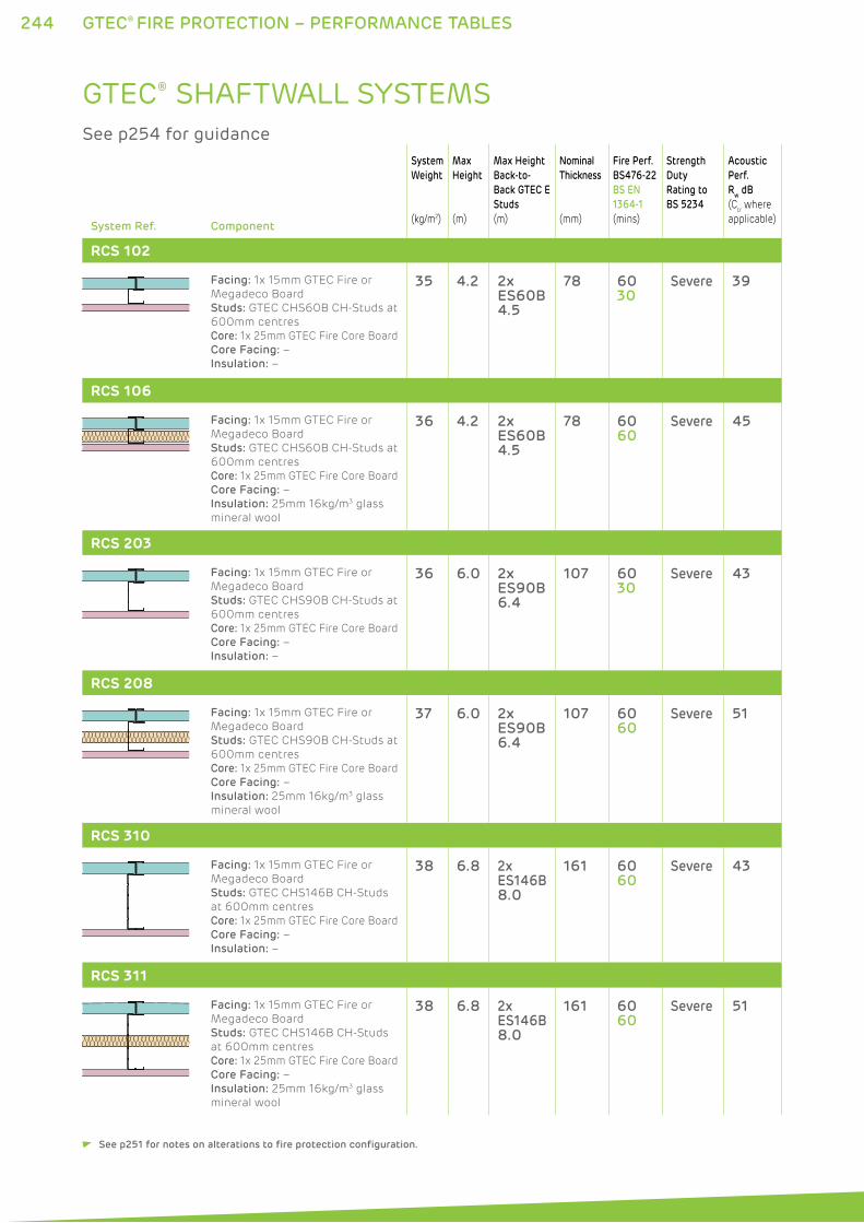
244 GTEC® FIRE PROTECTION – PERFORMANCE TABLES
System Ref. Component
System
Weight
(kg/m2)
Max
Height
(m)
Max Height
Back-to-
Back GTEC E
Studs
(m)
Nominal
Thickness
(mm)
Fire Perf.
BS476-22
BS EN
1364-1
(mins)
Strength
Duty
Rating to
BS 5234
Acoustic
Perf.
Rw dB
(Ctr where
applicable)
RCS 102
Facing: 1x 15mm GTEC Fire or
Megadeco Board
Studs: GTEC CHS60B CH-Studs at
600mm centres
Core: 1x 25mm GTEC Fire Core Board
Core Facing: –
Insulation: –
35 4.2 2x ES60B4.5
78 6030
Severe 39
RCS 106
Facing: 1x 15mm GTEC Fire or
Megadeco Board
Studs: GTEC CHS60B CH-Studs at
600mm centres
Core: 1x 25mm GTEC Fire Core Board
Core Facing: –
Insulation: 25mm 16kg/m3 glass
mineral wool
36 4.2 2x ES60B4.5
78 6060
Severe 45
RCS 203
Facing: 1x 15mm GTEC Fire or
Megadeco Board
Studs: GTEC CHS90B CH-Studs at
600mm centres
Core: 1x 25mm GTEC Fire Core Board
Core Facing: –
Insulation: –
36 6.0 2x ES90B6.4
107 6030
Severe 43
RCS 208
Facing: 1x 15mm GTEC Fire or
Megadeco Board
Studs: GTEC CHS90B CH-Studs at
600mm centres
Core: 1x 25mm GTEC Fire Core Board
Core Facing: –
Insulation: 25mm 16kg/m3 glass
mineral wool
37 6.0 2x ES90B6.4
107 6060
Severe 51
RCS 310
Facing: 1x 15mm GTEC Fire or
Megadeco Board
Studs: GTEC CHS146B CH-Studs
at 600mm centres
Core: 1x 25mm GTEC Fire Core Board
Core Facing: –
Insulation: –
38 6.8 2x ES146B8.0
161 6060
Severe 43
RCS 311
Facing: 1x 15mm GTEC Fire or
Megadeco Board
Studs: GTEC CHS146B CH-Studs
at 600mm centres
Core: 1x 25mm GTEC Fire Core Board
Core Facing: –
Insulation: 25mm 16kg/m3 glass
mineral wool
38 6.8 2x ES146B8.0
161 6060
Severe 51
GTEC® SHAFTWALL SYSTEMS See p254 for guidance
See p251 for notes on alterations to fire protection configuration.
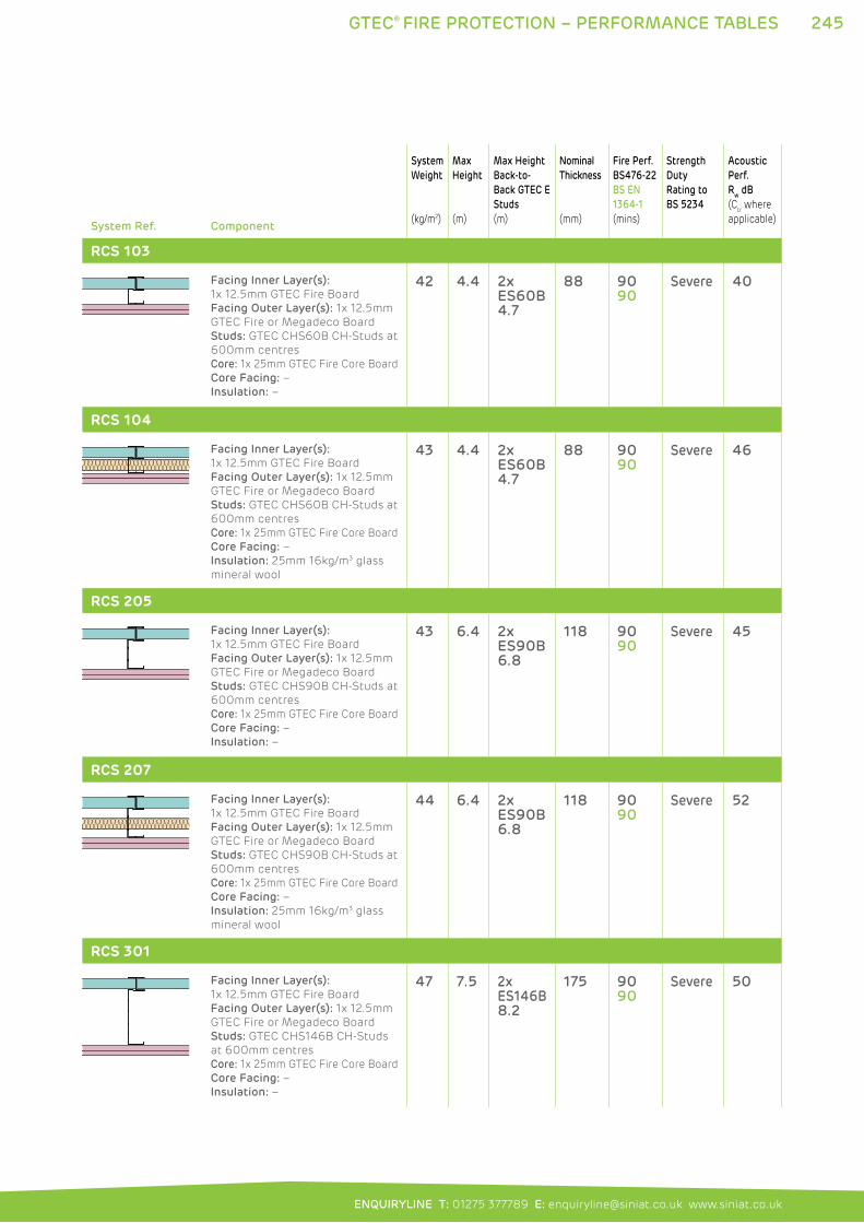
245GTEC® FIRE PROTECTION – PERFORMANCE TABLES
ENQUIRYLINE T: 01275 377789 E: [email protected] www.siniat.co.uk
System Ref. Component
System
Weight
(kg/m2)
Max
Height
(m)
Max Height
Back-to-
Back GTEC E
Studs
(m)
Nominal
Thickness
(mm)
Fire Perf.
BS476-22
BS EN
1364-1
(mins)
Strength
Duty
Rating to
BS 5234
Acoustic
Perf.
Rw dB
(Ctr where
applicable)
RCS 103
Facing Inner Layer(s):
1x 12.5mm GTEC Fire Board
Facing Outer Layer(s): 1x 12.5mm
GTEC Fire or Megadeco Board
Studs: GTEC CHS60B CH-Studs at
600mm centres
Core: 1x 25mm GTEC Fire Core Board
Core Facing: –
Insulation: –
42 4.4 2x ES60B4.7
88 9090
Severe 40
RCS 104
Facing Inner Layer(s):
1x 12.5mm GTEC Fire Board
Facing Outer Layer(s): 1x 12.5mm
GTEC Fire or Megadeco Board
Studs: GTEC CHS60B CH-Studs at
600mm centres
Core: 1x 25mm GTEC Fire Core Board
Core Facing: –
Insulation: 25mm 16kg/m3 glass
mineral wool
43 4.4 2x ES60B4.7
88 9090
Severe 46
RCS 205
Facing Inner Layer(s):
1x 12.5mm GTEC Fire Board
Facing Outer Layer(s): 1x 12.5mm
GTEC Fire or Megadeco Board
Studs: GTEC CHS90B CH-Studs at
600mm centres
Core: 1x 25mm GTEC Fire Core Board
Core Facing: –
Insulation: –
43 6.4 2x ES90B6.8
118 9090
Severe 45
RCS 207
Facing Inner Layer(s):
1x 12.5mm GTEC Fire Board
Facing Outer Layer(s): 1x 12.5mm
GTEC Fire or Megadeco Board
Studs: GTEC CHS90B CH-Studs at
600mm centres
Core: 1x 25mm GTEC Fire Core Board
Core Facing: –
Insulation: 25mm 16kg/m3 glass
mineral wool
44 6.4 2x ES90B6.8
118 9090
Severe 52
RCS 301
Facing Inner Layer(s):
1x 12.5mm GTEC Fire Board
Facing Outer Layer(s): 1x 12.5mm
GTEC Fire or Megadeco Board
Studs: GTEC CHS146B CH-Studs
at 600mm centres
Core: 1x 25mm GTEC Fire Core Board
Core Facing: –
Insulation: –
47 7.5 2x ES146B8.2
175 9090
Severe 50
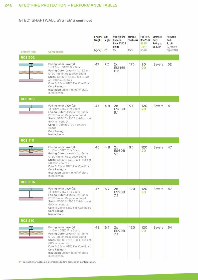
246 GTEC® FIRE PROTECTION – PERFORMANCE TABLES
System Ref. Component
System
Weight
(kg/m2)
Max
Height
(m)
Max Height
Back-to-
Back GTEC E
Studs
(m)
Nominal
Thickness
(mm)
Fire Perf.
BS476-22
BS EN
1364-1
(mins)
Strength
Duty
Rating to
BS 5234
Acoustic
Perf.
Rw dB
(Ctr where
applicable)
RCS 302
Facing Inner Layer(s):
1x 12.5mm GTEC Fire Board
Facing Outer Layer(s): 1x 12.5mm
GTEC Fire or Megadeco Board
Studs: GTEC CHS146B CH-Studs
at 600mm centres
Core: 1x 25mm GTEC Fire Core Board
Core Facing: –
Insulation: 25mm 16kg/m3 glass
mineral wool
47 7.5 2x ES146B8.2
175 9090
Severe 52
RCS 109
Facing Inner Layer(s):
1x 15mm GTEC Fire Board
Facing Outer Layer(s): 1x 15mm
GTEC Fire or Megadeco Board
Studs: GTEC CHS60B CH-Studs at
600mm centres
Core: 1x 25mm GTEC Fire Core
Board
Core Facing: –
Insulation: –
45 4.8 2x ES60B5.1
95 12090
Severe 41
RCS 110
Facing Inner Layer(s):
1x 15mm GTEC Fire Board
Facing Outer Layer(s): 1x 15mm
GTEC Fire or Megadeco Board
Studs: GTEC CHS60B CH-Studs at
600mm centres
Core: 1x 25mm GTEC Fire Core Board
Core Facing: –
Insulation: 25mm 16kg/m3 glass
mineral wool
46 4.8 2x ES60B5.1
95 12090
Severe 47
RCS 206
Facing Inner Layer(s):
1x 15mm GTEC Fire Board
Facing Outer Layer(s): 1x 15mm
GTEC Fire or Megadeco Board
Studs: GTEC CHS90B CH-Studs at
600mm centres
Core: 1x 25mm GTEC Fire Core Board
Core Facing: –
Insulation: –
47 6.7 2x ES90B7.1
120 12090
Severe 47
RCS 210
Facing Inner Layer(s):
1x 15mm GTEC Fire Board
Facing Outer Layer(s): 1x 15mm
GTEC Fire or Megadeco Board
Studs: GTEC CHS90B CH-Studs at
600mm centres
Core: 1x 25mm GTEC Fire Core Board
Core Facing: –
Insulation: 25mm 16kg/m3 glass
mineral wool
48 6.7 2x ES90B7.1
120 12090
Severe 54
GTEC® SHAFTWALL SYSTEMS continued
See p251 for notes on alterations to fire protection configuration.
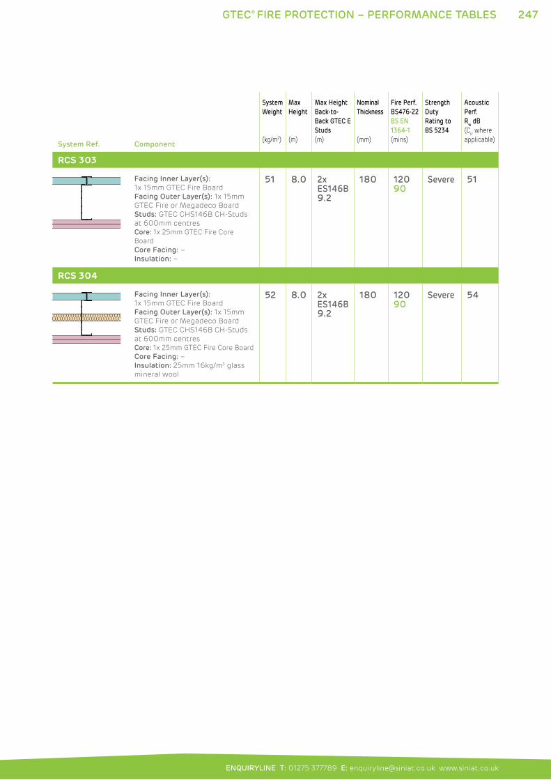
247GTEC® FIRE PROTECTION – PERFORMANCE TABLES
ENQUIRYLINE T: 01275 377789 E: [email protected] www.siniat.co.uk
System Ref. Component
System
Weight
(kg/m2)
Max
Height
(m)
Max Height
Back-to-
Back GTEC E
Studs
(m)
Nominal
Thickness
(mm)
Fire Perf.
BS476-22
BS EN
1364-1
(mins)
Strength
Duty
Rating to
BS 5234
Acoustic
Perf.
Rw dB
(Ctr where
applicable)
RCS 303
Facing Inner Layer(s):
1x 15mm GTEC Fire Board
Facing Outer Layer(s): 1x 15mm
GTEC Fire or Megadeco Board
Studs: GTEC CHS146B CH-Studs
at 600mm centres
Core: 1x 25mm GTEC Fire Core
Board
Core Facing: –
Insulation: –
51 8.0 2x ES146B9.2
180 12090
Severe 51
RCS 304
Facing Inner Layer(s):
1x 15mm GTEC Fire Board
Facing Outer Layer(s): 1x 15mm
GTEC Fire or Megadeco Board
Studs: GTEC CHS146B CH-Studs
at 600mm centres
Core: 1x 25mm GTEC Fire Core Board
Core Facing: –
Insulation: 25mm 16kg/m3 glass
mineral wool
52 8.0 2x ES146B9.2
180 12090
Severe 54
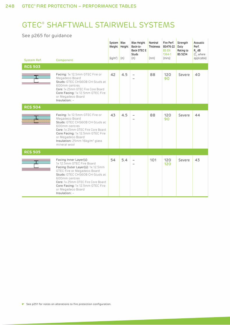
248 GTEC® FIRE PROTECTION – PERFORMANCE TABLES
System Ref. Component
System
Weight
(kg/m2)
Max
Height
(m)
Max Height
Back-to-
Back GTEC E
Studs
(m)
Nominal
Thickness
(mm)
Fire Perf.
BS476-22
BS EN
1364-1
(mins)
Strength
Duty
Rating to
BS 5234
Acoustic
Perf.
Rw dB
(Ctr where
applicable)
RCS 503
Facing: 1x 12.5mm GTEC Fire or
Megadeco Board
Studs: GTEC CHS60B CH-Studs at
600mm centres
Core: 1x 25mm GTEC Fire Core Board
Core Facing: 1x 12.5mm GTEC Fire
or Megadeco Board
Insulation: –
42 4.5 ––
88 12090
Severe 40
RCS 504
Facing: 1x 12.5mm GTEC Fire or
Megadeco Board
Studs: GTEC CHS60B CH-Studs at
600mm centres
Core: 1x 25mm GTEC Fire Core Board
Core Facing: 1x 12.5mm GTEC Fire
or Megadeco Board
Insulation: 25mm 16kg/m3 glass
mineral wool
43 4.5 ––
88 12090
Severe 44
RCS 505
Facing Inner Layer(s):
1x 12.5mm GTEC Fire Board
Facing Outer Layer(s): 1x 12.5mm
GTEC Fire or Megadeco Board
Studs: GTEC CHS60B CH-Studs at
600mm centres
Core: 1x 25mm GTEC Fire Core Board
Core Facing: 1x 12.5mm GTEC Fire
or Megadeco Board
Insulation: –
54 5.4 ––
101 120120
Severe 43
GTEC® SHAFTWALL STAIRWELL SYSTEMS See p265 for guidance
See p251 for notes on alterations to fire protection configuration.
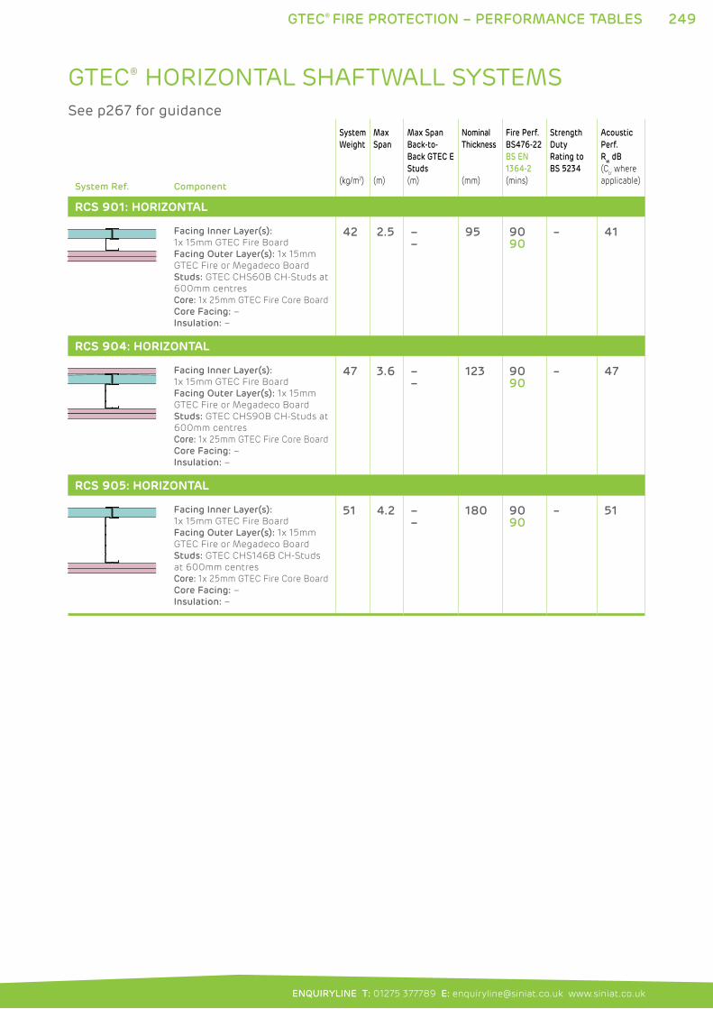
249GTEC® FIRE PROTECTION – PERFORMANCE TABLES
ENQUIRYLINE T: 01275 377789 E: [email protected] www.siniat.co.uk
System Ref. Component
System
Weight
(kg/m2)
Max
Span
(m)
Max Span
Back-to-
Back GTEC E
Studs
(m)
Nominal
Thickness
(mm)
Fire Perf.
BS476-22
BS EN
1364-2
(mins)
Strength
Duty
Rating to
BS 5234
Acoustic
Perf.
Rw dB
(Ctr where
applicable)
RCS 901: HORIZONTAL
Facing Inner Layer(s):
1x 15mm GTEC Fire Board
Facing Outer Layer(s): 1x 15mm
GTEC Fire or Megadeco Board
Studs: GTEC CHS60B CH-Studs at
600mm centres
Core: 1x 25mm GTEC Fire Core Board
Core Facing: –
Insulation: –
42 2.5 ––
95 9090
– 41
RCS 904: HORIZONTAL
Facing Inner Layer(s):
1x 15mm GTEC Fire Board
Facing Outer Layer(s): 1x 15mm
GTEC Fire or Megadeco Board
Studs: GTEC CHS90B CH-Studs at
600mm centres
Core: 1x 25mm GTEC Fire Core Board
Core Facing: –
Insulation: –
47 3.6 ––
123 9090
– 47
RCS 905: HORIZONTAL
Facing Inner Layer(s):
1x 15mm GTEC Fire Board
Facing Outer Layer(s): 1x 15mm
GTEC Fire or Megadeco Board
Studs: GTEC CHS146B CH-Studs
at 600mm centres
Core: 1x 25mm GTEC Fire Core Board
Core Facing: –
Insulation: –
51 4.2 ––
180 9090
– 51
GTEC® HORIZONTAL SHAFTWALL SYSTEMS See p267 for guidance
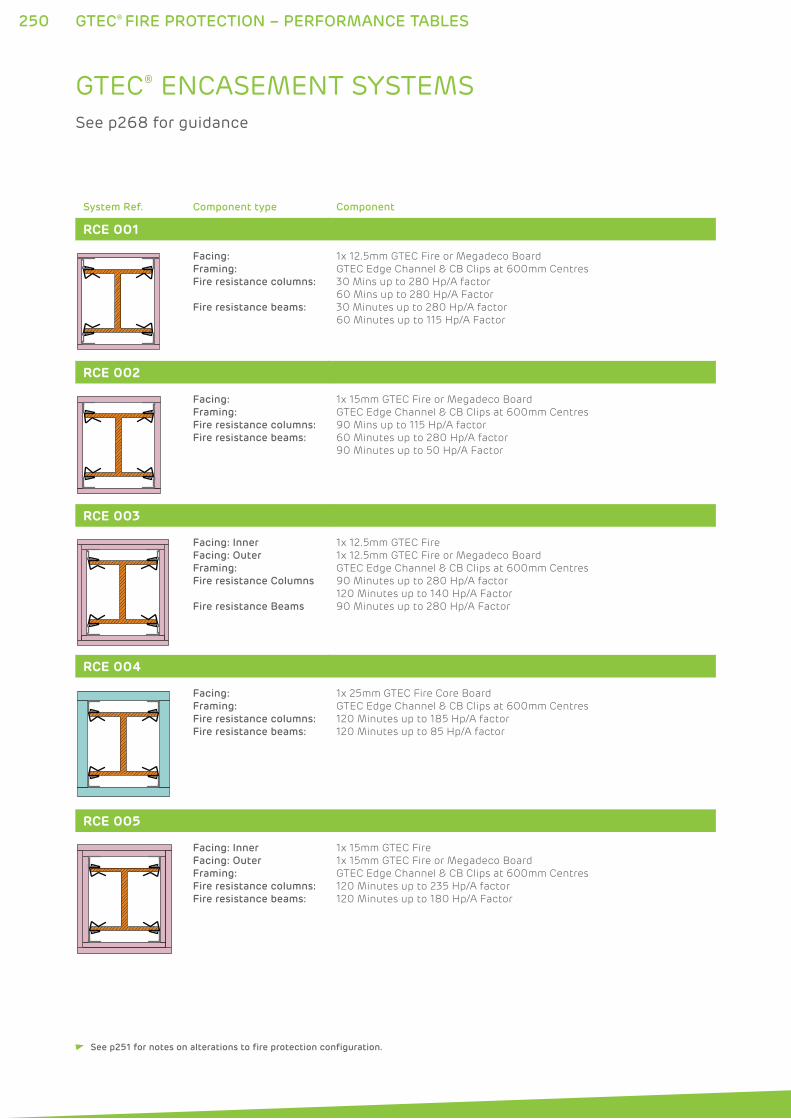
250 GTEC® FIRE PROTECTION – PERFORMANCE TABLES
System Ref. Component type Component
RCE 001
Facing:
Framing:
Fire resistance columns:
Fire resistance beams:
1x 12.5mm GTEC Fire or Megadeco Board
GTEC Edge Channel & CB Clips at 600mm Centres
30 Mins up to 280 Hp/A factor
60 Mins up to 280 Hp/A Factor
30 Minutes up to 280 Hp/A factor
60 Minutes up to 115 Hp/A Factor
RCE 002
Facing:
Framing:
Fire resistance columns:
Fire resistance beams:
1x 15mm GTEC Fire or Megadeco Board
GTEC Edge Channel & CB Clips at 600mm Centres
90 Mins up to 115 Hp/A factor
60 Minutes up to 280 Hp/A factor
90 Minutes up to 50 Hp/A Factor
RCE 003
Facing: Inner
Facing: Outer
Framing:
Fire resistance Columns
Fire resistance Beams
1x 12.5mm GTEC Fire
1x 12.5mm GTEC Fire or Megadeco Board
GTEC Edge Channel & CB Clips at 600mm Centres
90 Minutes up to 280 Hp/A factor
120 Minutes up to 140 Hp/A Factor
90 Minutes up to 280 Hp/A Factor
RCE 004
Facing:
Framing:
Fire resistance columns:
Fire resistance beams:
1x 25mm GTEC Fire Core Board
GTEC Edge Channel & CB Clips at 600mm Centres
120 Minutes up to 185 Hp/A factor
120 Minutes up to 85 Hp/A factor
RCE 005
Facing: Inner
Facing: Outer
Framing:
Fire resistance columns:
Fire resistance beams:
1x 15mm GTEC Fire
1x 15mm GTEC Fire or Megadeco Board
GTEC Edge Channel & CB Clips at 600mm Centres
120 Minutes up to 235 Hp/A factor
120 Minutes up to 180 Hp/A Factor
GTEC® ENCASEMENT SYSTEMS See p268 for guidance
See p251 for notes on alterations to fire protection configuration.
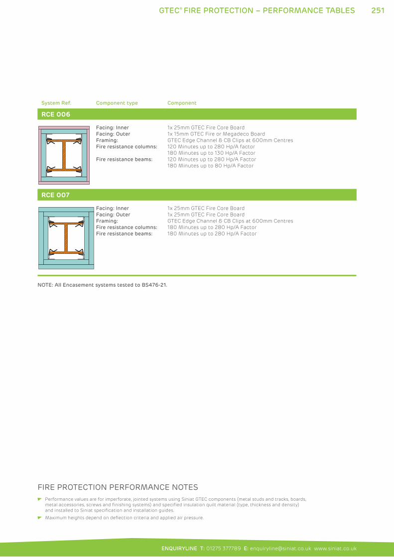
251GTEC® FIRE PROTECTION – PERFORMANCE TABLES
ENQUIRYLINE T: 01275 377789 E: [email protected] www.siniat.co.uk
System Ref. Component type Component
RCE 006
Facing: Inner
Facing: Outer
Framing:
Fire resistance columns:
Fire resistance beams:
1x 25mm GTEC Fire Core Board
1x 15mm GTEC Fire or Megadeco Board
GTEC Edge Channel & CB Clips at 600mm Centres
120 Minutes up to 280 Hp/A factor
180 Minutes up to 130 Hp/A Factor
120 Minutes up to 280 Hp/A Factor
180 Minutes up to 80 Hp/A Factor
RCE 007
Facing: Inner
Facing: Outer
Framing:
Fire resistance columns:
Fire resistance beams:
1x 25mm GTEC Fire Core Board
1x 25mm GTEC Fire Core Board
GTEC Edge Channel & CB Clips at 600mm Centres
180 Minutes up to 280 Hp/A Factor
180 Minutes up to 280 Hp/A Factor
NOTE: All Encasement systems tested to BS476-21.
FIRE PROTECTION PERFORMANCE NOTES Performance values are for imperforate, jointed systems using Siniat GTEC components (metal studs and tracks, boards,
metal accessories, screws and finishing systems) and specified insulation quilt material (type, thickness and density)
and installed to Siniat specification and installation guides.
Maximum heights depend on deflection criteria and applied air pressure.
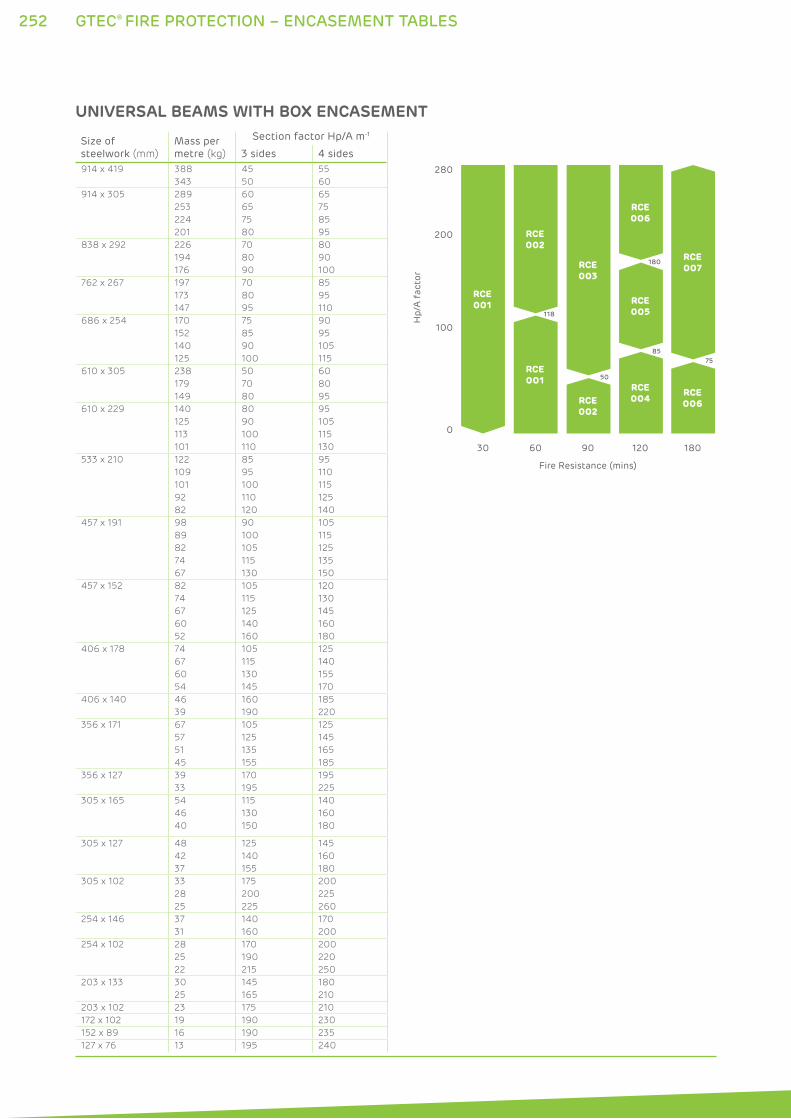
252 GTEC® FIRE PROTECTION – ENCASEMENT TABLES
Size ofsteelwork (mm)
Mass per metre (kg) 3 sides 4 sides
914 x 419 388 45 55
343 50 60
914 x 305 289 60 65
253 65 75
224 75 85
201 80 95
838 x 292 226 70 80
194 80 90
176 90 100
762 x 267 197 70 85
173 80 95
147 95 110
686 x 254 170 75 90
152 85 95
140 90 105
125 100 115
610 x 305 238 50 60
179 70 80
149 80 95
610 x 229 140 80 95
125 90 105
113 100 115
101 110 130
533 x 210 122 85 95
109 95 110
101 100 115
92 110 125
82 120 140
457 x 191 98 90 105
89 100 115
82 105 125
74 115 135
67 130 150
457 x 152 82 105 120
74 115 130
67 125 145
60 140 160
52 160 180
406 x 178 74 105 125
67 115 140
60 130 155
54 145 170
406 x 140 46 160 185
39 190 220
356 x 171 67 105 125
57 125 145
51 135 165
45 155 185
356 x 127 39 170 195
33 195 225
305 x 165 54 115 140
46 130 160
40 150 180
305 x 127 48 125 145
42 140 160
37 155 180
305 x 102 33 175 200
28 200 225
25 225 260
254 x 146 37 140 170
31 160 200
254 x 102 28 170 200
25 190 220
22 215 250
203 x 133 30 145 180
25 165 210
203 x 102 23 175 210
172 x 102 19 190 230
152 x 89 16 190 235
127 x 76 13 195 240
Section factor Hp/A m-1
280
200
100
0H
p/A
fac
tor
30 60 90 120 180
RCE001
RCE002
RCE001
RCE002
RCE006
RCE007RCE
003
RCE004
RCE005
RCE006
Fire Resistance (mins)
118
50
85
180
75
UNIVERSAL BEAMS WITH BOX ENCASEMENT
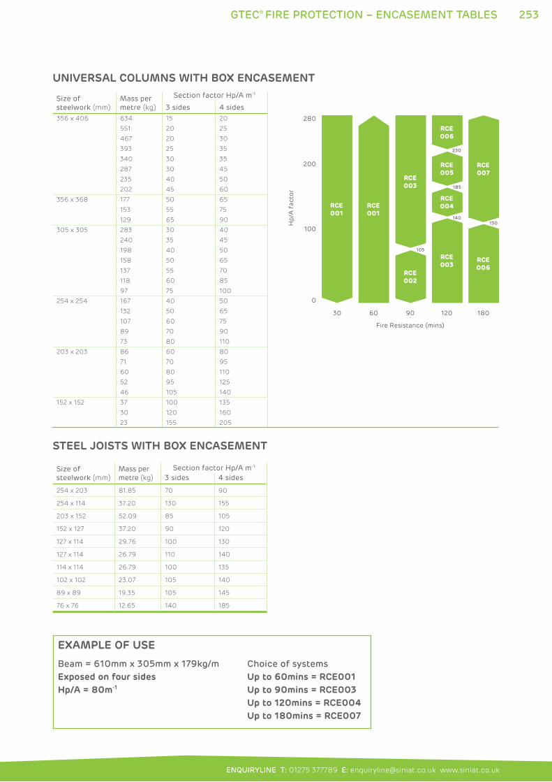
253
ENQUIRYLINE T: 01275 377789 E: [email protected] www.siniat.co.uk
GTEC® FIRE PROTECTION – ENCASEMENT TABLES
Size ofsteelwork (mm)
Mass per metre (kg) 3 sides 4 sides
254 x 203 81.85 70 90
254 x 114 37.20 130 155
203 x 152 52.09 85 105
152 x 127 37.20 90 120
127 x 114 29.76 100 130
127 x 114 26.79 110 140
114 x 114 26.79 100 135
102 x 102 23.07 105 140
89 x 89 19.35 105 145
76 x 76 12.65 140 185
Section factor Hp/A m-1
280
200
100
0H
p/A
fac
tor
30 60 90 120 180
RCE001
RCE001
RCE006
RCE007
RCE003
RCE003
RCE005
RCE004
RCE006
Fire Resistance (mins)
140
230
185
RCE002
105
130
Size ofsteelwork (mm)
Mass per metre (kg) 3 sides 4 sides
356 x 406 634 15 20
551 20 25
467 20 30
393 25 35
340 30 35
287 30 45
235 40 50
202 45 60
356 x 368 177 50 65
153 55 75
129 65 90
305 x 305 283 30 40
240 35 45
198 40 50
158 50 65
137 55 70
118 60 85
97 75 100
254 x 254 167 40 50
132 50 65
107 60 75
89 70 90
73 80 110
203 x 203 86 60 80
71 70 95
60 80 110
52 95 125
46 105 140
152 x 152 37 100 135
30 120 160
23 155 205
Section factor Hp/A m-1
UNIVERSAL COLUMNS WITH BOX ENCASEMENT
STEEL JOISTS WITH BOX ENCASEMENT
Beam = 610mm x 305mm x 179kg/m
Exposed on four sidesHp/A = 80m-1
Choice of systems
Up to 60mins = RCE001Up to 90mins = RCE003Up to 120mins = RCE004Up to 180mins = RCE007
EXAMPLE OF USE
254 GTEC® SHAFTWALL
GTEC® SHAFTWALL SYSTEMSThe GTEC Shaftwall Fire Protection system protects shafts
and voids in multi-storey buildings with a rapid installation
system preventing continuous routes for the spread of fire.
The system uses a non-symmetrical board assembly for full
installation from one side of the shaft, allowing construction in
tight spaces. The frame features friction fit channels to receive
GTEC Fire Core Board and a fixing flange for the installation
of GTEC Fire, Megadeco or Universal Boards ready to finish on
the room side. The shaft side can also be decoratively finished
using GTEC Shaftwall Stairwell systems, this is commonly used
in stairwells.
GTEC Shaftwall Fire Protection can also be used horizontally to
protect the underside of ductwork or provide a ‘lid’ to a shaft.
In horizontal applications, further boards may be needed to
achieve fire performances. Refer to the System Performance
Tables on pages 244 to 249 for full details.
WHERE TO USE: GTEC Shaftwall Systems are used to protect voids in commercial or
public multi-storey buildings and is suitable for most construction types.
FEATURES BENEFITS
System designed to be erected from one side only No scaffolding required
Offers fire protection from both directions Provides up to 120 minutes fire performance
Lightweight friction fit framing system Fast to install with less material costs
Specialised components designed as a system Reliable and easy to specify
Framing includes cavity Allows space for services to run
High strength frame Resists pressure changes likely in deep shafts
and voids
Fully sealed Prevents whistling, dirt accumulation and
ensures fire performance
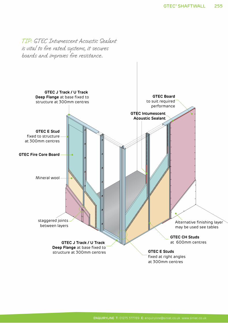
255
ENQUIRYLINE T: 01275 377789 E: [email protected] www.siniat.co.uk
GTEC J Track / U Track Deep Flange at base fixed tostructure at 300mm centres
GTEC J Track / U Track Deep Flange at base fixed tostructure at 300mm centres
GTEC E Studfixed to structure
at 300mm centres
GTEC Fire Core Board
staggered joints between layers
Mineral wool
Alternative finishing layermay be used see tables
GTEC CH Studsat 600mm centres
GTEC E Studsfixed at right angles at 300mm centres
GTEC Boardto suit required
performance
GTEC IntumescentAcoustic Sealant
GTEC® SHAFTWALL
TIP: GTEC Intumescent Acoustic Sealant is vital to fire rated systems, it secures boards and improves fire resistance.
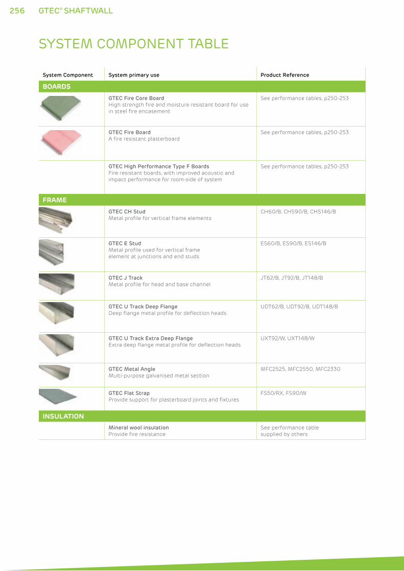
256 GTEC® SHAFTWALL
SYSTEM COMPONENT TABLE
System Component System primary use Product Reference
BOARDS
GTEC Fire Core Board
High strength fire and moisture resistant board for use
in steel fire encasement
See performance tables, p250-253
GTEC Fire Board
A fire resistant plasterboard
See performance tables, p250-253
GTEC High Performance Type F Boards
Fire resistant boards, with improved acoustic and
impact performance for room-side of system
See performance tables, p250-253
FRAME
GTEC CH Stud
Metal profile for vertical frame elements
CH60/B, CHS90/B, CHS146/B
GTEC E Stud
Metal profile used for vertical frame
element at junctions and end studs
ES60/B, ES90/B, ES146/B
GTEC J Track
Metal profile for head and base channel
JT62/B, JT92/B, JT148/B
GTEC U Track Deep Flange
Deep flange metal profile for deflection heads
UDT62/B, UDT92/B, UDT148/B
GTEC U Track Extra Deep Flange
Extra deep flange metal profile for deflection heads
UXT92/W, UXT148/W
GTEC Metal Angle
Multi-purpose galvanised metal section
MFC2525, MFC2550, MFC2330
GTEC Flat Strap
Provide support for plasterboard joints and fixtures
FS50/RX, FS90/W
INSULATION
Mineral wool insulation
Provide fire resistance
See performance table
supplied by others
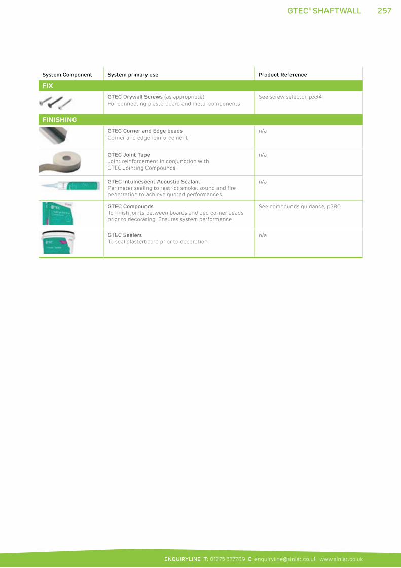
257
ENQUIRYLINE T: 01275 377789 E: [email protected] www.siniat.co.uk
GTEC® SHAFTWALL
System Component System primary use Product Reference
FIX
GTEC Drywall Screws (as appropriate)
For connecting plasterboard and metal components
See screw selector, p334
FINISHING
GTEC Corner and Edge beads
Corner and edge reinforcement
n/a
GTEC Joint Tape
Joint reinforcement in conjunction with
GTEC Jointing Compounds
n/a
GTEC Intumescent Acoustic Sealant
Perimeter sealing to restrict smoke, sound and fire
penetration to achieve quoted performances
n/a
GTEC Compounds
To finish joints between boards and bed corner beads
prior to decorating. Ensures system performance
See compounds guidance, p280
GTEC Sealers
To seal plasterboard prior to decoration
n/a
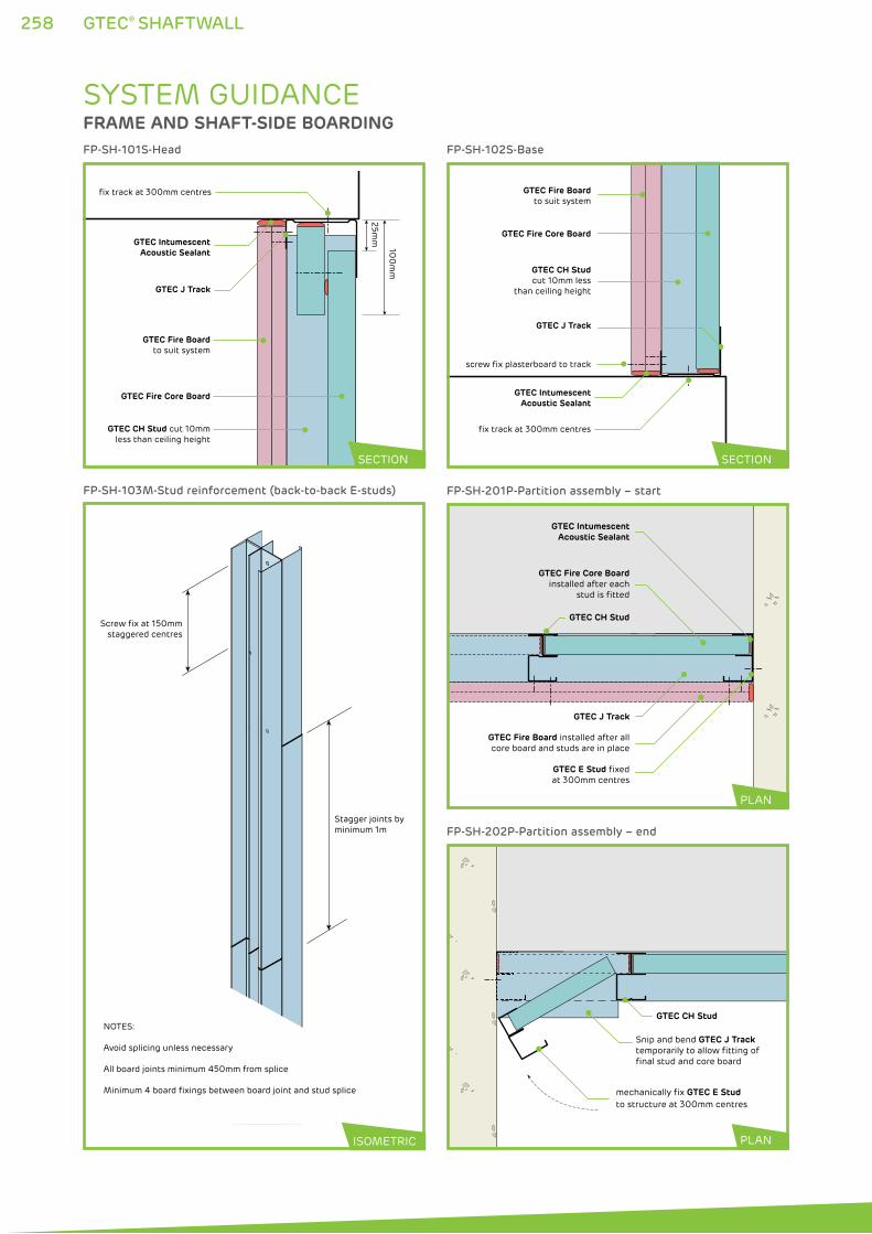
258 GTEC® SHAFTWALL
Snip and bend GTEC J Track temporarily to allow fitting of final stud and core board
mechanically fix GTEC E Stud to structure at 300mm centres
GTEC CH Stud
FP-SH-202P-Partition assembly – end
Screw fix at 150mmstaggered centres
Stagger joints byminimum 1m
NOTES:
Avoid splicing unless necessary
All board joints minimum 450mm from splice
Minimum 4 board fixings between board joint and stud splice
FP-SH-103M-Stud reinforcement (back-to-back E-studs)
GTEC IntumescentAcoustic Sealant
GTEC Fire Board installed after allcore board and studs are in place
GTEC Fire Core Boardinstalled after each
stud is fitted
GTEC J Track
GTEC CH Stud
GTEC E Stud fixedat 300mm centres
FP-SH-201P-Partition assembly – start
PLAN
PLANISOMETRIC
SYSTEM GUIDANCEFRAME AND SHAFT-SIDE BOARDING
25mm
100
mm
GTEC IntumescentAcoustic Sealant
GTEC Fire Core Board
GTEC J Track
GTEC CH Stud cut 10mmless than ceiling height
GTEC Fire Boardto suit system
fix track at 300mm centres
FP-SH-101S-Head
GTEC IntumescentAcoustic Sealant
GTEC Fire Core Board
GTEC CH Studcut 10mm less
than ceiling height
GTEC Fire Boardto suit system
fix track at 300mm centres
screw fix plasterboard to track
GTEC J Track
FP-SH-102S-Base
SECTION SECTION
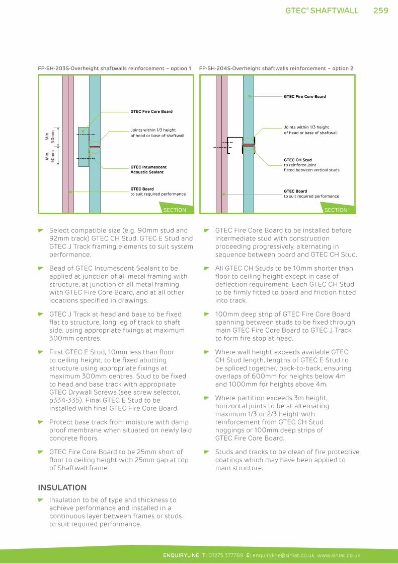
259
ENQUIRYLINE T: 01275 377789 E: [email protected] www.siniat.co.uk
GTEC® SHAFTWALL
INSULATION Insulation to be of type and thickness to
achieve performance and installed in a
continuous layer between frames or studs
to suit required performance.
Select compatible size (e.g. 90mm stud and
92mm track) GTEC CH Stud, GTEC E Stud and
GTEC J Track framing elements to suit system
performance.
Bead of GTEC Intumescent Sealant to be
applied at junction of all metal framing with
structure, at junction of all metal framing
with GTEC Fire Core Board, and at all other
locations specified in drawings.
GTEC J Track at head and base to be fixed
flat to structure, long leg of track to shaft
side, using appropriate fixings at maximum
300mm centres.
First GTEC E Stud, 10mm less than floor
to ceiling height, to be fixed abutting
structure using appropriate fixings at
maximum 300mm centres. Stud to be fixed
to head and base track with appropriate
GTEC Drywall Screws (see screw selector,
p334-335). Final GTEC E Stud to be
installed with final GTEC Fire Core Board.
Protect base track from moisture with damp
proof membrane when situated on newly laid
concrete floors.
GTEC Fire Core Board to be 25mm short of
floor to ceiling height with 25mm gap at top
of Shaftwall frame.
GTEC Fire Core Board to be installed before
intermediate stud with construction
proceeding progressively, alternating in
sequence between board and GTEC CH Stud.
All GTEC CH Studs to be 10mm shorter than
floor to ceiling height except in case of
deflection requirement. Each GTEC CH Stud
to be firmly fitted to board and friction fitted
into track.
100mm deep strip of GTEC Fire Core Board
spanning between studs to be fixed through
main GTEC Fire Core Board to GTEC J Track
to form fire stop at head.
Where wall height exceeds available GTEC
CH Stud length, lengths of GTEC E Stud to
be spliced together, back-to-back, ensuring
overlaps of 600mm for heights below 4m
and 1000mm for heights above 4m.
Where partition exceeds 3m height,
horizontal joints to be at alternating
maximum 1/3 or 2/3 height with
reinforcement from GTEC CH Stud
noggings or 100mm deep strips of
GTEC Fire Core Board.
Studs and tracks to be clean of fire protective
coatings which may have been applied to
main structure.
MIn
.50
mm
M
In.
50m
m
GTEC Fire Core Board
GTEC IntumescentAcoustic Sealant
GTEC Boardto suit required performance
Joints within 1/3 height of head or base of shaftwall
FP-SH-203S-Overheight shaftwalls reinforcement – option 1
GTEC Fire Core Board
GTEC Boardto suit required performance
Joints within 1/3 height of head or base of shaftwall
GTEC CH Studto reinforce joint fitted between vertical studs
FP-SH-204S-Overheight shaftwalls reinforcement – option 2
SECTION SECTION
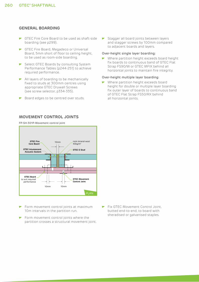
260 GTEC® SHAFTWALL
MOVEMENT CONTROL JOINTS
GTEC Movement Control Joint
GTEC Boardto suit required
performance
GTEC IntumescentAcoustic Sealant
GTEC FireCore Board
rock mineral wool40kg/m3
GTEC E Stud
10mm
10mm
10mm
FP-SH-301P-Movement control joint
PLAN
Form movement control joints at maximum
10m intervals in the partition run.
Form movement control joints where the
partition crosses a structural movement joint.
Fix GTEC Movement Control Joint,
butted end-to-end, to board with
sheradised or galvanised staples.
GTEC Fire Core Board to be used as shaft-side
boarding (see p299).
GTEC Fire Board, Megadeco or Universal
Board, 5mm short of floor to ceiling height,
to be used as room-side boarding.
Select GTEC Boards by consulting System
Performance Tables (p244-251) to achieve
required performance.
All layers of boarding to be mechanically
fixed to studs at 300mm centres using
appropriate GTEC Drywall Screws
(see screw selector, p334-335).
Board edges to be centred over studs.
Stagger all board joints between layers
and stagger screws by 100mm compared
to adjacent boards and layers.
Over-height single layer boarding:
Where partition height exceeds board height
fix boards to continuous band of GTEC Flat
Strap FS90/W or GTEC MFIX behind all
horizontal joints to maintain fire integrity.
Over-height multiple layer boarding:
Where partition height exceeds board
height for double or multiple layer boarding
fix outer layer of boards to continuous band
of GTEC Flat Strap FS50/RX behind
all horizontal joints.
GENERAL BOARDING
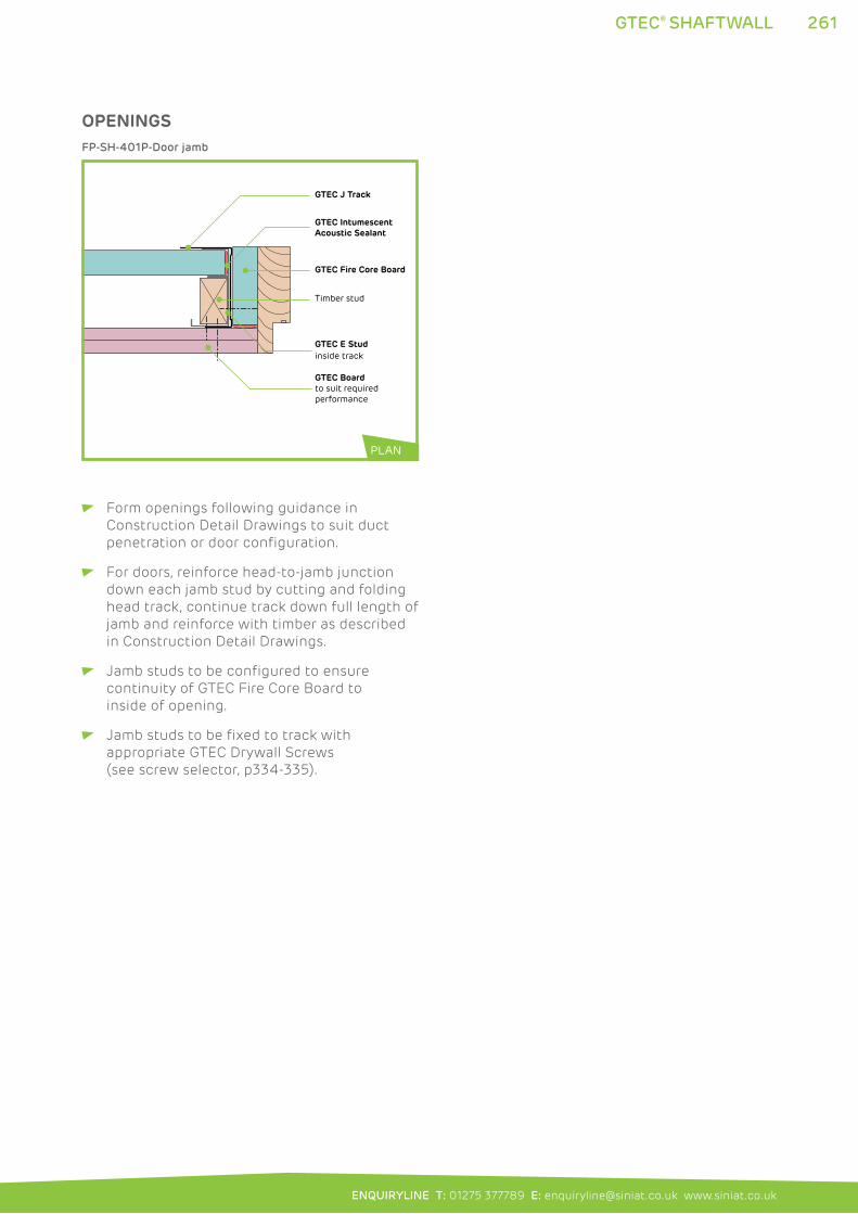
261
ENQUIRYLINE T: 01275 377789 E: [email protected] www.siniat.co.uk
GTEC® SHAFTWALL
OPENINGS
GTEC IntumescentAcoustic Sealant
Timber stud
GTEC E Stud inside track
GTEC J Track
GTEC Boardto suit required performance
GTEC Fire Core Board
FP-SH-401P-Door jamb
Form openings following guidance in
Construction Detail Drawings to suit duct
penetration or door configuration.
For doors, reinforce head-to-jamb junction
down each jamb stud by cutting and folding
head track, continue track down full length of
jamb and reinforce with timber as described
in Construction Detail Drawings.
Jamb studs to be configured to ensure
continuity of GTEC Fire Core Board to
inside of opening.
Jamb studs to be fixed to track with
appropriate GTEC Drywall Screws
(see screw selector, p334-335).
PLAN
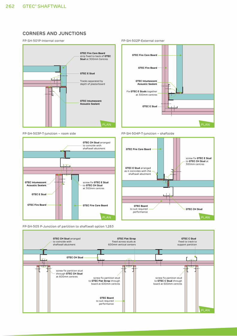
262 GTEC® SHAFTWALL
CORNERS AND JUNCTIONS
GTEC Intumescent Acoustic Sealant
GTEC E Stud
GTEC Fire Core Boardstrip fixed to back of GTEC Stud at 300mm Centres
Tracks separated bydepth of plasterboard
FP-SH-501P-Internal corner
GTEC IntumescentAcoustic Sealant
GTEC E Stud
GTEC Fire Board GTEC Fire Core Board
GTEC CH Stud arrangedto coincide with shaftwall abutment
screw fix GTEC E Stud to GTEC CH Stud at 300mm centres
FP-SH-503P-T-junction – room side
screw fix partition stud to GTEC C Stud through
board at 600mm centres
GTEC C Stud fixed to track to
support partition
GTEC CH Stud
GTEC Flat Strapfixed across studs at
600mm vertical centers
screw fix partition stud to GTEC Flat Strap through
board at 600mm centres
GTEC Boardto suit required
performance
GTEC CH Stud arrangedto coincide withshaftwall abutment
screw fix partition stud through GTEC CH Stud at 600mm centres
FP-SH-505 P-Junction of partition to shaftwall option 1,2&3
GTEC Intumescent Acoustic Sealant
GTEC Fire Core Board
GTEC Fire Board
GTEC E Stud
Fix GTEC E Studs together at 300mm centres
FP-SH-502P-External corner
GTEC Boardto suit required
performance
GTEC E Stud arranged as it coincides with the
shaftwall abutment
GTEC CH Stud
GTEC Fire Core Board
screw fix GTEC E Stud to GTEC CH Stud at 300mm centres
FP-SH-504P-T-junction – shaftside
PLAN
PLAN
PLAN
PLAN
PLAN
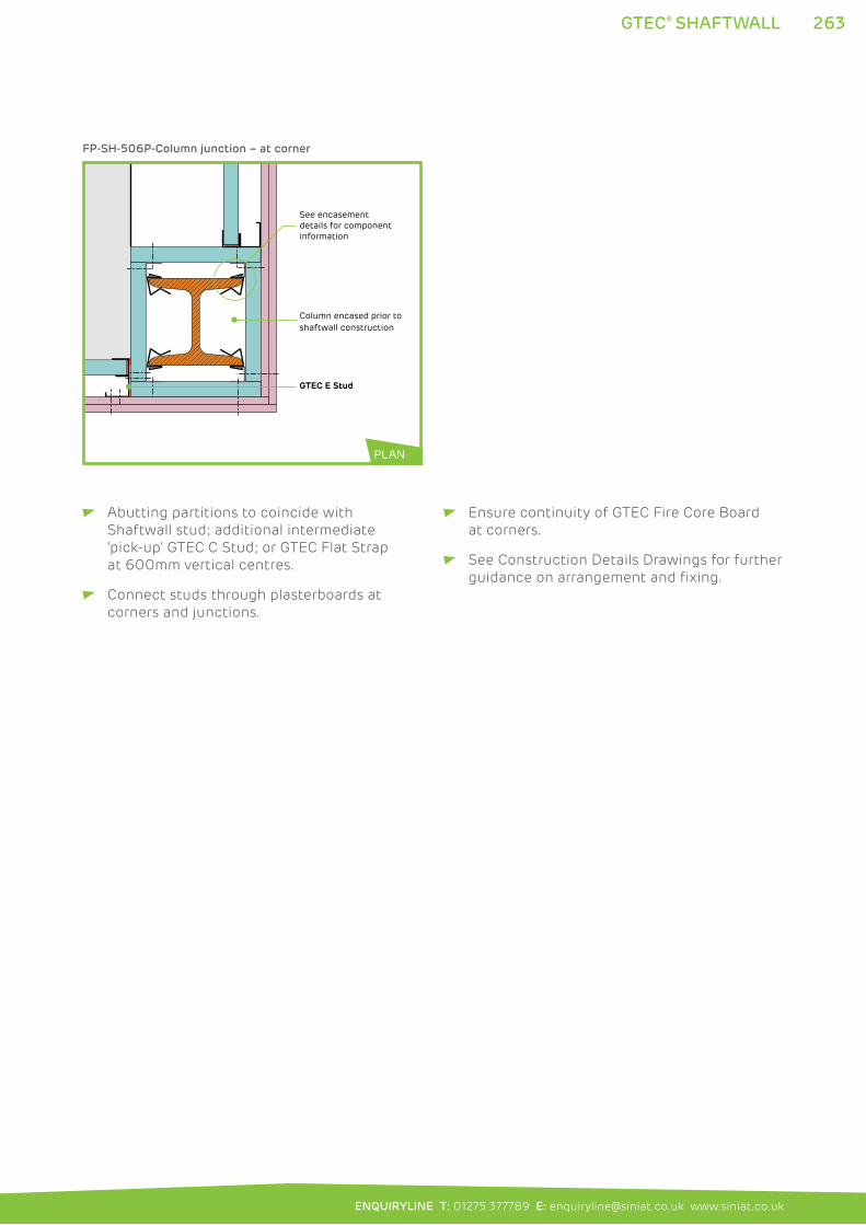
263
ENQUIRYLINE T: 01275 377789 E: [email protected] www.siniat.co.uk
GTEC® SHAFTWALL
Column encased prior toshaftwall construction
GTEC E Stud
See encasement details for component information
FP-SH-506P-Column junction – at corner
Abutting partitions to coincide with
Shaftwall stud; additional intermediate
‘pick-up’ GTEC C Stud; or GTEC Flat Strap
at 600mm vertical centres.
Connect studs through plasterboards at
corners and junctions.
Ensure continuity of GTEC Fire Core Board
at corners.
See Construction Details Drawings for further
guidance on arrangement and fixing.
PLAN
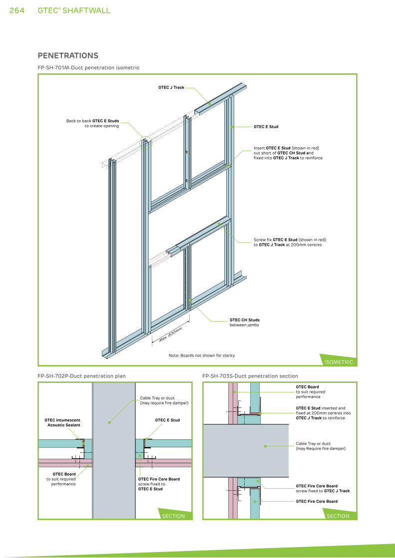
264 GTEC® SHAFTWALL
Note: Boards not shown for clarity
GTEC CH Studsbetween jambs
Back to back GTEC E Studsto create opening GTEC E Stud
Insert GTEC E Stud (shown in red)cut short of GTEC CH Stud and fixed into GTEC J Track to reinforce
Screw fix GTEC E Stud (shown in red)to GTEC J Track at 200mm centres
GTEC J Track
Max. 600mm
FP-SH-701M-Duct penetration isometric
PENETRATIONS
ISOMETRIC
GTEC Fire Core Board screw fixed toGTEC E Stud
GTEC Boardto suit required
performance
GTEC E Stud
Cable Tray or duct (may require fire damper)
GTEC IntumescentAcoustic Sealant
FP-SH-702P-Duct penetration plan
GTEC Fire Core Board
GTEC Fire Core Board screw fixed to GTEC J Track
GTEC Boardto suit required performance
GTEC E Stud inserted and fixed at 200mm centres into GTEC J Track to reinforce
Cable Tray or duct (may Require fire damper)
FP-SH-703S-Duct penetration section
SECTION SECTION
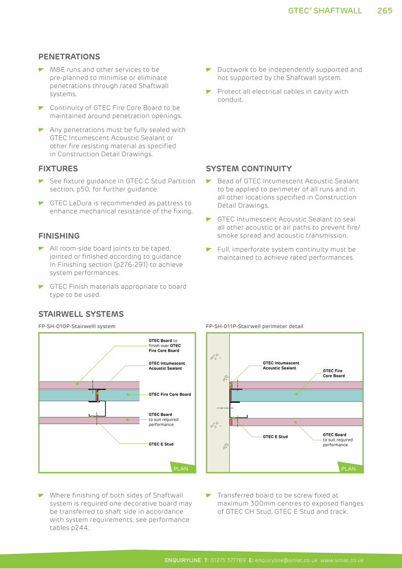
265
ENQUIRYLINE T: 01275 377789 E: [email protected] www.siniat.co.uk
GTEC® SHAFTWALL
M&E runs and other services to be
pre-planned to minimise or eliminate
penetrations through rated Shaftwall
systems.
Continuity of GTEC Fire Core Board to be
maintained around penetration openings.
Any penetrations must be fully sealed with
GTEC Intumescent Acoustic Sealant or
other fire resisting material as specified
in Construction Detail Drawings.
Ductwork to be independently supported and
not supported by the Shaftwall system.
Protect all electrical cables in cavity with
conduit.
FIXTURES See fixture guidance in GTEC C Stud Partition
section, p50, for further guidance.
GTEC LaDura is recommended as pattress to
enhance mechanical resistance of the fixing.
FINISHING All room-side board joints to be taped,
jointed or finished according to guidance
in Finishing section (p276-291) to achieve
system performances.
GTEC Finish materials appropriate to board
type to be used.
SYSTEM CONTINUITY Bead of GTEC Intumescent Acoustic Sealant
to be applied to perimeter of all runs and in
all other locations specified in Construction
Detail Drawings.
GTEC Intumescent Acoustic Sealant to seal
all other acoustic or air paths to prevent fire/
smoke spread and acoustic transmission.
Full, imperforate system continuity must be
maintained to achieve rated performances.
PENETRATIONS
Where finishing of both sides of Shaftwall
system is required one decorative board may
be transferred to shaft side in accordance
with system requirements, see performance
tables p244.
Transferred board to be screw fixed at
maximum 300mm centres to exposed flanges
of GTEC CH Stud, GTEC E Stud and track.
STAIRWELL SYSTEMS
GTEC Fire Core Board
GTEC E Stud
GTEC Intumescent Acoustic Sealant
GTEC Boardto suit required performance
GTEC Board to finish over GTEC Fire Core Board
FP-SH-010P-Stairwelll system
GTEC Fire Core Board
GTEC E Stud
GTEC Intumescent Acoustic Sealant
GTEC Boardto suit required performance
FP-SH-011P-Stairwell perimeter detail
PLANPLAN
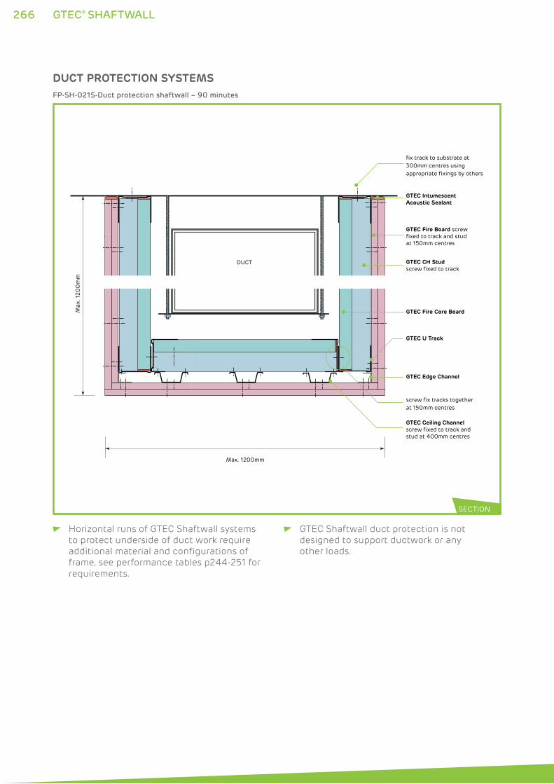
266 GTEC® SHAFTWALL
Horizontal runs of GTEC Shaftwall systems
to protect underside of duct work require
additional material and configurations of
frame, see performance tables p244-251 for
requirements.
GTEC Shaftwall duct protection is not
designed to support ductwork or any
other loads.
GTEC U Track
GTEC CH Stud screw fixed to track
DUCT
GTEC Intumescent Acoustic Sealant
fix track to substrate at 300mm centres using appropriate fixings by others
screw fix tracks together at 150mm centres
Max. 1200mm
Max
. 120
0m
m
GTEC Fire Core Board
GTEC Fire Board screw fixed to track and studat 150mm centres
GTEC Ceiling Channelscrew fixed to track and stud at 400mm centres
GTEC Edge Channel
FP-SH-021S-Duct protection shaftwall – 90 minutes
SECTION
DUCT PROTECTION SYSTEMS
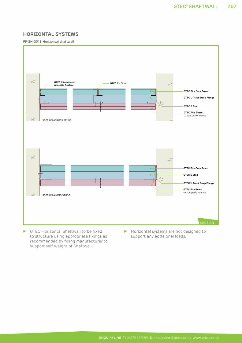
267
ENQUIRYLINE T: 01275 377789 E: [email protected] www.siniat.co.uk
GTEC® SHAFTWALL
GTEC Horizontal Shaftwall to be fixed
to structure using appropriate fixings as
recommended by fixing manufacturer to
support self-weight of Shaftwall.
Horizontal systems are not designed to
support any additional loads.
GTEC Fire Core Board
GTEC E Stud
GTEC Intumescent Acoustic Sealant
GTEC CH Stud
GTEC Fire Boardto suit performance
GTEC Fire Core Board
GTEC E Stud
GTEC Fire Boardto suit performance
GTEC U Track Deep Flange
GTEC U Track Deep Flange
SECTION ALONG STUDS
SECTION ACROSS STUDS
FP-SH-031S-Horizontal shaftwall
HORIZONTAL SYSTEMS
SECTION
268 GTEC® ENCASEMENT
GTEC® ENCASEMENT SYSTEMSThe GTEC Encasement Fire Protection system provides high levels of
fire resistance to structural I-section columns and beams, delaying the
loss of strength in steel which occurs at temperatures over 550°C.
The system uses push-fit GTEC CB Clips to secure GTEC Edge Channel
to the steel. GTEC Fire Core Boards, Fire Boards, and other high
performance boards as detailed in the performance tables, are fixed
to the edge channel to protect columns and beams. Excellent fire
performance is achieved by holding the boards off the columns on a
strong metal frame.
WHERE TO USE: The system is used in commercial multi-storey construction to ensure
structural safety during fire. The range of impact resistant boards
compatible with the system enables use in high traffic areas.
FEATURES BENEFITS
Uses GTEC Fire Board Economical and effective
Uses GTEC Fire Core Board Fewer board layers required
Fully tested Allows use of Hp/A factors, giving performance
to a range of column and beam dimensions
Fully dry installation Efficient to install
Friction fit frame installation Efficient to install
Allows differential movement during fire
Simple frame design Requires no specialist equipment
Plasterboard finish Flat, easy to decorate, surface. Suitable for use
with GTEC Partitions, Ceilings and Linings
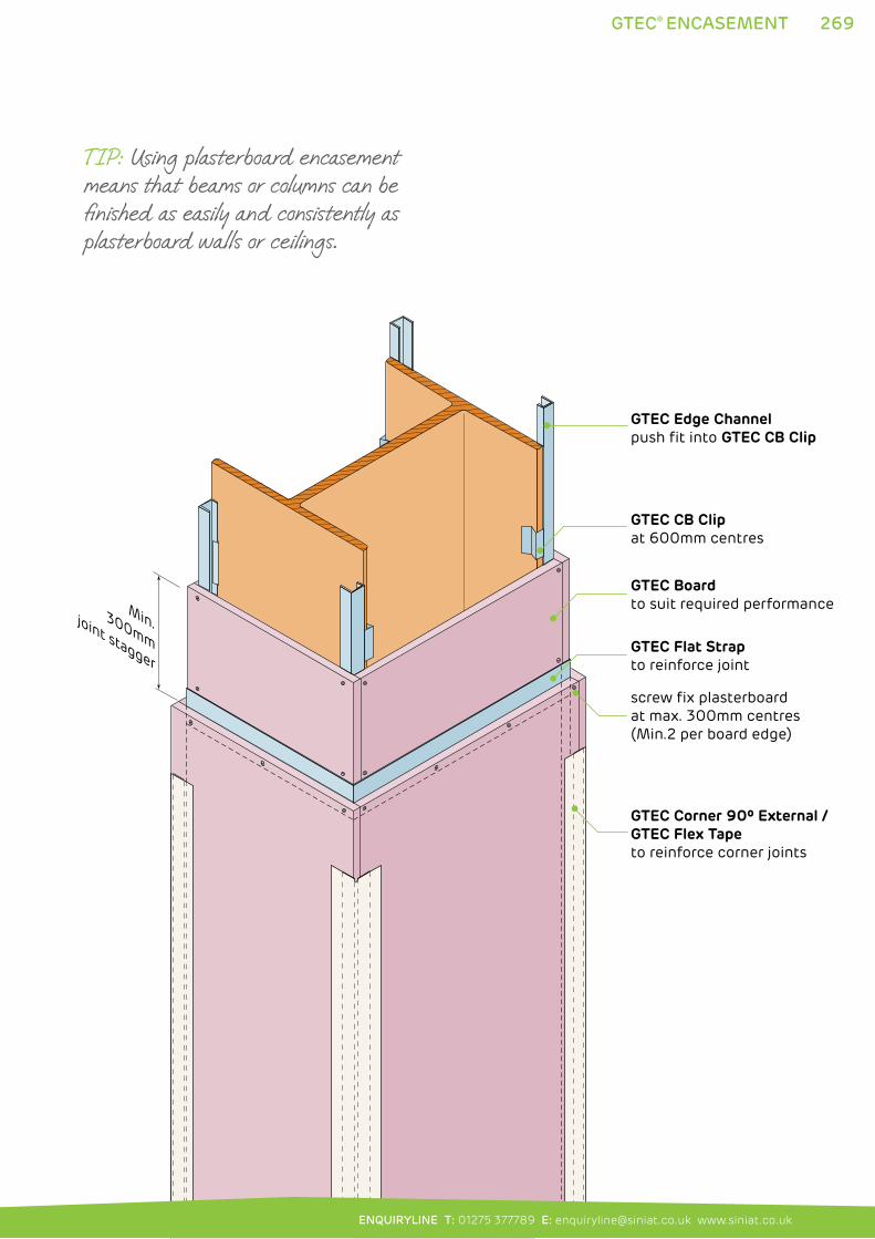
screw fix plasterboard at max. 300mm centres (Min.2 per board edge)
GTEC Boardto suit required performance
GTEC CB Clipat 600mm centres
GTEC Flat Strapto reinforce joint
GTEC Corner 90º External /GTEC Flex Tape to reinforce corner joints
GTEC Edge Channelpush fit into GTEC CB Clip
Min. 300mmjoint stagger
269
ENQUIRYLINE T: 01275 377789 E: [email protected] www.siniat.co.uk
GTEC® ENCASEMENT
TIP: Using plasterboard encasement means that beams or columns can be finished as easily and consistently as plasterboard walls or ceilings.
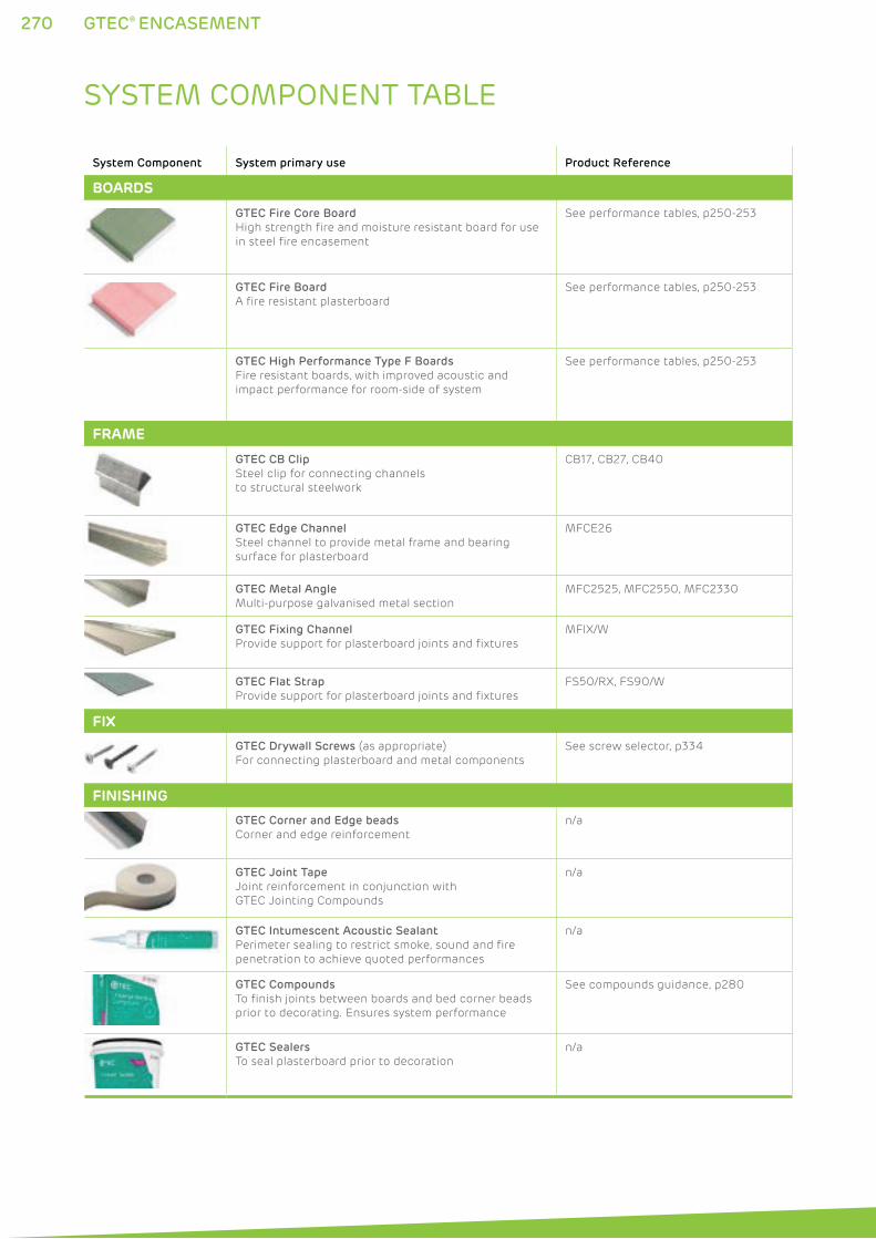
270 GTEC® ENCASEMENT
SYSTEM COMPONENT TABLE
System Component System primary use Product Reference
BOARDS
GTEC Fire Core Board
High strength fire and moisture resistant board for use
in steel fire encasement
See performance tables, p250-253
GTEC Fire Board
A fire resistant plasterboard
See performance tables, p250-253
GTEC High Performance Type F Boards
Fire resistant boards, with improved acoustic and
impact performance for room-side of system
See performance tables, p250-253
FRAME
GTEC CB Clip
Steel clip for connecting channels
to structural steelwork
CB17, CB27, CB40
GTEC Edge Channel
Steel channel to provide metal frame and bearing
surface for plasterboard
MFCE26
GTEC Metal Angle
Multi-purpose galvanised metal section
MFC2525, MFC2550, MFC2330
GTEC Fixing Channel
Provide support for plasterboard joints and fixtures
MFIX/W
GTEC Flat Strap
Provide support for plasterboard joints and fixtures
FS50/RX, FS90/W
FIX
GTEC Drywall Screws (as appropriate)
For connecting plasterboard and metal components
See screw selector, p334
FINISHING
GTEC Corner and Edge beads
Corner and edge reinforcement
n/a
GTEC Joint Tape
Joint reinforcement in conjunction with
GTEC Jointing Compounds
n/a
GTEC Intumescent Acoustic Sealant
Perimeter sealing to restrict smoke, sound and fire
penetration to achieve quoted performances
n/a
GTEC Compounds
To finish joints between boards and bed corner beads
prior to decorating. Ensures system performance
See compounds guidance, p280
GTEC Sealers
To seal plasterboard prior to decoration
n/a
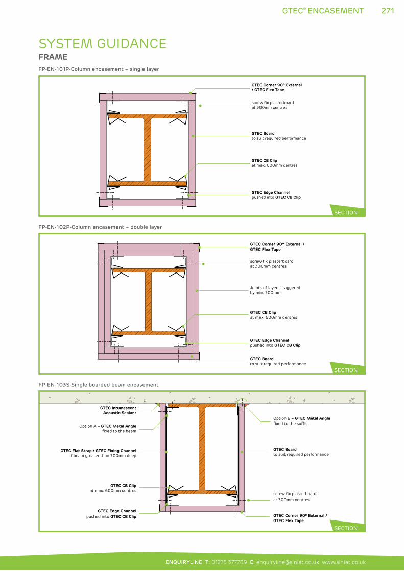
271
ENQUIRYLINE T: 01275 377789 E: [email protected] www.siniat.co.uk
GTEC® ENCASEMENT
SYSTEM GUIDANCEFRAME
GTEC Corner 90º External / GTEC Flex Tape
screw fix plasterboard at 300mm centres
GTEC Boardto suit required performance
GTEC CB Clipat max. 600mm centres
GTEC Edge Channelpushed into GTEC CB Clip
FP-EN-101P-Column encasement – single layer
GTEC Corner 90º External /GTEC Flex Tape
screw fix plasterboard at 300mm centres
Joints of layers staggered by min. 300mm
GTEC Boardto suit required performance
GTEC CB Clipat max. 600mm centres
GTEC Edge Channelpushed into GTEC CB Clip
FP-EN-102P-Column encasement – double layer
GTEC Corner 90º External /GTEC Flex Tape
screw fix plasterboard at 300mm centres
GTEC Boardto suit required performance
GTEC CB Clipat max. 600mm centres
GTEC Edge Channelpushed into GTEC CB Clip
GTEC Flat Strap / GTEC Fixing Channelif beam greater than 300mm deep
Option B – GTEC Metal Anglefixed to the soffit
GTEC IntumescentAcoustic Sealant
Option A – GTEC Metal Angle fixed to the beam
FP-EN-103S-Single boarded beam encasement
SECTION
SECTION
SECTION
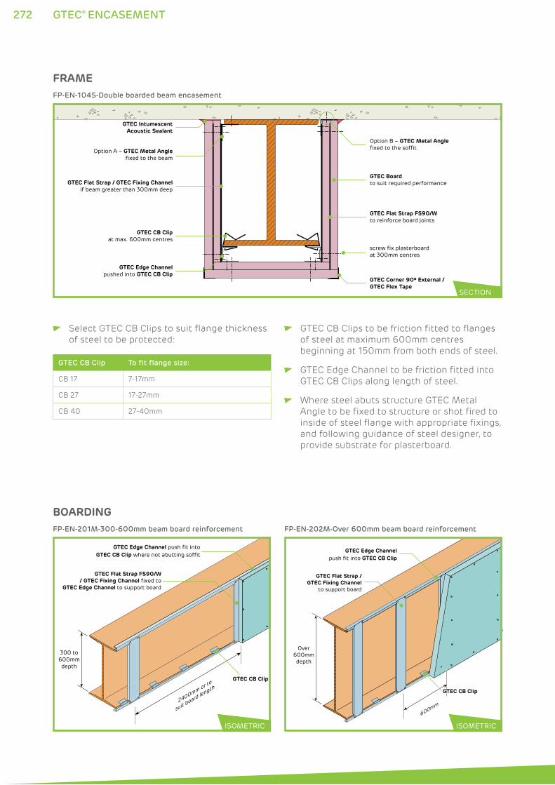
272 GTEC® ENCASEMENT
FRAME
GTEC Corner 90º External /GTEC Flex Tape
screw fix plasterboard at 300mm centres
GTEC Boardto suit required performance
GTEC CB Clipat max. 600mm centres
GTEC Edge Channelpushed into GTEC CB Clip
GTEC IntumescentAcoustic Sealant
Option A – GTEC Metal Angle fixed to the beam
Option B – GTEC Metal Anglefixed to the soffit
GTEC Flat Strap / GTEC Fixing Channelif beam greater than 300mm deep
GTEC Flat Strap FS90/Wto reinforce board joints
FP-EN-104S-Double boarded beam encasement
SECTION
Select GTEC CB Clips to suit flange thickness
of steel to be protected:
GTEC CB Clip To fit flange size:
CB 17 7-17mm
CB 27 17-27mm
CB 40 27-40mm
GTEC CB Clips to be friction fitted to flanges
of steel at maximum 600mm centres
beginning at 150mm from both ends of steel.
GTEC Edge Channel to be friction fitted into
GTEC CB Clips along length of steel.
Where steel abuts structure GTEC Metal
Angle to be fixed to structure or shot fired to
inside of steel flange with appropriate fixings,
and following guidance of steel designer, to
provide substrate for plasterboard.
300 to600mmdepth
2400mm or to
suit board length
GTEC Flat Strap FS90/W/ GTEC Fixing Channel fixed to
GTEC Edge Channel to support board
GTEC CB Clip
GTEC Edge Channel push fit intoGTEC CB Clip where not abutting soffit
FP-EN-201M-300-600mm beam board reinforcement
600mm
Over600mmdepth
GTEC Flat Strap /GTEC Fixing Channel
to support board
GTEC CB Clip
GTEC Edge Channelpush fit into GTEC CB Clip
FP-EN-202M-Over 600mm beam board reinforcement
BOARDING
ISOMETRIC ISOMETRIC
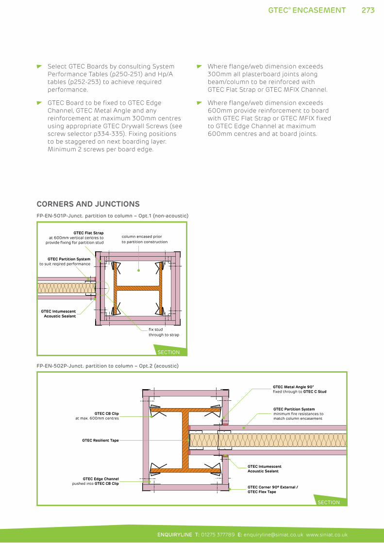
273
ENQUIRYLINE T: 01275 377789 E: [email protected] www.siniat.co.uk
GTEC® ENCASEMENT
Select GTEC Boards by consulting System
Performance Tables (p250-251) and Hp/A
tables (p252-253) to achieve required
performance.
GTEC Board to be fixed to GTEC Edge
Channel, GTEC Metal Angle and any
reinforcement at maximum 300mm centres
using appropriate GTEC Drywall Screws (see
screw selector p334-335). Fixing positions
to be staggered on next boarding layer.
Minimum 2 screws per board edge.
Where flange/web dimension exceeds
300mm all plasterboard joints along
beam/column to be reinforced with
GTEC Flat Strap or GTEC MFIX Channel.
Where flange/web dimension exceeds
600mm provide reinforcement to board
with GTEC Flat Strap or GTEC MFIX fixed
to GTEC Edge Channel at maximum
600mm centres and at board joints.
column encased prior to partition construction
fix stud through to strap
GTEC IntumescentAcoustic Sealant
GTEC Partition Systemto suit reqired performance
GTEC Flat Strapat 600mm vertical centres to
provide fixing for partition stud
FP-EN-501P-Junct. partition to column – Opt.1 (non-acoustic)
GTEC Corner 90º External /GTEC Flex Tape
GTEC CB Clipat max. 600mm centres
GTEC Edge Channelpushed into GTEC CB Clip
GTEC IntumescentAcoustic Sealant
GTEC Partition Systemminimum fire resistances to match column encasement
GTEC Metal Angle 90°fixed through to GTEC C Stud
GTEC Resilient Tape
FP-EN-502P-Junct. partition to column – Opt.2 (acoustic)
SECTION
SECTION
CORNERS AND JUNCTIONS
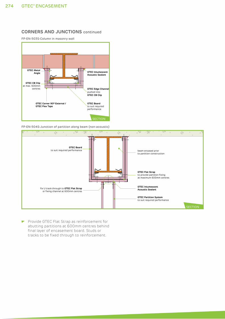
274 GTEC® ENCASEMENT
GTEC Corner 90º External /GTEC Flex Tape
GTEC Boardto suit required performance
GTEC CB Clipat max. 600mm
centres GTEC Edge Channelpushed into GTEC CB Clip
GTEC Intumescent Acoustic Sealant
GTEC MetalAngle
FP-EN-503S-Column in masonry wall
GTEC Boardto suit required performance
GTEC Intumescent Acoustic Sealant
GTEC Partition Systemto suit required performance
fix U track through to GTEC Flat Strap or fixing channel at 600mm centres
beam encased prior to partition construction
GTEC Flat Strapto provide partition fixing at maximum 600mm centres
FP-EN-504S-Junction of partition along beam (non-acoustic)
SECTION
SECTION
CORNERS AND JUNCTIONS continued
Provide GTEC Flat Strap as reinforcement for
abutting partitions at 600mm centres behind
final layer of encasement board. Studs or
tracks to be fixed through to reinforcement.
275
ENQUIRYLINE T: 01275 377789 E: [email protected] www.siniat.co.uk
GTEC® ENCASEMENT
PENETRATIONS Penetrations must not be made through
GTEC Encasement systems.
HEAD DEFLECTION GTEC Encasement systems are designed
to move with beam deflection. Partitions
meeting beams liable to deflection to be
detailed according to guidance in GTEC C
Stud system guidance (see p61).
FIXTURES Fixtures to be supported by structure and not
supported by GTEC Encasement systems.
FINISHING All corners to be reinforced with
GTEC Corner 90.
All board joints to be taped, jointed
or finished according to guidance
in Finishing section (p276-291) to
achieve system performances.
GTEC Finish materials appropriate
to board type to be used.
SYSTEM CONTINUITY Bead of GTEC Intumescent Acoustic Sealant
to be applied to perimeter of all runs and in
all other locations specified in Construction
Detail Drawings.
GTEC Intumescent Acoustic Sealant to seal
all other acoustic or air paths to prevent fire/
smoke spread and acoustic transmission.
Full, imperforate system continuity must be
maintained to achieve rated performances.

GTEC® FINISHING276
277
ENQUIRYLINE T: 01275 377789 E: [email protected] www.siniat.co.uk
GTEC Taping and Jointing 278
Alternative finishing methods 284
GTEC Cove 288
GTEC Taping and Jointing provides a finish to joints between GTEC boards creating a continuous, fire resistant and easy to decorate surface. Skimming can achieve similar results but is a more labour and time intensive method. Tiling GTEC moisture and wet area GTEC boards can achieve exceptionally high levels of water resistance.
GTEC Cove is a decorative gypsum element used to finish the junction between partition and ceiling.
FINISHING
277
278 GTEC® TAPING AND JOINTING
GTEC® TAPING AND JOINTINGGTEC drywall systems require taping and jointing to complete
the wall surface, reinforce joints to prevent cracking, and
ensure fire and sound performances are achieved.
GTEC Taping and Jointing products use limited combustibility,
gypsum and limestone based compounds which secure the
fire rating of the system. These are reinforced with paper tape
or corner beads to create a smooth, durable surface, ready for
decoration. Two and three stage processes are available using
the correct GTEC Finish products to provide options on site and
different setting times.
Water resistant compounds and finishing accessories are
available for GTEC Aqua Board. The GTEC Deco compound range
complements the use of GTEC Megadeco for direct decoration.
WHERE TO USE: Taping and jointing are suitable for large surface areas
where speed and ease of application can greatly reduce
installation cost and drying time.
FEATURES BENEFITS
Applied to low surface areas Quicker than a full plaster skim with less drying
out time
Can be used with automatic taping tools Flexible, high speed application
Can be hand applied Versatile enough to suit any job
Wide product range Suitable for different applications and needs
Gypsum/limestone finish Excellent finish quality with limited
combustibility
Two and three stage processes Provides a range of speed and product options
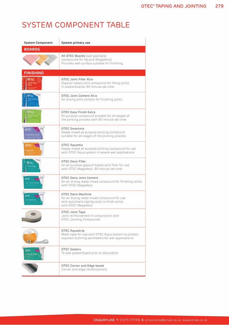
279
ENQUIRYLINE T: 01275 377789 E: [email protected] www.siniat.co.uk
GTEC® TAPING AND JOINTING
System Component System primary use
BOARDS
All GTEC Boards (see specialist
compounds for Aqua & Megadeco)
Provides wall surface suitable for finishing.
FINISHING
GTEC Joint Filler Xtra
Gypsum based joint compound for filling joints
in plasterboards, 90 minute set time
GTEC Joint Cement Xtra
Air-drying joint cement for finishing joints
GTEC Easy Finish Extra
All purpose compound suitable for all stages of
the jointing process with 90 minute set time
GTEC Smartmix
Ready mixed all purpose jointing compound
suitable for all stages of the jointing process
GTEC Aquamix
Ready mixed all purpose jointing compound for use
with GTEC Aqua system in severe wet applications
GTEC Deco Filler
An all purpose gypsum based joint filler for use
with GTEC Megadeco. 90 minute set time
GTEC Deco Joint Cement
An air drying ready mixed compound for finishing joints
with GTEC Megadeco
GTEC Deco Machine
An air drying ready mixed compound for use
with automatic taping tools to finish joints
with GTEC Megadeco
GTEC Joint Tape
Joint reinforcement in conjunction with
GTEC Jointing Compounds
GTEC Aquastrip
Mesh tape for use with GTEC Aqua system to protect
exposed drylining perimeters for wet applications
GTEC Sealers
To seal plasterboard prior to decoration
GTEC Corner and Edge beads
Corner and edge reinforcement
SYSTEM COMPONENT TABLE
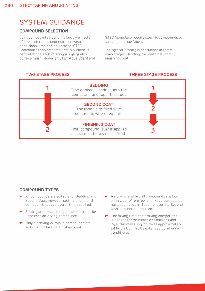
280 GTEC® TAPING AND JOINTING
SYSTEM GUIDANCE
Joint compound selection is largely a matter
of site preference, depending on weather
conditions, time and equipment. GTEC
Compounds can be combined in numerous
permutations each offering a high quality
surface finish. However, GTEC Aqua Board and
GTEC Megadeco require specific compounds to
suit their unique facers.
Taping and jointing is conducted in three
main stages: Bedding; Second Coat; and
Finishing Coat.
All compounds are suitable for Bedding and
Second Coat, however, setting and hybrid
compounds reduce overall time required.
Setting and hybrid compounds must not be
used over air-drying compounds.
Only air-drying or hybrid compounds are
suitable for the final finishing coat.
Air-drying and hybrid compounds are low
shrinkage. Where low shrinkage compounds
have been used in Bedding layer the Second
Coat may not be required.
The drying time of air-drying compounds
is dependent on climatic conditions and
layer thickness. Drying takes approximately
24 hours but may be extended by adverse
conditions.
COMPOUND SELECTION
COMPOUND TYPES
THREE STAGE PROCESS
2
2 3
11BEDDING
Tape or bead is bedded into the
compound and taper filled out
SECOND COATThe taper is re-filled with
compound where required
FINISHING COATFinal compound layer is applied
and sanded for a smooth finish
TWO STAGE PROCESS
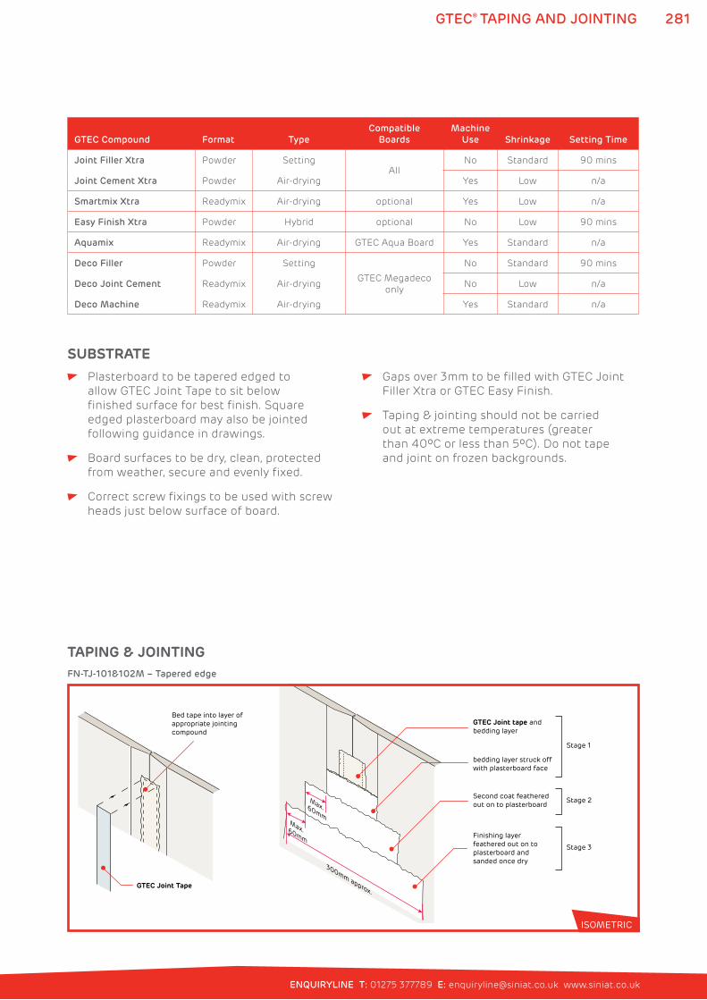
281
ENQUIRYLINE T: 01275 377789 E: [email protected] www.siniat.co.uk
GTEC® TAPING AND JOINTING
Plasterboard to be tapered edged to
allow GTEC Joint Tape to sit below
finished surface for best finish. Square
edged plasterboard may also be jointed
following guidance in drawings.
Board surfaces to be dry, clean, protected
from weather, secure and evenly fixed.
Correct screw fixings to be used with screw
heads just below surface of board.
Gaps over 3mm to be filled with GTEC Joint
Filler Xtra or GTEC Easy Finish.
Taping & jointing should not be carried
out at extreme temperatures (greater
than 40ºC or less than 5ºC). Do not tape
and joint on frozen backgrounds.
SUBSTRATE
GTEC Compound Format Type
Compatible
Boards
Machine
Use Shrinkage Setting Time
Joint Filler Xtra Powder SettingAll
No Standard 90 mins
Joint Cement Xtra Powder Air-drying Yes Low n/a
Smartmix Xtra Readymix Air-drying optional Yes Low n/a
Easy Finish Xtra Powder Hybrid optional No Low 90 mins
Aquamix Readymix Air-drying GTEC Aqua Board Yes Standard n/a
Deco Filler Powder Setting
GTEC Megadeco
only
No Standard 90 mins
Deco Joint Cement Readymix Air-drying No Low n/a
Deco Machine Readymix Air-drying Yes Standard n/a
TAPING & JOINTING
300mm approx.
Max. 60mm
Max.60mm
GTEC Joint Tape
Bed tape into layer of appropriate jointing compound
GTEC Joint tape and bedding layer
bedding layer struck off with plasterboard face
Second coat featheredout on to plasterboard
Finishing layer feathered out on to plasterboard and sanded once dry
Stage 1
Stage 2
Stage 3
FN-TJ-101&102M – Tapered edge
ISOMETRIC
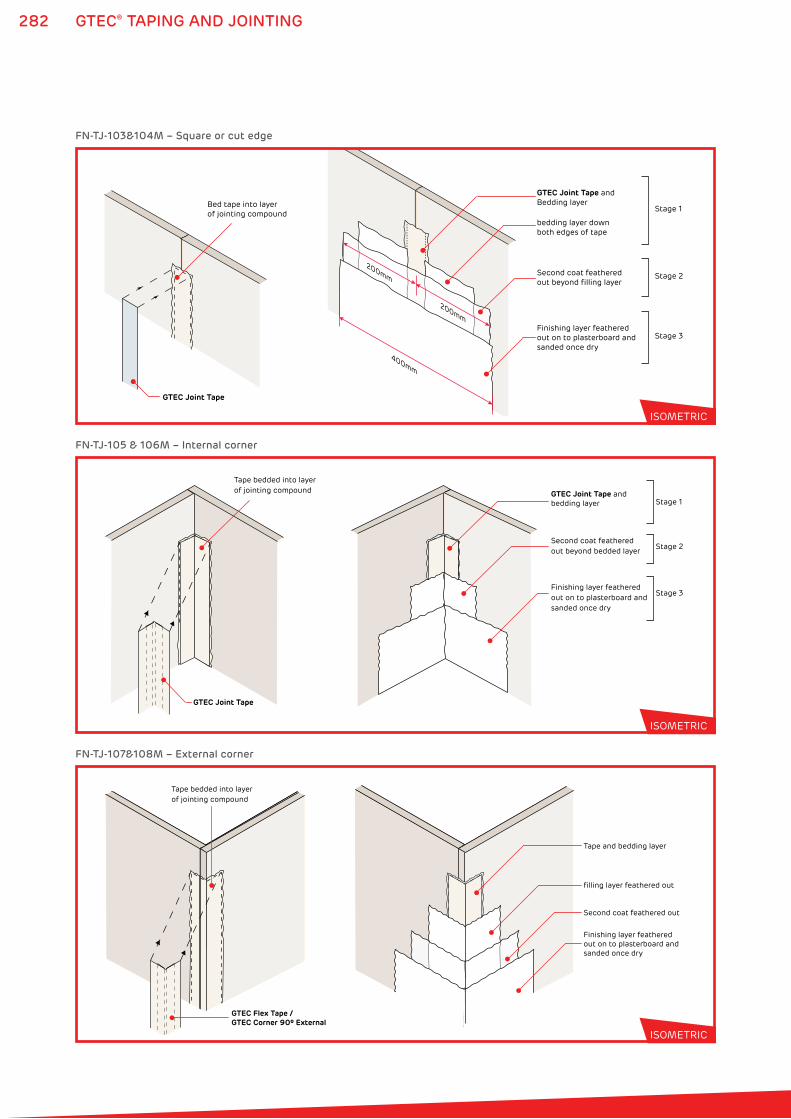
282 GTEC® TAPING AND JOINTING
GTEC Joint Tape
Tape bedded into layerof jointing compound
Second coat featheredout beyond bedded layer
Finishing layer feathered out on to plasterboard and sanded once dry
GTEC Joint Tape and bedding layer Stage 1
Stage 2
Stage 3
FN-TJ-105 & 106M – Internal corner
ISOMETRIC
GTEC Flex Tape / GTEC Corner 90º External
Tape bedded into layerof jointing compound
Second coat feathered out
filling layer feathered out
Finishing layer feathered out on to plasterboard and sanded once dry
Tape and bedding layer
FN-TJ-107&108M – External corner
ISOMETRIC
GTEC Joint Tape
Bed tape into layer of jointing compound
200mm
200mm
400mm
GTEC Joint Tape and Bedding layer
bedding layer down both edges of tape
Second coat featheredout beyond filling layer
Finishing layer feathered out on to plasterboard and sanded once dry
Stage 1
Stage 2
Stage 3
FN-TJ-103&104M – Square or cut edge
ISOMETRIC
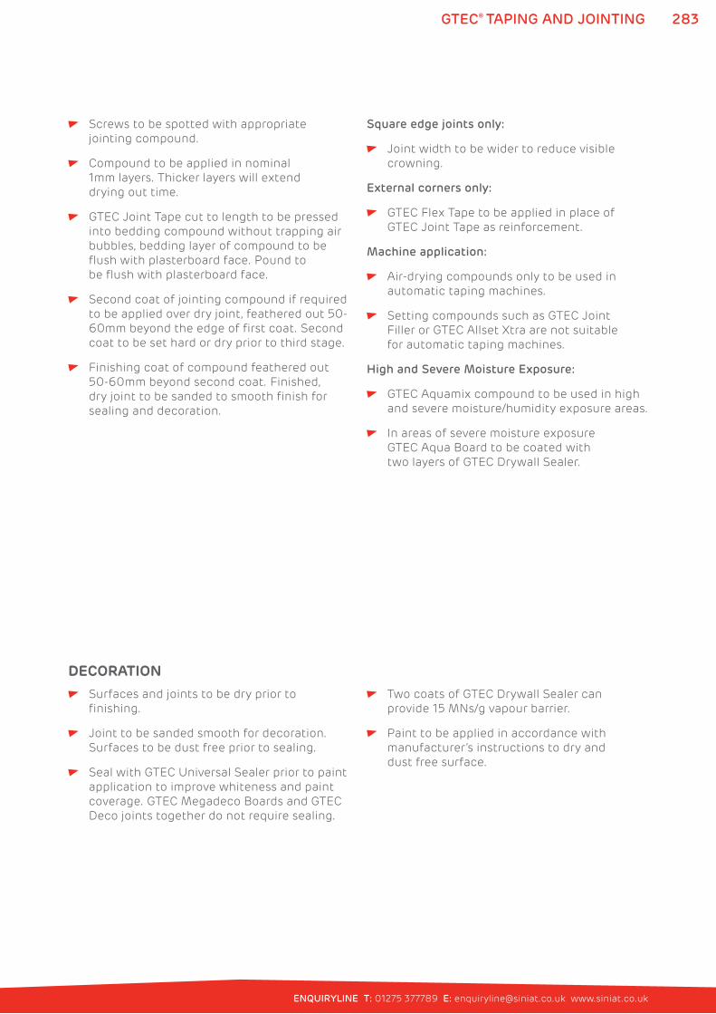
283
ENQUIRYLINE T: 01275 377789 E: [email protected] www.siniat.co.uk
GTEC® TAPING AND JOINTING
Screws to be spotted with appropriate
jointing compound.
Compound to be applied in nominal
1mm layers. Thicker layers will extend
drying out time.
GTEC Joint Tape cut to length to be pressed
into bedding compound without trapping air
bubbles, bedding layer of compound to be
flush with plasterboard face. Pound to
be flush with plasterboard face.
Second coat of jointing compound if required
to be applied over dry joint, feathered out 50-
60mm beyond the edge of first coat. Second
coat to be set hard or dry prior to third stage.
Finishing coat of compound feathered out
50-60mm beyond second coat. Finished,
dry joint to be sanded to smooth finish for
sealing and decoration.
Square edge joints only:
Joint width to be wider to reduce visible
crowning.
External corners only:
GTEC Flex Tape to be applied in place of
GTEC Joint Tape as reinforcement.
Machine application:
Air-drying compounds only to be used in
automatic taping machines.
Setting compounds such as GTEC Joint
Filler or GTEC Allset Xtra are not suitable
for automatic taping machines.
High and Severe Moisture Exposure:
GTEC Aquamix compound to be used in high
and severe moisture/humidity exposure areas.
In areas of severe moisture exposure
GTEC Aqua Board to be coated with
two layers of GTEC Drywall Sealer.
Surfaces and joints to be dry prior to
finishing.
Joint to be sanded smooth for decoration.
Surfaces to be dust free prior to sealing.
Seal with GTEC Universal Sealer prior to paint
application to improve whiteness and paint
coverage. GTEC Megadeco Boards and GTEC
Deco joints together do not require sealing.
Two coats of GTEC Drywall Sealer can
provide 15 MNs/g vapour barrier.
Paint to be applied in accordance with
manufacturer’s instructions to dry and
dust free surface.
DECORATION
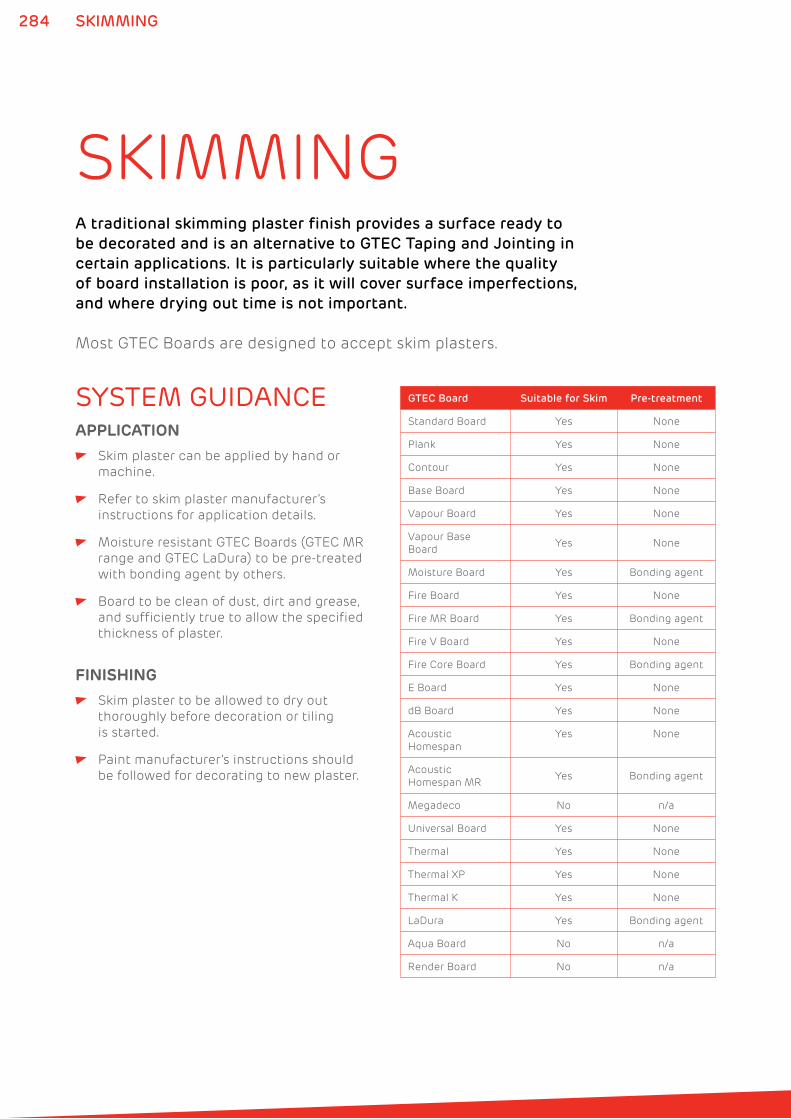
284 SKIMMING
SKIMMINGA traditional skimming plaster finish provides a surface ready to
be decorated and is an alternative to GTEC Taping and Jointing in
certain applications. It is particularly suitable where the quality
of board installation is poor, as it will cover surface imperfections,
and where drying out time is not important.
Most GTEC Boards are designed to accept skim plasters.
SYSTEM GUIDANCE
Skim plaster can be applied by hand or
machine.
Refer to skim plaster manufacturer’s
instructions for application details.
Moisture resistant GTEC Boards (GTEC MR
range and GTEC LaDura) to be pre-treated
with bonding agent by others.
Board to be clean of dust, dirt and grease,
and sufficiently true to allow the specified
thickness of plaster.
APPLICATION
Skim plaster to be allowed to dry out
thoroughly before decoration or tiling
is started.
Paint manufacturer’s instructions should
be followed for decorating to new plaster.
FINISHING
GTEC Board Suitable for Skim Pre-treatment
Standard Board Yes None
Plank Yes None
Contour Yes None
Base Board Yes None
Vapour Board Yes None
Vapour Base
BoardYes None
Moisture Board Yes Bonding agent
Fire Board Yes None
Fire MR Board Yes Bonding agent
Fire V Board Yes None
Fire Core Board Yes Bonding agent
E Board Yes None
dB Board Yes None
Acoustic
Homespan
Yes None
Acoustic
Homespan MRYes Bonding agent
Megadeco No n/a
Universal Board Yes None
Thermal Yes None
Thermal XP Yes None
Thermal K Yes None
LaDura Yes Bonding agent
Aqua Board No n/a
Render Board No n/a
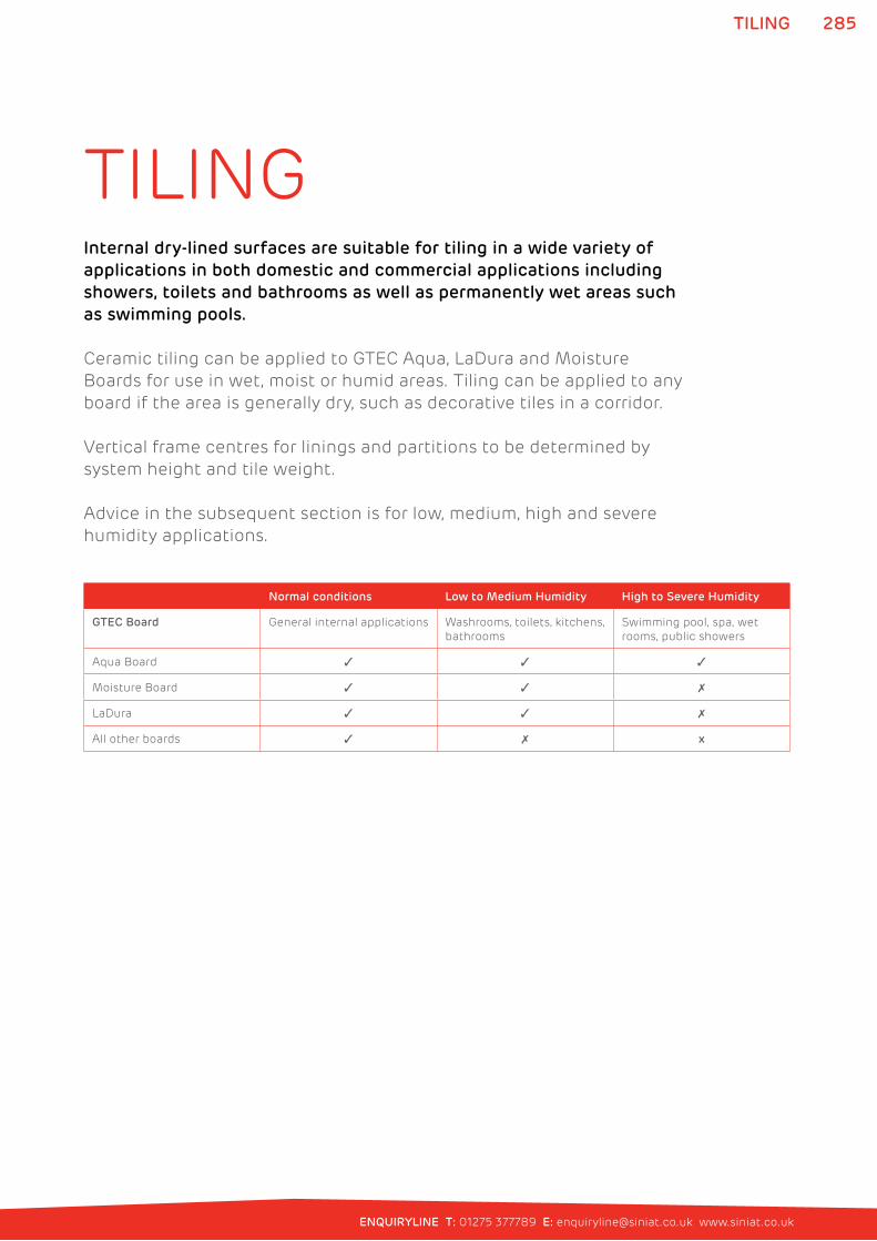
285
ENQUIRYLINE T: 01275 377789 E: [email protected] www.siniat.co.uk
TILING
TILINGInternal dry-lined surfaces are suitable for tiling in a wide variety of
applications in both domestic and commercial applications including
showers, toilets and bathrooms as well as permanently wet areas such
as swimming pools.
Ceramic tiling can be applied to GTEC Aqua, LaDura and Moisture
Boards for use in wet, moist or humid areas. Tiling can be applied to any
board if the area is generally dry, such as decorative tiles in a corridor.
Vertical frame centres for linings and partitions to be determined by
system height and tile weight.
Advice in the subsequent section is for low, medium, high and severe
humidity applications.
Normal conditions Low to Medium Humidity High to Severe Humidity
GTEC Board General internal applications Washrooms, toilets, kitchens,
bathrooms
Swimming pool, spa, wet
rooms, public showers
Aqua Board � � �
Moisture Board � � �
LaDura � � �
All other boards � � x
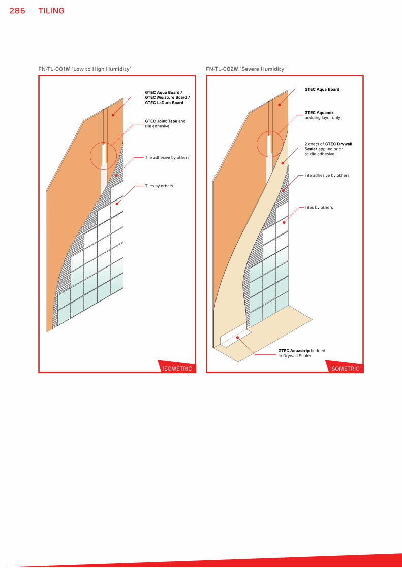
286 TILING
GTEC Aqua Board / GTEC Moisture Board /GTEC LaDura Board
GTEC Joint Tape and tile adhesive
Tile adhesive by others
Tiles by others
GTEC Aqua Board
GTEC Aquamixbedding layer only
Tile adhesive by others
Tiles by others
2 coats of GTEC Drywall Sealer applied prior to tile adhesive
GTEC Aquastrip beddedin Drywall Sealer
FN-TL-001M ‘Low to High Humidity’ FN-TL-002M ‘Severe Humidity’
ISOMETRIC ISOMETRIC
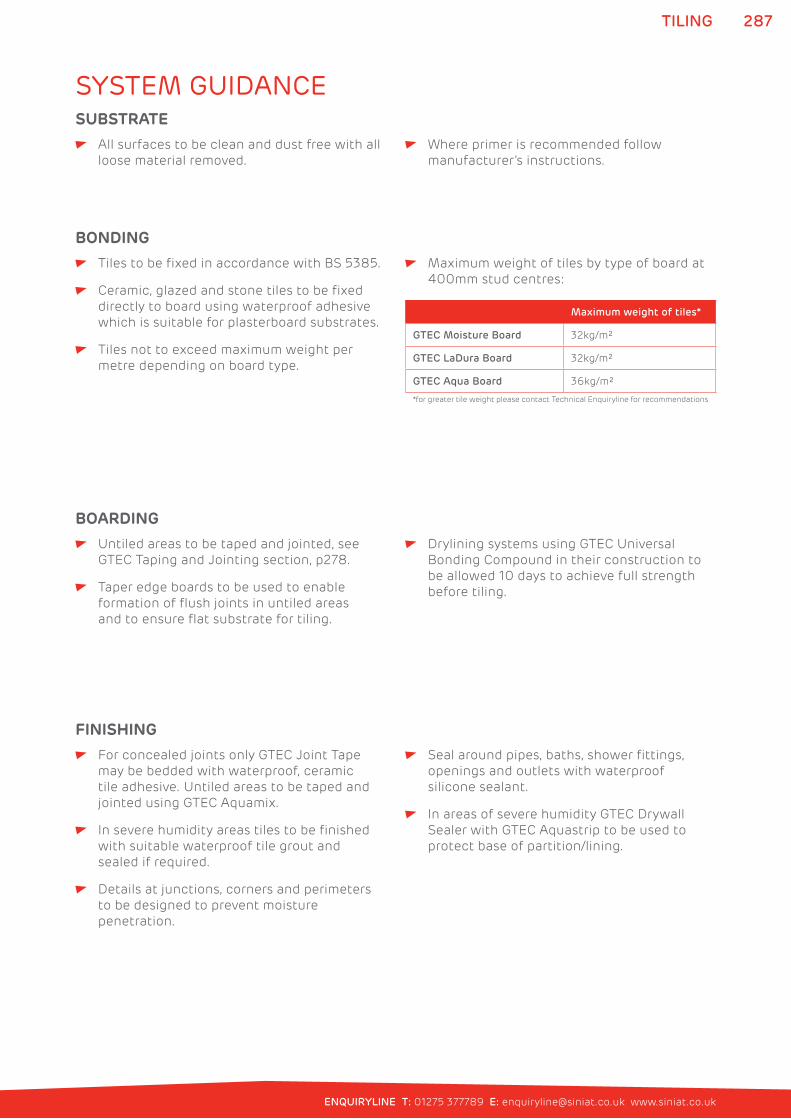
287
ENQUIRYLINE T: 01275 377789 E: [email protected] www.siniat.co.uk
TILING
All surfaces to be clean and dust free with all
loose material removed.
Where primer is recommended follow
manufacturer’s instructions.
SUBSTRATE
Tiles to be fixed in accordance with BS 5385.
Ceramic, glazed and stone tiles to be fixed
directly to board using waterproof adhesive
which is suitable for plasterboard substrates.
Tiles not to exceed maximum weight per
metre depending on board type.
Maximum weight of tiles by type of board at
400mm stud centres:
Maximum weight of tiles*
GTEC Moisture Board 32kg/m²
GTEC LaDura Board 32kg/m²
GTEC Aqua Board 36kg/m²
*for greater tile weight please contact Technical Enquiryline for recommendations
BONDING
Untiled areas to be taped and jointed, see
GTEC Taping and Jointing section, p278.
Taper edge boards to be used to enable
formation of flush joints in untiled areas
and to ensure flat substrate for tiling.
Drylining systems using GTEC Universal
Bonding Compound in their construction to
be allowed 10 days to achieve full strength
before tiling.
BOARDING
For concealed joints only GTEC Joint Tape
may be bedded with waterproof, ceramic
tile adhesive. Untiled areas to be taped and
jointed using GTEC Aquamix.
In severe humidity areas tiles to be finished
with suitable waterproof tile grout and
sealed if required.
Details at junctions, corners and perimeters
to be designed to prevent moisture
penetration.
Seal around pipes, baths, shower fittings,
openings and outlets with waterproof
silicone sealant.
In areas of severe humidity GTEC Drywall
Sealer with GTEC Aquastrip to be used to
protect base of partition/lining.
FINISHING
SYSTEM GUIDANCE
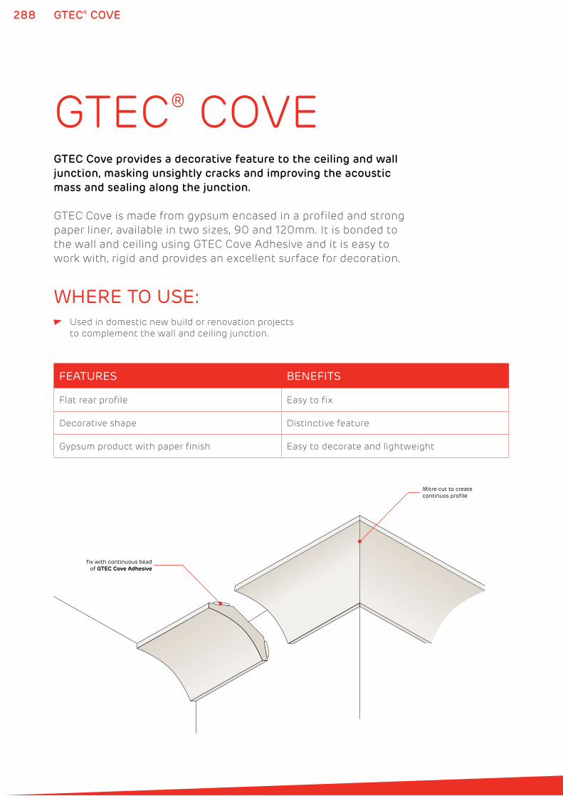
288 GTEC® COVE
GTEC® COVEGTEC Cove provides a decorative feature to the ceiling and wall
junction, masking unsightly cracks and improving the acoustic
mass and sealing along the junction.
GTEC Cove is made from gypsum encased in a profiled and strong
paper liner, available in two sizes, 90 and 120mm. It is bonded to
the wall and ceiling using GTEC Cove Adhesive and it is easy to
work with, rigid and provides an excellent surface for decoration.
WHERE TO USE: Used in domestic new build or renovation projects
to complement the wall and ceiling junction.
FEATURES BENEFITS
Flat rear profile Easy to fix
Decorative shape Distinctive feature
Gypsum product with paper finish Easy to decorate and lightweight
Mitre cut to create continuos profile
fix with continuous beadof GTEC Cove Adhesive
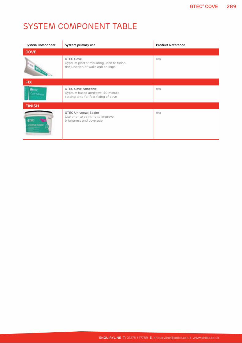
289
ENQUIRYLINE T: 01275 377789 E: [email protected] www.siniat.co.uk
GTEC® COVE
System Component System primary use Product Reference
COVE
GTEC Cove
Gypsum plaster moulding used to finish
the junction of walls and ceilings
n/a
FIX
GTEC Cove Adhesive
Gypsum based adhesive, 40 minute
setting time for fast fixing of cove
n/a
FINISH
GTEC Universal Sealer
Use prior to painting to improve
brightness and coverage
n/a
SYSTEM COMPONENT TABLE
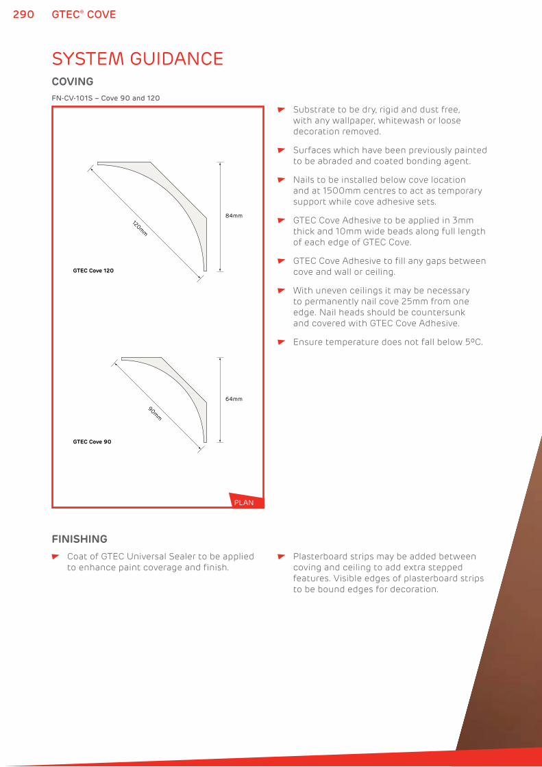
290 GTEC® COVE
120mm
90mm
GTEC Cove 120
GTEC Cove 90
84mm
64mm
FN-CV-101S – Cove 90 and 120
COVING
SYSTEM GUIDANCE
Substrate to be dry, rigid and dust free,
with any wallpaper, whitewash or loose
decoration removed.
Surfaces which have been previously painted
to be abraded and coated bonding agent.
Nails to be installed below cove location
and at 1500mm centres to act as temporary
support while cove adhesive sets.
GTEC Cove Adhesive to be applied in 3mm
thick and 10mm wide beads along full length
of each edge of GTEC Cove.
GTEC Cove Adhesive to fill any gaps between
cove and wall or ceiling.
With uneven ceilings it may be necessary
to permanently nail cove 25mm from one
edge. Nail heads should be countersunk
and covered with GTEC Cove Adhesive.
Ensure temperature does not fall below 5ºC.
Coat of GTEC Universal Sealer to be applied
to enhance paint coverage and finish.
Plasterboard strips may be added between
coving and ceiling to add extra stepped
features. Visible edges of plasterboard strips
to be bound edges for decoration.
FINISHING
PLAN

REFERENCE292
293
ENQUIRYLINE T: 01275 377789 E: [email protected] www.siniat.co.uk
REFERENCEProduct Reference
GTEC Board 294
GTEC Frame 308
GTEC Fix 321
GTEC Finish 324
Profile Guide 332
Screw Selection Guide 334
Sustainability 336
Health and Safety 341
Standards 342
Index 344
293
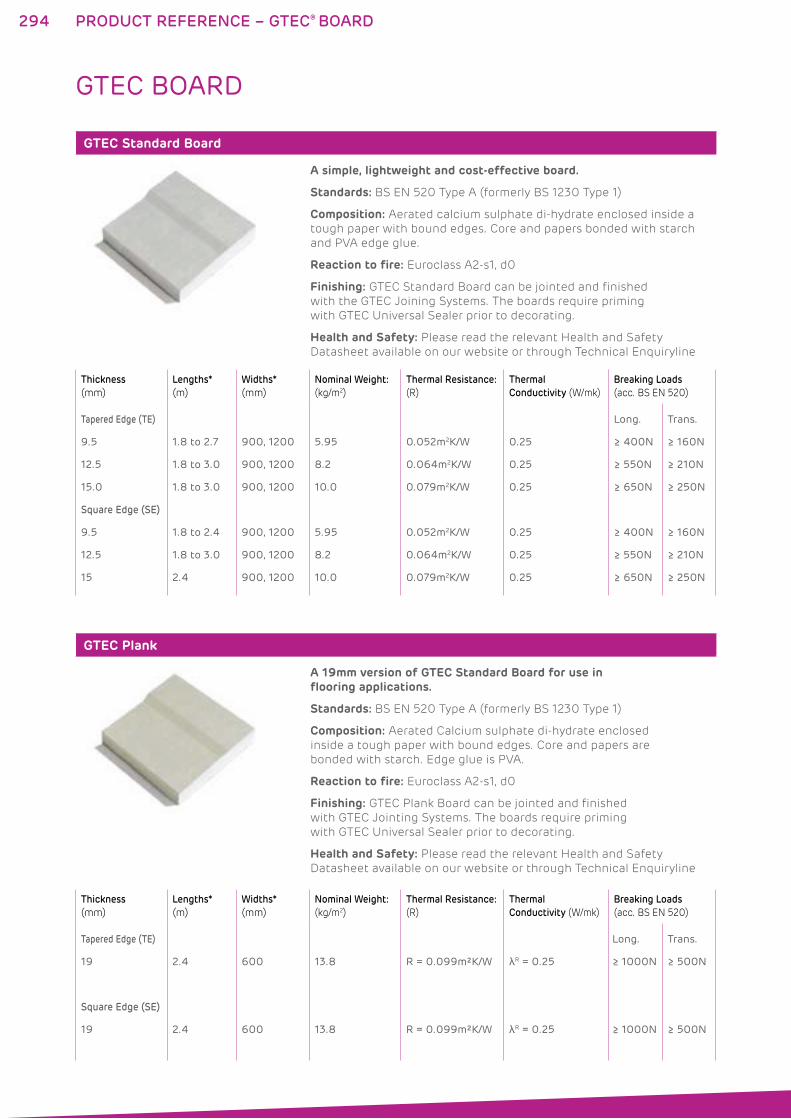
294
GTEC Standard Board
A simple, lightweight and cost-effective board.
Standards: BS EN 520 Type A (formerly BS 1230 Type 1)
Composition: Aerated calcium sulphate di-hydrate enclosed inside a
tough paper with bound edges. Core and papers bonded with starch
and PVA edge glue.
Reaction to fire: Euroclass A2-s1, d0
Finishing: GTEC Standard Board can be jointed and finished
with the GTEC Joining Systems. The boards require priming
with GTEC Universal Sealer prior to decorating.
Health and Safety: Please read the relevant Health and Safety
Datasheet available on our website or through Technical Enquiryline
GTEC Plank
A 19mm version of GTEC Standard Board for use in flooring applications.
Standards: BS EN 520 Type A (formerly BS 1230 Type 1)
Composition: Aerated Calcium sulphate di-hydrate enclosed
inside a tough paper with bound edges. Core and papers are
bonded with starch. Edge glue is PVA.
Reaction to fire: Euroclass A2-s1, d0
Finishing: GTEC Plank Board can be jointed and finished
with GTEC Jointing Systems. The boards require priming
with GTEC Universal Sealer prior to decorating.
Health and Safety: Please read the relevant Health and Safety
Datasheet available on our website or through Technical Enquiryline
PRODUCT REFERENCE – GTEC® BOARD
GTEC BOARD
Thickness
(mm)
Lengths*
(m)
Widths*
(mm)
Nominal Weight:
(kg/m2)
Thermal Resistance:
(R)
Thermal
Conductivity (W/mk)
Breaking Loads
(acc. BS EN 520)
Tapered Edge (TE)
9.5
12.5
15.0
Square Edge (SE)
9.5
12.5
15
1.8 to 2.7
1.8 to 3.0
1.8 to 3.0
1.8 to 2.4
1.8 to 3.0
2.4
900, 1200
900, 1200
900, 1200
900, 1200
900, 1200
900, 1200
5.95
8.2
10.0
5.95
8.2
10.0
0.052m2K/W
0.064m2K/W
0.079m2K/W
0.052m2K/W
0.064m2K/W
0.079m2K/W
0.25
0.25
0.25
0.25
0.25
0.25
Long.
≥ 400N
≥ 550N
≥ 650N
≥ 400N
≥ 550N
≥ 650N
Trans.
≥ 160N
≥ 210N
≥ 250N
≥ 160N
≥ 210N
≥ 250N
Thickness
(mm)
Lengths*
(m)
Widths*
(mm)
Nominal Weight:
(kg/m2)
Thermal Resistance:
(R)
Thermal
Conductivity (W/mk)
Breaking Loads
(acc. BS EN 520)
Tapered Edge (TE)
19
Square Edge (SE)
19
2.4
2.4
600
600
13.8
13.8
R = 0.099m²K/W
R = 0.099m²K/W
λR = 0.25
λR = 0.25
Long.
≥ 1000N
≥ 1000N
Trans.
≥ 500N
≥ 500N
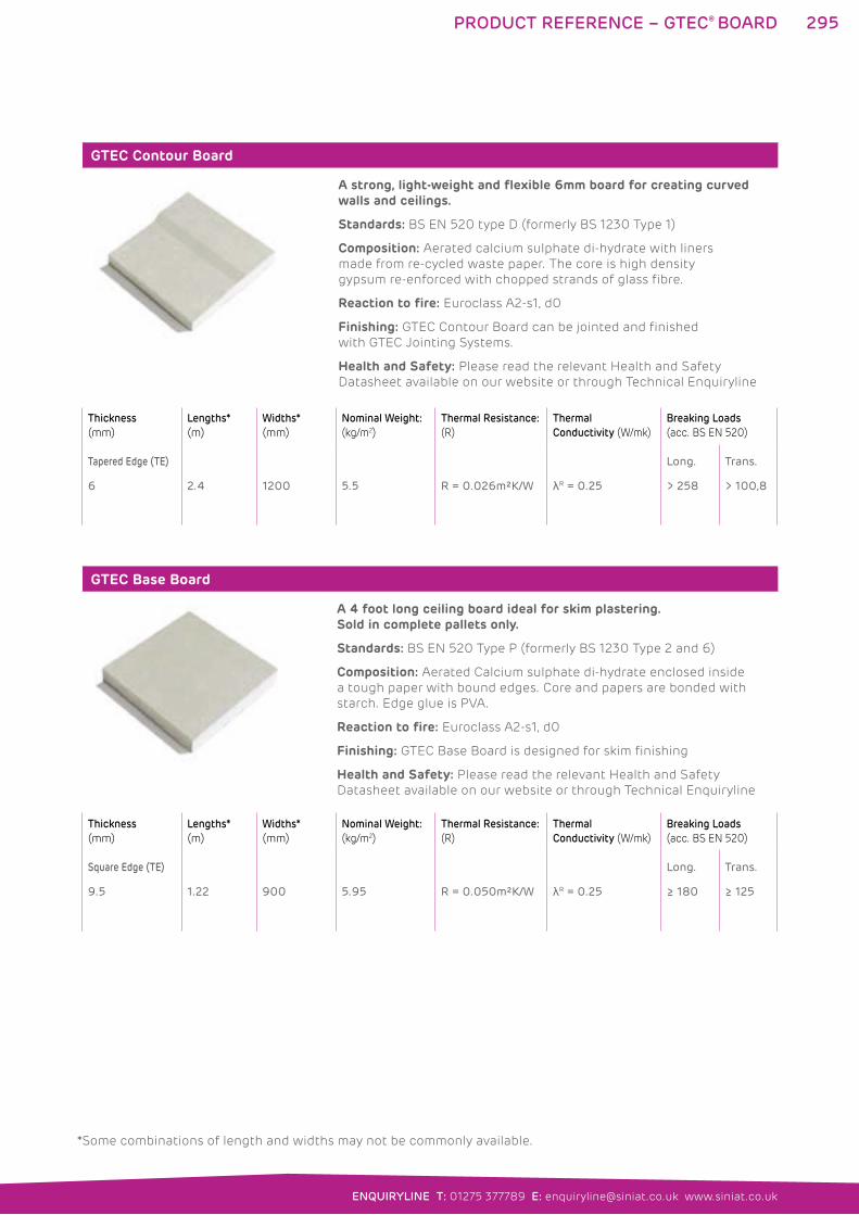
295
ENQUIRYLINE T: 01275 377789 E: [email protected] www.siniat.co.uk
GTEC Contour Board
A strong, light-weight and flexible 6mm board for creating curved walls and ceilings.
Standards: BS EN 520 type D (formerly BS 1230 Type 1)
Composition: Aerated calcium sulphate di-hydrate with liners
made from re-cycled waste paper. The core is high density
gypsum re-enforced with chopped strands of glass fibre.
Reaction to fire: Euroclass A2-s1, d0
Finishing: GTEC Contour Board can be jointed and finished
with GTEC Jointing Systems.
Health and Safety: Please read the relevant Health and Safety
Datasheet available on our website or through Technical Enquiryline
GTEC Base Board
A 4 foot long ceiling board ideal for skim plastering. Sold in complete pallets only.
Standards: BS EN 520 Type P (formerly BS 1230 Type 2 and 6)
Composition: Aerated Calcium sulphate di-hydrate enclosed inside
a tough paper with bound edges. Core and papers are bonded with
starch. Edge glue is PVA.
Reaction to fire: Euroclass A2-s1, d0
Finishing: GTEC Base Board is designed for skim finishing
Health and Safety: Please read the relevant Health and Safety
Datasheet available on our website or through Technical Enquiryline
PRODUCT REFERENCE – GTEC® BOARD
Thickness
(mm)
Lengths*
(m)
Widths*
(mm)
Nominal Weight:
(kg/m2)
Thermal Resistance:
(R)
Thermal
Conductivity (W/mk)
Breaking Loads
(acc. BS EN 520)
Square Edge (TE)
9.5 1.22 900 5.95 R = 0.050m²K/W λR = 0.25
Long.
≥ 180
Trans.
≥ 125
Thickness
(mm)
Lengths*
(m)
Widths*
(mm)
Nominal Weight:
(kg/m2)
Thermal Resistance:
(R)
Thermal
Conductivity (W/mk)
Breaking Loads
(acc. BS EN 520)
Tapered Edge (TE)
6 2.4 1200 5.5 R = 0.026m²K/W λR = 0.25
Long.
> 258
Trans.
> 100,8
*Some combinations of length and widths may not be commonly available.
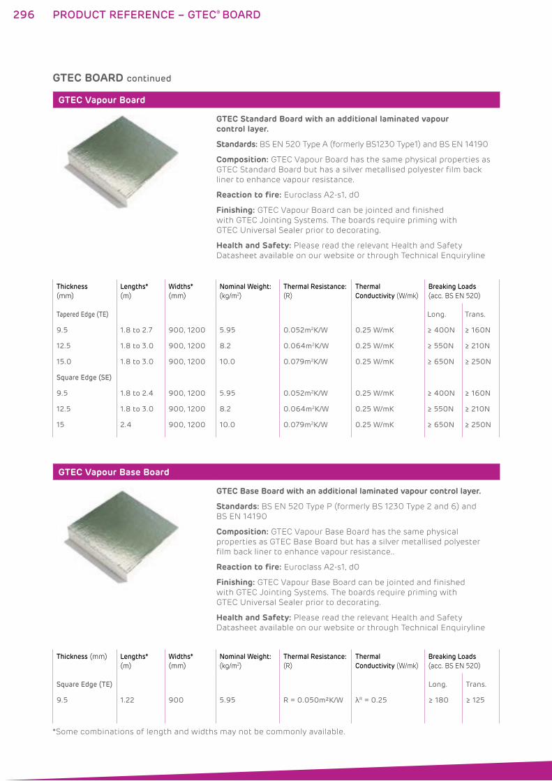
296
GTEC Vapour Board
GTEC Standard Board with an additional laminated vapour control layer.
Standards: BS EN 520 Type A (formerly BS1230 Type1) and BS EN 14190
Composition: GTEC Vapour Board has the same physical properties as
GTEC Standard Board but has a silver metallised polyester film back
liner to enhance vapour resistance.
Reaction to fire: Euroclass A2-s1, d0
Finishing: GTEC Vapour Board can be jointed and finished
with GTEC Jointing Systems. The boards require priming with
GTEC Universal Sealer prior to decorating.
Health and Safety: Please read the relevant Health and Safety
Datasheet available on our website or through Technical Enquiryline
GTEC Vapour Base Board
GTEC Base Board with an additional laminated vapour control layer.
Standards: BS EN 520 Type P (formerly BS 1230 Type 2 and 6) and
BS EN 14190
Composition: GTEC Vapour Base Board has the same physical
properties as GTEC Base Board but has a silver metallised polyester
film back liner to enhance vapour resistance..
Reaction to fire: Euroclass A2-s1, d0
Finishing: GTEC Vapour Base Board can be jointed and finished
with GTEC Jointing Systems. The boards require priming with
GTEC Universal Sealer prior to decorating.
Health and Safety: Please read the relevant Health and Safety
Datasheet available on our website or through Technical Enquiryline
Thickness
(mm)
Lengths*
(m)
Widths*
(mm)
Nominal Weight:
(kg/m2)
Thermal Resistance:
(R)
Thermal
Conductivity (W/mk)
Breaking Loads
(acc. BS EN 520)
Tapered Edge (TE)
9.5
12.5
15.0
Square Edge (SE)
9.5
12.5
15
1.8 to 2.7
1.8 to 3.0
1.8 to 3.0
1.8 to 2.4
1.8 to 3.0
2.4
900, 1200
900, 1200
900, 1200
900, 1200
900, 1200
900, 1200
5.95
8.2
10.0
5.95
8.2
10.0
0.052m2K/W
0.064m2K/W
0.079m2K/W
0.052m2K/W
0.064m2K/W
0.079m2K/W
0.25 W/mK
0.25 W/mK
0.25 W/mK
0.25 W/mK
0.25 W/mK
0.25 W/mK
Long.
≥ 400N
≥ 550N
≥ 650N
≥ 400N
≥ 550N
≥ 650N
Trans.
≥ 160N
≥ 210N
≥ 250N
≥ 160N
≥ 210N
≥ 250N
Thickness (mm) Lengths*
(m)
Widths*
(mm)
Nominal Weight:
(kg/m2)
Thermal Resistance:
(R)
Thermal
Conductivity (W/mk)
Breaking Loads
(acc. BS EN 520)
Square Edge (TE)
9.5 1.22 900 5.95 R = 0.050m²K/W λR = 0.25
Long.
≥ 180
Trans.
≥ 125
GTEC BOARD continued
PRODUCT REFERENCE – GTEC® BOARD
*Some combinations of length and widths may not be commonly available.
297
ENQUIRYLINE T: 01275 377789 E: [email protected] www.siniat.co.uk
GTEC Moisture Board
A board with water resistant additives designed for use in humid areas.
Standards: BS EN 520 Type H1 (formerly BS 1230 Type 3 and 4)
Composition: Aerated Calcium sulphate di-hydrate with fillers
enclosed inside a green paper with bound edges. Core and
papers are bonded with starch. Edge glue is PVA.
Reaction to fire: Euroclass A2-s1, d0
Finishing: GTEC Moisture Board can be jointed and finished
with GTEC jointing systems. The boards require priming with
GTEC Universal Sealer prior to decorating and treating with
PVA bonding agent before plastering.
Health and Safety: Please read the relevant Health and Safety
Datasheet available on our website or through Technical Enquiryline
GTEC Fire Board
Provides superior fire resistance.
Standards: BS EN 520 Types D and F (formerly BS1230 Type 5)
Composition: Aerated Calcium sulphate di-hydrate with fire-resisting
fillers and fibres enclosed inside a tough pink paper with bound
edges. Core and papers are bonded with starch. Edge glue is PVA.
Reaction to fire: Euroclass A2-s1, d0
Finishing: GTEC Fire Board can be jointed and finished with
GTEC Jointing systems. The boards require priming with
GTEC Universal Sealer prior to decorating.
Health and Safety: Please read the relevant Health and Safety
Datasheet available on our website or through Technical Enquiryline
Thickness
(mm)
Lengths*
(m)
Widths*
(mm)
Nominal Weight:
(kg/m2)
Thermal Resistance:
(R)
Thermal
Conductivity (W/mk)
Breaking Loads
(acc. BS EN 520)
Tapered Edge (TE)
12.5 2.4 to 3.0
2.4
1200
1200
9
11.85
R= 0.062m²K/W
R= 0.076m²K/W
λR = 0.24
λR = 0.24
Long.
≥ 550N
≥ 650N
Trans.
≥ 210N
≥ 250N
Thickness
(mm)
Lengths*
(m)
Widths*
(mm)
Nominal Weight:
(kg/m2)
Thermal Resistance:
(R)
Thermal
Conductivity (W/mk)
Breaking Loads
(acc. BS EN 520)
Tapered Edge (TE)
12.5
15
Square Edge (SE)
12.5
1.8 to 3.0
1.8 to 3.0
1.8 to 2.4
900, 1200
900, 1200
900, 1200
10.2
12.3
10.2
R= 0.052m²K/W
R= 0.062m²K/W
R= 0.052m²K/W
λR = 0.24
λR = 0.24
λR = 0.24
Long.
≥ 725N
≥ 870N
≥ 725N
Trans.
≥ 300N
≥ 360N
≥ 300N
PRODUCT REFERENCE – GTEC® BOARD
298
GTEC Fire MR Board
Provides both fire and moisture resistance.
Standards: BS EN 520 Types D, F and H1 (formerly BS 1230 Types 3, 4
and 5)
Composition: Aerated Calcium sulphate di-hydrate with fire-resisting
fillers and fibres enclosed inside a tough pink paper with bound
edges. Core and papers are bonded with starch. Edge glue is PVA.
Reaction to fire: Euroclass A2-s1, d0
Finishing: GTEC Fire MR Board can be jointed and finished with GTEC
Jointing systems. The boards require priming with GTEC Universal
Sealer prior to decorating. Requires PVA treatment prior to skimming.
Health and Safety: Please read the relevant Health and Safety
Datasheet available on our website or through Technical Enquiryline
GTEC Fire V Board
GTEC Fire Board with an additional laminated vapour control.
Standards: BS EN 520 Types D and F (formerly BS1230 Type 5)
and BS EN 14190
Composition: GTEC Fire Vapour Board has same physical properties
as GTEC Fire Board but has a silver metallised polyester film back liner
to enhance vapour resistance
Reaction to fire: Euroclass A2-s1, d0
Finishing: GTEC Fire V Board can be jointed and finished
with GTEC Jointing systems. The boards require priming
with GTEC Universal Sealer prior to decorating.
Health and Safety: Please read the relevant Health and Safety
Datasheet available on our website or through Technical Enquiryline
Thickness
(mm)
Lengths*
(m)
Widths*
(mm)
Nominal Weight:
(kg/m2)
Thermal Resistance:
(R)
Thermal
Conductivity (W/mk)
Breaking Loads
(acc. BS EN 520)
Tapered Edge (TE)
12.5
15
2.4
2.4 to 3.0
1200
1200
10.3
12.5
R= 0.05m²K/W
R= 0.06m²K/W
λR = .25
Long.
≥ 550N
≥ 650N
Trans.
≥ 210N
≥ 250N
Thickness
(mm)
Lengths*
(m)
Widths*
(mm)
Nominal Weight:
(kg/m2)
Thermal Resistance:
(R)
Thermal
Conductivity (W/mk)
Breaking Loads
(acc. BS EN 520)
Tapered Edge (TE)
12.5
15
1.8 to 3.0
1.8 to 3.0
900, 1200
900, 1200
10.2
12.3
R= 0.052m²K/W
R= 0.062m²K/W
λR = 0.24
λR = 0.24
Long.
≥ 725N
≥ 870N
Trans.
≥ 300N
≥ 360N
GTEC BOARD continued
PRODUCT REFERENCE – GTEC® BOARD
*Some combinations of length and widths may not be commonly available.
299
ENQUIRYLINE T: 01275 377789 E: [email protected] www.siniat.co.uk
GTEC Fire Core Board
High strength fire resistant board for use in GTEC Shaftwall systems, steelwork fire encasement.
Standards: BS EN 520 Types D, H1I and R (formerly BS 1230 Types 3, 4
and 5)
Composition: Aerated Calcium sulphate di-hydrate with fire-resisting
fillers and fibres enclosed inside a moisture resistant paper with
bound edges. Core and papers are bonded with starch.
Edge glue is PVA.
Reaction to fire: Euroclass A2-s1, d0
Finishing: GTEC Fire Core Board can be jointed and finished
with GTEC Jointing systems. The boards require priming with
GTEC Universal Sealer prior to decorating.
Health and Safety: Please read the relevant Health and Safety
Datasheet available on our website or through Technical Enquiryline
GTEC E Board
Engineered for use within dwellings to comply with the latest Building Regulations Approved Document E Regulations.
Standards: BS 520 Type D (formerly BS 1230 Type 1)
Composition: Aerated Calcium sulphate di-hydrate inside tough liner
papers with bound edges. Core and papers are bonded with starch.
Edge glue is PVA.
Reaction to fire: Euroclass A2-s1, d0
Finishing: GTEC E Board can be jointed and finished with any of the
GTEC Jointing systems. It can be plastered on either side using single
coat proprietary gypsum finishing plasters not less then 2mm thick.
Health and Safety: Please read the relevant Health and Safety
Datasheet available on our website or through Technical Enquiryline
Thickness
(mm)
Lengths*
(m)
Widths*
(mm)
Nominal Weight:
(kg/m2)
Thermal Resistance:
(R)
Thermal
Conductivity (W/mk)
Breaking Loads
(acc. BS EN 520)
Tapered Edge (TE)
25 3 600 21.6 R= 0.089m²K/W λR = 0.28
Long.
≥ 1500N
Trans.
≥ 700N
Thickness
(mm)
Lengths*
(m)
Widths*
(mm)
Nominal Weight:
(kg/m2)
Thermal Resistance:
(R)
Thermal
Conductivity (W/mk)
Breaking Loads
(acc. BS EN 520)
Tapered Edge (TE)
12.5 2.4 1200 10.2 R = 0.052m²K/W λR = 0.24
Long.
≥ 550N
Trans.
≥ 250N
PRODUCT REFERENCE – GTEC® BOARD
300
GTEC dB Board
For superior acoustic performance.
Standards: BS EN 520 Types D and I (formerly BS 1230 Type 1)
Composition: Aerated Calcium sulphate di-hydrate with fillers
and fibres enclosed inside tough liner papers with bound edges.
Core and papers are bonded with starch. Edge glue is PVA.
Reaction to fire: Euroclass A2-s1, d0
Finishing: GTEC dB Board can be jointed and finished with any of the
GTEC Jointing systems. It can be plastered on either side using single
coat proprietary gypsum finishing plasters not less then 2mm thick.
The blue liner paper requires more paint obscuration than normal
ivory liner. Allow 10 litres / 100m2.
Health and Safety: Please read the relevant Health and Safety
Datasheet available on our website or through Technical Enquiryline
GTEC Acoustic Homespan Board
For use with the GTEC Acoustic Homespan Partition System.
Standards: BS EN 520 Type D (formerly BS 1230 Type 1)
Composition: Aerated Calcium sulphate di-hydrate with fillers
and fibres enclosed inside tough liner papers with bound edges.
Core and papers are bonded with starch. Edge glue is PVA.
Reaction to fire: Euroclass A2-s1, d0
Finishing: GTEC Acoustic Homespan Board can be jointed and
finished with GTEC Jointing systems. The boards require priming
with GTEC Universal Sealer prior to decorating.
Health and Safety: Please read the relevant Health and Safety
Datasheet available on our website or through Technical Enquiryline
Thickness
(mm)
Lengths*
(m)
Widths*
(mm)
Nominal Weight:
(kg/m2)
Thermal Resistance:
(R)
Thermal
Conductivity (W/mk)
Breaking Loads
(acc. BS EN 520)
Tapered Edge (TE)
12.5
15
2.4
2.4 to 3.0
1200
1200
11
13
R= 0.046m²K/W
R= 0.056m²K/W
λR = 0.27
Long.
≥ 550N
≥ 700N
Trans.
≥ 210N
≥ 300N
Thickness
(mm)
Lengths*
(m)
Widths*
(mm)
Nominal Weight:
(kg/m2)
Thermal Resistance:
(R)
Thermal
Conductivity (W/mk)
Breaking Loads
(acc. BS EN 520)
Tapered Edge (TE)
15 2.4 to 2.7 900 12.7 R= 0.060m²K/W λR = 0.27
Long.
≥ 250N
Trans.
≥ 350N
GTEC BOARD continued
PRODUCT REFERENCE – GTEC® BOARD
*Some combinations of length and widths may not be commonly available.
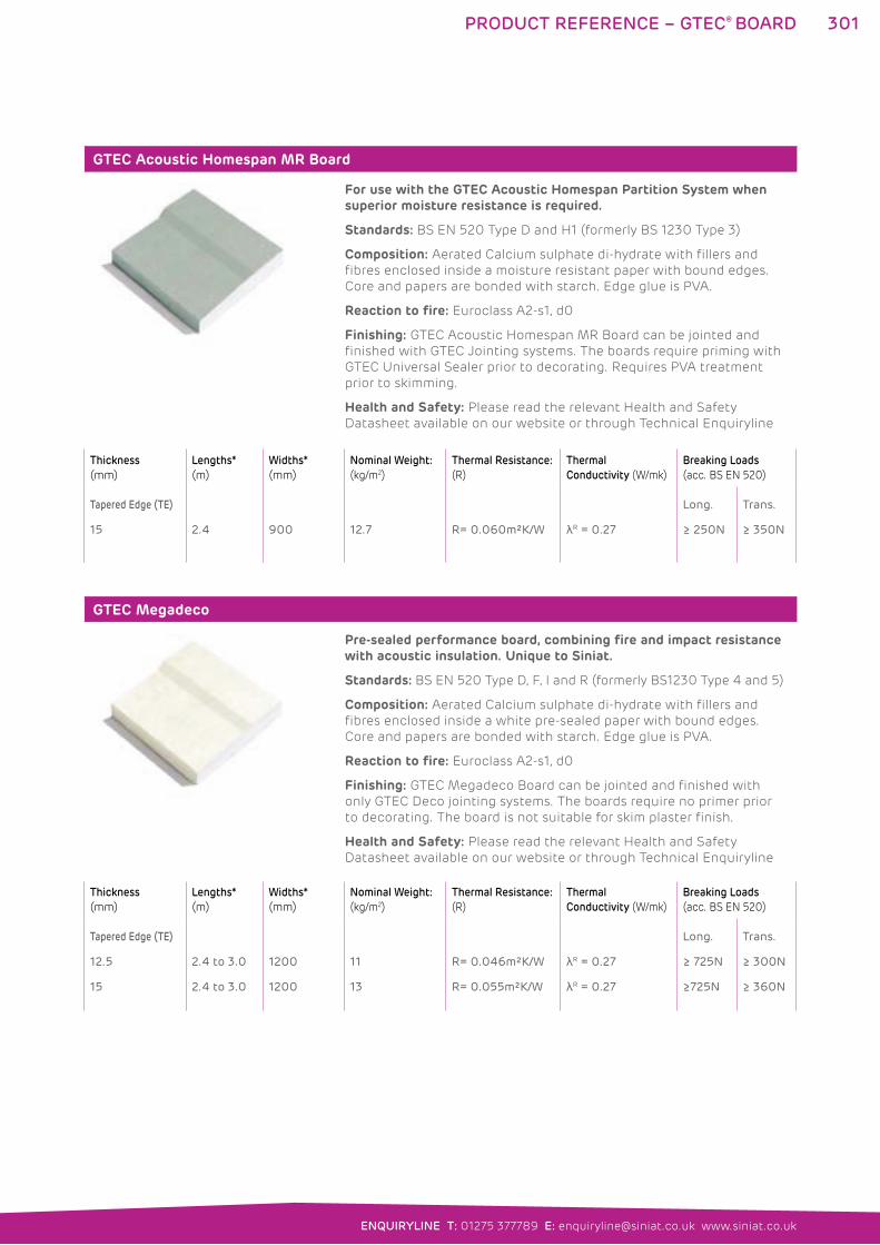
301
ENQUIRYLINE T: 01275 377789 E: [email protected] www.siniat.co.uk
GTEC Acoustic Homespan MR Board
For use with the GTEC Acoustic Homespan Partition System when superior moisture resistance is required.
Standards: BS EN 520 Type D and H1 (formerly BS 1230 Type 3)
Composition: Aerated Calcium sulphate di-hydrate with fillers and
fibres enclosed inside a moisture resistant paper with bound edges.
Core and papers are bonded with starch. Edge glue is PVA.
Reaction to fire: Euroclass A2-s1, d0
Finishing: GTEC Acoustic Homespan MR Board can be jointed and
finished with GTEC Jointing systems. The boards require priming with
GTEC Universal Sealer prior to decorating. Requires PVA treatment
prior to skimming.
Health and Safety: Please read the relevant Health and Safety
Datasheet available on our website or through Technical Enquiryline
GTEC Megadeco
Pre-sealed performance board, combining fire and impact resistance with acoustic insulation. Unique to Siniat.
Standards: BS EN 520 Type D, F, I and R (formerly BS1230 Type 4 and 5)
Composition: Aerated Calcium sulphate di-hydrate with fillers and
fibres enclosed inside a white pre-sealed paper with bound edges.
Core and papers are bonded with starch. Edge glue is PVA.
Reaction to fire: Euroclass A2-s1, d0
Finishing: GTEC Megadeco Board can be jointed and finished with
only GTEC Deco jointing systems. The boards require no primer prior
to decorating. The board is not suitable for skim plaster finish.
Health and Safety: Please read the relevant Health and Safety
Datasheet available on our website or through Technical Enquiryline
Thickness
(mm)
Lengths*
(m)
Widths*
(mm)
Nominal Weight:
(kg/m2)
Thermal Resistance:
(R)
Thermal
Conductivity (W/mk)
Breaking Loads
(acc. BS EN 520)
Tapered Edge (TE)
15 2.4 900 12.7 R= 0.060m²K/W λR = 0.27
Long.
≥ 250N
Trans.
≥ 350N
Thickness
(mm)
Lengths*
(m)
Widths*
(mm)
Nominal Weight:
(kg/m2)
Thermal Resistance:
(R)
Thermal
Conductivity (W/mk)
Breaking Loads
(acc. BS EN 520)
Tapered Edge (TE)
12.5
15
2.4 to 3.0
2.4 to 3.0
1200
1200
11
13
R= 0.046m²K/W
R= 0.055m²K/W
λR = 0.27
λR = 0.27
Long.
≥ 725N
≥725N
Trans.
≥ 300N
≥ 360N
PRODUCT REFERENCE – GTEC® BOARD
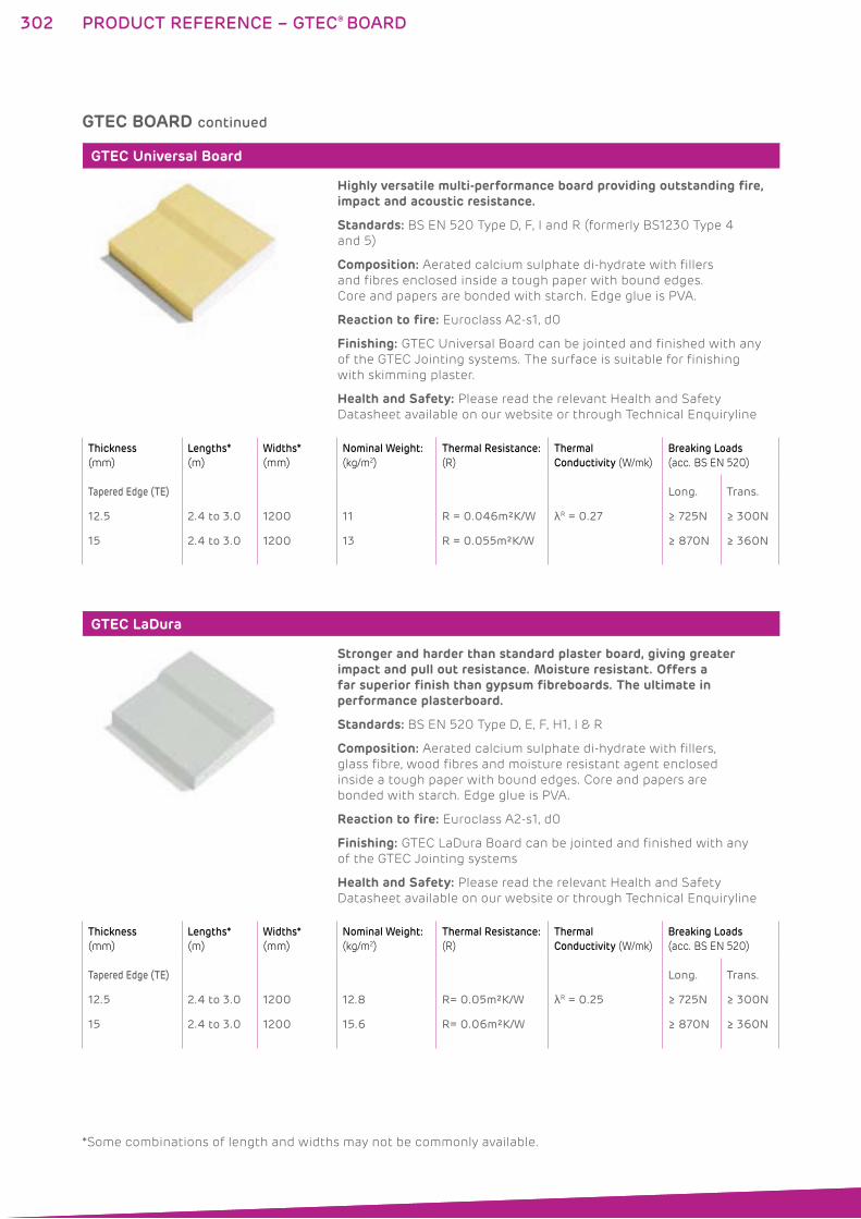
302
GTEC Universal Board
Highly versatile multi-performance board providing outstanding fire, impact and acoustic resistance.
Standards: BS EN 520 Type D, F, I and R (formerly BS1230 Type 4
and 5)
Composition: Aerated calcium sulphate di-hydrate with fillers
and fibres enclosed inside a tough paper with bound edges.
Core and papers are bonded with starch. Edge glue is PVA.
Reaction to fire: Euroclass A2-s1, d0
Finishing: GTEC Universal Board can be jointed and finished with any
of the GTEC Jointing systems. The surface is suitable for finishing
with skimming plaster.
Health and Safety: Please read the relevant Health and Safety
Datasheet available on our website or through Technical Enquiryline
GTEC LaDura
Stronger and harder than standard plaster board, giving greater impact and pull out resistance. Moisture resistant. Offers a far superior finish than gypsum fibreboards. The ultimate in performance plasterboard.
Standards: BS EN 520 Type D, E, F, H1, I & R
Composition: Aerated calcium sulphate di-hydrate with fillers,
glass fibre, wood fibres and moisture resistant agent enclosed
inside a tough paper with bound edges. Core and papers are
bonded with starch. Edge glue is PVA.
Reaction to fire: Euroclass A2-s1, d0
Finishing: GTEC LaDura Board can be jointed and finished with any
of the GTEC Jointing systems
Health and Safety: Please read the relevant Health and Safety
Datasheet available on our website or through Technical Enquiryline
Thickness
(mm)
Lengths*
(m)
Widths*
(mm)
Nominal Weight:
(kg/m2)
Thermal Resistance:
(R)
Thermal
Conductivity (W/mk)
Breaking Loads
(acc. BS EN 520)
Tapered Edge (TE)
12.5
15
2.4 to 3.0
2.4 to 3.0
1200
1200
11
13
R = 0.046m²K/W
R = 0.055m²K/W
λR = 0.27
Long.
≥ 725N
≥ 870N
Trans.
≥ 300N
≥ 360N
Thickness
(mm)
Lengths*
(m)
Widths*
(mm)
Nominal Weight:
(kg/m2)
Thermal Resistance:
(R)
Thermal
Conductivity (W/mk)
Breaking Loads
(acc. BS EN 520)
Tapered Edge (TE)
12.5
15
2.4 to 3.0
2.4 to 3.0
1200
1200
12.8
15.6
R= 0.05m²K/W
R= 0.06m²K/W
λR = 0.25
Long.
≥ 725N
≥ 870N
Trans.
≥ 300N
≥ 360N
GTEC BOARD continued
PRODUCT REFERENCE – GTEC® BOARD
*Some combinations of length and widths may not be commonly available.
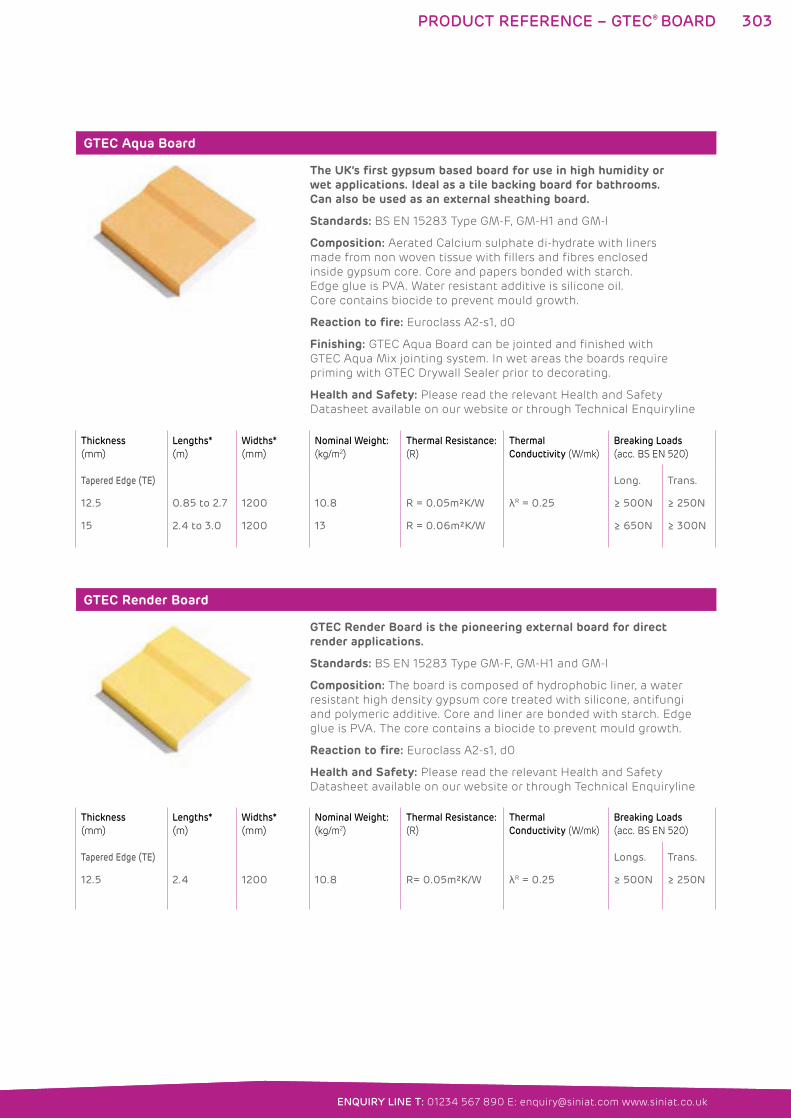
303
ENQUIRYLINE T: 01275 377789 E: [email protected] www.siniat.co.uk
GTEC Aqua Board
The UK’s first gypsum based board for use in high humidity or wet applications. Ideal as a tile backing board for bathrooms. Can also be used as an external sheathing board.
Standards: BS EN 15283 Type GM-F, GM-H1 and GM-I
Composition: Aerated Calcium sulphate di-hydrate with liners
made from non woven tissue with fillers and fibres enclosed
inside gypsum core. Core and papers bonded with starch.
Edge glue is PVA. Water resistant additive is silicone oil.
Core contains biocide to prevent mould growth.
Reaction to fire: Euroclass A2-s1, d0
Finishing: GTEC Aqua Board can be jointed and finished with
GTEC Aqua Mix jointing system. In wet areas the boards require
priming with GTEC Drywall Sealer prior to decorating.
Health and Safety: Please read the relevant Health and Safety
Datasheet available on our website or through Technical Enquiryline
GTEC Render Board
GTEC Render Board is the pioneering external board for direct render applications.
Standards: BS EN 15283 Type GM-F, GM-H1 and GM-I
Composition: The board is composed of hydrophobic liner, a water
resistant high density gypsum core treated with silicone, antifungi
and polymeric additive. Core and liner are bonded with starch. Edge
glue is PVA. The core contains a biocide to prevent mould growth.
Reaction to fire: Euroclass A2-s1, d0
Health and Safety: Please read the relevant Health and Safety
Datasheet available on our website or through Technical Enquiryline
Thickness
(mm)
Lengths*
(m)
Widths*
(mm)
Nominal Weight:
(kg/m2)
Thermal Resistance:
(R)
Thermal
Conductivity (W/mk)
Breaking Loads
(acc. BS EN 520)
Tapered Edge (TE)
12.5
15
0.85 to 2.7
2.4 to 3.0
1200
1200
10.8
13
R = 0.05m²K/W
R = 0.06m²K/W
λR = 0.25
Long.
≥ 500N
≥ 650N
Trans.
≥ 250N
≥ 300N
Thickness
(mm)
Lengths*
(m)
Widths*
(mm)
Nominal Weight:
(kg/m2)
Thermal Resistance:
(R)
Thermal
Conductivity (W/mk)
Breaking Loads
(acc. BS EN 520)
Tapered Edge (TE)
12.5 2.4 1200 10.8 R= 0.05m²K/W λR = 0.25
Longs.
≥ 500N
Trans.
≥ 250N
ENQUIRY LINE T: 01234 567 890 E: [email protected] www.siniat.co.uk
PRODUCT REFERENCE – GTEC® BOARD
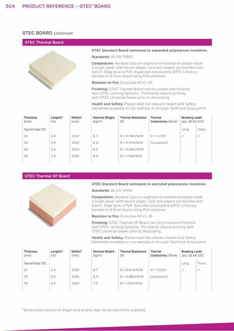
304
GTEC Thermal Board
GTEC Standard Board laminated to expanded polystyrene insulation.
Standards: BS EN 13950
Composition: Aerated Calcium sulphate di-hydrate enclosed inside
a tough paper with bound edges. Core and papers are bonded with
starch. Edge glue is PVA. Expanded polystyrene (EPS) is factory
bonded to 9.5mm board using PVA adhesive.
Reaction to fire: Euroclass A2-s1, d0
Finishing: GTEC Thermal Board can be jointed and finished
with GTEC Jointing Systems. The boards require priming
with GTEC Universal Sealer prior to decorating.
Health and Safety: Please read the relevant Health and Safety
Datasheet available on our website or through Technical Enquiryline
GTEC Thermal XP Board
GTEC Standard Board laminated to extruded polystyrene insulation.
Standards: BS EN 13950
Composition: Aerated Calcium sulphate di-hydrate enclosed inside
a tough paper with bound edges. Core and papers are bonded with
starch. Edge glue is PVA. Extruded polystyrene (XPS) is factory
bonded to 9.5mm board using PVA adhesive.
Reaction to fire: Euroclass A2-s1, d0
Finishing: GTEC Thermal XP Board can be jointed and finished
with GTEC Jointing Systems. The boards require priming with
GTEC Universal Sealer prior to decorating.
Health and Safety: Please read the relevant Health and Safety
Datasheet available on our website or through Technical Enquiryline
Thickness
(mm)
Lengths*
(m)
Widths*
(mm)
Nominal Weight:
(kg/m2)
Thermal Resistance:
(R)
Thermal
Conductivity (W/mk)
Breaking Loads
(acc. BS EN 520)
Tapered Edge (TE)
22
30
40
50
2.4
2.4
2.4
2.4
1200
1200
1200
1200
6.3
6.4
6.5
6.6
R = 0.36m²K/W
R = 0.57m²K/W
R = 0.84m²K/W
R = 1.10m²K/W
λR = 0.037
(insulation)
Long.
–
Trans.
–
Thickness
(mm)
Lengths*
(m)
Widths*
(mm)
Nominal Weight:
(kg/m2)
Thermal Resistance:
(R)
Thermal
Conductivity (W/mk)
Breaking Loads
(acc. BS EN 520)
Tapered Edge (TE)
27
35
55
2.4
2.4
2.4
1200
1200
1200
6.7
6.9
7.4
R = 0.61m²K/W
R = 0.88m²K/W
R = 1.55m²K/W
λR = 0.033
(insulation)
Long.
–
Trans.
–
GTEC BOARD continued
PRODUCT REFERENCE – GTEC® BOARD
*Some combinations of length and widths may not be commonly available.
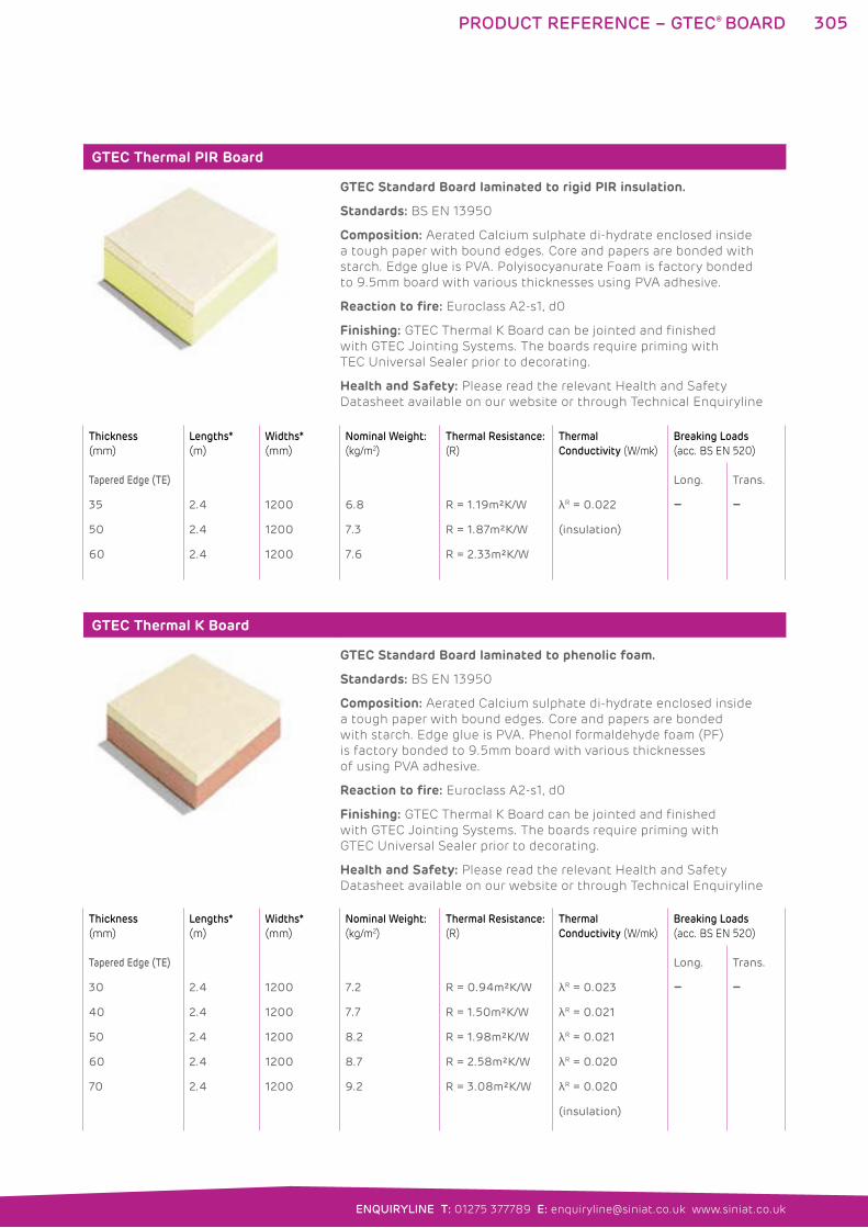
305
ENQUIRYLINE T: 01275 377789 E: [email protected] www.siniat.co.uk
GTEC Thermal PIR Board
GTEC Standard Board laminated to rigid PIR insulation.
Standards: BS EN 13950
Composition: Aerated Calcium sulphate di-hydrate enclosed inside
a tough paper with bound edges. Core and papers are bonded with
starch. Edge glue is PVA. Polyisocyanurate Foam is factory bonded
to 9.5mm board with various thicknesses using PVA adhesive.
Reaction to fire: Euroclass A2-s1, d0
Finishing: GTEC Thermal K Board can be jointed and finished
with GTEC Jointing Systems. The boards require priming with
TEC Universal Sealer prior to decorating.
Health and Safety: Please read the relevant Health and Safety
Datasheet available on our website or through Technical Enquiryline
GTEC Thermal K Board
GTEC Standard Board laminated to phenolic foam.
Standards: BS EN 13950
Composition: Aerated Calcium sulphate di-hydrate enclosed inside
a tough paper with bound edges. Core and papers are bonded
with starch. Edge glue is PVA. Phenol formaldehyde foam (PF)
is factory bonded to 9.5mm board with various thicknesses
of using PVA adhesive.
Reaction to fire: Euroclass A2-s1, d0
Finishing: GTEC Thermal K Board can be jointed and finished
with GTEC Jointing Systems. The boards require priming with
GTEC Universal Sealer prior to decorating.
Health and Safety: Please read the relevant Health and Safety
Datasheet available on our website or through Technical Enquiryline
Thickness
(mm)
Lengths*
(m)
Widths*
(mm)
Nominal Weight:
(kg/m2)
Thermal Resistance:
(R)
Thermal
Conductivity (W/mk)
Breaking Loads
(acc. BS EN 520)
Tapered Edge (TE)
35
50
60
2.4
2.4
2.4
1200
1200
1200
6.8
7.3
7.6
R = 1.19m²K/W
R = 1.87m²K/W
R = 2.33m²K/W
λR = 0.022
(insulation)
Long.
–
Trans.
–
Thickness
(mm)
Lengths*
(m)
Widths*
(mm)
Nominal Weight:
(kg/m2)
Thermal Resistance:
(R)
Thermal
Conductivity (W/mk)
Breaking Loads
(acc. BS EN 520)
Tapered Edge (TE)
30
40
50
60
70
2.4
2.4
2.4
2.4
2.4
1200
1200
1200
1200
1200
7.2
7.7
8.2
8.7
9.2
R = 0.94m²K/W
R = 1.50m²K/W
R = 1.98m²K/W
R = 2.58m²K/W
R = 3.08m²K/W
λR = 0.023
λR = 0.021
λR = 0.021
λR = 0.020
λR = 0.020
(insulation)
Long.
–
Trans.
–
PRODUCT REFERENCE – GTEC® BOARD
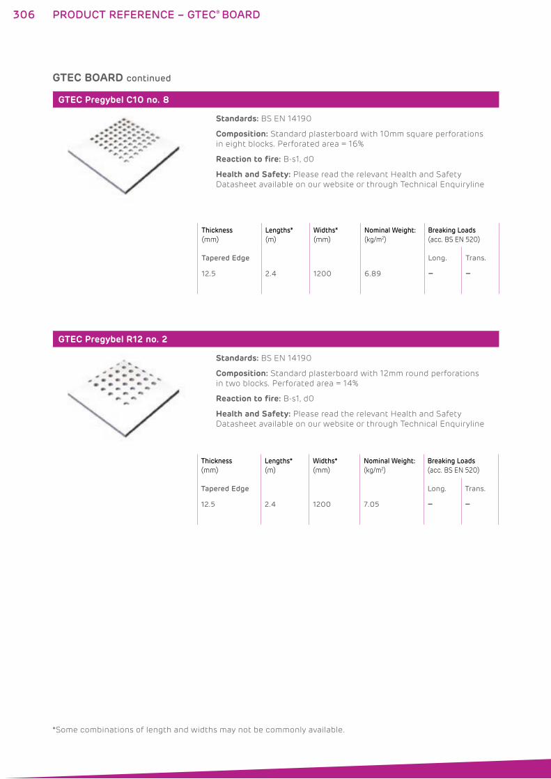
306
GTEC Pregybel C10 no. 8
Standards: BS EN 14190
Composition: Standard plasterboard with 10mm square perforations
in eight blocks. Perforated area = 16%
Reaction to fire: B-s1, d0
Health and Safety: Please read the relevant Health and Safety
Datasheet available on our website or through Technical Enquiryline
GTEC Pregybel R12 no. 2
Standards: BS EN 14190
Composition: Standard plasterboard with 12mm round perforations
in two blocks. Perforated area = 14%
Reaction to fire: B-s1, d0
Health and Safety: Please read the relevant Health and Safety
Datasheet available on our website or through Technical Enquiryline
Thickness
(mm)
Lengths*
(m)
Widths*
(mm)
Nominal Weight:
(kg/m2)
Breaking Loads
(acc. BS EN 520)
Tapered Edge
12.5 2.4 1200 6.89
Long.
–
Trans.
–
Thickness
(mm)
Lengths*
(m)
Widths*
(mm)
Nominal Weight:
(kg/m2)
Breaking Loads
(acc. BS EN 520)
Tapered Edge
12.5 2.4 1200 7.05
Long.
–
Trans.
–
GTEC BOARD continued
PRODUCT REFERENCE – GTEC® BOARD
*Some combinations of length and widths may not be commonly available.
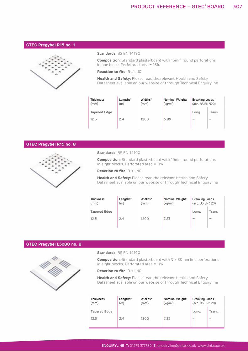
307
ENQUIRYLINE T: 01275 377789 E: [email protected] www.siniat.co.uk
GTEC Pregybel R15 no. 1
Standards: BS EN 14190
Composition: Standard plasterboard with 15mm round perforations
in one block. Perforated area = 16%
Reaction to fire: B-s1, d0
Health and Safety: Please read the relevant Health and Safety
Datasheet available on our website or through Technical Enquiryline
GTEC Pregybel R15 no. 8
Standards: BS EN 14190
Composition: Standard plasterboard with 15mm round perforations
in eight blocks. Perforated area = 11%
Reaction to fire: B-s1, d0
Health and Safety: Please read the relevant Health and Safety
Datasheet available on our website or through Technical Enquiryline
GTEC Pregybel L5x80 no. 8
Standards: BS EN 14190
Composition: Standard plasterboard with 5 x 80mm line perforations
in eight blocks. Perforated area = 11%
Reaction to fire: B-s1, d0
Health and Safety: Please read the relevant Health and Safety
Datasheet available on our website or through Technical Enquiryline
Thickness
(mm)
Lengths*
(m)
Widths*
(mm)
Nominal Weight:
(kg/m2)
Breaking Loads
(acc. BS EN 520)
Tapered Edge
12.5 2.4 1200 6.89
Long.
–
Trans.
–
Thickness
(mm)
Lengths*
(m)
Widths*
(mm)
Nominal Weight:
(kg/m2)
Breaking Loads
(acc. BS EN 520)
Tapered Edge
12.5 2.4 1200 7.23
Long.
–
Trans.
–
Thickness
(mm)
Lengths*
(m)
Widths*
(mm)
Nominal Weight:
(kg/m2)
Breaking Loads
(acc. BS EN 520)
Tapered Edge
12.5 2.4 1200 7.23
Long.
–
Trans.
–
PRODUCT REFERENCE – GTEC® BOARD
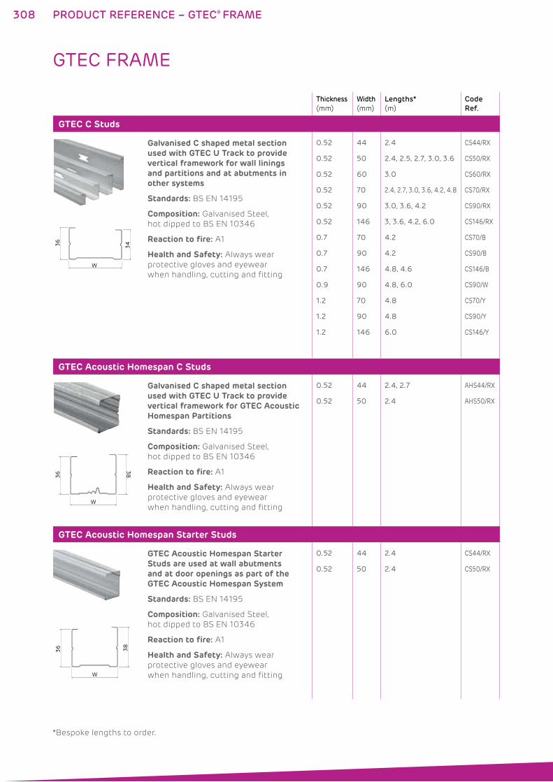
308
Thickness
(mm)
Width
(mm)
Lengths*
(m)
Code
Ref.
GTEC C Studs
W
34 36
Galvanised C shaped metal section used with GTEC U Track to provide vertical framework for wall linings and partitions and at abutments in other systems
Standards: BS EN 14195
Composition: Galvanised Steel,
hot dipped to BS EN 10346
Reaction to fire: A1
Health and Safety: Always wear
protective gloves and eyewear
when handling, cutting and fitting
0.52
0.52
0.52
0.52
0.52
0.52
0.7
0.7
0.7
0.9
1.2
1.2
1.2
44
50
60
70
90
146
70
90
146
90
70
90
146
2.4
2.4, 2.5, 2.7, 3.0, 3.6
3.0
2.4, 2.7, 3.0, 3.6, 4.2, 4.8
3.0, 3.6, 4.2
3, 3.6, 4.2, 6.0
4.2
4.2
4.8, 4.6
4.8, 6.0
4.8
4.8
6.0
CS44/RX
CS50/RX
CS60/RX
CS70/RX
CS90/RX
CS146/RX
CS70/B
CS90/B
CS146/B
CS90/W
CS70/Y
CS90/Y
CS146/Y
GTEC Acoustic Homespan C Studs
W
38 3
6
Galvanised C shaped metal section used with GTEC U Track to provide vertical framework for GTEC Acoustic Homespan Partitions
Standards: BS EN 14195
Composition: Galvanised Steel,
hot dipped to BS EN 10346
Reaction to fire: A1
Health and Safety: Always wear
protective gloves and eyewear
when handling, cutting and fitting
0.52
0.52
44
50
2.4, 2.7
2.4
AHS44/RX
AHS50/RX
GTEC Acoustic Homespan Starter Studs
W
38
36
GTEC Acoustic Homespan Starter Studs are used at wall abutments and at door openings as part of the GTEC Acoustic Homespan System
Standards: BS EN 14195
Composition: Galvanised Steel,
hot dipped to BS EN 10346
Reaction to fire: A1
Health and Safety: Always wear
protective gloves and eyewear
when handling, cutting and fitting
0.52
0.52
44
50
2.4
2.4
CS44/RX
CS50/RX
GTEC FRAME
PRODUCT REFERENCE – GTEC® FRAME
*Bespoke lengths to order.
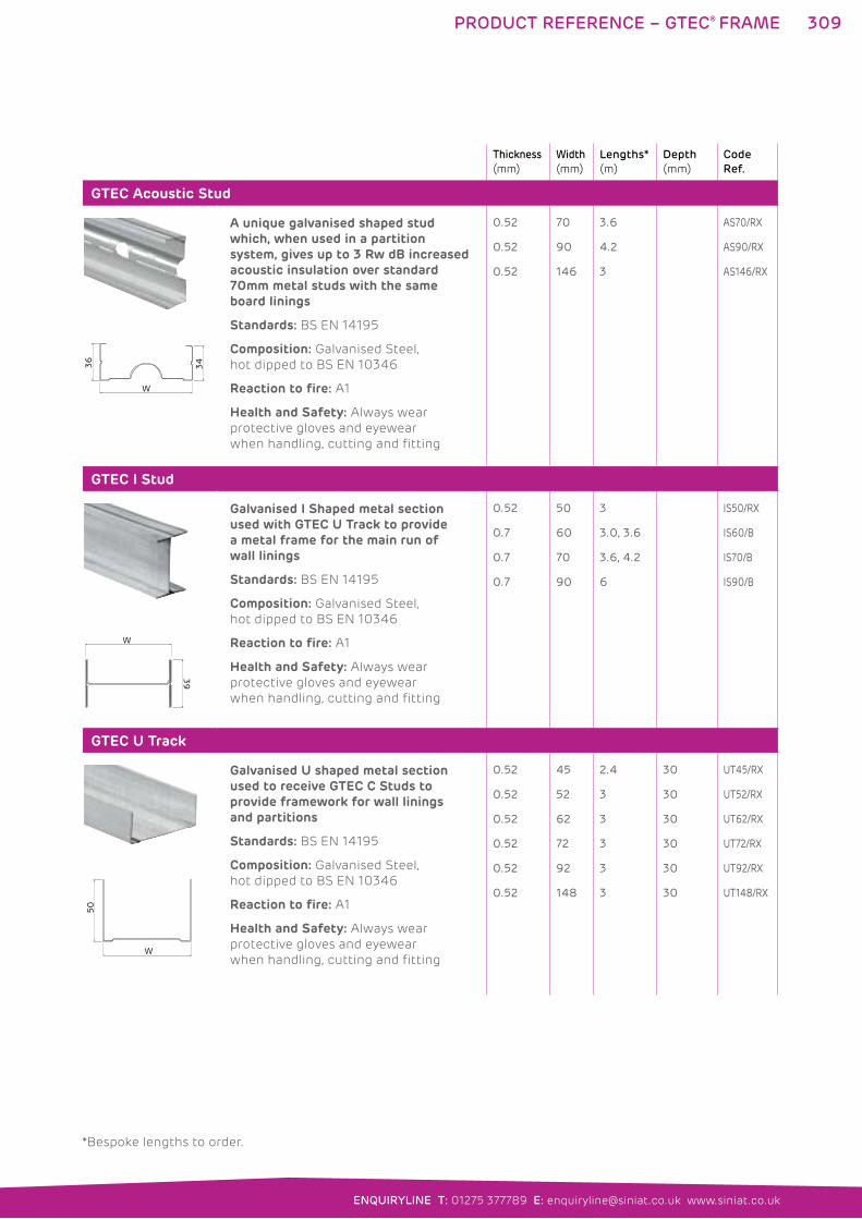
309
ENQUIRYLINE T: 01275 377789 E: [email protected] www.siniat.co.uk
Thickness
(mm)
Width
(mm)
Lengths*
(m)
Depth
(mm)
Code
Ref.
GTEC Acoustic Stud
W
34
36
A unique galvanised shaped stud which, when used in a partition system, gives up to 3 Rw dB increased acoustic insulation over standard 70mm metal studs with the same board linings
Standards: BS EN 14195
Composition: Galvanised Steel,
hot dipped to BS EN 10346
Reaction to fire: A1
Health and Safety: Always wear
protective gloves and eyewear
when handling, cutting and fitting
0.52
0.52
0.52
70
90
146
3.6
4.2
3
AS70/RX
AS90/RX
AS146/RX
GTEC I Stud
W
39
Galvanised I Shaped metal section used with GTEC U Track to provide a metal frame for the main run of wall linings
Standards: BS EN 14195
Composition: Galvanised Steel,
hot dipped to BS EN 10346
Reaction to fire: A1
Health and Safety: Always wear
protective gloves and eyewear
when handling, cutting and fitting
0.52
0.7
0.7
0.7
50
60
70
90
3
3.0, 3.6
3.6, 4.2
6
IS50/RX
IS60/B
IS70/B
IS90/B
GTEC U Track
W
50
Galvanised U shaped metal section used to receive GTEC C Studs to provide framework for wall linings and partitions
Standards: BS EN 14195
Composition: Galvanised Steel,
hot dipped to BS EN 10346
Reaction to fire: A1
Health and Safety: Always wear
protective gloves and eyewear
when handling, cutting and fitting
0.52
0.52
0.52
0.52
0.52
0.52
45
52
62
72
92
148
2.4
3
3
3
3
3
30
30
30
30
30
30
UT45/RX
UT52/RX
UT62/RX
UT72/RX
UT92/RX
UT148/RX
PRODUCT REFERENCE – GTEC® FRAME
*Bespoke lengths to order.
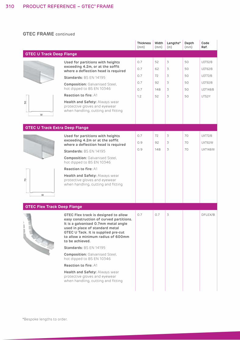
310
Thickness
(mm)
Width
(mm)
Lengths*
(m)
Depth
(mm)
Code
Ref.
GTEC U Track Deep Flange
W
50
Used for partitions with heights exceeding 4.2m, or at the soffit where a deflection head is required
Standards: BS EN 14195
Composition: Galvanised Steel,
hot dipped to BS EN 10346
Reaction to fire: A1
Health and Safety: Always wear
protective gloves and eyewear
when handling, cutting and fitting
0.7
0.7
0.7
0.7
0.7
1.2
52
62
72
92
148
52
3
3
3
3
3
3
50
50
50
50
50
50
UDT52/B
UDT62/B
UDT72/B
UDT92/B
UDT148/B
UT52/Y
GTEC U Track Extra Deep Flange
W
70
Used for partitions with heights exceeding 4.2m or at the soffit where a deflection head is required
Standards: BS EN 14195
Composition: Galvanised Steel,
hot dipped to BS EN 10346
Reaction to fire: A1
Health and Safety: Always wear
protective gloves and eyewear
when handling, cutting and fitting
0.7
0.9
0.9
72
92
148
3
3
3
70
70
70
UXT72/B
UXT92/W
UXT148/W
GTEC Flex Track Deep Flange
GTEC Flex track is designed to allow easy construction of curved partitions. It is a galvanised 0.7mm metal angle used in place of standard metal GTEC U Tack. It is supplied pre-cut to allow a minimum radius of 600mm to be achieved.
Standards: BS EN 14195
Composition: Galvanised Steel,
hot dipped to BS EN 10346
Reaction to fire: A1
Health and Safety: Always wear
protective gloves and eyewear
when handling, cutting and fitting
0.7 0.7 3 DFLEX/B
GTEC FRAME continued
PRODUCT REFERENCE – GTEC® FRAME
*Bespoke lengths to order.
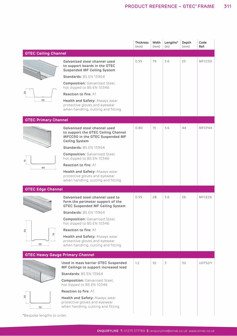
311
ENQUIRYLINE T: 01275 377789 E: [email protected] www.siniat.co.uk
Thickness
(mm)
Width
(mm)
Lengths*
(m)
Depth
(mm)
Code
Ref.
GTEC Ceiling Channel
25
50
Galvanised steel channel used to support boards in the GTEC Suspended MF Ceiling System
Standards: BS EN 13964
Composition: Galvanised Steel,
hot dipped to BS EN 10346
Reaction to fire: A1
Health and Safety: Always wear
protective gloves and eyewear
when handling, cutting and fitting
0.55 79 3.6 25 MFCC50
GTEC Primary Channel
44
15
Galvanised steel channel used to support the GTEC Ceiling Channel MFCC50 in the GTEC Suspended MF Ceiling System
Standards: BS EN 13964
Composition: Galvanised Steel,
hot dipped to BS EN 10346
Reaction to fire: A1
Health and Safety: Always wear
protective gloves and eyewear
when handling, cutting and fitting
0.80 15 3.6 44 MFCP44
GTEC Edge Channel
26
19
30
Galvanised steel channel used to form the perimeter support of the GTEC Suspended MF Ceiling System
Standards: BS EN 13964
Composition: Galvanised Steel,
hot dipped to BS EN 10346
Reaction to fire: A1
Health and Safety: Always wear
protective gloves and eyewear
when handling, cutting and fitting
0.55 28 3.6 26 MFCE26
GTEC Heavy Gauge Primary Channel
52
30
Used in mass barrier GTEC Suspended MF Ceilings to support increased load
Standards: BS EN 13964
Composition: Galvanised Steel,
hot dipped to BS EN 10346
Reaction to fire: A1
Health and Safety: Always wear
protective gloves and eyewear
when handling, cutting and fitting
1.2
52
3
30
UDT52/Y
PRODUCT REFERENCE – GTEC® FRAME
*Bespoke lengths to order.
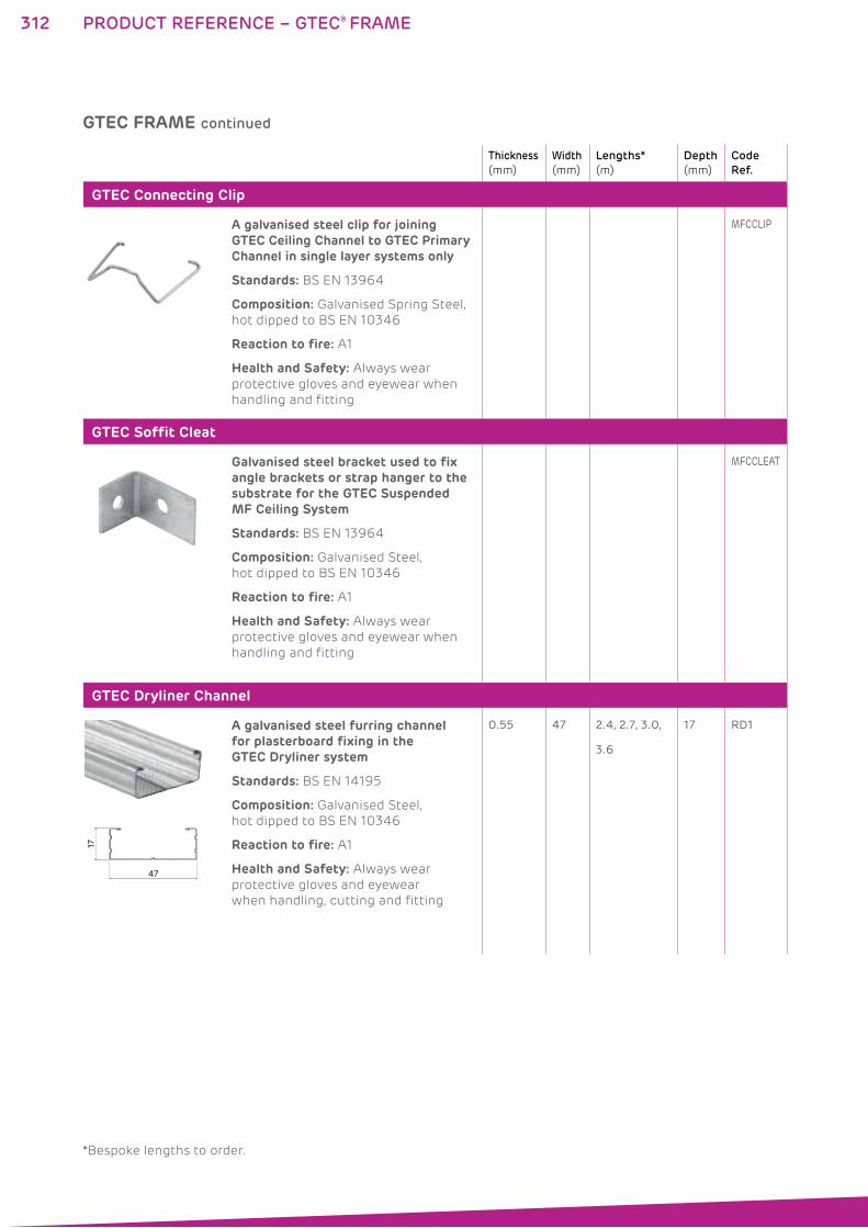
312
Thickness
(mm)
Width
(mm)
Lengths*
(m)
Depth
(mm)
Code
Ref.
GTEC Connecting Clip
A galvanised steel clip for joining GTEC Ceiling Channel to GTEC Primary Channel in single layer systems only
Standards: BS EN 13964
Composition: Galvanised Spring Steel,
hot dipped to BS EN 10346
Reaction to fire: A1
Health and Safety: Always wear
protective gloves and eyewear when
handling and fitting
MFCCLIP
GTEC Soffit Cleat
Galvanised steel bracket used to fix angle brackets or strap hanger to the substrate for the GTEC Suspended MF Ceiling System
Standards: BS EN 13964
Composition: Galvanised Steel,
hot dipped to BS EN 10346
Reaction to fire: A1
Health and Safety: Always wear
protective gloves and eyewear when
handling and fitting
MFCCLEAT
GTEC Dryliner Channel
47
17
A galvanised steel furring channel for plasterboard fixing in the GTEC Dryliner system
Standards: BS EN 14195
Composition: Galvanised Steel,
hot dipped to BS EN 10346
Reaction to fire: A1
Health and Safety: Always wear
protective gloves and eyewear
when handling, cutting and fitting
0.55 47 2.4, 2.7, 3.0,
3.6
17 RD1
GTEC FRAME continued
PRODUCT REFERENCE – GTEC® FRAME
*Bespoke lengths to order.
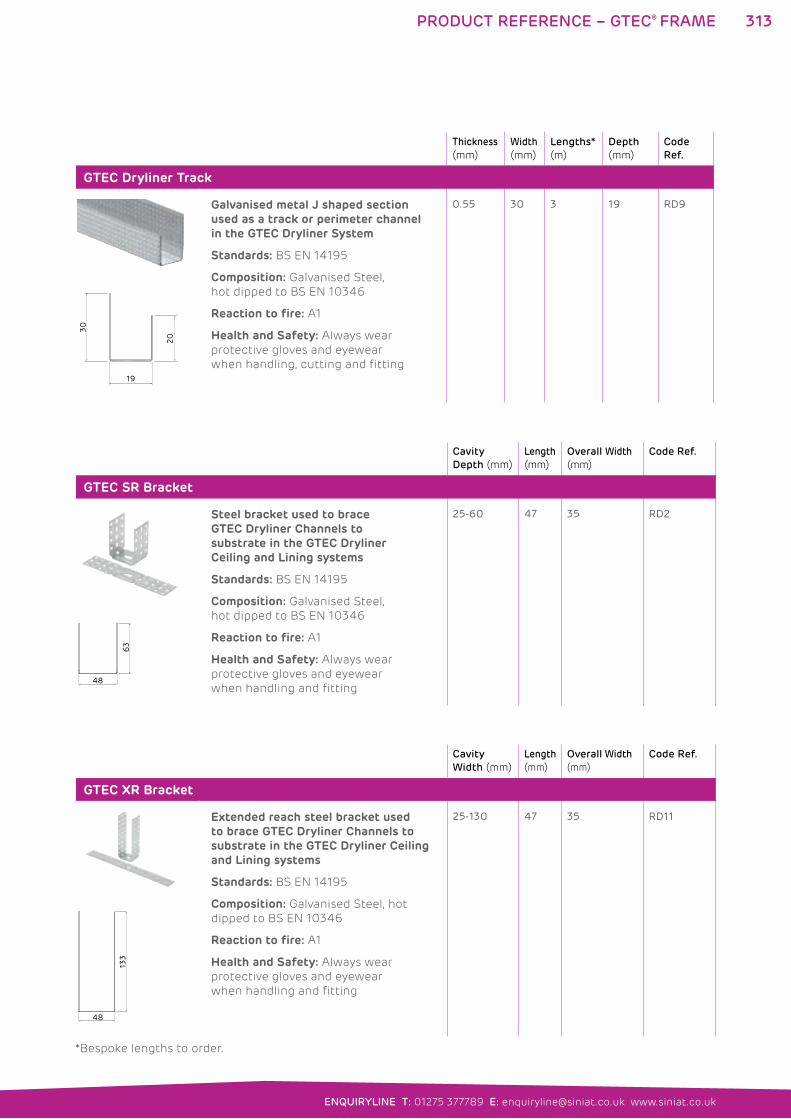
313
ENQUIRYLINE T: 01275 377789 E: [email protected] www.siniat.co.uk
Thickness
(mm)
Width
(mm)
Lengths*
(m)
Depth
(mm)
Code
Ref.
GTEC Dryliner Track
19
30
20
Galvanised metal J shaped section used as a track or perimeter channel in the GTEC Dryliner System
Standards: BS EN 14195
Composition: Galvanised Steel,
hot dipped to BS EN 10346
Reaction to fire: A1
Health and Safety: Always wear
protective gloves and eyewear
when handling, cutting and fitting
0.55 30 3 19 RD9
PRODUCT REFERENCE – GTEC® FRAME
*Bespoke lengths to order.
Cavity
Depth (mm)
Length
(mm)
Overall Width
(mm)
Code Ref.
GTEC SR Bracket
63
48
Steel bracket used to brace GTEC Dryliner Channels to substrate in the GTEC Dryliner Ceiling and Lining systems
Standards: BS EN 14195
Composition: Galvanised Steel,
hot dipped to BS EN 10346
Reaction to fire: A1
Health and Safety: Always wear
protective gloves and eyewear
when handling and fitting
25-60 47 35 RD2
Cavity
Width (mm)
Length
(mm)
Overall Width
(mm)
Code Ref.
GTEC XR Bracket
133
48
Extended reach steel bracket used to brace GTEC Dryliner Channels to substrate in the GTEC Dryliner Ceiling and Lining systems
Standards: BS EN 14195
Composition: Galvanised Steel, hot
dipped to BS EN 10346
Reaction to fire: A1
Health and Safety: Always wear
protective gloves and eyewear
when handling and fitting
25-130 47 35 RD11
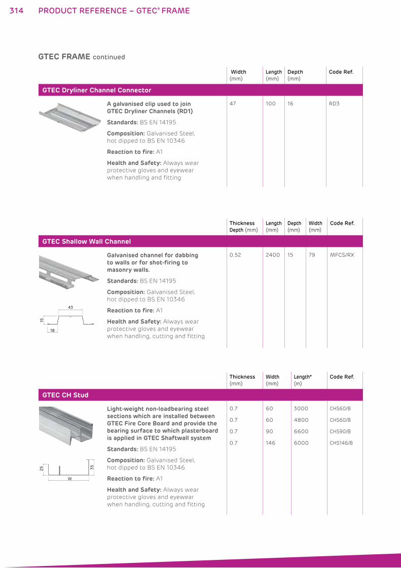
314
Width
(mm)
Length
(mm)
Depth
(mm)
Code Ref.
GTEC Dryliner Channel Connector
A galvanised clip used to join GTEC Dryliner Channels (RD1)
Standards: BS EN 14195
Composition: Galvanised Steel,
hot dipped to BS EN 10346
Reaction to fire: A1
Health and Safety: Always wear
protective gloves and eyewear
when handling and fitting
47 100 16 RD3
Thickness
Depth (mm)
Length
(mm)
Depth
(mm)
Width
(mm)
Code Ref.
GTEC Shallow Wall Channel
15
18
43
Galvanised channel for dabbing to walls or for shot-firing to masonry walls.
Standards: BS EN 14195
Composition: Galvanised Steel,
hot dipped to BS EN 10346
Reaction to fire: A1
Health and Safety: Always wear
protective gloves and eyewear
when handling, cutting and fitting
0.52 2400 15 79 MFCS/RX
Thickness
(mm)
Width
(mm)
Length*
(m)
Code Ref.
GTEC CH Stud
W
35
25
Light-weight non-loadbearing steel sections which are installed between GTEC Fire Core Board and provide the bearing surface to which plasterboard is applied in GTEC Shaftwall system
Standards: BS EN 14195
Composition: Galvanised Steel,
hot dipped to BS EN 10346
Reaction to fire: A1
Health and Safety: Always wear
protective gloves and eyewear
when handling, cutting and fitting
0.7
0.7
0.7
0.7
60
60
90
146
3000
4800
6600
6000
CHS60/B
CHS60/B
CHS90/B
CHS146/B
GTEC FRAME continued
PRODUCT REFERENCE – GTEC® FRAME
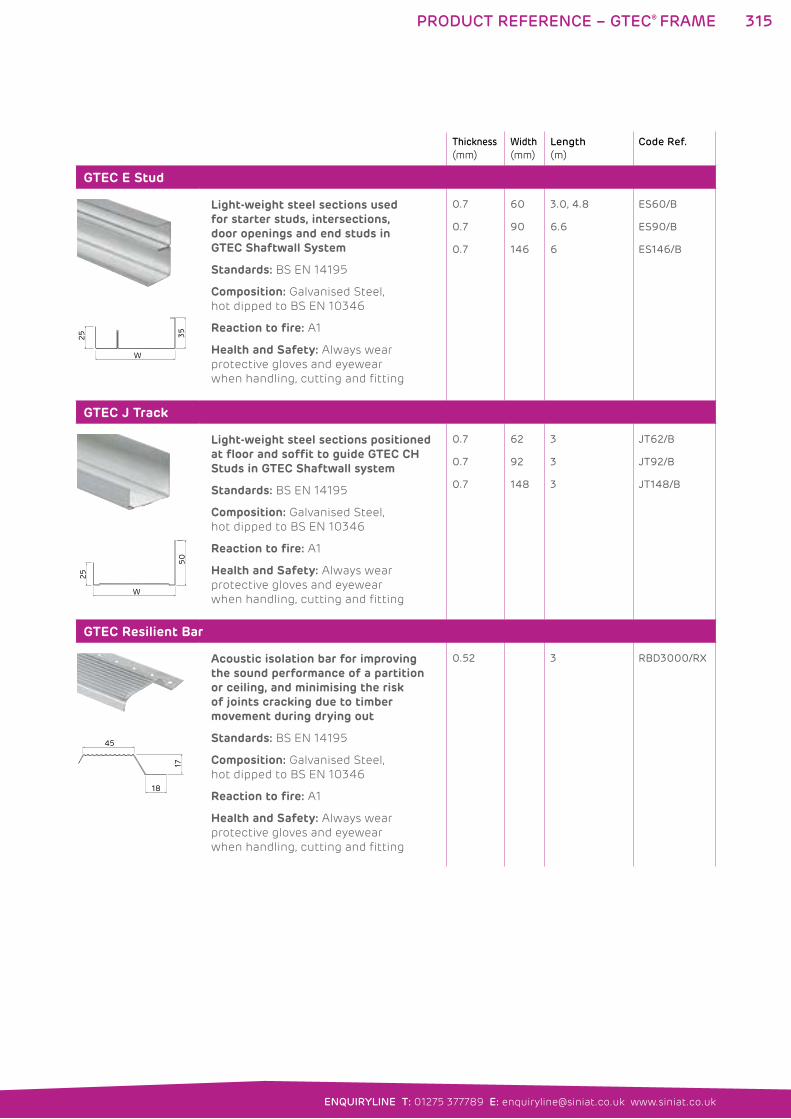
315
ENQUIRYLINE T: 01275 377789 E: [email protected] www.siniat.co.uk
PRODUCT REFERENCE – GTEC® FRAME
Thickness
(mm)
Width
(mm)
Length
(m)
Code Ref.
GTEC E Stud
W
35
25
Light-weight steel sections used for starter studs, intersections, door openings and end studs in GTEC Shaftwall System
Standards: BS EN 14195
Composition: Galvanised Steel,
hot dipped to BS EN 10346
Reaction to fire: A1
Health and Safety: Always wear
protective gloves and eyewear
when handling, cutting and fitting
0.7
0.7
0.7
60
90
146
3.0, 4.8
6.6
6
ES60/B
ES90/B
ES146/B
GTEC J Track
W
50
25
Light-weight steel sections positioned at floor and soffit to guide GTEC CH Studs in GTEC Shaftwall system
Standards: BS EN 14195
Composition: Galvanised Steel,
hot dipped to BS EN 10346
Reaction to fire: A1
Health and Safety: Always wear
protective gloves and eyewear
when handling, cutting and fitting
0.7
0.7
0.7
62
92
148
3
3
3
JT62/B
JT92/B
JT148/B
GTEC Resilient Bar
18
17
45
Acoustic isolation bar for improving the sound performance of a partition or ceiling, and minimising the risk of joints cracking due to timber movement during drying out
Standards: BS EN 14195
Composition: Galvanised Steel,
hot dipped to BS EN 10346
Reaction to fire: A1
Health and Safety: Always wear
protective gloves and eyewear
when handling, cutting and fitting
0.52 3 RBD3000/RX
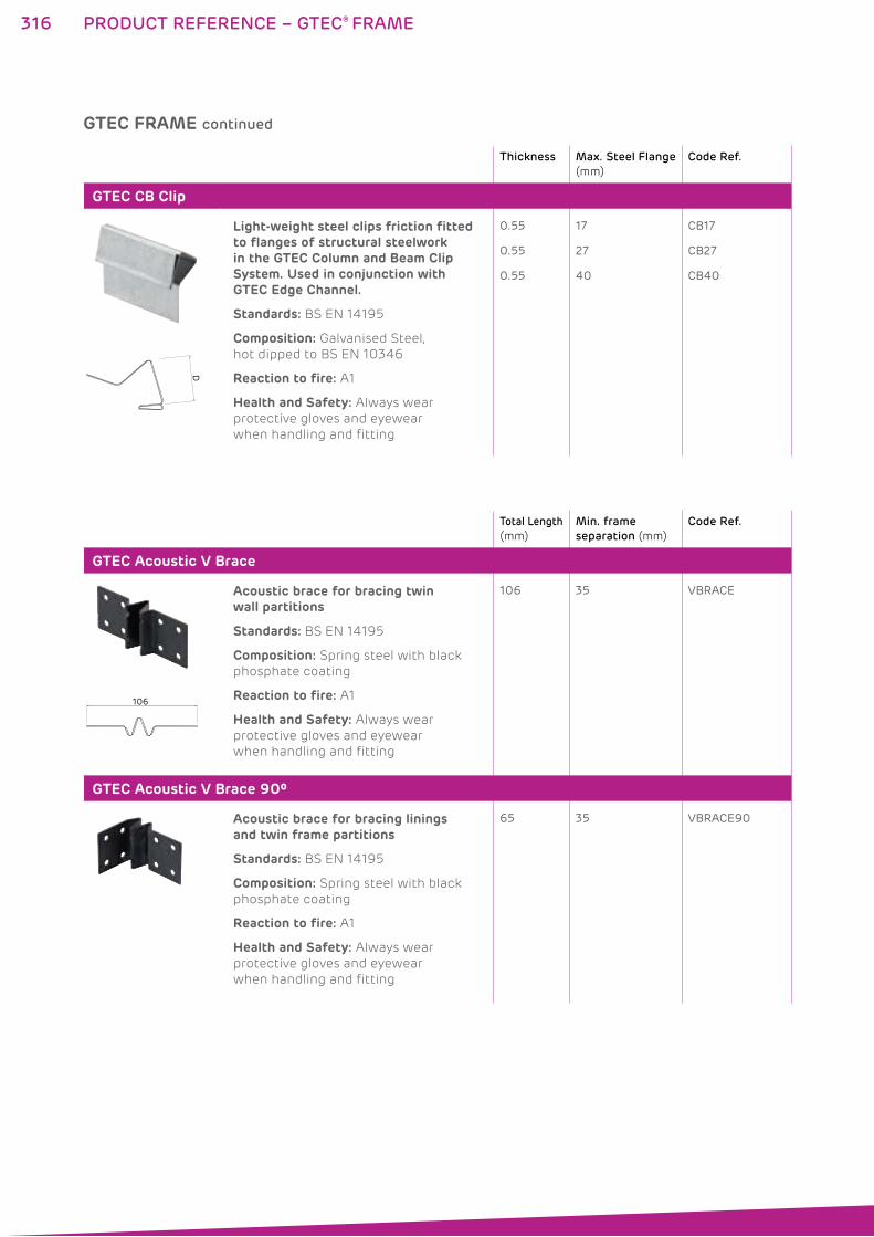
316
Thickness Max. Steel Flange
(mm)
Code Ref.
GTEC CB Clip
D
Light-weight steel clips friction fitted to flanges of structural steelwork in the GTEC Column and Beam Clip System. Used in conjunction with GTEC Edge Channel.
Standards: BS EN 14195
Composition: Galvanised Steel,
hot dipped to BS EN 10346
Reaction to fire: A1
Health and Safety: Always wear
protective gloves and eyewear
when handling and fitting
0.55
0.55
0.55
17
27
40
CB17
CB27
CB40
Total Length
(mm)
Min. frame
separation (mm)
Code Ref.
GTEC Acoustic V Brace
106
Acoustic brace for bracing twin wall partitions
Standards: BS EN 14195
Composition: Spring steel with black
phosphate coating
Reaction to fire: A1
Health and Safety: Always wear
protective gloves and eyewear
when handling and fitting
106 35 VBRACE
GTEC Acoustic V Brace 90º
Acoustic brace for bracing linings and twin frame partitions
Standards: BS EN 14195
Composition: Spring steel with black
phosphate coating
Reaction to fire: A1
Health and Safety: Always wear
protective gloves and eyewear
when handling and fitting
65 35 VBRACE90
GTEC FRAME continued
PRODUCT REFERENCE – GTEC® FRAME
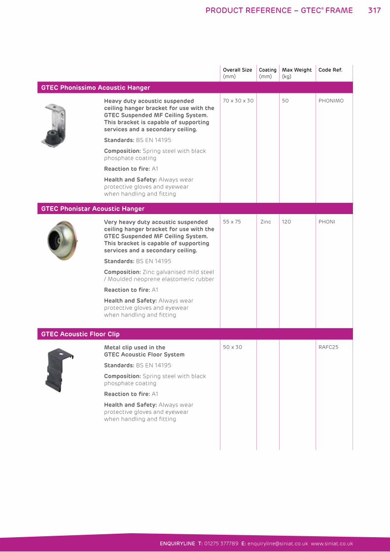
317
ENQUIRYLINE T: 01275 377789 E: [email protected] www.siniat.co.uk
PRODUCT REFERENCE – GTEC® FRAME
Overall Size
(mm)
Coating
(mm)
Max Weight
(kg)
Code Ref.
GTEC Phonissimo Acoustic Hanger
Heavy duty acoustic suspended ceiling hanger bracket for use with the GTEC Suspended MF Ceiling System. This bracket is capable of supporting services and a secondary ceiling.
Standards: BS EN 14195
Composition: Spring steel with black
phosphate coating
Reaction to fire: A1
Health and Safety: Always wear
protective gloves and eyewear
when handling and fitting
70 x 30 x 30 50 PHONIMO
GTEC Phonistar Acoustic Hanger
Very heavy duty acoustic suspended ceiling hanger bracket for use with the GTEC Suspended MF Ceiling System. This bracket is capable of supporting services and a secondary ceiling.
Standards: BS EN 14195
Composition: Zinc galvanised mild steel
/ Moulded neoprene elastomeric rubber
Reaction to fire: A1
Health and Safety: Always wear
protective gloves and eyewear
when handling and fitting
55 x 75 Zinc 120 PHONI
GTEC Acoustic Floor Clip
Metal clip used in the GTEC Acoustic Floor System
Standards: BS EN 14195
Composition: Spring steel with black
phosphate coating
Reaction to fire: A1
Health and Safety: Always wear
protective gloves and eyewear
when handling and fitting
50 x 30 RAFC25
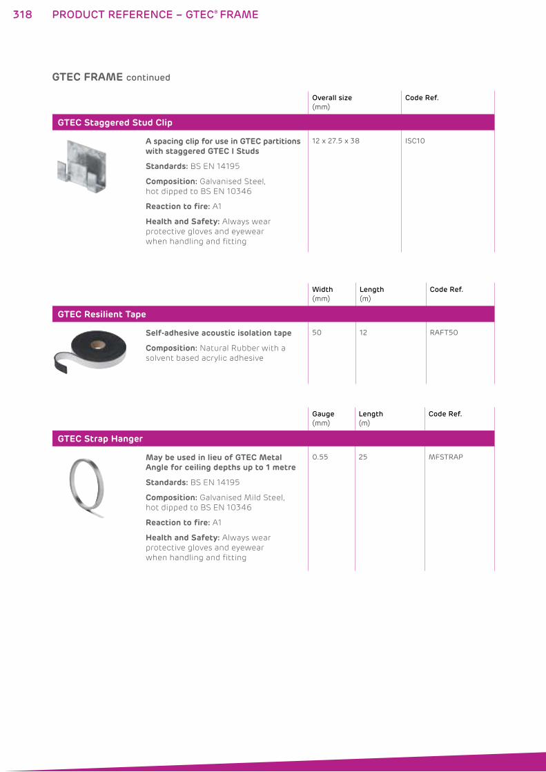
318
Overall size
(mm)
Code Ref.
GTEC Staggered Stud Clip
A spacing clip for use in GTEC partitions with staggered GTEC I Studs
Standards: BS EN 14195
Composition: Galvanised Steel,
hot dipped to BS EN 10346
Reaction to fire: A1
Health and Safety: Always wear
protective gloves and eyewear
when handling and fitting
12 x 27.5 x 38 ISC10
Width
(mm)
Length
(m)
Code Ref.
GTEC Resilient Tape
Self-adhesive acoustic isolation tape
Composition: Natural Rubber with a
solvent based acrylic adhesive
50 12 RAFT50
Gauge
(mm)
Length
(m)
Code Ref.
GTEC Strap Hanger
May be used in lieu of GTEC Metal Angle for ceiling depths up to 1 metre
Standards: BS EN 14195
Composition: Galvanised Mild Steel,
hot dipped to BS EN 10346
Reaction to fire: A1
Health and Safety: Always wear
protective gloves and eyewear
when handling and fitting
0.55 25 MFSTRAP
GTEC FRAME continued
PRODUCT REFERENCE – GTEC® FRAME
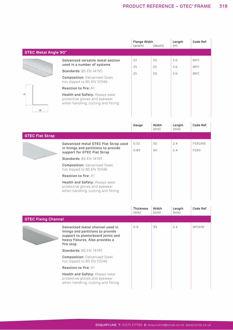
319
ENQUIRYLINE T: 01275 377789 E: [email protected] www.siniat.co.uk
PRODUCT REFERENCE – GTEC® FRAME
Flange Width
(width) (depth)
Length
(m)
Code Ref.
GTEC Metal Angle 90°
W
D
Galvanised versatile metal section used in a number of systems
Standards: BS EN 14195
Composition: Galvanised Steel,
hot dipped to BS EN 10346
Reaction to fire: A1
Health and Safety: Always wear
protective gloves and eyewear
when handling, cutting and fitting
23
25
25
30
25
50
3.6
3.6
3.6
MFC
MFC
MFC
Gauge Width
(mm)
Length
(mm)
Code Ref.
GTEC Flat Strap
Galvanised metal GTEC Flat Strap used in linings and partitions to provide support for GTEC Flat Strap
Standards: BS EN 14195
Composition: Galvanised Steel,
hot dipped to BS EN 10346
Reaction to fire: A1
Health and Safety: Always wear
protective gloves and eyewear
when handling, cutting and fitting
0.52
0.85
50
90
2.4
2.4
FS50/RX
FS90
Thickness
(mm)
Width
(mm)
Length
(mm)
Code Ref.
GTEC Fixing Channel
Galvanised metal channel used in linings and partitions to provide support to plasterboard joints and heavy fixtures. Also provides a fire stop
Standards: BS EN 14195
Composition: Galvanised Steel,
hot dipped to BS EN 10346
Reaction to fire: A1
Health and Safety: Always wear
protective gloves and eyewear
when handling, cutting and fitting
0.9 99 2.4 MFIX/W
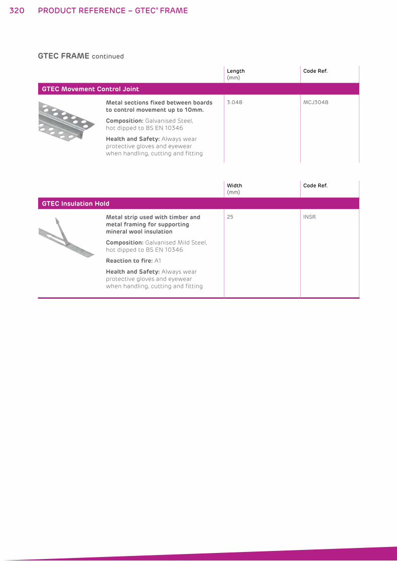
320
Length
(mm)
Code Ref.
GTEC Movement Control Joint
Metal sections fixed between boards to control movement up to 10mm.
Composition: Galvanised Steel,
hot dipped to BS EN 10346
Health and Safety: Always wear
protective gloves and eyewear
when handling, cutting and fitting
3.048 MCJ3048
Width
(mm)
Code Ref.
GTEC Insulation Hold
Metal strip used with timber and metal framing for supporting mineral wool insulation
Composition: Galvanised Mild Steel,
hot dipped to BS EN 10346
Reaction to fire: A1
Health and Safety: Always wear
protective gloves and eyewear
when handling, cutting and fitting
25 INSR
GTEC FRAME continued
PRODUCT REFERENCE – GTEC® FRAME
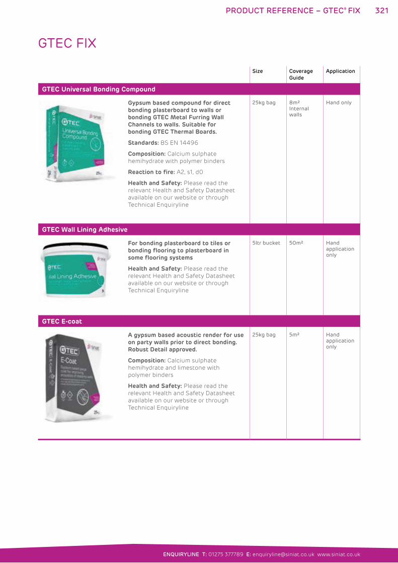
321
ENQUIRYLINE T: 01275 377789 E: [email protected] www.siniat.co.uk
PRODUCT REFERENCE – GTEC® FIX
Size Coverage
Guide
Application
GTEC Universal Bonding Compound
Gypsum based compound for direct bonding plasterboard to walls or bonding GTEC Metal Furring Wall Channels to walls. Suitable for bonding GTEC Thermal Boards.
Standards: BS EN 14496
Composition: Calcium sulphate
hemihydrate with polymer binders
Reaction to fire: A2, s1, d0
Health and Safety: Please read the
relevant Health and Safety Datasheet
available on our website or through
Technical Enquiryline
25kg bag 8m² Internal walls
Hand only
GTEC Wall Lining Adhesive
For bonding plasterboard to tiles or bonding flooring to plasterboard in some flooring systems
Health and Safety: Please read the
relevant Health and Safety Datasheet
available on our website or through
Technical Enquiryline
5ltr bucket 50m² Hand application only
GTEC E-coat
A gypsum based acoustic render for use on party walls prior to direct bonding. Robust Detail approved.
Composition: Calcium sulphate
hemihydrate and limestone with
polymer binders
Health and Safety: Please read the
relevant Health and Safety Datasheet
available on our website or through
Technical Enquiryline
25kg bag 5m² Hand application only
GTEC FIX
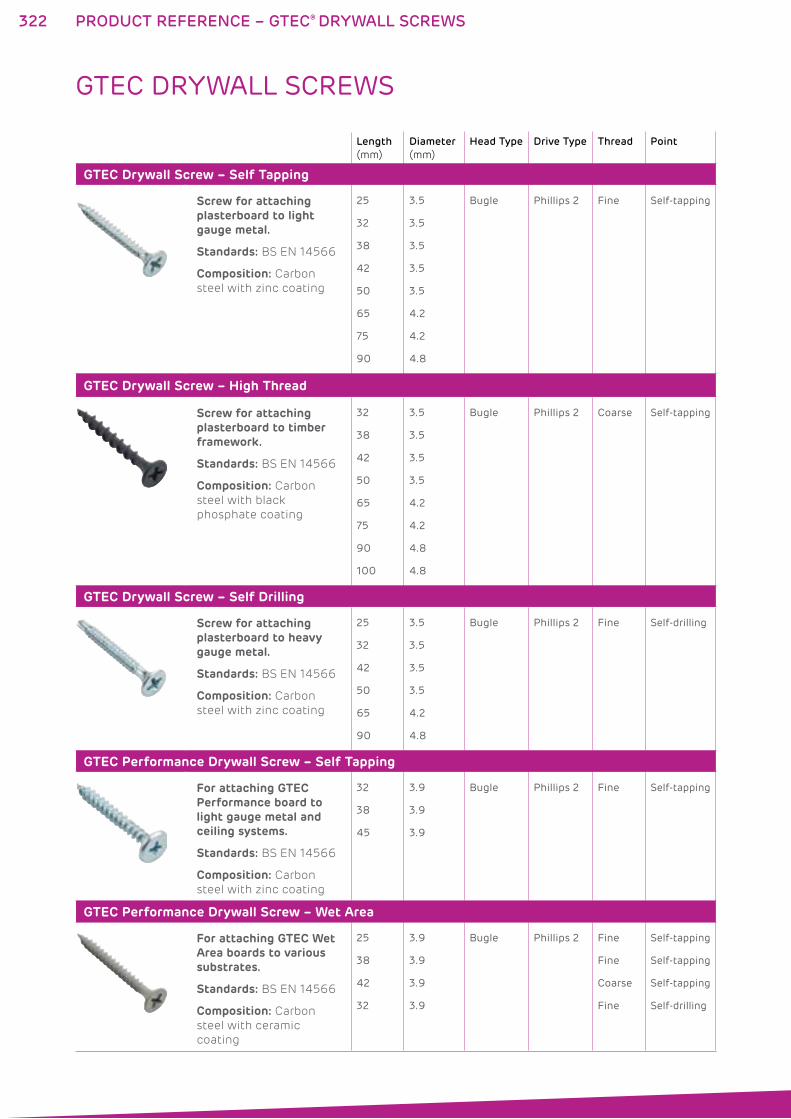
322
GTEC DRYWALL SCREWS
PRODUCT REFERENCE – GTEC® DRYWALL SCREWS
Length
(mm)
Diameter
(mm)
Head Type Drive Type Thread Point
GTEC Drywall Screw – Self Tapping
Screw for attaching plasterboard to light gauge metal.
Standards: BS EN 14566
Composition: Carbon
steel with zinc coating
25
32
38
42
50
65
75
90
3.5
3.5
3.5
3.5
3.5
4.2
4.2
4.8
Bugle Phillips 2 Fine Self-tapping
GTEC Drywall Screw – High Thread
Screw for attaching plasterboard to timber framework.
Standards: BS EN 14566
Composition: Carbon
steel with black
phosphate coating
32
38
42
50
65
75
90
100
3.5
3.5
3.5
3.5
4.2
4.2
4.8
4.8
Bugle Phillips 2 Coarse Self-tapping
GTEC Drywall Screw – Self Drilling
Screw for attaching plasterboard to heavy gauge metal.
Standards: BS EN 14566
Composition: Carbon
steel with zinc coating
25
32
42
50
65
90
3.5
3.5
3.5
3.5
4.2
4.8
Bugle Phillips 2 Fine Self-drilling
GTEC Performance Drywall Screw – Self Tapping
For attaching GTEC Performance board to light gauge metal and ceiling systems.
Standards: BS EN 14566
Composition: Carbon
steel with zinc coating
32
38
45
3.9
3.9
3.9
Bugle Phillips 2 Fine Self-tapping
GTEC Performance Drywall Screw – Wet Area
For attaching GTEC Wet Area boards to various substrates.
Standards: BS EN 14566
Composition: Carbon
steel with ceramic
coating
25
38
42
32
3.9
3.9
3.9
3.9
Bugle Phillips 2 Fine
Fine
Coarse
Fine
Self-tapping
Self-tapping
Self-tapping
Self-drilling
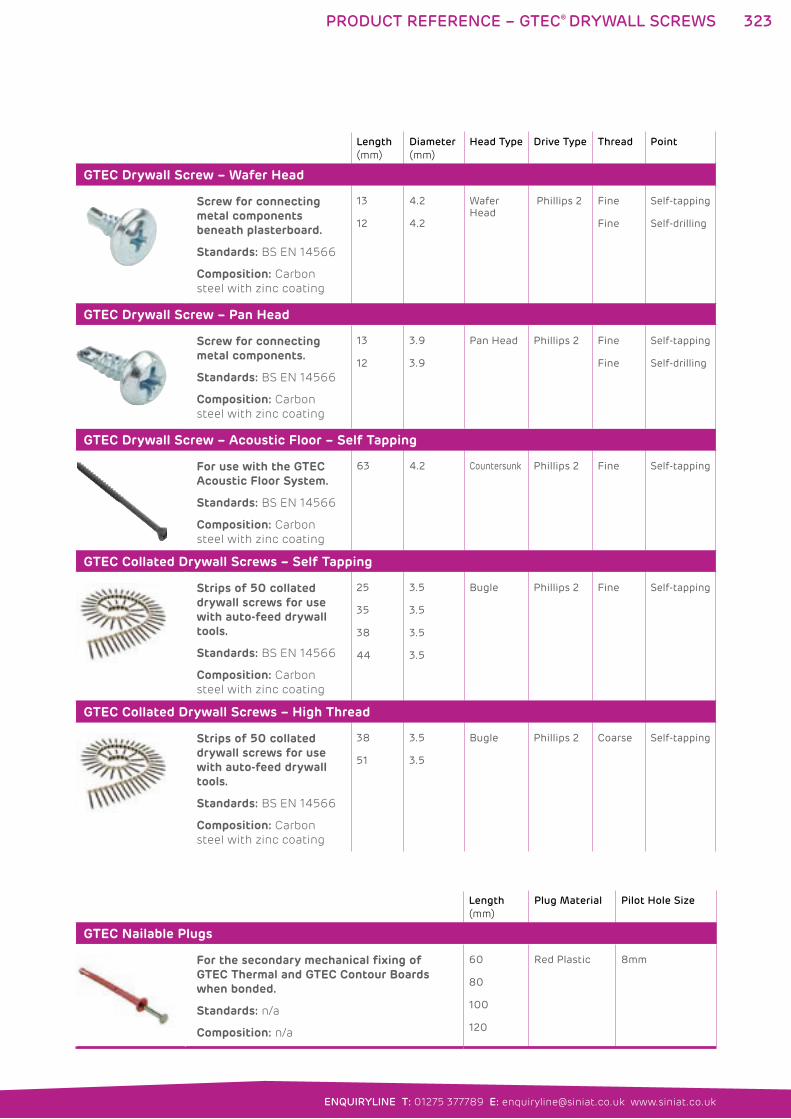
323
ENQUIRYLINE T: 01275 377789 E: [email protected] www.siniat.co.uk
PRODUCT REFERENCE – GTEC® DRYWALL SCREWS
Length
(mm)
Diameter
(mm)
Head Type Drive Type Thread Point
GTEC Drywall Screw – Wafer Head
Screw for connecting metal components beneath plasterboard.
Standards: BS EN 14566
Composition: Carbon
steel with zinc coating
13
12
4.2
4.2
Wafer Head
Phillips 2 Fine
Fine
Self-tapping
Self-drilling
GTEC Drywall Screw – Pan Head
Screw for connecting metal components.
Standards: BS EN 14566
Composition: Carbon
steel with zinc coating
13
12
3.9
3.9
Pan Head Phillips 2 Fine
Fine
Self-tapping
Self-drilling
GTEC Drywall Screw – Acoustic Floor – Self Tapping
For use with the GTEC Acoustic Floor System.
Standards: BS EN 14566
Composition: Carbon
steel with zinc coating
63 4.2 Countersunk Phillips 2 Fine Self-tapping
GTEC Collated Drywall Screws – Self Tapping
Strips of 50 collated drywall screws for use with auto-feed drywall tools.
Standards: BS EN 14566
Composition: Carbon
steel with zinc coating
25
35
38
44
3.5
3.5
3.5
3.5
Bugle Phillips 2 Fine Self-tapping
GTEC Collated Drywall Screws – High Thread
Strips of 50 collated drywall screws for use with auto-feed drywall tools.
Standards: BS EN 14566
Composition: Carbon
steel with zinc coating
38
51
3.5
3.5
Bugle Phillips 2 Coarse Self-tapping
Length
(mm)
Plug Material Pilot Hole Size
GTEC Nailable Plugs
For the secondary mechanical fixing of GTEC Thermal and GTEC Contour Boards when bonded.
Standards: n/a
Composition: n/a
60
80
100
120
Red Plastic 8mm
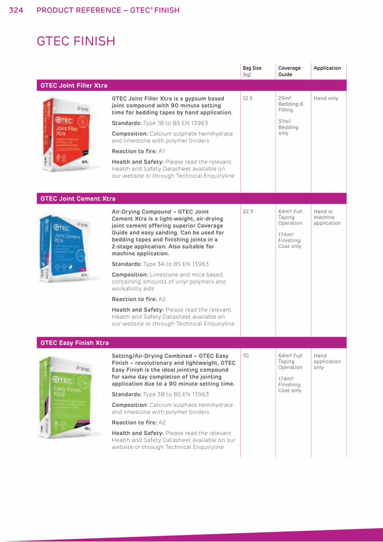
324
Bag Size
(kg)
Coverage
Guide
Application
GTEC Joint Filler Xtra
GTEC Joint Filler Xtra is a gypsum based joint compound with 90 minute setting time for bedding tapes by hand application.
Standards: Type 1B to BS EN 13963
Composition: Calcium sulphate hemihydrate
and limestone with polymer binders
Reaction to fire: A1
Health and Safety: Please read the relevant
Health and Safety Datasheet available on
our website or through Technical Enquiryline
12.5 25m² Bedding & Filling
37m² Bedding only
Hand only
GTEC Joint Cement Xtra
Air-Drying Compound – GTEC Joint Cement Xtra is a light-weight, air-drying joint cement offering superior Coverage Guide and easy sanding. Can be used for bedding tapes and finishing joints in a 2-stage application. Also suitable for machine application.
Standards: Type 3A to BS EN 13963
Composition: Limestone and mica based,
containing amounts of vinyl polymers and
workability aids
Reaction to fire: A2
Health and Safety: Please read the relevant
Health and Safety Datasheet available on
our website or through Technical Enquiryline
22.5 64m² Full Taping Operation
174m² Finishing Coat only
Hand or machine application
GTEC Easy Finish Xtra
Setting/Air-Drying Combined – GTEC Easy Finish – revolutionary and lightweight, GTEC Easy Finish is the ideal jointing compound for same day completion of the jointing application due to a 90 minute setting time.
Standards: Type 3B to BS EN 13963
Composition: Calcium sulphate hemihydrate
and limestone with polymer binders
Reaction to fire: A2
Health and Safety: Please read the relevant
Health and Safety Datasheet available on our
website or through Technical Enquiryline
10 64m² Full Taping Operation
174m² Finishing Coat only
Hand application only
GTEC FINISH
PRODUCT REFERENCE – GTEC® FINISH
325
ENQUIRYLINE T: 01275 377789 E: [email protected] www.siniat.co.uk
PRODUCT REFERENCE – GTEC® FINISH
Size
(kg)
Coverage
Guide
Application
GTEC Smartmix Xtra
Air-Drying Compound Ready Mixed – GTEC Smartmix Xtra is a light-weight compound offering superior coverage and easy sanding. Can be used for bedding tapes and finishing joints in a 2-stage application. Ideal for machine application.
Standards: Type 3A to BS EN 13963
Composition: Limestone and mica based,
containing amounts of vinyl polymers and
workability aids. Water based.
Reaction to fire: A2
Health and Safety: Please read the
relevant Health and Safety Datasheet
available on our website or through
Technical Enquiryline
20 50m2 Full Taping Operation
135m2
Finishing Coat Only
Hand or machine application
GTEC Aquamix
GTEC Aquamix is a water resistant ready-mixed joint cement. For use in humid and wet applications
Standards: Type 3A to BS EN 13963
Reaction to fire: A2
Health and Safety: Please read the
relevant Health and Safety Datasheet
available on our website or through
Technical Enquiryline
5
20
50m² Full Taping Operation
135m² Finishing Coat Only
(20kg)
Hand application only
GTEC Deco Filler
Deco Setting Compound – GTEC Deco Filler is a gypsum based compound designed for bedding and filling joints by hand when using the GTEC Deco System.
Standards: Type 1B to BS EN 13963
Composition: Calcium sulphate
hemihydrate and limestone with
polymer binders
Reaction to fire: A2
Health and Safety: Please read the
relevant Health and Safety Datasheet
available on our website or through
Technical Enquiryline
12.5 25m² Bedding & Filling only
Hand application only
326
Size
(kg)
Coverage
Guide
Application
GTEC Deco Joint Cement
Deco Air-Drying Compounds Ready Mixed – GTEC Deco Joint Cement is a light-weight, readymixed compound which must be used for the final coat of the jointing process and can be used for bedding and filling when using the GTEC Deco System.
Standards: Type 3A to BS EN 13963
Composition: Limestone and mica based,
containing amounts of vinyl polymers and
workability aids. Water based.
Reaction to fire: A2
Health and Safety: Please read the
relevant Health and Safety Datasheet
available on our website or through
Technical Enquiryline
20 50m² Full Taping
135m² Finishing Coat only
Hand or machine application
GTEC Deco Machine
Deco Air-Drying Compounds Ready Mixed – GTEC Deco Machine is a light-weight, readymixed compound formulated for use with Premier International Taping Tools. As with GTEC Deco Joint Cement, GTEC Deco Machine must be used for the final coat of the jointing process when using the GTEC Deco System.
Standards: Type 3A to BS EN 13963
Composition: Limestone and mica based,
containing amounts of vinyl polymers and
workability aids. Water based.
Reaction to fire: A2
Health and Safety: Please read the
relevant Health and Safety Datasheet
available on our website or through
Technical Enquiryline
20 50m² Full Taping
135m² Finishing Coat only
Machine only
GTEC FINISH continued
PRODUCT REFERENCE – GTEC® FINISH
327
ENQUIRYLINE T: 01275 377789 E: [email protected] www.siniat.co.uk
PRODUCT REFERENCE – GTEC® FINISH
Roll Size
(m)
Nominal Width
(mm)
GTEC Joint Tape
White perforated cross fibre tape for reinforcing joints. Suitable for hand or mechanical application with GTEC Jointing Compounds.
Standards: BS EN 13963
Health and Safety: Please read
the relevant Health and Safety
Datasheet available on our
website or through Technical
Enquiryline
150 53
GTEC Patching Tape
Self adhesive fibreglass tape for patching plasterboard.
Health and Safety: Please read
the relevant Health and Safety
Datasheet available on our
website or through Technical
Enquiryline
90 52
GTEC Flex Tape
Cross fibre paper tape with heat bonded zinc coated steel strips for the protection of external corner angles.
Health and Safety: Please read
the relevant Health and Safety
Datasheet available on our
website or through Technical
Enquiryline
33 51
GTEC Aquastrip
This mesh strip is used in the GTEC Aqua System to protect exposed drylining perimeters for wet applications.
Health and Safety: Please read
the relevant Health and Safety
Datasheet available on our
website or through Technical
Enquiryline
50 100
328
GTEC FINISH continued
PRODUCT REFERENCE – GTEC® FINISH
Bucket Size
(kg)
Coverage
Guide
Application
GTEC Universal Sealer
For use on plasterboard prior to painting for improved whiteness and covering power. Does not provide a vapour control layer.
Composition: A blend of limestone and
silica fillers dispersed with polymers
Reaction to fire: A2
Health and Safety: Please read the
relevant Health and Safety Datasheet
available on our website or through
Technical Enquiryline
10 100m² One coat
Hand application only
GTEC Drywall Sealer
Ivory, pre-decoration coat for plasterboard. Can provide 15 MNs/g vapour check, with two coats.
Composition: Aqueous, modified adhesive
based on polyvinyl acetate
Reaction to fire: A2
Health and Safety: Please read the
relevant Health and Safety Datasheet
available on our website or through
Technical Enquiryline
10 100m² One coat
70m² Two coats
Hand application only
Length
(mm)
GTEC Corner 90º External
Tape-On Beads are a paper tape reinforced with galvanised metal for protection of external corners and board edges. Used for taping and jointing.
Health and Safety: Please read the relevant Health and
Safety Datasheet available on our website or through
Technical Enquiryline
2400
3000
GTEC Duo Bead
Galvanised steel angle bead with 3mm nose for drywall corner reinforcement.
Health and Safety: Always wear protective gloves and
eyewear when handling, cutting and fitting
2400
3000
GTEC Edging Bead
Galvanised steel bead gives a neat edge to plasterboard. Perforated to provide a key for jointing compound.
Health and Safety: Always wear protective gloves and
eyewear when handling, cutting and fitting
3000
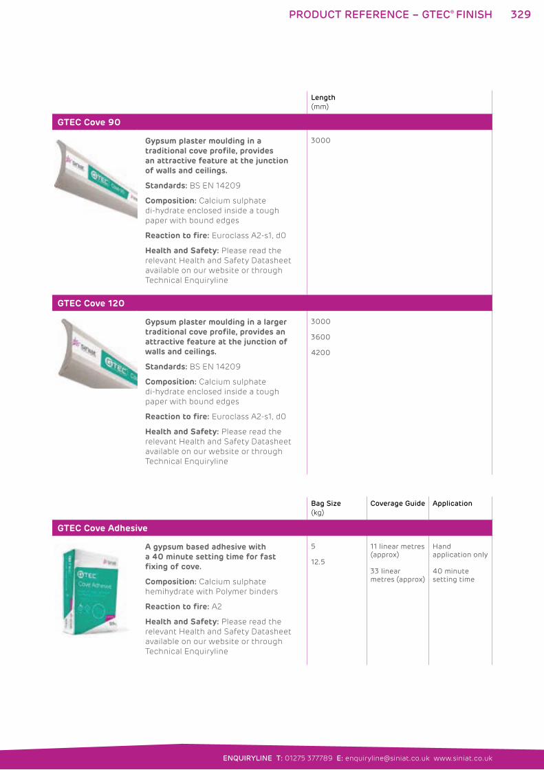
329
ENQUIRYLINE T: 01275 377789 E: [email protected] www.siniat.co.uk
PRODUCT REFERENCE – GTEC® FINISH
Length
(mm)
GTEC Cove 90
Gypsum plaster moulding in a traditional cove profile, provides an attractive feature at the junction of walls and ceilings.
Standards: BS EN 14209
Composition: Calcium sulphate
di-hydrate enclosed inside a tough
paper with bound edges
Reaction to fire: Euroclass A2-s1, d0
Health and Safety: Please read the
relevant Health and Safety Datasheet
available on our website or through
Technical Enquiryline
3000
GTEC Cove 120
Gypsum plaster moulding in a larger traditional cove profile, provides an attractive feature at the junction of walls and ceilings.
Standards: BS EN 14209
Composition: Calcium sulphate
di-hydrate enclosed inside a tough
paper with bound edges
Reaction to fire: Euroclass A2-s1, d0
Health and Safety: Please read the
relevant Health and Safety Datasheet
available on our website or through
Technical Enquiryline
3000
3600
4200
Bag Size
(kg)
Coverage Guide Application
GTEC Cove Adhesive
A gypsum based adhesive with a 40 minute setting time for fast fixing of cove.
Composition: Calcium sulphate
hemihydrate with Polymer binders
Reaction to fire: A2
Health and Safety: Please read the
relevant Health and Safety Datasheet
available on our website or through
Technical Enquiryline
5
12.5
11 linear metres (approx)
33 linear metres (approx)
Hand application only
40 minute setting time
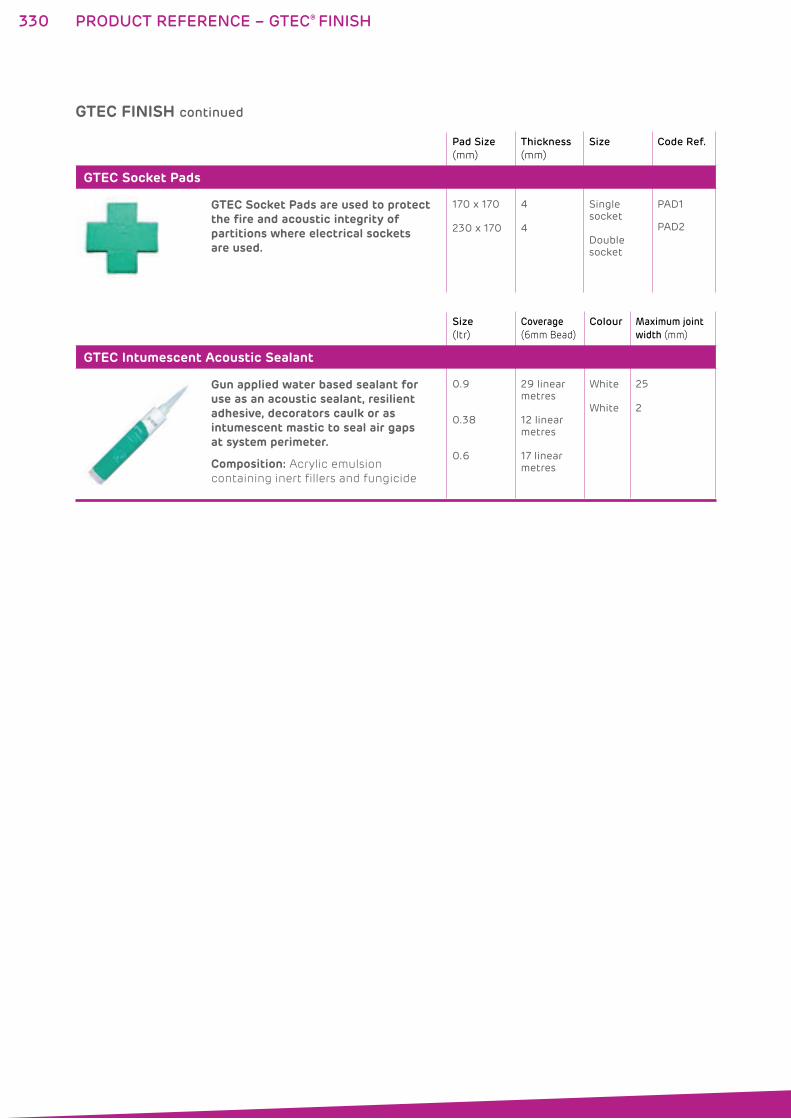
330
GTEC FINISH continued
PRODUCT REFERENCE – GTEC® FINISH
Size
(ltr)
Coverage
(6mm Bead)
Colour Maximum joint
width (mm)
GTEC Intumescent Acoustic Sealant
Gun applied water based sealant for use as an acoustic sealant, resilient adhesive, decorators caulk or as intumescent mastic to seal air gaps at system perimeter.
Composition: Acrylic emulsion
containing inert fillers and fungicide
0.9
0.38
0.6
29 linear metres
12 linear metres
17 linear metres
White
White
25
2
Pad Size
(mm)
Thickness
(mm)
Size Code Ref.
GTEC Socket Pads
GTEC Socket Pads are used to protect the fire and acoustic integrity of partitions where electrical sockets are used.
170 x 170
230 x 170
4
4
Single socket
Double socket
PAD1
PAD2
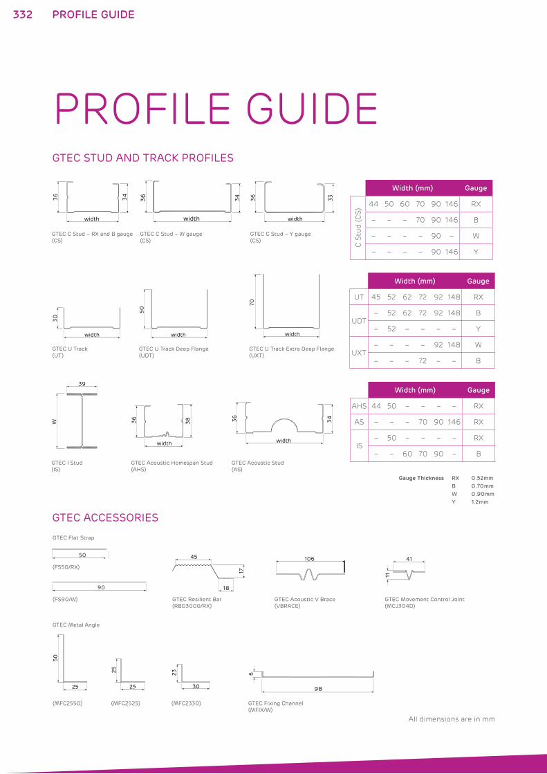
332 PROFILE GUIDE
GTEC STUD AND TRACK PROFILES
GTEC ACCESSORIES
PROFILE GUIDE
width
34
36
width
33
36
width
34
36
GTEC C Stud – RX and B gauge(CS)
GTEC C Stud – W gauge(CS)
GTEC C Stud – Y gauge(CS)
width
30
width
50
width
70
GTEC U Track(UT)
GTEC U Track Deep Flange(UDT)
GTEC U Track Extra Deep Flange(UXT)
W
39
GTEC I Stud(IS)
GTEC Acoustic Stud(AS)
GTEC Acoustic Homespan Stud(AHS)
width
36
38
width
34
36
98
6
GTEC Fixing Channel(MFIX/W)
18
17
45 106
GTEC Resilient Bar(RBD3000/RX)
GTEC Acoustic V Brace(VBRACE)
GTEC Movement Control Joint(MCJ304D)
(FS90/W)
(FS50/RX)
GTEC Flat Strap
50
90
(MFC2550) (MFC2525) (MFC2330)
23
30 25
25
25
50
41
11
GTEC Metal Angle
Width (mm) Gauge
C S
tud
(C
S)
44 50 60 70 90 146 RX
– – – 70 90 146 B
– – – – 90 – W
– – – – 90 146 Y
Width (mm) Gauge
UT 45 52 62 72 92 148 RX
UDT– 52 62 72 92 148 B
– 52 – – – – Y
UXT– – – – 92 148 W
– – – 72 – – B
Width (mm) Gauge
AHS 44 50 – – – – RX
AS – – – 70 90 146 RX
IS– 50 – – – – RX
– – 60 70 90 – B
Gauge Thickness RX 0.52mm
B 0.70mm
W 0.90mm
Y 1.2mm
All dimensions are in mm
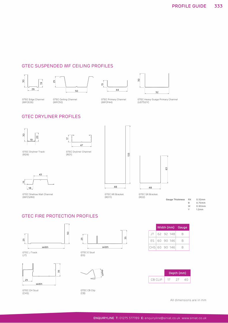
333
ENQUIRYLINE T: 01275 377789 E: [email protected] www.siniat.co.uk
PROFILE GUIDE
GTEC SUSPENDED MF CEILING PROFILES
52
30
GTEC Heavy Guage Primary Channel(UDT52/Y)
GTEC Ceiling Channel(MFC50)
GTEC Primary Channel(MFCP44)
GTEC Edge Channel (MFCE26)
25
50 26
19
30
44
15
GTEC DRYLINER PROFILES
GTEC Dryliner Track(RD9)
GTEC XR Bracket(RD11)
GTEC SR Bracket(RD2)
GTEC Dryliner Channel (RD1)
GTEC Shallow Wall Channel(MFCS/RX)
GTEC CR Bracket(RD7)
47
17
19
30
20
133
48
63
48
15
18
43
10
30
GTEC FIRE PROTECTION PROFILES
GTEC J Track(JT)
GTEC E Stud(ES)
GTEC CH Stud(CHS)
GTEC CB Clip(CB)
width
35
25
width
50
25
width
35
25
depth
Width (mm) Gauge
JT 62 92 148 B
ES 60 90 146 B
CHS 60 90 146 B
Depth (mm)
CB CLIP 17 27 40
Gauge Thickness RX 0.52mm
B 0.70mm
W 0.90mm
Y 1.2mm
All dimensions are in mm
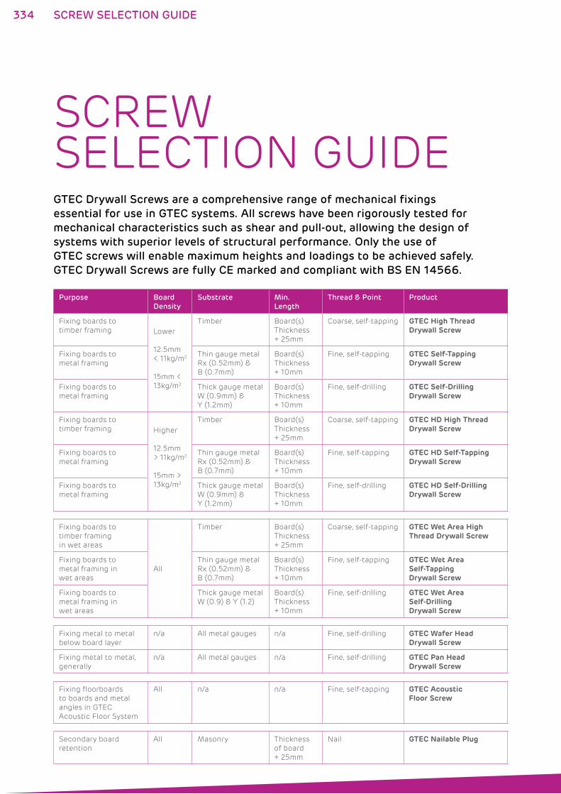
334
SCREW SELECTION GUIDEGTEC Drywall Screws are a comprehensive range of mechanical fixings
essential for use in GTEC systems. All screws have been rigorously tested for
mechanical characteristics such as shear and pull-out, allowing the design of
systems with superior levels of structural performance. Only the use of
GTEC screws will enable maximum heights and loadings to be achieved safely.
GTEC Drywall Screws are fully CE marked and compliant with BS EN 14566.
Purpose Board
Density
Substrate Min.
Length
Thread & Point Product
Fixing boards to
timber framing Lower
12.5mm
< 11kg/m2
15mm <
13kg/m2
Timber Board(s)
Thickness
+ 25mm
Coarse, self-tapping GTEC High Thread Drywall Screw
Fixing boards to
metal framing
Thin gauge metal
Rx (0.52mm) &
B (0.7mm)
Board(s)
Thickness
+ 10mm
Fine, self-tapping GTEC Self-Tapping Drywall Screw
Fixing boards to
metal framing
Thick gauge metal
W (0.9mm) &
Y (1.2mm)
Board(s)
Thickness
+ 10mm
Fine, self-drilling GTEC Self-Drilling Drywall Screw
Fixing boards to
timber framing Higher
12.5mm
> 11kg/m2
15mm >
13kg/m2
Timber Board(s)
Thickness
+ 25mm
Coarse, self-tapping GTEC HD High Thread Drywall Screw
Fixing boards to
metal framing
Thin gauge metal
Rx (0.52mm) &
B (0.7mm)
Board(s)
Thickness
+ 10mm
Fine, self-tapping GTEC HD Self-Tapping Drywall Screw
Fixing boards to
metal framing
Thick gauge metal
W (0.9mm) &
Y (1.2mm)
Board(s)
Thickness
+ 10mm
Fine, self-drilling GTEC HD Self-Drilling Drywall Screw
Fixing boards to
timber framing
in wet areas
All
Timber Board(s)
Thickness
+ 25mm
Coarse, self-tapping GTEC Wet Area High Thread Drywall Screw
Fixing boards to
metal framing in
wet areas
Thin gauge metal
Rx (0.52mm) &
B (0.7mm)
Board(s)
Thickness
+ 10mm
Fine, self-tapping GTEC Wet Area Self-Tapping Drywall Screw
Fixing boards to
metal framing in
wet areas
Thick gauge metal
W (0.9) & Y (1.2)
Board(s)
Thickness
+ 10mm
Fine, self-drilling GTEC Wet Area Self-Drilling Drywall Screw
Fixing metal to metal
below board layer
n/a All metal gauges n/a Fine, self-drilling GTEC Wafer Head Drywall Screw
Fixing metal to metal,
generally
n/a All metal gauges n/a Fine, self-drilling GTEC Pan Head Drywall Screw
Fixing floorboards
to boards and metal
angles in GTEC
Acoustic Floor System
All n/a n/a Fine, self-tapping GTEC Acoustic Floor Screw
Secondary board
retention
All Masonry Thickness
of board
+ 25mm
Nail GTEC Nailable Plug
SCREW SELECTION GUIDE
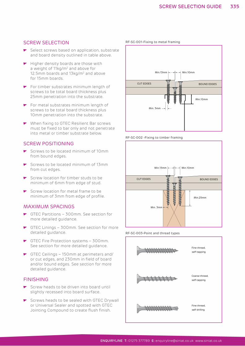
335
ENQUIRYLINE T: 01275 377789 E: [email protected] www.siniat.co.uk
SCREW SELECTION Select screws based on application, substrate
and board density outlined in table above.
Higher density boards are those with
a weight of 11kg/m2 and above for
12.5mm boards and 13kg/m2 and above
for 15mm boards.
For timber substrates minimum length of
screws to be total board thickness plus
25mm penetration into the substrate.
For metal substrates minimum length of
screws to be total board thickness plus
10mm penetration into the substrate.
When fixing to GTEC Resilient Bar screws
must be fixed to bar only and not penetrate
into metal or timber substrate below.
SCREW POSITIONING Screws to be located minimum of 10mm
from bound edges.
Screws to be located minimum of 13mm
from cut edges.
Screw location for timber studs to be
minimum of 6mm from edge of stud.
Screw location for metal frame to be
minimum of 3mm from edge of profile.
MAXIMUM SPACINGS GTEC Partitions – 300mm. See section for
more detailed guidance.
GTEC Linings – 300mm. See section for more
detailed guidance.
GTEC Fire Protection systems – 300mm.
See section for more detailed guidance.
GTEC Ceilings – 150mm at perimeters and/
or cut edges, and 230mm in field of board
and/or bound edges. See section for more
detailed guidance.
FINISHING Screw heads to be driven into board until
slightly recessed into board surface.
Screws heads to be sealed with GTEC Drywall
or Universal Sealer and spotted with GTEC
Jointing Compound to create flush finish.
Min.10mm
Min. 3mm
Min.10mmMin.13mm
CUT EDGES BOUND EDGES
Fine thread,
self-drilling
Coarse thread,
self-tapping
Fine thread,
self-tapping
RF-SC-001-Fixing to metal framing
RF-SC-003-Point and thread types
Min.25mm
Min. 3mm
Min.10mmMin.13mm
CUT EDGES BOUND EDGES
RF-SC-002 -Fixing to timber framing
SCREW SELECTION GUIDE
336
INTRODUCTIONSustainability has long been a core value at
Siniat and is now top of the agenda for everyone
in the construction supply chain. We remain
committed to sustainable development and
construction in both our business approach and
in meeting the needs of the built environment.
As a leading supplier of construction
products, Siniat has a huge responsibility.
Building materials meet basic human
needs for the buildings that are part of
everyday life. With economic growth and
social development increasing demand
we have to balance the human benefits
of our products with the availability of
finite and non-renewable resources.
Therefore, at Siniat, we focus on environmental
sustainability and leaving the lightest possible
trace on the earth while enabling the social and
economic sustainability of our operations.
SUSTAINABILITYSINIAT AND SUSTAINABILITY�� Plasterboard is fully recyclable – with no loss in quality
���GTEC Products and Systems are BRE Green Guide A and A+ rated and help collect
sustainability code credits
�� Unique product innovations minimise the number of boards needed in a design
�� Certified and managed sustainability: Responsible Sourcing BES 6001,
ISO 9001 and ISO 14001
�� Full plasterboard site waste collection and recycling from GTEC Wasteline Direct
�� The leading recycler of post-consumer plasterboard waste per unit sales (2009-2011)
SINIAT FIRSTS: 2004: The first plasterboard
manufacturer in the UK to
achieve ISO 9001 and ISO
14001 certification for all
activities – these international standards provide
the framework for our conservation of natural
resources. They ensure continuous improvement
in quality and service, as well as emission
reductions and innovative solutions for ever
more sustainable buildings.
2011: The first plasterboard
manufacturer in the UK to
achieve BES6001 certification,
the industry sustainability
standard for the responsible sourcing of
construction products. This independent
assessment certifies environmental stewardship
and social and economic sustainability within
our operations and supply chain.
SUSTAINABILITY
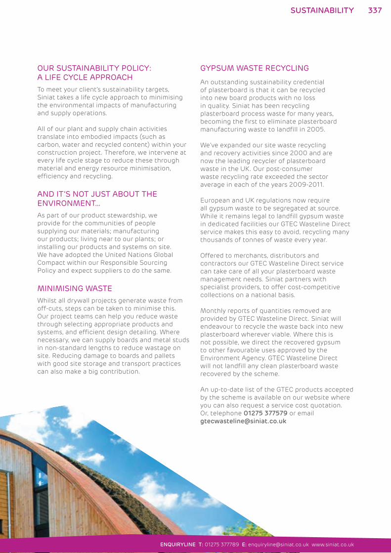
337
ENQUIRYLINE T: 01275 377789 E: [email protected] www.siniat.co.uk
OUR SUSTAINABILITY POLICY: A LIFE CYCLE APPROACHTo meet your client’s sustainability targets,
Siniat takes a life cycle approach to minimising
the environmental impacts of manufacturing
and supply operations.
All of our plant and supply chain activities
translate into embodied impacts (such as
carbon, water and recycled content) within your
construction project. Therefore, we intervene at
every life cycle stage to reduce these through
material and energy resource minimisation,
efficiency and recycling.
AND IT’S NOT JUST ABOUT THE ENVIRONMENT…As part of our product stewardship, we
provide for the communities of people
supplying our materials; manufacturing
our products; living near to our plants; or
installing our products and systems on site.
We have adopted the United Nations Global
Compact within our Responsible Sourcing
Policy and expect suppliers to do the same.
MINIMISING WASTEWhilst all drywall projects generate waste from
off-cuts, steps can be taken to minimise this.
Our project teams can help you reduce waste
through selecting appropriate products and
systems, and efficient design detailing. Where
necessary, we can supply boards and metal studs
in non-standard lengths to reduce wastage on
site. Reducing damage to boards and pallets
with good site storage and transport practices
can also make a big contribution.
GYPSUM WASTE RECYCLING
An outstanding sustainability credential
of plasterboard is that it can be recycled
into new board products with no loss
in quality. Siniat has been recycling
plasterboard process waste for many years,
becoming the first to eliminate plasterboard
manufacturing waste to landfill in 2005.
We’ve expanded our site waste recycling
and recovery activities since 2000 and are
now the leading recycler of plasterboard
waste in the UK. Our post-consumer
waste recycling rate exceeded the sector
average in each of the years 2009-2011.
European and UK regulations now require
all gypsum waste to be segregated at source.
While it remains legal to landfill gypsum waste
in dedicated facilities our GTEC Wasteline Direct
service makes this easy to avoid, recycling many
thousands of tonnes of waste every year.
Offered to merchants, distributors and
contractors our GTEC Wasteline Direct service
can take care of all your plasterboard waste
management needs. Siniat partners with
specialist providers, to offer cost-competitive
collections on a national basis.
Monthly reports of quantities removed are
provided by GTEC Wasteline Direct. Siniat will
endeavour to recycle the waste back into new
plasterboard wherever viable. Where this is
not possible, we direct the recovered gypsum
to other favourable uses approved by the
Environment Agency. GTEC Wasteline Direct
will not landfill any clean plasterboard waste
recovered by the scheme.
An up-to-date list of the GTEC products accepted
by the scheme is available on our website where
you can also request a service cost quotation.
Or, telephone 01275 377579 or email
SUSTAINABILITY
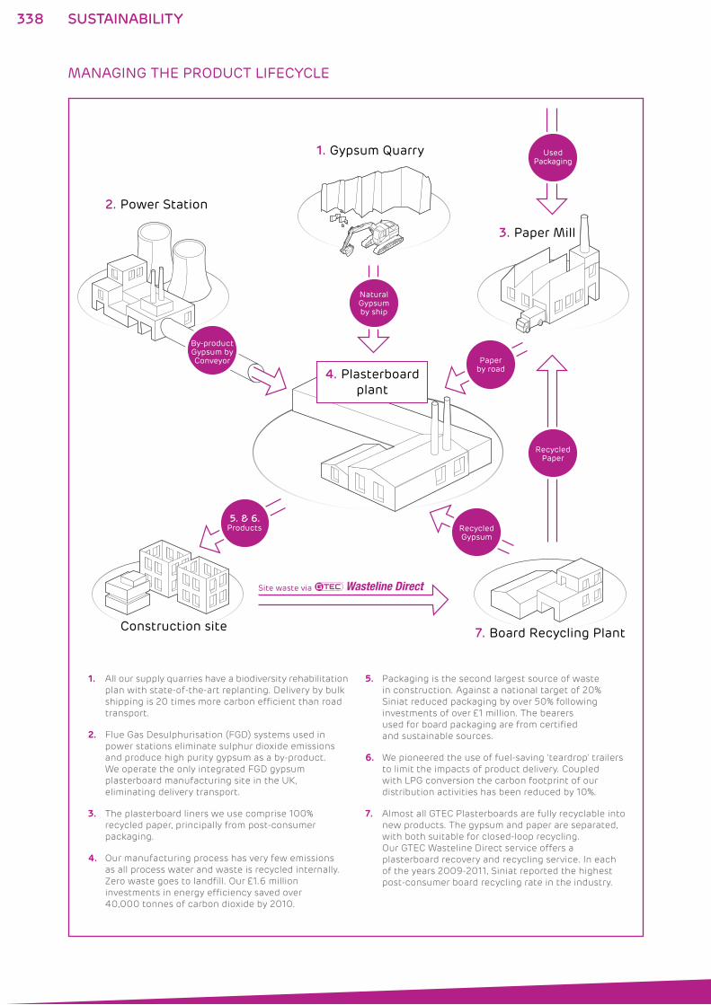
338
MANAGING THE PRODUCT LIFECYCLE
3. Paper Mill
2. Power Station
1. Gypsum Quarry
NaturalGypsumby ship
Paperby road
RecycledPaper
RecycledGypsum
UsedPackaging
7. Board Recycling Plant
Products5. & 6.
Construction site
Site waste via Wasteline Direct
By-productGypsum byConveyor
4. Plasterboardplant
SUSTAINABILITY
1. All our supply quarries have a biodiversity rehabilitation
plan with state-of-the-art replanting. Delivery by bulk
shipping is 20 times more carbon efficient than road
transport.
2. Flue Gas Desulphurisation (FGD) systems used in
power stations eliminate sulphur dioxide emissions
and produce high purity gypsum as a by-product.
We operate the only integrated FGD gypsum
plasterboard manufacturing site in the UK,
eliminating delivery transport.
3. The plasterboard liners we use comprise 100%
recycled paper, principally from post-consumer
packaging.
4. Our manufacturing process has very few emissions
as all process water and waste is recycled internally.
Zero waste goes to landfill. Our £1.6 million
investments in energy efficiency saved over
40,000 tonnes of carbon dioxide by 2010.
5. Packaging is the second largest source of waste
in construction. Against a national target of 20%
Siniat reduced packaging by over 50% following
investments of over £1 million. The bearers
used for board packaging are from certified
and sustainable sources.
6. We pioneered the use of fuel-saving ‘teardrop’ trailers
to limit the impacts of product delivery. Coupled
with LPG conversion the carbon footprint of our
distribution activities has been reduced by 10%.
7. Almost all GTEC Plasterboards are fully recyclable into
new products. The gypsum and paper are separated,
with both suitable for closed-loop recycling.
Our GTEC Wasteline Direct service offers a
plasterboard recovery and recycling service. In each
of the years 2009-2011, Siniat reported the highest
post-consumer board recycling rate in the industry.
339
ENQUIRYLINE T: 01275 377789 E: [email protected] www.siniat.co.uk
SUSTAINABILITY
GTEC PRODUCTS AND SYSTEMS FOR SUSTAINABLE BUILDINGSAs well as meeting regulation standards,
our high performance products and systems
enhance the sustainability of your building
projects in many ways:
Thermal boards contribute to the
conservation of energy and CO2 emissions
Fire boards contribute to safety as well as
building durability
Acoustic boards provide sound insulation
and enhance the conditions required in
our buildings and homes
Impact boards meet the severe duty
ratings required in public areas, reducing
maintenance and promoting durability
Through constant innovation, the GTEC
range includes unique, specialist boards
with enhanced features and performance
to minimise the volume used on site.
GTEC Megadeco
This patented product is unique.
Its pre-sealed surface speeds up
installation by eliminating sealing
on site.
GTEC LaDura
GTEC LaDura offers similar resource
efficiency plus metal stud savings, due
to its high strength. Excellent durability
will reduce the need for maintenance.
GTEC Aqua Board
The unique range of boards for wet
areas and external applications offers
major carbon reductions compared to
the cementitious boards traditionally
used. Excellent stability provides superior
air-tightness of the building envelope.
RESPONSIBLE SOURCING AND BES6001
Siniat was the first manufacturer in the UK
to offer plasterboard products certified to
the BRE Environmental and Sustainability
Framework Standard for the Responsible
Sourcing of Construction Products,
BES6001. Our review in 2012 extended
our rating to the ‘Very Good’ grading.
This certificate may be downloaded
from BRE’s Green Book Live website:
www.greenbooklive.com. When using
GTEC products on your projects, you can
collect credits within the Materials section
of the Code for Sustainable Homes or BREEAM.
BRE GREEN GUIDE
Due to the low environmental impact of
plasterboard products, the BRE Green Guide
rating for most of the GTEC systems listed
in the manual is A or A+. Embodied carbon
figures for building elements are also listed.
Our projects team will seek to provide the
highest possible rating in line with your
project’s specific performance requirements.
SUSTAINABLE CONSTRUCTION
340 SUSTAINABILITY
GTEC SYSTEMS IN THE CODE FOR SUSTAINABLE HOMES AND BREEAM:
The range of high performance GTEC Thermal Boards provide for space-efficient insulation.
The Global Warming Potential (GWP) of all these insulated boards is below 5, accessing additional credits.
GTEC systems achieve the high sound insulation values necessary to gain the credits for exceeding Building
Regulation requirements.
In the Materials Section, the excellent BRE Green Guide ratings of GTEC Systems and our BES6001 certification for
Responsible Sourcing both access credits.
Our plasterboard waste recovery service, GTEC Wasteline Direct, can support your site waste management needs
and is also eligible for credits.
Durability credits are available where Severe Duty partitions are used in corridors and public areas. (BREEAM only).
The zero release of VOC’s (volatile organic compounds) from GTEC boards contributes to Indoor Air Quality.
Specification of GTEC Megadeco can also minimise the release of VOC’s during the build. (BREEAM only).
Siniat supports contractors during construction in areas relevant to Project Management credits,
e.g. by minimising construction site impacts. Drawing on their vast experience with all building types,
our projects team will support achievement of the best possible BREEAM or Code rating.
THE CODE FOR SUSTAINABLE HOMES
The Code for Sustainable Homes applies in
England and Wales to drive a step-change
in sustainable home building practice.
GTEC Products, Systems and Services help gain
credits, pushing projects up the rating scale.
The Code measures the sustainability of the
home in nine design categories, and awards
a rating of one to six stars, depending on
achievement against the Code benchmarks.
For all Code levels, there are minimum
requirements for Energy and CO2 emissions
and Water consumption.
Credits are awarded in each of the design
areas, and the overall score is calculated from
a weighted scorecard of the section credits.
The assignment of credits within the Code’s
Energy section has been recently updated
to reflect the importance of installing a
thermally efficient building fabric as the
most cost-effective approach. This hierarchy,
known as the ‘fabric first’ approach, is
now reflected in the Code with credits for
Fabric Energy Efficiency performance.
BUILDING RESEARCH ESTABLISHMENT ENVIRONMENTAL ASSESSMENT METHOD (BREEAM)BREEAM is the most widely used environmental
assessment method for buildings in the UK. It
provides a consistent and robust means of rating
building sustainability. As with the Code for
Sustainable Homes, the GTEC range can make
a significant contribution to higher ratings.
BREEAM involves nine key areas of project
design. Credits are awarded in each of the
design areas and the overall score is calculated
from a weighted scorecard of the section
credits. The final score is then rated as Pass,
Good, Very Good, Excellent or Outstanding.
Education and Healthcare buildings must
meet certain minimum ratings, and other
ratings criteria may apply to building projects
as a condition of planning approval.
REFURBISHMENT PROJECTSFollowing much regulation in the new build
sector, the UK Low Carbon Construction
Action Plan is now focusing on improving the
thermal performance of existing buildings.
The Government is due to launch its Green
Deal package in Autumn 2012 where building
improvements will be funded by energy savings
in consumer energy bills. Siniat offers several
products and systems suitable for Green Deal
measures: please contact Technical Enquiryline
for further details.
Alongside the Green Deal, BRE have launched
a new BREEAM scheme in 2012 for the
sustainability assessment of domestic
refurbishment projects. Building on our
experience gained piloting the scheme,
Siniat will be pleased to support you with
any project requirements.

341
ENQUIRYLINE T: 01275 377789 E: [email protected] www.siniat.co.uk
HEALTH AND SAFETY
HEALTH AND SAFETYSiniat has a deep commitment to zero harm in our industrial activity. We follow an active policy for continuous improvement in reducing incidents and protecting our employees’ health. In our supply chain we require similar exacting standards from our suppliers.
To protect the health of construction workers and building occupants, we minimise the use of any hazardous materials and will avoid using substances of high concern. Our development programme brings innovative products to market which reduce health and safety risks on site and throughout the life of the building.
CE MARKINGAll Siniat GTEC products are CE marked in accordance with
the EU Construction Products Directive and the relevant
harmonised European standard. This ensures that the
essential requirements relevant to safety in use (e.g. reaction
to fire or tensile strength) are type tested in accredited
laboratories. Our ISO9001 quality management processes
ensure continuing compliance. From July 2013, products
will be CE Marked with reference to the EU Construction
Products Regulation 2011/305/EC.
MANUAL HANDLINGIn collaboration with the Health & Safety Executive, Siniat
has introduced weight labelling on all UK-produced board
products. This information helps users to reduce injuries
through risk assessment.
Example of product marking:
A range of mechanical handling aids for plasterboard
lifting and positioning is commercially available to reduce
the risk of injury. Please contact Technical Enquiryline for
further information.
CHEMICAL SUBSTANCES AND PRODUCT SAFETYSiniat ensures that all materials in its supply chain are
registered under REACH* where necessary. We have also
registered directly as a producer of calcium sulphate, the
main raw material used in our products; evidence and our
REACH registration number is available on request.
Siniat board products do not contain or emit volatile organic
compounds (VOCs) and our pre-finished GTEC Megadeco
Board removes the need for on-site sealing, further enhancing
the indoor air quality of your projects.
The sealing products in the Siniat GTEC range have an
aqueous base and contain VOCs at the lowest classification
level under the current regulations (<30g/litre).
All GTEC products are classified as non-hazardous according
to the CHIP4 (UK) and CLP (EU) Regulations and are stable
and non-reactive with other building materials.
The sawing of plasterboard and the sanding of finishing
compounds may generate dust. Whilst there are no known
toxicological effects for gypsum products, Occupational
Exposure Limits (OEL) exist for mineral dusts and the use
of personal protective equipment is recommended.
Safety Data Sheets are available for all GTEC products
covering handling, storage, use and disposal. Latest versions
may be downloaded from our website or obtained on request
from our Technical Enquiryline.
*European Regulation 2006/1907/EC on the Regulation, Evaluation,
Authorisation and Restriction of Chemicals.
HANDLESAFELY
25kg
342
STANDARDSGTEC PRODUCT STANDARDS AND TESTS
BS EN 520 Gypsum plasterboards. Definitions, Requirements
and Test Methods.
BS EN 14190 Gypsum plasterboard products from reprocessing.
Definitions, Requirements and Test Methods.
BS EN 13950 Gypsum plasterboard thermal/acoustic insulation composite
panels. Definitions, Requirements and Test Methods.
BS EN 15283 Gypsum boards with fibrous reinforcement – Definitions,
Requirements and Test Methods.
Part 1: Gypsum board with mat reinforcement
BS EN 14195 Metal framing components for gypsum plasterboard systems.
Definitions, Requirements and Test Methods.
BS EN 14566 Mechanical fasteners for gypsum plasterboard systems.
Definitions, Requirements and Test Methods.
BS EN 14353 Metal beads and feature profiles for use with gypsum
plasterboards. Definitions, Requirements and Test
Methods.
BS EN 14209 Preformed plasterboard cornices.
Definitions, Requirements and Test Methods.
BS EN 13963 Jointing materials for gypsum plasterboards.
Definitions, Requirements and Test Methods.
BS EN 14496 Gypsum based adhesives for thermal/acoustic insulation
composite panels and plasterboards. Definitions,
Requirements and Test Methods.
BS EN 13964 Suspended Ceilings – Requirements and Test Methods.
SYSTEMS / DESIGN / CODES OF PRACTICE
BS 8212 Code of practice for dry lining and – Partitioning using
gypsum plasterboard
BS 8000 Workmanship on building sites
Part 8: Code of practice for plasterboard – Partitions and
dry linings
BS EN 13914 Design, preparation and application of external rendering and
internal plastering
BS 5234 Specification for performance requirements for strength and
robustness
Part 1: – Partitions (including matching linings) – Code of
practice for design and installation
BS 5250 Code of Practice for the control of condensation in
buildings
BS 5385 Wall and floor tiling – Code of practice
Part 1: Design and installation of ceramic, natural stone and
mosaic wall tiling in normal conditions
Part 4: Design and installation of ceramic and mosaic tiling
in special conditions
BS EN ISO 6946 Building components and building elements.
Thermal resistance and thermal transmittance.
Calculation method.
BS 9999: 2008 Code of Practice for fire safety in the design, management
and use of buildings
STANDARDS
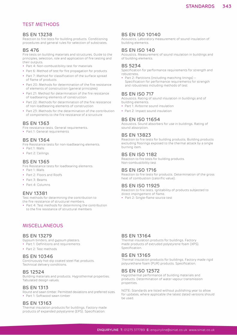
343
ENQUIRYLINE T: 01275 377789 E: [email protected] www.siniat.co.uk
TEST METHODS
BS EN 13238 Reaction to fire tests for building products. Conditioning
procedures and general rules for selection of substrates.
BS 476 Fire tests on building materials and structures. Guide to the
principles, selection, role and application of fire testing and
their outputs.
Part 4: Non-combustibility test for materials
Part 6: Method of test for fire propagation for products
Part 7: Method for classification of the surface spread
of flame of products
Part 20: Methods for determination of the fire resistance
of elements of construction (general principles)
Part 21: Method for determination of the fire resistance
of loadbearing elements of construction
Part 22: Methods for determination of the fire resistance
of non-loadbearing elements of construction
Part 23: Methods for the determination of the contribution
of components to the fire resistance of a structure
BS EN 1363 Fire resistance tests. General requirements.
Part 1: General requirements
BS EN 1364 Fire Resistance tests for non-loadbearing elements.
Part 1: Walls
Part 2: Ceilings
BS EN 1365 Fire Resistance tests for loadbearing elements.
Part 1: Walls
Part 2: Floors and Roofs
Part 3: Beams
Part 4: Columns
ENV 13381 Test methods for determining the contribution to
the fire resistance of structural members.
Part 4: Test methods for determining the contribution
to the fire resistance of structural members
BS EN ISO 10140 Acoustics. Laboratory measurement of sound insulation of
building elements.
BS EN ISO 140Acoustics. Measurement of sound insulation in buildings and
of building elements.
BS 5234Specification for performance requirements for strength and
robustness.
Part 2: Partitions (including matching linings) –
Specification for performance requirements for strength
and robustness including methods of test
BS EN ISO 717Acoustics. Rating of sound insulation in buildings and of
building elements.
Part 1: Airborne sound insulation
Part 2: Impact sound insulation
BS EN ISO 11654Acoustics. Sound absorbers for use in buildings. Rating of
sound absorption.
BS EN 13823Reaction to fire tests for building products. Building products
excluding floorings exposed to the thermal attack by a single
burning item.
BS EN ISO 1182Reaction to fire tests for building products.
Non-combustibility test
BS EN ISO 1716 Reaction to fire tests for products. Determination of the gross
heat of combustion (calorific value).
BS EN ISO 11925 Reaction to fire tests. Ignitability of products subjected to
direct impingement of flame.
Part 2: Single-flame source test
MISCELLANEOUS
BS EN 13279 Gypsum binders, and gypsum plasters.
Part 1: Definitions and requirements
Part 2: Test methods
BS EN 10346 Continuously hot-dip coated steel flat products.
Technical delivery conditions.
BS 12524 Building materials and products. Hygrothermal properties.
Tabulated design values.
BS EN 1313 Round and sawn timber. Permitted deviations and preferred sizes.
Part 1: Softwood sawn timber
BS EN 13163 Thermal insulation products for buildings. Factory made
products of expanded polystyrene (EPS). Specification.
BS EN 13164 Thermal insulation products for buildings. Factory
made products of extruded polystyrene foam (XPS).
Specification.
BS EN 13165 Thermal insulation products for buildings. Factory made rigid
polyurethane foam (PUR) products. Specification.
BS EN ISO 12572 Hygrothermal performance of building materials and
products. Determination of water vapour transmission
properties.
NOTE: Standards are listed without publishing year to allow
for updates, where applicable the latest dated versions should
be used.
STANDARDS
344 INDEX
Aacoustic board see Acoustic Homespan
Board; dB Board; LaDura; Universal;
Megadeco
Acoustic Floor Clip 317Acoustic Floor Systems 137, 170–6Acoustic Homespan Board 300Acoustic Homespan C Studs 308Acoustic Homespan MR Board 301Acoustic Homespan Partition Systems
43, 80–6Acoustic Homespan Starter Studs 308Acoustic Homespan Stud 332acoustic mass barrier ceilings 147acoustic performance 17
Acoustic Floor Systems 137
Acoustic Homespan Partition
Systems 43
Aqua Board Partition Systems 26–7
Ceiling Systems to Timber Floors 126
dB Board Partition Systems 33–7
Dryliner Ceiling Systems to Concrete
Soffit 127
E Board Partition Systems 44
Engineered Joist Systems 122
Fire Board Partition Systems 38–40
Horizontal Shaftwall Systems 249
LaDura Partition Systems 22–5
Lining Systems To Framed External
Walls 187
Lining Systems To Upgrade Internal
Walls 182–3
Mass Barrier Ceilings 136
Megadeco Partition Systems 28–31
Pregybel Independent Lining Systems
190–1
Pregybel MF Ceiling Systems 131–2
Separating Floor Systems 128–30
Shaftwall Stairwell Systems 248
Shaftwall Systems 244–7
Standard Board Partition Systems 41–2
Structural Frame Partition Systems 45
Suspended MF Ceiling Systems to
Protect Structure 135
Suspended MF Ceiling Systems to
Timber Floors 133–4
Timber Partition Systems 47–9
Universal Board Partition Systems 32
Masonry Robust Detail Systems 46
acoustic sealant, Intumescent Acoustic
Sealant 330Acoustic Stud 309, 332Acoustic Stud Partition Systems 72–8acoustic T-junctions
Acoustic Homespan Partition
Systems 86
Acoustic Stud Partition Systems 78
C Stud Partition Systems 59
Resilient Bar Partition Systems 93
Timber Partition Systems 118
Twin Frame Partition Systems 103
Acoustic V Brace 316, 332Acoustic V Brace 90° 230, 316adhesive
Cove Adhesive 329
Wall Lining Adhesive 321
Aqua Board 13, 303Aqua Board Partition Systems 26–7Aquamix 325Aquastrip 327
BBase Board 295beading products 328beams
fire resistant encasement 252, 271–2,
274
head deflection 63
boarding details
Acoustic Floor Systems 174–6
Acoustic Homespan Partition
Systems 84
Acoustic Stud Partition Systems 76
C Stud Partition Systems 55–6
Contour Lining System 206
Direct Bond Lining Systems 198
Direct-to-Timber Ceiling Systems
166–7
Dryliner Ceiling Systems 158–9
Dryliner Lining Systems 221
Independent Wall Lining Systems 231
Pregybel Independent Lining Systems
239–40
Pregybel MF Ceiling Systems 152
Resilient Bar Partition Systems 91
Shaftwall Systems 258–60
Shallow Wall Lining Systems 212
Suspended MF Ceiling Systems 143
Timber Partition Systems 115–16
Twin Frame Partition Systems 100–1
boards 12–13, 294–307alternative configurations 14–15
Acoustic Homespan Board 300
Acoustic Homespan MR Board 301
Aqua Board 303
Base Board 295
Contour Board 295
dB Board 300
E Board 299
Fire Board 297
Fire Core Board 299
Fire MR Board 298
Fire V Board 298
LaDura 302
Megadeco 301
Moisture Board 297
Plank 294
Pregybel Boards 306–7
Render Board 303
Standard Board 294
Thermal Board 304
Thermal K Board 305
Thermal PIR Board 305
Thermal XP Board 304
Universal Board 302
Vapour Base Board 296
Vapour Board 296
bonding
Contour Lining System 205
Direct Bond Lining Systems 196–7
Shallow Wall Lining Systems 211–12
Tiling 287
Universal Bonding Compound 321
BRE Green Guide 339breaking loads, Board 294–307
BREEAM (Building Research
Establishment environmental
Assessment Method) 336British Standards 342–3
BS 476-21 122–37
BS 476-22 22–49, 135–6, 244–9
BS 5234-2 18, 22–49, 244–9
BS EN 1364-1 22–49, 244–8
BS EN 1364-2 135–6, 249
BS EN 1365-2 122–37
BS EN ISO 140 17
BS EN ISO 717 17
BS EN ISO 11654 131–2
INDEX

345
ENQUIRYLINE T: 01275 377789 E: [email protected] www.siniat.co.uk
INDEX
Building Regulations
acoustic performance 17
compliance with Approved Document
E 299
fire performance 16
thermal performance 11
Building Research Establishment
environmental Assessment Method
(BREEAM) 336Building Research Establishment Green
Guide 339bulkhead
Dryliner Ceiling Systems 160
Pregybel MF Ceiling Systems 153
Suspended MF Ceiling Systems 145
CC Stud Partition Systems 50–71C Studs 308, 332cable tray penetrations
C Stud Partition Systems 65
Twin Frame Partition Systems 106
CB Clip 316, 333CE marking 341Ceiling Channel 311, 333ceiling channel splicing 141ceiling height change
Dryliner Ceiling Systems 160
Pregybel MF Ceiling Systems 153
Suspended MF Ceiling Systems 145
ceiling systems
Ceiling Systems to Timber Floors 126
Direct-to-Timber Ceiling Systems
162–8
Dryliner Ceiling Systems 154–61
Dryliner Ceiling Systems to Concrete
Soffit 127
Mass Barrier Ceilings 136
Pregybel MF Ceiling Systems 131–2,
148–53
Separating Floor Systems 128–30
Suspended MF Ceiling Systems
138–47
Suspended MF Ceiling Systems to
Protect Structure 135
Suspended MF Ceiling Systems to
Timber Floors 133–4
Ceiling Systems to Timber Floors 126ceramic tiling 285–7CH Stud 314, 333Code for Sustainable Homes 340codes of practice 342Collated Drywall Screws 323columns, fire resistant encasement
253, 263, 271, 273composition
Board 294–307
Drywall Screws 322–3
Finish 324–30
Fix 321
Frame 308–20
conductivity, Board 19, 294–307Connecting Clip 312Contour Board 295Contour Lining Systems 202–6Corner 90º External 328Corner and Edge beads 328corner details
Acoustic Homespan Partition
Systems 86
Acoustic Stud Partition Systems 78
C Stud Partition Systems 58, 59
Direct Bond Lining Systems 200
Dryliner Lining Systems 223
Encasement Systems 273
Independent Wall Lining Systems 233
Pregybel Independent Lining Systems
240
Resilient Bar Partition Systems 93
Shaftwall Systems 262
Shallow Wall Lining Systems 214
Timber Partition Systems 118
Twin Frame Partition Systems 103
corners, taping and jointing 282, 328Cove 288–90, 329Cove Adhesive 329curved partitions
C Stud Partition Systems 70–1
Contour Board 295
Contour Lining Systems 202–6
Twin Frame Partition Systems 108–9
DdB Board 300dB Board Partition Systems 33–7Deco Filler 325Deco Joint Cement 326Deco Machine 326decoration 283deflection heads see head deflection
design codes 342design pull-out loads see pull-out loads
dimensionally stability 19dimensions (see also maximum height;
thickness)
Board 294–307
Frame 308–20
Direct Bond Lining Systems 192–201Direct-to-Timber Ceiling Systems
162–8domestic buildings see residential
projects
door frames/jambs
Acoustic Homespan Partition
Systems 85
Acoustic Stud Partition Systems 77
C Stud Partition Systems 57–8
Direct Bond Lining Systems 199
Resilient Bar Partition Systems 92
Shallow Wall Lining Systems 213
Timber Partition Systems 117
Twin Frame Partition Systems 102
Dryliner Ceiling Systems 154–61Dryliner Ceiling Systems to Concrete
Soffit 127Dryliner Channel 312, 333Dryliner Channel Connector 314Dryliner Lining Systems 216–24Dryliner Profiles 333Dryliner Track 313, 333Drywall Screws 322–3, 334–5Drywall Sealer 328duct penetrations, Shaftwall Systems
264–5duct protection systems 266Duo Bead 328duty rating see strength duty
346 INDEX
EE Board 299E Board Partition Systems 44E Stud 315, 333Easy Finish Xtra 324E-coat 321Edge Channel 311, 333Edging Bead 328educational projects 9electrical services see cable tray
penetrations
Encasement Fire Protection Systems
250–3, 268–75Engineered Joist Systems 122environmental issues 336–9external insulation 184–7
Ffinishing 278–90
Board 294–307
Taping and Jointing Systems 278–83
Tiling 287
skim plastering 284
finishing products 324–30Aquamix 325
Aquastrip 327
Corner 90º External 328
Cove 90 329
Cove 120 329
Cove Adhesive 329
Deco Filler 325
Deco Joint Cement 326
Deco Machine 326
Drywall Screw heads 335
Drywall Sealer 328
Duo Bead 328
Easy Finish Xtra 324
Edging Bead 328
Flex Tape 327
Intumescent Acoustic Sealant 330
Joint Cement Xtra 324
Joint Filler Xtra 324
Joint Tape 327
Patching Tape 327
Smartmix Xtra 325
Socket Pads 330
Universal Sealer 328
Fire Board 297Fire Board Partition Systems 38–40Fire Core Board 299Fire MR Board 298fire performance 16
Acoustic Floor Systems 137
Acoustic Homespan Partition
Systems 43
Aqua Board Partition Systems 26–7
Board 294–307
Ceiling Systems to Timber Floors 126
dB Board Partition Systems 33–7
Dryliner Ceiling Systems to Concrete
Soffit 127
E Board Partition Systems 44
Engineered Joist Systems 122
Finish 324–30
Fire Board Partition Systems 38–40
Fix 321
Frame 308–20
Horizontal Shaftwall Systems 249
LaDura Partition Systems 22–5
Lining Systems To Framed External
Walls 187
Lining Systems To New External Walls
180–1
Lining Systems To Upgrade Internal
Walls 182–3
Mass Barrier Ceilings 136
Megadeco Partition Systems 28–31
Roof Lining Systems 188–9
Separating Floor Systems 128–30
Shaftwall Stairwell Systems 248
Shaftwall Systems 244–7
Standard Board Partition Systems
41–2
Structural Frame Partition Systems
45
Suspended MF Ceiling Systems to
Protect Structure 135
Suspended MF Ceiling Systems to
Timber Floors 133–4
Timber Partition Systems 47–9
Universal Board Partition Systems 32
Masonry Robust Detail Systems 46
Fire Protection profiles 333
fire protection systems 244–75Encasement Fire Protection Systems
250–3
Encasement Systems 268–75
Horizontal Shaftwall Systems 249
Shaftwall Stairwell Systems 248
Shaftwall Systems 244–7, 254–67
Fire V Board 298Fixing Channel 319, 332fixing details see boarding details
fixing options 69fixing products
bonding and adhesives 321
Drywall Screws 322–3
fixtures
C Stud Partition Systems 67–8
Suspended MF Ceiling Systems 146
Flat Strap 319, 332Flex Tape 327Flex Track Deep Flange 310floor systems 121
Acoustic Floor Systems 137, 170–6
Engineered Joist Systems 122
Plank 294
Separating Floor Systems 128–30
four way junctions
C Stud Partition Systems 59
Twin Frame Partition Systems 103
frame components 308–20Acoustic Floor Clip 317
Acoustic Homespan C Studs 308
Acoustic Homespan Starter Studs
308
Acoustic Stud 309
Acoustic V Brace 316
Acoustic V Brace 90º 316
C Studs 308
CB Clip 316
Ceiling Channel 311
CH Stud 314
Connecting Clip 312
Dryliner Channel 312
Dryliner Channel Connector 314
Dryliner Track 313
E Stud 315
Edge Channel 311
Fixing Channel 319
Flat Strap 319
Flex Track Deep Flange 310
INDEX
347
ENQUIRYLINE T: 01275 377789 E: [email protected] www.siniat.co.uk
INDEX
Heavy Gauge Primary Channel 311
I Stud 309
Insulation Hold 320
J Track 315
Metal Angle 90° 319
Movement Control Joint 320
Phonissimo Acoustic Hanger 317
Phonistar Acoustic Hanger 317
Primary Channel 311
Resilient Bar 315
Resilient Tape 318
Shallow Wall Channel 314
Soffit Cleat 312
SR Bracket 313
Staggered Stud Clip 318
Strap Hanger 318
U Track 309
U Track Deep Flange 310
U Track Extra Deep Flange 310
XR Bracket 313
frame details
Acoustic Floor Systems 173
Acoustic Homespan Partition
Systems 83
Acoustic Stud Partition Systems 75
C Stud Partition Systems 53–4
Direct-to-Timber Ceiling Systems 165
Dryliner Ceiling Systems 157
Dryliner Lining Systems 220–1
Encasement Systems 271–2
Independent Wall Lining Systems 230
Pregybel MF Ceiling Systems 151
Resilient Bar Partition Systems 91
Shaftwall Systems 258–9
Shallow Wall Lining Systems 211–12
Suspended MF Ceiling Systems 141–2
Timber Partition Systems 113–14
Twin Frame Partition Systems 97–9
GGTEC 3GTEC Lifetime System Warranty 3gypsum waste recycling 337–8
Hhead deflection
C Stud Partition Systems 61–2
Twin Frame Partition Systems 105–6
health and safety 341healthcare projects 7Heavy Gauge Primary Channel 311, 333height see ceiling height change;
maximum height
homogenous systems 15horizontal joint reinforcement
Acoustic Homespan Partition
Systems 84
Acoustic Stud Partition Systems 76
C Stud Partition Systems 55
Resilient Bar Partition Systems 92
Twin Frame Partition Systems 100
Horizontal Shaftwall Systems 249horizontal shaftwall systems 267hospitals see healthcare projects
hybrid systems 14
II Stud 309, 332impact sound insulation
Acoustic Floor Systems 137
Ceiling Systems to Timber Floors 126
Dryliner Ceiling Systems to Concrete
Soffit 127
Engineered Joist Systems 122
Mass Barrier Ceilings 136
Separating Floor Systems 128–30
Suspended MF Ceiling Systems to
Protect Structure 135
Suspended MF Ceiling Systems to
Timber Floors 133–4
Independent Wall Lining Systems
226–34insulation
acoustic/sound 17
fire 16
thermal 19
Acoustic Homespan Partition
Systems 83
C Stud Partition Systems 54
Dryliner Lining Systems 221
Timber Partition Systems 115
Twin Frame Partition Systems 100
insulation board see Thermal
Insulation Hold 320Intumescent Acoustic Sealant 330
JJ Track 315, 333Joint Cement Xtra 324joint compounds 324–6Joint Filler Xtra 324joint reinforcement see horizontal joint
reinforcement
Joint Tape 327jointing systems see taping and jointing
systems
junction details
Acoustic Floor Systems 175
Acoustic Homespan Partition
Systems 86
Acoustic Stud Partition Systems 78
C Stud Partition Systems 58–60
Direct Bond Lining Systems 200
Direct-to-Timber Ceiling Systems 167
Dryliner Ceiling Systems 160
Dryliner Lining Systems 223
Encasement Systems 273
Independent Wall Lining Systems 233
Resilient Bar Partition Systems 93
Shaftwall Systems 262–3
Shallow Wall Lining Systems 213
Suspended MF Ceiling Systems 145
Timber Partition Systems 118
Twin Frame Partition Systems 103–4
348 INDEX
LLaDura Partition Systems 22–5LaDura Board 12, 302LaDura pattress 67–8, 69Lafarge Plasterboard see Siniat
lengths
Board 294–307
Frame 308–20
life cycle approach 337light steel framing systems (SFS) see
SFS junctions
lining depth change 224lining systems 179–241
Contour Lining Systems 202–6
Direct Bond Lining Systems 192–201
Dryliner Lining Systems 216–24
Independent Wall Lining Systems
226–34
Lining Systems To Framed External
Walls 187
Lining Systems To New External Walls
180
Lining Systems To Thermally Upgrade
External Walls 184–6
Lining Systems To Upgrade Internal
Walls 182–3
Pregybel Independent Lining Systems
190–1, 236–41
Roof Lining Systems 188–9
Shallow Wall Lining Systems 208–15
Mmanual handling 341Masonry Robust Detail Systems 46masonry substrates 196, 211masonry wall junctions
C Stud Partition Systems 59–60
Encasement Systems 274
Resilient Bar Partition Systems 93
Twin Frame Partition Systems 104
Mass Barrier Ceilings 136mass to height/span ratio 18maximum height 18
Acoustic Homespan Partition
Systems 43
Aqua Board Partition Systems 26–7
dB Board Partition Systems 33–7
E Board Partition Systems 44
Fire Board Partition Systems 38–40
Horizontal Shaftwall Systems 249
LaDura Partition Systems 22–5
Lining Systems To Framed External
Walls 187
Lining Systems To Upgrade Internal
Walls 183
Megadeco Partition Systems 28–31
Pregybel Independent Lining Systems
190–1
Shaftwall Stairwell Systems 248
Shaftwall Systems 244–7
Standard Board Partition Systems
41–2
Structural Frame Partition Systems
45
Timber Partition Systems 47–9
Universal Board Partition Systems 32
Masonry Robust Detail Systems 46
Megadeco 13, 301Megadeco Partition Systems 28–31Metal Angle 90° 319, 332metal bead 328minimum thickness
Acoustic Floor Systems 137
Ceiling Systems to Timber Floors 126
Dryliner Ceiling Systems to Concrete
Soffit 127
Engineered Joist Systems 122
Lining Systems To Framed External
Walls 187
Lining Systems To New External Walls
180–1
Lining Systems To Thermally Upgrade
External Walls 184–6
Lining Systems To Upgrade Internal
Walls 182–3
Pregybel MF Ceiling Systems 131–2
Separating Floor Systems 128–30
Suspended MF Ceiling Systems to
Timber Floors 133–4
mixed board systems 15Moisture Board 297moisture resistant board see Aqua;
LaDura; Moisture
Movement Control Joint 320, 332movement control joints
C Stud Partition Systems 56
Contour Lining System 206
Direct Bond Lining Systems 198
Dryliner Ceiling Systems 159
Dryliner Lining Systems 222
Independent Wall Lining Systems 232
Shaftwall Systems 260
Shallow Wall Lining Systems 213
Suspended MF Ceiling Systems 144
Twin Frame Partition Systems 101
NNailable Plug 323
Oopenings
Acoustic Homespan Partition
Systems 85
Acoustic Stud Partition Systems 77
C Stud Partition Systems 57–8
Direct Bond Lining Systems 199
Dryliner Lining Systems 222
Independent Wall Lining Systems 232
Resilient Bar Partition Systems 92
Shaftwall Systems 261
Shallow Wall Lining Systems 213
Suspended MF Ceiling Systems 144
Timber Partition Systems 117
Twin Frame Partition Systems 102
over-height boarding
C Stud Partition Systems 56
Dryliner Lining Systems 221
Independent Wall Lining Systems 231
Timber Partition Systems 115–16, 117
Twin Frame Partition Systems 101
Ppartition systems 21–119
Acoustic Homespan Partition
Systems 43, 80–6
Acoustic Stud Partition Systems 72–8
Aqua Board Partition Systems 26–7
C Stud Partition Systems 50–71
dB Board Partition Systems 33–7
E Board Partition Systems 44
Fire Board Partition Systems 38–40
LaDura Partition Systems 22–5
Megadeco Partition Systems 28–31
Resilient Bar Partition Systems 88–93
Standard Board Partition Systems 41–2
Structural Frame Partition Systems 45
Timber Partition Systems 47–9,
110–19
Twin Frame Partition Systems 94–108
Universal Board Partition Systems 32
Masonry Robust Detail Systems 46
INDEX
349
ENQUIRYLINE T: 01275 377789 E: [email protected] www.siniat.co.uk
INDEX
parge coat see E Coat
Patching Tape 327penetrations
C Stud Partition Systems 65–6
Shaftwall Systems 264–5
Twin Frame Partition Systems 106
perforated board see Pregybel
performance tables see system
performance
Phonissimo Acoustic Hanger 317Phonistar Acoustic Hanger 317pipe penetrations
C Stud Partition Systems 65, 66
Twin Frame Partition Systems 106, 107
Plank 294Pregybel Acoustic Panel 241Pregybel Boards 306–7Pregybel Independent Lining Systems
190–1, 236–41Pregybel MF Ceiling Systems 131–2,
148–53Primary Channel 311, 333product life cycles 337product safety 341profile guide 332–3pull-out loads 69
purlins, head deflection, C Stud
Partition Systems 62–3, 64
Rrecycling of waste 337–8refurbishment projects (sustainability)
340render, E-coat 321Render Board 303renovating walls, Contour Lining
Systems 202–6residential projects 11Resilient Bar 315, 332Resilient Bar Partition Systems 88–93Resilient Tape 318Responsible Sourcing of Construction
Products (BES6001) 339Robust Details 46, 129-30Roof Lining Systems 188–9
Ssafe handing 341school buildings see educational
projects
screws
Drywall Screws 322–3
selection guide 334–5
sealant
Intumescent Acoustic Sealant 330
sealer
Drywall Sealer 328
Universal Sealer 328
Separating Floor Systems 128–30service openings see penetrations
SFS junctions 104Shaftwall Stairwell Systems 248Shaftwall Systems 244–7, 254–67Shallow Wall Channel 314, 333Shallow Wall Lining Systems 208–15Siniat 2skim plastering 284Smartmix Xtra 325socket pad fittings
C Stud Partition Systems 65
Twin Frame Partition Systems 106
Socket Pads 330Soffit Cleat 312sound absorption see acoustic
performance
sound insulation see acoustic
performance
splayed corners
C Stud Partition Systems 59
Twin Frame Partition Systems 103
SR Bracket 313, 333Staggered Stud Clip 318stairwell systems, Shaftwall Systems
265Standard Board 294Standard Board Partition Systems 41–2standards 342–3 (see also British
Standards)
Board 294–307
Drywall Screws 322–3
Finish 324–30
Fix 321
Frame 308–20
steelwork
fire resistant encasement 250–3,
271–5
Fire Core Board 299
SFS junctions 104
shaftwall junction 263
Strap Hanger 318strength duty 18
Acoustic Homespan Partition
Systems 43
Aqua Board Partition Systems 26–7
dB Board Partition Systems 33–7
E Board Partition Systems 44
Fire Board Partition Systems 38–40
Horizontal Shaftwall Systems 249
LaDura Partition Systems 22–5
Megadeco Partition Systems 28–31
Shaftwall Stairwell Systems 248
Shaftwall Systems 244–7
Standard Board Partition Systems 41–2
Structural Frame Partition Systems 45
Timber Partition Systems 47–9
Universal Board Partition Systems 32
Masonry Robust Detail Systems 46
Structural Frame Partition Systems 45structural performance 18Stud and Track profiles 332stud splices
Acoustic Stud Partition Systems 75
C Stud Partition Systems 53
Twin Frame Partition Systems 99
Shaftwall Systems 258
substrates (see also masonry
substrates)
Contour Lining System 205
Direct Bond Lining Systems 196
Dryliner Lining Systems 219
Shallow Wall Lining Systems 211
Taping and Jointing Systems 281
Suspended Ceiling profiles 333Suspended MF Ceiling Systems 138–47Suspended MF Ceiling Systems to
Protect Structure 135Suspended MF Ceiling Systems to
Timber Floors 133–4sustainability issues 2, 11, 336–40symmetrical systems 14system performance 16–19
Floor and Ceiling Systems 122–37
Lining Systems 180–91
Partition Systems 22–49
Shaftwall Systems 244–53

350
Ttape on bead 328taping and jointing systems 278–83,
324–7telescopic deflection head assembly
63–4test methods 343Thermal Board 304Thermal K Board 305thermal performance 19, 294–307Thermal PIR Board 305Thermal XP Board 304thickness (see also minimum thickness)
Board 294–307
Frame 308–20
Partition Systems 22–49
Shaftwall Systems 244–9
tiling
Contour Lining Systems 202–6
Tiling 285–7
Timber Partition Systems 47–9, 110–19T-junctions
C Stud Partition Systems 58–60
Shaftwall Systems 262
Timber Partition Systems 118
Twin Frame Partition Systems 103–4
Twin Frame Partition Systems 94–108
UU Track 309, 332U Track Deep Flange 310, 332U Track Extra Deep Flange 310, 332universal beams see beams
Universal Board 302Universal Board Partition Systems 32Universal Bonding Compound 321universal columns see columns
Universal Sealer 328U-values 19
Lining Systems To Framed External
Walls 187
Lining Systems To New External Walls
180–1
Lining Systems To Thermally Upgrade
External Walls 184–6
Lining Systems To Upgrade Internal
Walls 183
Roof Lining Systems 188–9
VVapour Base Board 296Vapour Board 296V-brace fixing 99
WWall Lining Adhesive 321wall linings see linings
waste recycling 337–8Wasteline Direct 337–8website, Siniat 5weight
Board 294–307
Floor and Ceiling Systems 122–37
Partition Systems 22–49
Shaftwall Systems 244–9
weighted sound reduction index (Rw) 17wet areas (see also Aqua)
tiling 285–7
widths
Board 294–307
Frame 308–20
window reveals
Direct Bond Lining Systems 199
Dryliner Lining Systems 222
Independent Wall Lining Systems 232
Shallow Wall Lining Systems 213
XXR Bracket 313, 333
INDEX
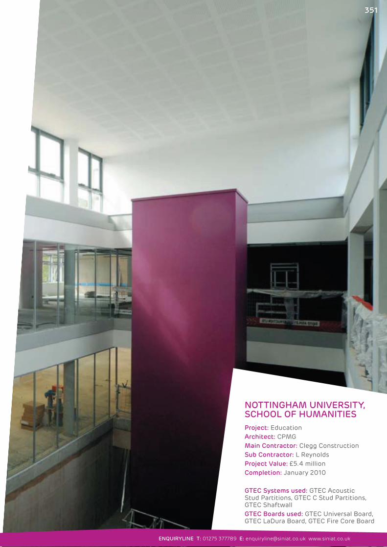
NOTTINGHAM UNIVERSITY, SCHOOL OF HUMANITIES
Project: EducationArchitect: CPMGMain Contractor: Clegg ConstructionSub Contractor: L ReynoldsProject Value: £5.4 millionCompletion: January 2010
GTEC Systems used: GTEC Acoustic Stud Partitions, GTEC C Stud Partitions, GTEC ShaftwallGTEC Boards used: GTEC Universal Board, GTEC LaDura Board, GTEC Fire Core Board
ENQUIRYLINE T: 01275 377789 E: [email protected] www.siniat.co.uk
351

352
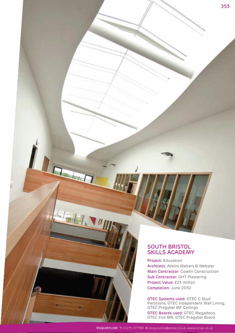
SOUTH BRISTOL SKILLS ACADEMY
Project: EducationArchitect: Atkins Walters & WebsterMain Contractor: Cowlin ConstructionSub Contractor: GHT PlasteringProject Value: £23 millionCompletion: June 2010
GTEC Systems used: GTEC C Stud Partitions, GTEC Independent Wall Lining, GTEC Pregybel MF CeilingsGTEC Boards used: GTEC Megadeco, GTEC Fire MR, GTEC Pregybel Board
353
ENQUIRYLINE T: 01275 377789 E: [email protected] www.siniat.co.uk
SINIAT LIMITEDMarsh Lane, Easton-in-Gordano Bristol BS20 0NF
T +44 (0)1275 377773 www.siniat.co.uk
© 2012 Siniat Limited GB_CC_01_0912
GB ORDERLINEFor placing orders, delivery enquiries and local stockists etc.
T 0800 373636
F 01275 377700
LITERATURELINEFor Siniat literature.
T 01275 377582
THE TRAINING CENTREFor all drywall training needs from basic introduction
to advanced skills and development.
T 01275 377581
F 01275 377402
IRELAND ORDERLINEFor placing orders, delivery enquiries and local stockists etc.
T +353 (0)1 6203114
F +353 (0)1 6203117
TECHNICAL ENQUIRYLINETechnical advice and project enquiries.
T 01275 377789
F 01275 377456
GTEC® WASTELINE DIRECTPlasterboard waste management enquiries.
T 01275 377579
F 01275 774950
Cover image: Barnsley College: see page 8.