Embed Size (px)
Citation preview

� �ISO dialects
___________________
___________________
___________________
___________________
___________________
___________________
___________________
___________________
___________________
SINUMERIK
SINUMERIK 840D sl / 828D ISO dialects
Function Manual
Valid for Control SINUMERIK 840D sl / 840DE sl SINUMERIK 828D Software Version CNC software 4.5
02/2012 6FC5397-7BP40-3BA0
Short description 1
Programming 2
Tool changes and tool offsets
3
Cycles and contour definition 4
Commissioning 5
Supplementary conditions 6
Data descriptions (MD, SD) 7
Data fields, lists 8
Alarms 9

Siemens AG Industry Sector Postfach 48 48 90026 NÜRNBERG GERMANY
Order number: 6FC5397-7BP40-3BA0 Ⓟ 10/2012 Technical data subject to change
Copyright © Siemens AG 1999 - 2012.All rights reserved
Legal information Warning notice system
This manual contains notices you have to observe in order to ensure your personal safety, as well as to prevent damage to property. The notices referring to your personal safety are highlighted in the manual by a safety alert symbol, notices referring only to property damage have no safety alert symbol. These notices shown below are graded according to the degree of danger.
DANGER indicates that death or severe personal injury will result if proper precautions are not taken.
WARNING indicates that death or severe personal injury may result if proper precautions are not taken.
CAUTION indicates that minor personal injury can result if proper precautions are not taken.
NOTICE indicates that property damage can result if proper precautions are not taken.
If more than one degree of danger is present, the warning notice representing the highest degree of danger will be used. A notice warning of injury to persons with a safety alert symbol may also include a warning relating to property damage.
Qualified Personnel The product/system described in this documentation may be operated only by personnel qualified for the specific task in accordance with the relevant documentation, in particular its warning notices and safety instructions. Qualified personnel are those who, based on their training and experience, are capable of identifying risks and avoiding potential hazards when working with these products/systems.
Proper use of Siemens products Note the following:
WARNING Siemens products may only be used for the applications described in the catalog and in the relevant technical documentation. If products and components from other manufacturers are used, these must be recommended or approved by Siemens. Proper transport, storage, installation, assembly, commissioning, operation and maintenance are required to ensure that the products operate safely and without any problems. The permissible ambient conditions must be complied with. The information in the relevant documentation must be observed.
Trademarks All names identified by ® are registered trademarks of Siemens AG. The remaining trademarks in this publication may be trademarks whose use by third parties for their own purposes could violate the rights of the owner.
Disclaimer of Liability We have reviewed the contents of this publication to ensure consistency with the hardware and software described. Since variance cannot be precluded entirely, we cannot guarantee full consistency. However, the information in this publication is reviewed regularly and any necessary corrections are included in subsequent editions.

ISO dialects Function Manual, 02/2012, 6FC5397-7BP40-3BA0 3
Table of contents
1 Short description........................................................................................................................................ 7
2 Programming ............................................................................................................................................. 9
2.1 Function activation .........................................................................................................................9 2.1.1 Switching between the operating modes .....................................................................................11
2.2 G commands................................................................................................................................13 2.2.1 Display of the G code...................................................................................................................18 2.2.2 Display of non-modal G codes.....................................................................................................19 2.2.3 G code output to PLC ..................................................................................................................20 2.2.4 Decoupling the frames between Siemens and ISO mode...........................................................22 2.2.5 Writing work offset with G10 ........................................................................................................26 2.2.6 Programming the decimal point ...................................................................................................27 2.2.7 Rapid lifting with G10.6 ................................................................................................................30 2.2.8 Multiple-start threads with G33 ....................................................................................................31 2.2.9 Thread with variable lead G34 (ISO dialect T).............................................................................32 2.2.10 Dwell time in spindle revolutions G04..........................................................................................32 2.2.11 Scaling (G50, G51) and mirroring G50.1, G51.1 (ISO dialect M) ................................................33 2.2.12 G60 directed positioning ..............................................................................................................36 2.2.13 2D/3D rotation G68/G69 (ISO dialect M) .....................................................................................37 2.2.14 Double slide or double turret processing G68/G69......................................................................39 2.2.15 Polar coordinates G15/G16 (ISO dialect M) ................................................................................43 2.2.16 Interpolation of polar coordinates G12.1/G13.1 (G112/G113).....................................................44 2.2.17 Cylindrical interpolation G07.1 (G107).........................................................................................46 2.2.18 Interrupt program with M96/M97 (ASUB) ....................................................................................49 2.2.19 Comments....................................................................................................................................52 2.2.20 Skip block.....................................................................................................................................52 2.2.21 Auxiliary function output...............................................................................................................53 2.2.22 Approach 1st home position with intermediate point (G28).........................................................54 2.2.23 Switching precontrol on/off with G08 P........................................................................................54 2.2.24 Compressor in ISO dialect mode.................................................................................................55 2.2.25 Automatic corner override G62....................................................................................................56
2.3 Substitution by a substitution cycle with a tool selection block....................................................58 2.3.1 Milling ...........................................................................................................................................58 2.3.2 Turning .........................................................................................................................................61 2.3.3 Indirect programming in ISO mode using $ variables..................................................................63
2.4 Subprogram and macro technology.............................................................................................64 2.4.1 Subprogram technique: M98........................................................................................................64 2.4.2 Siemens language commands in ISO dialect mode....................................................................67 2.4.3 Expansion of subprogram call for contour preparation with CONTPRON...................................68 2.4.4 Macro commands with G65, G66 and G67 .................................................................................71 2.4.5 Changing mode during macro calls with G65/G66 ......................................................................74 2.4.6 Macro call via M function .............................................................................................................75 2.4.7 Macro call via G function..............................................................................................................76 2.4.8 High-speed cycle cutting G05 P...................................................................................................79 2.4.9 Switchover modes for DryRun and skip planes ...........................................................................80

Table of contents
ISO dialects 4 Function Manual, 02/2012, 6FC5397-7BP40-3BA0
2.4.10 Eight-digit program number......................................................................................................... 81 2.4.11 System variable for level stack in ISO mode .............................................................................. 82
3 Tool changes and tool offsets .................................................................................................................. 85 3.1 Shared tool offset memory .......................................................................................................... 85 3.1.1 Tool offsets: T, D (ISO dialect M)................................................................................................ 85 3.1.2 Possible H numbers .................................................................................................................... 86 3.1.3 Tool offset T (ISO dialect T) ........................................................................................................ 89 3.1.4 Tool change cycle ....................................................................................................................... 93
4 Cycles and contour definition................................................................................................................... 95 4.1 Sequence of cycle calls in the external CNC system using G commands ................................. 95 4.2 Global user data (GUD) .............................................................................................................. 98 4.3 Drilling cycles (ISO dialect M) ................................................................................................... 100 4.3.1 Overview and parameter description ........................................................................................ 100 4.3.2 Description of shell cycle CYCLE381M .................................................................................... 102 4.3.3 Description of shell cycle CYCLE383M .................................................................................... 103 4.3.4 Description of shell cycle CYCLE384M .................................................................................... 104 4.3.5 Description of shell cycle CYCLE387M .................................................................................... 105 4.4 Turning and drilling cycles (ISO dialect T) ................................................................................ 106 4.4.1 Turning cycles G70 to G76 ....................................................................................................... 106 4.4.2 Turning cycles G77 to G79 ....................................................................................................... 111 4.4.3 Drilling cycles G80 to G89......................................................................................................... 113 4.4.4 Description of shell cycle CYCLE383T ..................................................................................... 116 4.4.5 Description of shell cycle CYCLE384T ..................................................................................... 117 4.4.6 Description of shell cycle CYCLE385T ..................................................................................... 118 4.5 System variables....................................................................................................................... 119 4.6 Programming contour definitions (ISO dialect T) ...................................................................... 122 4.6.1 End point programming with angles.......................................................................................... 123 4.6.2 Straight line with angle .............................................................................................................. 124 4.6.3 Two straight lines ...................................................................................................................... 126 4.6.4 Three straight lines.................................................................................................................... 128 4.6.5 Multi-edge turning with G51.2 ................................................................................................... 130 4.6.6 Contour repetition G72.1/G72.2................................................................................................ 131 4.6.7 Output on an external device / an external file.......................................................................... 134 4.6.8 Convex thread with G35 and G36............................................................................................. 136
5 Commissioning ...................................................................................................................................... 137 5.1 Machine data............................................................................................................................. 137 5.1.1 Active G command for PLC....................................................................................................... 143 5.1.2 Tool change, tool data............................................................................................................... 143 5.1.3 G00 always with exact stop....................................................................................................... 144 5.1.4 Response to syntax faults ......................................................................................................... 144 5.1.5 Selection of code system A, B, C (ISO dialect T) ..................................................................... 145 5.1.6 Fixed feedrates F0 - F9............................................................................................................. 146 5.1.7 Parallel axes G17 (G18/G19)<Axis name>............................................................................... 148 5.1.8 Inserting chamfers and radii...................................................................................................... 148 5.1.9 Rotary axis function................................................................................................................... 149 5.1.10 Program coordination between 2 channels and M commands................................................. 151 5.2 Standard machine data assignment for ISO dialect ................................................................. 152

Table of contents
ISO dialects Function Manual, 02/2012, 6FC5397-7BP40-3BA0 5
6 Supplementary conditions ..................................................................................................................... 155
6.1 Supplementary conditions..........................................................................................................155
6.2 Constraints .................................................................................................................................156 6.2.1 Program commands...................................................................................................................157 6.2.2 Tool management ......................................................................................................................159 6.2.3 Control response with power on, reset and block search..........................................................160
7 Data descriptions (MD, SD) ................................................................................................................... 161
7.1 General NC machine data .........................................................................................................161
7.2 Channel-specific machine data..................................................................................................178
7.3 Axis-specific machine data ........................................................................................................196
7.4 Channel-specific setting data.....................................................................................................198
7.5 Axis-specific setting data ...........................................................................................................203
7.6 Channel-specific cycle machine data ........................................................................................204
7.7 Channel-specific cycle setting data ...........................................................................................206
8 Data fields, lists ..................................................................................................................................... 209
8.1 Machine data..............................................................................................................................209
8.2 Setting data ................................................................................................................................212
9 Alarms ................................................................................................................................................... 213
Index...................................................................................................................................................... 217

Table of contents
ISO dialects 6 Function Manual, 02/2012, 6FC5397-7BP40-3BA0

ISO dialects Function Manual, 02/2012, 6FC5397-7BP40-3BA0 7
Short description 1
Introduction Part programs from external CNC systems can be read in and executed.
This brochure describes the commissioning required for this and how NC programs from an external CNC system are processed. Functional differences are also explained.
Note
You will find a detailed description of the external program functions in the original documentation provided for the external CNC system.
Terms used The following terms are defined for this brochure:
● ISO dialect M is similar to the G code of the "Fanuc16-Milling" control system
● ISO dialect T is similar to the G code of the "Fanuc16-Turning" system B control system
● ISO dialect original corresponds to the original Fanuc16 control system

Short description
ISO dialects 8 Function Manual, 02/2012, 6FC5397-7BP40-3BA0

ISO dialects Function Manual, 02/2012, 6FC5397-7BP40-3BA0 9
Programming 22.1 Function activation
Switchover The 18800 $MN_EXTERN_LANGUAGE machine data is used to activate the external language. The ISO dialect M or T language types can be selected via 10880 $MN_EXTERN_CNC_SYSTEM machine data.
The external language can be activated separately for each channel. For example, channel 1 can run in ISO mode while channel 2 is active in Siemens mode.
The two G commands from group 47 are used to switch from Siemens mode to ISO dialect mode:
● G290: Siemens NC programming language active
● G291: ISO dialect NC programming language active
The active tool, tool offsets and work offsets are retained.
G290 and G291 must be the only components of an NC program block.
Siemens mode The following conditions are valid in the Siemens mode:
● The default of the G commands can be defined for each channel via the 20150 $MC_GCODE_RESET_VALUE machine data.
● No language commands from the ISO dialects can be programmed in Siemens mode.

Programming 2.1 Function activation
ISO dialects 10 Function Manual, 02/2012, 6FC5397-7BP40-3BA0
ISO dialect mode The following conditions apply when ISO dialect mode is active:
● The ISO dialect mode can be set with machine data as the default setting for the control system. In ISO dialect mode, the control system then reboots by default.
● Only G commands from the ISO dialect can be programmed; the programming of Siemens G functions is not possible in ISO mode.
● ISO dialect and Siemens language cannot be mixed in the same NC block.
● G commands cannot be used to switch between ISO dialect M and ISO dialect T
● Subprograms that are programmed in Siemens mode can be called.
● If Siemens functions are to be used, a switchover to Siemens mode must first be made.
PowerOn/Reset The table below shows the possible combinations of MD10880 $MN_MM_EXTERN_CNC_SYSTEM and MD20150 $MC_GCODE_RESET_VALUE[46]. This defines the Power On/Reset behavior.
Table 2- 1 Function activation
After PowerOn/Reset $MC_GCODE_RESET_VALUES[46]= $MN_EXTERN_CNC_SYSTEM = Siemens mode active, switching to ISO dialect M possible
1 G290 Siemens mode 1 ISO dialect M
Siemens mode active, switching to ISO dialect T possible
1 G290 Siemens mode 2 ISO dialect T
ISO dialect M active, switching to Siemens mode possible
2 G291 ISO dialect mode 1 ISO dialect M
ISO dialect T active, switching to Siemens mode possible
2 G291 ISO dialect mode 2 ISO dialect T
Data storage Imported ISO programs are stored as main programs in the NC data storage under the default address:
_N_WKS_DIR/_N_SHOPMILL_WPD.
The input can be changed by editing the DINO.INI file in the USER folder. More information can be found in the following brochure:
References: SINUMERIK 840D sl / 828D

Programming 2.1 Function activation
ISO dialects Function Manual, 02/2012, 6FC5397-7BP40-3BA0 11
2.1.1 Switching between the operating modes
G290/291 The following G functions can be used to switch between the Siemens mode and the ISO dialect mode:
● G290 - Siemens NC programming language active
● G291 - ISO Dialect NC Programming language active
The active tool, tool compensation and work offsets are not influenced by the switchover.
G290 and G291 must be programmed alone in an NC block.
G65/66 Macro, non-modal and modal:
The programmed subprogram is called. A switch will only be made to Siemens mode if the PROC instruction is used in the first line of the subprogram.
If such a program ends with M17 or RET, a mode switch is made back to ISO mode during the return.
Siemens up call in ISO mode Modal and non-modal subprogram calls, e.g.
N100 CALL "SHAFT"
or
N100 MCALL SHAFT
or
N100 SHAFT

Programming 2.1 Function activation
ISO dialects 12 Function Manual, 02/2012, 6FC5397-7BP40-3BA0
Modal and non-modal subprogram calls with parameter transfer
N100 MCALL SHAFT ("ABC", 33.5)
or
N100 SHAFT ("ABC", 33.5)
Subprogram calls with path details
N100 CALL "/_N_SPF_DIR/SHAFT
or
N100 MCALL /_N_SPF_DIR/SHAFT
or
N100 PCALL /_N_SPF_DIR/SHAFT
During subprogram calls, Siemens mode is selected implicitly and a switch is made back to ISO dialect mode at the end of the subprogram.
Modal, non-modal cycles If a modal or non-modal cycle is programmed in ISO mode, a shell cycle is called.
A switch is made to Siemens mode during this call.

Programming 2.2 G commands
ISO dialects Function Manual, 02/2012, 6FC5397-7BP40-3BA0 13
2.2 G commands The G codes of ISO dialect T and M relate to the G code system B.
The active G codes of ISO mode can be read using system variable $P_EXTGG[...]. The numbers next to the G code specify the respective value in $P_EXTGG[...]. The 20154 EXTERN_GCODE_RESET_VALUES[n] 0, ..., 30 MD is used to define the G codes which are effective in the power up if the NC channel isn't in Siemens mode.
Table 2- 2 The default setting is marked as 1)
ISO dialect T ISO dialect M Description System A System C Group 1 G00 1) 1 G00 1) 1 Rapid traverse G0 G0 G01 2 G01 2 Linear motion G01 G01 G02 3 G02 3 Circle/helix in clockwise direction G02 G02 G02.2 6 Involute in clockwise direction G03 4 G03 4 Circle/helix in counter-clockwise direction G03 G03 G03.2 7 Involute in counter-clockwise direction G33 5 G33 5 Thread cutting with constant lead G32 G33 G34 9 Thread cutting with variable lead G34 G34 G35 Convex thread in the clockwise direction G35 G35 G36 Convex thread in the counter-clockwise direction G36 G36 G77 6 Longitudinal turning cycle G90 G20 G78 7 Thread cutting cycle G92 G21 G79 8 Face turning cycle G94 G24 Group 2 G17 1) 1 XY plane G18 2 ZX plane G19 3 YZ plane G96 1 Constant cutting rate on G96 G96 G97 1) 2 Constant cutting rate off G97 G97 Group 3 G90 1) 1 Absolute programming not G90 G91 2 Incremental programming not G91 Group 4 G22 1 Working area limitation, protection zone 3 on G23 1) 2 Working area limitation, protection zone 3 off G68 1 Double slide/turret on G68 G68 G69 1) 2 Double slide/turret off G69 G69 Group 5 G23 1) 2 Inverse-time feedrate (rpm) G94 1 G94 1) 1 Feedrate in [mm/min, inch/min] G98 G94 G95 1) 2 G95 2 Revolutional feedrate in [mm/rev, inch/rev] G99 G95

Programming 2.2 G commands
ISO dialects 14 Function Manual, 02/2012, 6FC5397-7BP40-3BA0
ISO dialect T ISO dialect M Description System A System C Group 6 G20 1) 1 G20 1) (G70) 1 Inch input system G20 G70 G21 2 G21 (G71) 2 Metric input system G21 G71 Group 7 G40 1) 1 G40 1) 1 Deselection of cutter radius compensation G40 G40 G41 2 G41 2 Compensation left of contour G41 G41 G42 3 G42 3 Offset to right of contour G42 G42 Group 8 G43 1 Positive tool length compensation on -- G43 G44 2 Negative tool length compensation on -- G44 G49 1) 3 Tool length compensation off -- G49 Group 9 G22 1 Working area limitation, protection zone 3 on G22 G22 G23 1) 2 Working area limitation, protection zone 3 off G23 G23 G73 1 Deep-hole drilling cycle with chip breakage G73 G73 G74 2 Left tapping cycle G74 G74 G76 3 Precision drilling cycle G76 G76 G80 1) 4 Cycle off G80 G80 G81 5 Drilling cycle counterboring G81 G81 G82 6 Countersink drilling cycle G82 G82 G83 7 Deep-hole drilling cycle with chip removal G83 G83 G84 8 Right tapping cycle G84 G84 G85 9 Drilling cycle G85 G85 G86 10 Drilling cycle, retraction with G00 G86 G86 G87 11 Reverse countersinking G87 G87 G89 13 Drilling cycle, retraction with machining feedrate G89 G89 Group 10 G80 1) 1 Drilling cycle off G80 G80 G83 2 Front face deep-hole drilling G83 G83 G84 3 Front face tapping G84 G84 G85 4 Front face drilling cycle G85 G85 G87 5 Side surface deep-hole drilling G87 G87 G88 6 Side surface tapping G88 G88 G89 7 Side surface drilling G89 G89 G98 1) 1 Return to starting point in fixed cycles -- G98 G99 2 Return to point R in fixed cycles -- G99 Group 11 G98 1) 1 Return to starting point in drilling cycles -- G98 G99 2 Return to point R in drilling cycles -- G99 G50 1) 1 Scaling off G50 G50 G51 2 Scaling on G51 G51

Programming 2.2 G commands
ISO dialects Function Manual, 02/2012, 6FC5397-7BP40-3BA0 15
ISO dialect T ISO dialect M Description System A System C Group 12 G66 1 G66 1 Macro module call G66 G66 G67 1) 2 G67 1) 2 Delete macro module call G67 G67 Group 13 G96 1 Constant cutting rate on G96 G96 G97 1) 2 Constant cutting rate off G97 G97 Group 14 G54 1) 1 G54 1) 1 Select work offset G54 G54 G55 2 G55 2 Select work offset G55 G55 G56 3 G56 3 Select work offset G56 G56 G57 4 G57 4 Select work offset G57 G57 G58 5 G58 5 Select work offset G58 G58 G59 6 G59 6 Select work offset G59 G59 G54 P{1...48} 1 G54 P{1...48} 1 Extended work offsets G54.1 7 G54.1 7 Extended work offsets G54.1 G54.1 G54 P0 1 G54 P0 1 "External work offset" Group 15 G61 1 Exact stop modal G61 G61 G62 4 Automatic corner override G62 G62 G63 2 Tapping mode G63 G63 G64 1) 3 Continuous-path mode G64 G64 Group 16 G17 1 XY plane G17 G17 G18 1) 2 ZX plane G18 G18 G19 3 YZ plane G19 G19 G68 1 Rotation ON 2D 3D G68 G68 G69 1) 2 Rotation OFF G69 G69 Group 17 G15 1) 1 Polar coordinates off G15 G15 G16 2 Polar coordinates on G16 G16 Group 18 (non-modal effective) G04 1 G04 1 Dwell time in [s] or spindle revolutions G04 G04 G05 20 G05 18 High-speed cycle cutting G05 G05 G05.1 22 G05.1 20 High-speed cycle -> Call CYCLE305 G05.1 G05.1 G07.1 18 G07.1 16 Cylindrical interpolation G07.1 G07.1 G08 12 Feedforward control ON/OFF G08 G08 G09 2 Exact stop G09 G09 G10 2 G10 3 Write work offset / tool offset G10 G10 G10.6 19 G10.6 17 Rapid lifting ON/OFF (T)
Retraction from contour (POLF) (M) G10.6 G10.6
G11 4 End parameter entry G11 G11 G27 16 G27 13 Referencing check (under development) G27 G27
Programming 2.2 G commands
ISO dialects 16 Function Manual, 02/2012, 6FC5397-7BP40-3BA0
ISO dialect T ISO dialect M Description System A System C G28 3 G28 5 Approach 1st reference point G28 G28 G30 4 G30 6 Apporach 2nd/3rd/4th reference point G30 G30 G30.1 21 G30.1 19 Reference point position G30.1 G30.1 G31 5 G31 7 Measuring with touch-trigger probe G31 G31 G52 6 G52 8 Programmable work offset G52 G52 G53 17 G53 9 Approach position in machine coordinate system G53 G53 G60 24 G60 22 Directed positioning G60 G60 G65 7 G65 10 Macro call G65 G65 G70 8 Finishing cycle G70 G72 G71 9 Stock removal cycle, longitudinal axis G71 G73 G72 10 Stock removal cycle, transverse axis G72 G74 G72.1 14 Contour repetition with rotation G72.1 G72.1 G72.2 15 Linear contour repetition G72.2 G72.2 G73 11 Contour repetition G73 G75 G74 12 Deep-hole boring and grooving in the longitudinal axis (Z) G74 G76 G75 13 Deep-hole boring and grooving in the transverse axis (X) G75 G77 G76 14 Multiple thread cutting cycle G76 G78 G92 15 G92 11 Set actual value, spindle speed limitation G50 G92 G92.1 23 G92.1 21 Delete actual value, reset the WCS G92.1 G92.1 Group 20 G50.2 1) 1 Multi-edge turning OFF G50.2 G50.2- G51.2 2 Multi-edge turning ON G51.2 -G51.2 Group 21 G13.1 1) 1 TRANSMIT OFF G13.1 G13.1 G12.1 2 TRANSMIT ON G12.1 G12.1 Group 22 G50.1 1 Mirroring on programmed axis OFF G50.1 G50.1 G51.1 2 Mirroring on programmed axis ON G51.1 G51.1 Group 25 G13.1 1 Polar coordinates interpolation OFF G13.1 G13.1 G12.1 2 Polar coordinates interpolation ON G12.1 G12.1 Group 31 G290 1) 1 G290 1) 1 Select Siemens mode G290 G290 G291 1 G291 1 Select ISO dialect mode G291 G291
Modally effective G commands Modally effective G commands which have an identical function in both systems (Siemens and ISO dialect) are treated as follows:

Programming 2.2 G commands
ISO dialects Function Manual, 02/2012, 6FC5397-7BP40-3BA0 17
When programming these G codes in one language, the corresponding G code for the other language is determined and activated. The following G codes are affected by this:
Table 2- 3 G codes have an identical function in Siemens mode and ISO dialect mode
G commands in Siemens mode Corresponding G commands ISO dialect T
Corresponding G commands ISO dialect M
Group 1: G00, G01, G02, G03, G33 Group 1: G00, G01, G02, G03, G33 Group 1: G00, G01, G02, G03, G33 Group 6: G17, G18, G19 Group 16: G17, G18, G19 Group 2: G17, G18, G19 Group 7: G40, G41, G42 Group 7: G40, G41, G42 Group 7: G40, G41, G42 Group 8: G54 to G554 Group 14: G54 to G59, G54 P1 to P48 Group 10: G60, G64 Group 18: G60, G64 Group 18: G60, G64 Group 13: G700, G710 Group 6: G20, G21 Group 6: G20, G21 Group 14: G90, G91 Group 3: G90, G91 Group 3: G90, G91 Group 15: G94 G95 G96 G961 G97 G971
Group 5: G94 Group 2: G97 Group 5: G95 Group 2: G97 Group 5: G95 Group 2: G96 Group 5: G94 Group 2: G96 Group 5: G95 Group 2: G97 Group 5: G94 Group 2: G97
Group 5: G94 Group 13: G97 Group 5: G95 Group 13: G97 Group 5: G95 Group 13: G96 Group 5: G94 Group 13: G96 Group 5: G95 Group 13: G97 Group 5: G94 Group 13: G97
Note
If individual G commands from the groups stated in the table cannot be depicted, the basic setting saved in MD20154 $MC_EXTERN_GCODE_RESET_VALUES and/or MD20152 $MC_GCODE_RESET_VALUES is activated.
Example: ISO mode
N5 G00 X100. Y100.
N10 G90 ;activates G90 in ISO mode group 3 ;in Siemens mode group 14
N15 G290 ;switches over to Siemens, G90 is active
N20 G91 ;activates G91 in ISO mode group 3 ;in Siemens mode group 14
N25 G291 ;switches over to ISO mode
N30 G291 ;G91 is active

Programming 2.2 G commands
ISO dialects 18 Function Manual, 02/2012, 6FC5397-7BP40-3BA0
2.2.1 Display of the G code The G code must always be displayed in the same language (Siemens or ISO Dialect) as the relevant current block. If the display of the blocks is suppressed with DISPLOF, the current G codes continue to be displayed in the same language as the active block.
Example The G functions of the ISO dialect mode are used to call the Siemens standard cycles. To do this, DISPLOF is programmed at the start of the relevant cycle; this way the G functions that are programmed in the ISO dialect language continue to be displayed. PROC CYCLE328 SAVE DISPLOF N10 ... ... N99 RET
Procedure The Siemens shell cycles are called via main programs. The Siemens mode is selected automatically by calling the shell cycle.
With DISPLOF, the block display is frozen on calling the cycle; the G code continues to be displayed in ISO mode.
The G codes that were changed in the shell cycle, are reset to their original status at the end of the cycle with the "SAVE" attribute.

Programming 2.2 G commands
ISO dialects Function Manual, 02/2012, 6FC5397-7BP40-3BA0 19
2.2.2 Display of non-modal G codes The external non-modal G codes (group 18) are no longer reset when changing block if these G codes call subprograms. The G codes remain visible in the display until this subprogram is exited.
However if a switch is made in the subprogram to the external language mode and if another G code from group 18 is programmed, the previous value is overwritten and the new value retained until the return.
Example:
Main program Display group 18 N05 G00 X0 Y0 empty N08 G27 X10 -> calls Cycle328 Empty N09 M0 Empty N40 M30 Empty
Cycle328 subprogram Display group 18 N100 G290 G27 N102 X=$C_X G27 N103 M0 G27 N104 G291 G27 N105 G30 X10 Y12 Z13 G30 N120 M99 G30

Programming 2.2 G commands
ISO dialects 20 Function Manual, 02/2012, 6FC5397-7BP40-3BA0
2.2.3 G code output to PLC The response of G group transfer to PLC is described in MD22515 $MC_GCODE_GROUPS_TO_PLC_MODE.
With the previous response, the G group is the array index of a 64-byte field (DBB 208 - DBB 271). At the most, the 64th G group can therefore be reached. Only the G groups of the standard or external language can be displayed.
With the new response, data storage in the PLC is 8 bytes at most (DBB 208 - DBB 215) , i.e. a total of 8 G groups can be output at most.
With this response, the array index of the following machine data is the same as the array index of data storage in the PLC (DBB 208 - DBB215):
MD22515 $MC_GCODE_GROUPS_TO_PLC[ ] and/or
MD22512 $MC_EXTERN_GCODE_GROUPS_TO_PLC[ ]
The G code group from MD22515 $MC_GCODE_GROUPS_TO_PLC[ ] is output in DBB 208.
The benefit of this is that G codes of the Siemens and ISO mode can be output at the same time.
Since only the G code of one language can be output in a DBB2xx, each index (0 -7) may only be set for one of the two machine data and 0 must be entered for the other MD. Faults are reported with alarm 4045 " Channel %1 conflict between machine datum %2 and machine datum %3".
Example $MC_GCODE_GROUPS_TO_PLC[0]=3 $MC_GCODE_GROUPS_TO_PLC[1]=0 $MC_GCODE_GROUPS_TO_PLC[2]=0 $MC_GCODE_GROUPS_TO_PLC[3]=0 $MC_GCODE_GROUPS_TO_PLC[4]=1 $MC_GCODE_GROUPS_TO_PLC[5]=2 $MC_GCODE_GROUPS_TO_PLC[6]=0 $MC_GCODE_GROUPS_TO_PLC[7]=0
$MC_EXTERN_GCODE_GROUPS_TO_PLC[0]=0 $MC_EXTERN_GCODE_GROUPS_TO_PLC[1]=3 $MC_EXTERN_GCODE_GROUPS_TO_PLC[2]=18 $MC_EXTERN_GCODE_GROUPS_TO_PLC[3]=1 $MC_EXTERN_GCODE_GROUPS_TO_PLC[4]=0 $MC_EXTERN_GCODE_GROUPS_TO_PLC[5]=0 $MC_EXTERN_GCODE_GROUPS_TO_PLC[6]=6 $MC_EXTERN_GCODE_GROUPS_TO_PLC[7]=31

Programming 2.2 G commands
ISO dialects Function Manual, 02/2012, 6FC5397-7BP40-3BA0 21
The following G codes are available on the PLC:
DBB 208 = Group 03 Siemens DBB 209 = Group 03 ISO dialect DBB 210 = Group 18 ISO dialect DBB 211 = Group 01 ISO dialect DBB 212 = Group 01 Siemens DBB 213 = Group 02 Siemens DBB 214 = Group 06 ISO dialect DBB 215 = Group 31 ISO dialect
Example of incorrect configuration:
$MC_GCODE_GROUPS_TO_PLC[0]=3 $MC_GCODE_GROUPS_TO_PLC[1]=0 $MC_GCODE_GROUPS_TO_PLC[2]=0 $MC_EXTERN_GCODE_GROUPS_TO_PLC[0]=3 ->
Alarm 4045, channel K1 conflict between machine datum {S$MC_GCODE_GROUPS_TO_PLC} and machine datum {S$MC_EXTERN_GCODE_GROUPS_TO_PLC}
$MC_EXTERN_GCODE_GROUPS_TO_PLC[1]=0 $MC_EXTERN_GCODE_GROUPS_TO_PLC[2]=18
This process can now be used to display G codes of standard mode and ISO dialect mode at the same time.

Programming 2.2 G commands
ISO dialects 22 Function Manual, 02/2012, 6FC5397-7BP40-3BA0
2.2.4 Decoupling the frames between Siemens and ISO mode
Frames In ISO mode, some G codes can be found in the programmable frame $P_FRAME, the adjustable frame $P_UIFR and three basic frames $P_CHBFRAME[ ]. If a switch is made from ISO mode to Siemens mode, these frames are not available to the Siemens language user. The following are affected:
G52 programmable work offset -> progr. frame $P_PFRAME
G51 scaling -> progr. frame $P_BFRAME SCALE
G54-G59 work offset -> adjustable frame $P_UIFR
G54 P1..100 work offset -> adjustable frame $P_UIFR
G68 3D Rot -> basic frame $P_CHBFRAME[3]
G68 2D Rot -> basic frame $P_CHBFRAME[2]
G51.1 mirroring -> basic frame $P_CHBFRAME[1]
G92 set actual value -> basic frame $P_CHBFRAME[0]
G10 L2 P0 ext. work offset -> basic frame $P_CHBFRAME[0]
There are four new system frames, $P_ISO1FRAME to $P_ISO4FRAME for decoupling the frames in question between Siemens and ISO mode. The frames are created with the 28082 $MC_MM_SYSTEM_FRAME_MASK machine data, bits 7 to 10. The reset behavior is set using the 24006 $MC_CHSFRAME_RESET_MASK machine data, bits 7 to 10.

Programming 2.2 G commands
ISO dialects Function Manual, 02/2012, 6FC5397-7BP40-3BA0 23
The following figure shows the G codes in ISO mode and the assignment of frames, when system frames $P_ISO1FRAME to $P_ISO4FRAME, $P_SETFRAME and $P_EXTFRAME are created.
Figure 2-1 Mapping of ISO functions on the ISO and Siemens frames
Note
If new frames are created, the ISO G codes write in these frames. If they are not created, the frames are created as described in the previous section.
The section below shows which G codes describe which frames, how they are created and how the frames' reset behavior must be set to ensure a compatible response to the ISO mode original. The reset behavior may be set to deviate from the ISO mode original with the MD described. This may be necessary when switching from ISO mode to Siemens mode.

Programming 2.2 G commands
ISO dialects 24 Function Manual, 02/2012, 6FC5397-7BP40-3BA0
G51 scaling G51 X10 writes in $P_ISO4FRAME Component TRANS, SCALE Create $MC_MM_SYSTEM_FRAME_MASK bit 10 = 1 Reset behavior Delete frame
$MC_CHSFRAME_RESET_MASKBit 10 = 0
G52 programmable work offset G52 X10 writes in $P_PFRAME Component TRANS Create Is always present Reset behavior Is deleted at Reset
G54 - G59 P1...100 adjustable work offset G52 - G59 $P_UIFER Component TRANS Create Is always present Reset behavior G54 is active after Reset
$MC_EXTERN_GCODE_RESET_VALUES[13] = 1
G68 3DRot G68 X Y I J K R $P_ISO3FRAME Component TRANS, SCALE Create $MC_MM_SYSTEM_FRAME_MASK bit 9 = 1 Reset behavior Delete frame
$MC_CHSFRAME_RESET_MASKBit 9 = 0
G68 2DRot G68 X Y R $P_ISO2FRAME Component TRANS, SCALE Create $MC_MM_SYSTEM_FRAME_MASK bit 8 = 1 Reset behavior Delete frame
$MC_CHSFRAME_RESET_MASKBit 8 = 0

Programming 2.2 G commands
ISO dialects Function Manual, 02/2012, 6FC5397-7BP40-3BA0 25
G51.1 mirroring G51.1 X Y $P_ISO1FRAME Component TRANS, MIRROR Create $MC_MM_SYSTEM_FRAME_MASK bit 7 = 1 Reset behavior Delete frame
$MC_CHSFRAME_RESET_MASKBit 7 = 0
G92 set actual value G92 X Y R $P_SETFRAME Component TRANS Create $MC_MM_SYSTEM_FRAME_MASK bit 0 = 1 Reset behavior Frame is retained after Reset
$MC_CHSFRAME_RESET_MASKBit 0 = 1
G10 L2 P0 G10 L2 P0 $P_EXTFRAME Component TRANS Create $MC_MM_SYSTEM_FRAME_MASK bit 1 = 1 Reset behavior Delete frame
$MC_CHSFRAME_RESET_MASKBit 1 = 0
If all frames are created, the frames with FINE components no longer have to be configured for ISO mode. The MD18600 $MN_MM_FRAME_FINE_TRANS does not have to be set to 1. If a switch is made from ISO mode to Siemens mode and a function used there which requires a fine offset (e.g. G58, G59), $MN_MM_FRAME_FINE_TRANS = 1 must always be true.
G54.1 G54.1 Pxx is an alternative way of writing G54 Pxx. The functionality is identical. The P address must always be programmed in the block for G54.1. If P is not programmed, alarm 12080 (syntax fault) is output.

Programming 2.2 G commands
ISO dialects 26 Function Manual, 02/2012, 6FC5397-7BP40-3BA0
Display of extended work offset G54 Pxx In the past when working in ISO dialect T, G54.1 P.. could not be programmed. G code group 14 in ISO dialect T has now had G code G54.1 added to it and G54.1 is now displayed for the programmed P by default.
When programming G54 Pxx or G54.1 Pxx, to date when working in ISO dialect M, G code display G54.1 was used.
MD20734 $MC_EXTERN_FUNCTION_MASK bit 11 can now be used to activate the system such that the programmed P is also displayed after the dot in the G code display.
Programmed Bit 11 = 1 Bit 11 = 0 G54 P1 Display G54P1 G54.1 G54 P28 Display G54P28 G54.1 G54.1 P28 Display G54P28 G54.1 G54 P48 Display G54P48 G54.1 G54.1 P48 Display G54P48 G54.1
2.2.5 Writing work offset with G10 G10 can be used to write out the work offsets from the part program.
G10 L2 P1...P6 X.. Y.. ;G54.. G59
G10 L20 P1...P100 ;additional adjustable NV
G10 L2 P0 ;external extOffset NV
These work offsets are mapped on the same frames as the work offsets which already exist for ISO dialect M.
The G10 command is extended for ISO dialect T:
Writing system data G10 Pxx X Y Z ;writing tool compensation data
Depending on the MD20734 $MC_EXTERN_FUNCTION_MASK, bit 1, G10 Pxx is used to write tool geometry or tool wear.
$MC_EXTERN_FUNCTION_MASK, bit 1 = 0: P > 100 writing geometry values P < 100 writing wear values
$MC_EXTERN_FUNCTION_MASK, bit 1 = 1: P > 10000 writing geometry values P < 10000 writing wear values
See also Decoupling the frames between Siemens and ISO mode (Page 22)

Programming 2.2 G commands
ISO dialects Function Manual, 02/2012, 6FC5397-7BP40-3BA0 27
2.2.6 Programming the decimal point
Overview In the ISO dialect mode, there are two notations for weighting programmed values without a decimal point:
● Pocket calculator notation
Values without decimal points are interpreted as mm, inch or degree.
● Standard notation
Values without decimal point are multiplied by a conversion factor.
The setting is done over MD10884 $MN_EXTERN_FLOATINGPOINT_PROG.
There are two different conversion factors, IS-B and IS-C. This evaluation relates to the addresses X Y Z U V W A B C I J K Q R and F.
Example:
Linear axis in mm:
● X100.5
corresponds to a value with decimal point: 100.5 mm
● X 1000
– Calculator notation: 1,000 mm
– Standard notation:
IS-B: 1,000* 0.001= 1 mm
IS-C: 1,000* 0.0001= 0.1 mm

Programming 2.2 G commands
ISO dialects 28 Function Manual, 02/2012, 6FC5397-7BP40-3BA0
ISO dialect M Different conversion factors for IS-B and IS-C
Address Unit IS-B IS-C Linear axis mm
inch 0.001 0.0001
0.0001 0.00001
Rotary axis deg 0.001 0.0001 F feed G94 (mm/inch per min.) mm
inch 1 0.01
1 0.01
F feed G95 (mm/inch per min.) mm inch
0.01 0.0001
0.01 0.0001
F thread lead mm inch
0.01 0.0001
0.01 0.0001
C chamfer mm inch
0.001 0.0001
0.0001 0.00001
R radius, G10 toolcorr mm inch
0.001 0.0001
0.0001 0.00001
Q mm inch
0.001 0.0001
0.0001 0.00001
I, J, K IpoParameter mm inch
0.001 0.0001
0.0001 0.00001
G04 X or U s 0.001 0.001 A angle contour definition deg 0.001 0.0001 G74, G84 tapping cycles $MC_EXTERN_FUNCTION_MASK Bit 8 = 0 F as feed such as G94, G95 Bit 8 = 1 F as thread lead

Programming 2.2 G commands
ISO dialects Function Manual, 02/2012, 6FC5397-7BP40-3BA0 29
ISO dialect T Different conversion factors for IS-B and IS-C
Address Unit IS-B IS-C Linear axis mm
inch 0.001 0.0001
0.0001 0.00001
Rotary axis deg 0.001 0.0001 F feed G94 (mm/inch per min.) mm
inch 1 0.01
1 0.01
F feed G95 (mm/inch per rotation) $MC_EXTERN_FUNCTION_MASK
Bit 8 = 0 mm inch
0.01 0.0001
0.01 0.0001
Bit 8 = 1 mm inch
0.0001 0.000001
0.0001 0.000001
F thread lead mm inch
0.0001 0.000001
0.0001 0.000001
C chamfer mm inch
0.001 0.0001
0.0001 0.00001
R radius, G10 toolcorr mm inch
0.001 0.0001
0.0001 0.00001
I, J, K Ipo parameters mm inch
0.001 0.0001
0.0001 0.00001
G04 X or U 0.001 0.001 A angle contour definition 0.001 0.0001 G76, G78 tapping cycles $MC_EXTERN_FUNCTION_MASK Bit 8 = 0 F as feed such as G94, G95 Bit 8 = 1 F as thread lead
G84, G88 tapping cycles $MC_EXTERN_FUNCTION_MASK
Bit 9 = 0 G95 F mm inch
0.01 0.0001
0.01 0.0001
Bit 8 = 1 G95 F mm inch
0.0001 0.000001
0.0001 0.000001

Programming 2.2 G commands
ISO dialects 30 Function Manual, 02/2012, 6FC5397-7BP40-3BA0
2.2.7 Rapid lifting with G10.6
Function A retraction position for the rapid lifting of a tool can be activated with G10.6 <Axis position> (e.g., in case of tool breakage). The retraction motion itself is started with a digital signal. The NC's 2nd rapid input is used as the start signal.
Another rapid input (1-8) can also be selected with the 10820 $MN_EXTERN_INTERRUPT_NUM_RETRAC machine datum.
In Siemens mode, activation of the retraction motion comprises several part program commands.
N10 G10.6 X19.5 Y33.3 give rise to NCK internal:
N10 SETINT (2) PRIO=1 CYCLE3106 LIFTFAST ;activate interrupt input
N30 LFPOS ;select lifting mode
N40 POLF[X]=19.5 POLF[Y]=33.3 ;program lifting positions for ;x19.5 and y33.3
N70 POLFMASK(X, Y) ;activate retraction of x and ;y axis
These part program commands are combined internally to one block with G10.6.
An interrupt program (ASUB) must also be defined to activate an interrupt input (SETINT(2)). If no such program is defined, the part program cannot be continued because it is aborted after the retraction motion with a reset alarm. The interrupt program (ASUB) CYCLE3106.spf is always used for the rapid retraction with G10.6. If the CYCLE3106.spf is not available in the part program memory, the alarm 14011 "Program CYCLE3106 not available or not released for processing" is output with G10.6 in a part program block.
The response of the control system after the rapid retraction is defined in ASUB CYCLE3106.spf. If the axes and the spindle are stopped after the rapid retraction, M0 and M5 must be programmed in CYCLE3106.spf. If CYCLE3106.spf is a dummy program that contains only M17, the part program is continued without any interruption after the rapid retraction.
If rapid retraction is activated with the programming G10.6 <Axis position>, then the change in input signal of the 2nd NC rapid input from 0 to 1 aborts the current movement and the position programmed in the G10.6 block is moved at rapid traverse. Here, the positions are approached as absolute or incremental, as programmed in the G10.6 block.
The function is deactivated with G10.6 (without position specification). Rapid retraction via the input signal of the 2nd rapid NC input is blocked.

Programming 2.2 G commands
ISO dialects Function Manual, 02/2012, 6FC5397-7BP40-3BA0 31
Siemens The rapid lifting function with G10.6 can be partly covered with the function POLF[<axis name>] = <retraction position>. The function also retracts to the programmed position. ISO dialect original's functionality is not however retained. If the interrupt point cannot be approached directly, the obstruction must be bypassed manually.
Literature: /PGA/, Programming Guide Advanced, Section "Extended Stop and Retract"
Constraints Only one axis can be programmed for rapid retraction.
2.2.8 Multiple-start threads with G33 The syntax G33 X.. Z.. F.. Q.. is used in ISO dialect T and M mode to program multiple-start threads. The following applies:
X.. Z.. = End point of the thread
F.. = Thread lead
Q.. = Starting angle
Threads with offset slides are programmed by specifying the mutually offset start points in the G33 block. The starting point offset is specified as the absolute angle position under the address "Q". The related setting data 42000 ($SD_THREAD_START_ANGLE) is modified accordingly.
Example:
Q45000 means: Start offset 45.000 degrees
Range of values: 0.0000 to 359.999 degrees
The start angle must always be programmed as an integer. The input resolution of the angular data is 0.001 degree.
Example:
N200 X50 Z80 G01 F.8 G95 S500 M3
N300 G33 Z40 F2 Q180000
A thread with a lead of 2 mm and a starting point offset of 180 degree is produced.
Programming 2.2 G commands
ISO dialects 32 Function Manual, 02/2012, 6FC5397-7BP40-3BA0
2.2.9 Thread with variable lead G34 (ISO dialect T) The syntax G34 X.. Z.. F.. K.. is used in ISO dialect T mode to program threads with variable lead. The following applies:
X.. Z..= End point of the thread
F..= Thread lead
K..= Increase in thread lead (positive value) or decrease in thread lead (negative value)
G34 is used to increment or decrement the lead during each spindle revolution by the value programmed under address K.
Example:
N200 X50 Z80 G01 F.8 G95 S50 M3
N300 G91 G34 Z25.5 F2 K0.1
The programmed distance of 25.5 mm corresponds to 10 spindle revolutions.
2.2.10 Dwell time in spindle revolutions G04 MD20734 $MC_EXTERN_FUNCTION_MASK, bit 2 is used to determine how the programmed dwell time is interpreted in a G04 block. The dwell time can be programmed with G04 X U or P.
Bit 2 = 0: Dwell time is always interpreted in [s].
Bit 2 = 1: If G95 is active, dwell time is interpreted in spindle revolutions
In the instance of standard notation, X and U values without a decimal point are converted into internal units depending on IS-B or IS-C. P is always interpreted in internal units.
Example:
N5 G95 G04 X1000
Standard notation1000 * 0.001 = 1 spindle revolution
pocket calculator notation: 1000 spindle revolutions
Programming 2.2 G commands
ISO dialects Function Manual, 02/2012, 6FC5397-7BP40-3BA0 33
2.2.11 Scaling (G50, G51) and mirroring G50.1, G51.1 (ISO dialect M) The selection for scaling and mirroring takes place with G51, G51.1.
A distinction is made between two options in scaling:
● Axial scaling with the parameters I, J, K
If I, J, K is not programmed in the G51 block, the relevant default value from the setting data 43120 DEFAULT_SCALE_FACTOR_AXIS is effective.
Negative axial scaling factors lead additionally to mirroring.
● Scaling in all axes with the scaling factor P
If P is not written in the block G51, the default value from the setting data is effective. Negative P values are not possible.
The scaling factors are multiplied either with 0.001 or 0.00001.
Note
If a factor other than "1" is programmed for the I, J, K parameters, or if there is no address (default value for I, J, K is effective), the contour is also scaled.
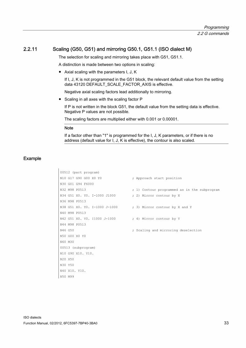
Example 00512 (part program)
N10 G17 G90 G00 X0 Y0 ; Approach start position
N30 G01 G94 F6000
N32 M98 P0513 ; 1) Contour programmed as in the subprogram
N34 G51 X0. Y0. I-1000 J1000 ; 2) Mirror contour by X
N36 M98 P0513
N38 G51 X0. Y0. I-1000 J-1000 ; 3) Mirror contour by X and Y
N40 M98 P0513
N42 G51 X0. Y0. I1000 J-1000 ; 4) Mirror contour by Y
N44 M98 P0513
N46 G50 ; Scaling and mirroring deselection
N50 G00 X0 Y0
N60 M30
00513 (subprogram)
N10 G90 X10. Y10.
N20 X50
N30 Y50
N40 X10. Y10.
N50 M99

Programming 2.2 G commands
ISO dialects 34 Function Manual, 02/2012, 6FC5397-7BP40-3BA0
Figure 2-2 Scaling and mirroring
System parameter setup for the scaling and mirroring example:
MD22910 $MC_WEIGHTING_FACTOR_FOR_SCALE = 0
MD22914 $MC_AXES_SCALE_ENABLE = 1
MD10884 $MN_EXTERN_FLOATINGPOINT_PROG = 0
MD10886 $MN_EXTERN_INCREMENT_SYSTEM = 0
When MD22914 $MC_AXES_SCALE_ENABLE = 0, axial scaling is not possible.
When scaling, the reference point is always the workpiece zero, the reference point cannot be programmed.
Mirroring G51.1 can be used to mirror workpiece shapes on coordinate axes.
Mirroring takes place on a mirroring axis which is parallel to X, Y or Z and whose position is programmed with X, Y or Z. G51.1 X0 is used to mirror on the X axis, G51.1 X10 is used to mirror on a mirroring axis that runs 10 mm parallel to the X axis.
All axes in the channel and not just the geometry axes can be mirrored.
G51.1 has an additive effect, i.e. following N5 G51.1 X10 and N10 G51.1 Y10, mirroring in X and V is active.
Example: G51.1 X80.
Mirroring is undertaken on a mirroring axis which is parallel to Y and which the X axis bisects at position 80.

Programming 2.2 G commands
ISO dialects Function Manual, 02/2012, 6FC5397-7BP40-3BA0 35
Figure 2-3 Mirroring on a mirroring axis parallel to Y
If standard notation is active (see Section "Decimal point programming"), the axis positions without a decimal point are interpreted in internal units.
Mirroring with G50.1 X0 Y0 is deselected. Deselection by axis is also possible. Following G50.1 X0, only mirroring in the X axis is deselected, all mirroring in other axes remains active.
G51.1 and G50.1 make up a block.
G51.1 is mapped in the channel-specific basic frame [1]. MD28081 $MC_MM_NUM_BASE_FRAMES >=2 must be set for this.
If the basic frame [1] is changed in Siemens mode, this impacts directly on function in ISO mode.
If the frame is deleted in all frame components, this corresponds to G50.1 X0 Y0.. in all axes.
G51.1 is deselected with Reset.
See also Decoupling the frames between Siemens and ISO mode (Page 22)

Programming 2.2 G commands
ISO dialects 36 Function Manual, 02/2012, 6FC5397-7BP40-3BA0
2.2.12 G60 directed positioning G60 is used in ISO dialect original to compensate for backlash. In Sinumerik, this is achieved using internal backlash compensation, which is why Siemens mode does not have a G function to match the G60 used in ISO dialect original.
A G macro call cannot take the place of G60 because two subprogram calls cannot be undertaken in an NC block. Because directed positioning (backlash) must be executed before the NC block is processed, calling a G macro at the end of the block would be too late.
Since G60 is used to compensate for backlash and this function can be activated using the axial machine data $MA_BACKLASH[ ], G60 is skipped in ISO mode without triggering a response.
If the G60 programming is to be taken into account when processing shell cycles, this information is made available in cycle variable $C_G60_PROG. If G60 is programmed, $C_G60_PROG = 1 is set and $C_G60_PROG is deleted again when returning to the subprogram. If a block also needs to contain information as to whether the cycle call is programmed, this is obtained from cycle variable $C_G_PROG. A G60 functionality can be added in the shell cycles using the information from these two system variables. The information regarding whether a modal cycle is active can also be found in system variable $P_MC ($P_MC = 1 -> a modal subprogram is active).
$C_G60_PROG is only set to 1 if G60 is programmed in an NC block as if G60 were a non-modal effective G function.
Example:
N32 G00 X0. Y0. Z0. R0.
N33 G60 X11.8407 Y2.4418 ;$C_G60_PROG = 1, $C_G_PROG = 0, $P_MC = 0
N34 G60 G83 X11.8407 Y2.4418 Z-6.9051 R-5.9 Q0.25F8
;$C_G60_PROG = 1,
;$C_G_PROG = 1, $P_MC = 1
N35 G60 X9.3969 Y2.6099 ;$C_G60_PROG = 1, $C_G_PROG = 0, $P_MC = 1
N36 X6.4128 Y2.4511 ;$C_G60_PROG = 0, $C_G_PROG = 0, $P_MC = 1
N37 G60 X4.0368 Y2.3131 ;$C_G60_PROG = 1, $C_G_PROG = 0, $P_MC = 1
N38 G60 X1.3995 Y2.5461 :$C_G60_PROG = 1, $C_G_PROG = 0, $P_MC = 1
N39 G80 ;$C_G60_PROG = 0, $C_G_PROG = 0, $P_MC = 0
cycle383m.spf
PROG CYCLE383M
....
IF $C_G60_PROG == 1
;G60 functionality
ENDIF
;Continue with shell cycle functionality

Programming 2.2 G commands
ISO dialects Function Manual, 02/2012, 6FC5397-7BP40-3BA0 37
2.2.13 2D/3D rotation G68/G69 (ISO dialect M)
2D rotation The coordinate system is rotated around the vertical axis of the activated plane.
Programming G68 X.. Y.. R.. X.. Y..: Coordinates of the pivot point, in relation to the current workpiece zero. If no
coordinate is programmed, the pivot point lies in the actual value. The value is always interpreted as absolute.
R: The angle of rotation, depending on G90/G91, has an absolute or incremental effect. If no angle is programmed, the angle from the setting data 42150 $SA_DEFAULT_ROT_FACTOR_R is active. G68 must be alone in the block.
G69 Rotation OFF; other commands can be programmed in this block.
G68 is mapped on the channel-specific basic frame 2. MD 28081 $MC_MM_NUM_BASE_FRAMES >= 3 must be set for this.
A programmed angle R is not entered in setting data 42150 $SA_DEFAULT_ROT_FACTOR_R. This setting data can only be written by hand and then only takes effect if there is no R programmed in the G68 block.
3D rotation The G code G68 is extended for 3D rotation.
Programming 2.2 G commands
ISO dialects 38 Function Manual, 02/2012, 6FC5397-7BP40-3BA0
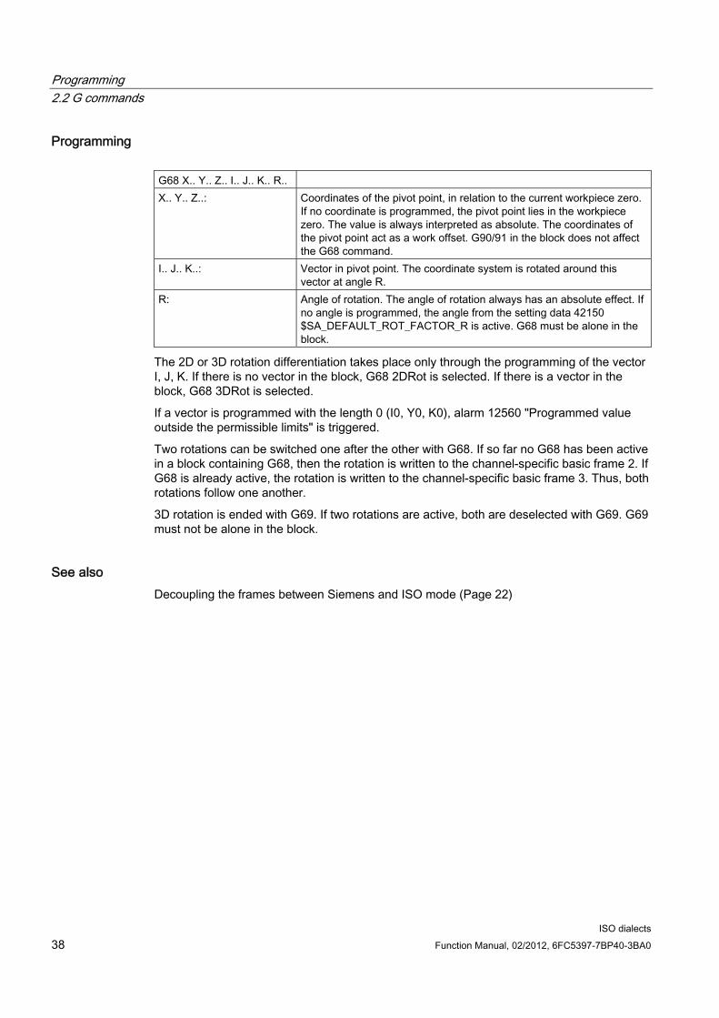
Programming G68 X.. Y.. Z.. I.. J.. K.. R.. X.. Y.. Z..: Coordinates of the pivot point, in relation to the current workpiece zero.
If no coordinate is programmed, the pivot point lies in the workpiece zero. The value is always interpreted as absolute. The coordinates of the pivot point act as a work offset. G90/91 in the block does not affect the G68 command.
I.. J.. K..: Vector in pivot point. The coordinate system is rotated around this vector at angle R.
R: Angle of rotation. The angle of rotation always has an absolute effect. If no angle is programmed, the angle from the setting data 42150 $SA_DEFAULT_ROT_FACTOR_R is active. G68 must be alone in the block.
The 2D or 3D rotation differentiation takes place only through the programming of the vector I, J, K. If there is no vector in the block, G68 2DRot is selected. If there is a vector in the block, G68 3DRot is selected.
If a vector is programmed with the length 0 (I0, Y0, K0), alarm 12560 "Programmed value outside the permissible limits" is triggered.
Two rotations can be switched one after the other with G68. If so far no G68 has been active in a block containing G68, then the rotation is written to the channel-specific basic frame 2. If G68 is already active, the rotation is written to the channel-specific basic frame 3. Thus, both rotations follow one another.
3D rotation is ended with G69. If two rotations are active, both are deselected with G69. G69 must not be alone in the block.
See also Decoupling the frames between Siemens and ISO mode (Page 22)

Programming 2.2 G commands
ISO dialects Function Manual, 02/2012, 6FC5397-7BP40-3BA0 39
2.2.14 Double slide or double turret processing G68/G69
Function The G68/G69 function can be used to control the processing of rotating parts on both sides. Both processing with a double slide in two channels and processing in one channel with two tools which are permanently linked to one another at a distance x.
MD10812 $MN_EXTERN_DOUBLE_TURRET_ON is used to define whether processing in the two channels is synchronized (= FALSE) or whether the two permanently linked tools are used in turn for processing (= TRUE).
When using permanently linked tools, G68 is used to activate distance x entered in setting data 42162 $SC_EXTERN_DOUBLE_TURRET_DIST as an additive work offset in the X axis. Because the second tool processes the opposite side of the rotating part, G68 is also used to activate mirroring around the Z axis (X axis direction change). The work offset and mirroring for the 2nd tool are activated with the next block with axial motion.
G69 is used to reverse the work offset and processing continues with the 1st tool.
G68 and G69 must be programmed in a block on their own.
During tool length compensation in the X axis for the second tool, the correction sign must be taken into account. The sign must be entered as if the X axis were not mirrored. Alternatively the setting data 42900 $SC_MIRROR_TOOL_LENGTH (mirror tool length compensation) and 42190 $SC_MIRROR_TOOL_WEAR (mirror wear values of tool length compensation) must be set.
MD10610 $MN_MIRROR_REF_AX must either be 0 or 1. The X or 1st axis is then always mirrored.
If G68 is programmed and G68 is already active, the G function is skipped. The same applies to G69.
Double turret head: $MN_EXTERN_DOUBLE_TURRET_ON = TRUE The example below shows processing with two permanently linked tools. Machine data $MN_EXTERN_DOUBLE_TURRET_ON = TRUE must be set for the function to be effective.
If the setting data 42162 $SC_EXTERN_DOUBLE_TURRET_DIST = 0, alarm 12728 "Distance for double turret not set" is output.

Programming 2.2 G commands
ISO dialects 40 Function Manual, 02/2012, 6FC5397-7BP40-3BA0
Figure 2-4 Processing with two permanently linked tools
Example:
N100 X40. Z180. G1 F1 G95 S1000 M3 T1 N110 G68 ;Activate mirroring around Z and additive work offset
(220 mm) N120 X80. Z120. T2 N130 G69 ;Deactivate mirroring and additive work offset N140 X120. Z60 T1
Double slide processing: $MN_EXTERN_DOUBLE_TURRET_ON = FALSE If MD10812 $MN_EXTERN_DOUBLE_TURRET_ON = FALSE, G68 undertakes channel synchronization. If G68 is programmed in a channel, processing is stopped until G68 is detected in the second channel. This function can be used to synchronize the 1st and 2nd channel. No more synchronization is undertaken. For the two tools to act in a synchronous manner in subsequent processing, the programmed movements and feeds must be the same in the two channels.

Programming 2.2 G commands
ISO dialects Function Manual, 02/2012, 6FC5397-7BP40-3BA0 41
Wait mark 1 is used for G68 and wait mark 2 is used for G69 to synchronize the first two channels. The first two M functions must not therefore be used at the same time for channel synchronization in the same part program (see chap. "Program coordination between two channels and M commands").
G68 only takes effect in the first two channels. If G68 is programmed in another channel and if MD10812 $MN_EXTERN_DOUBLE_TURRET_ON = FALSE, G68 is skipped.
The function is used for producing thin rotating parts. The two tools should therefore perform the same movement on the respective opposite side of the rotating part, mirrored around the Z axis. The same traversing and feeds must be programmed in the two channels for this to take place.
Example of synchronous processing with two channels:
Figure 2-5 Synchronous processing with two channels

Programming 2.2 G commands
ISO dialects 42 Function Manual, 02/2012, 6FC5397-7BP40-3BA0
Example:
Channel 1:
N10 ... - " - N1000 G68 ;Start synchronization N1010 G01 X30 Z120 G95 F1.2 S1000 M3 N1020 X15 Z80 N1030 Z65 N1040 Z25 X40 N1050 G69 ;Synchronization off
Channel 2:
N10 ... - " - N2000 G68 ;Start synchronization N2010 X30 Z120 G01 G95 F1.2 S1000 M3 N2020 X15 Z80 N2030 Z65 N2040 X40 Z25 N2050 G69 ;Synchronization off
In ISO dialect original, channel synchronization is also undertaken when G68 is active.

Programming 2.2 G commands
ISO dialects Function Manual, 02/2012, 6FC5397-7BP40-3BA0 43
2.2.15 Polar coordinates G15/G16 (ISO dialect M)
Programming When in ISO dialect mode, NC program parts in which polar programming is undertaken are started using start command G16. Until the end command G15 is issued, the coordinates of the end points are interpreted as radius and angle polar coordinate values in the current plane.
The first of the plane's axes is interpreted as a pole radius and the second axis as a pole angle, i.e. for G17, X is the radius and Y the angle.
After G16, in each block up to G15 the pole is reset and the pole is reset at G17:
● G90 X: The pole lies at the workpiece zero
● G91 X: The pole lies at the current position
● No X in block: The pole lies at the workpiece zero
If the pole is moved from the current position to the workpiece zero, the radius is calculated as the distance from the current position to the workpiece zero.
Example:
G1 F200 ; Feed
N5 G17 G90 X0 Y0
N10 G16 X100. Y45. ; Polar coordinates ON, pole is ; workpiece zero, Position X 70.711 Y ; 70.711 in the Cartesian coordinate system
N15 G91 X100 G90 Y0 ; pole is current position, position X ; 170.711 Y 70.711
N20 Y90. ; No X in the block, pole is at ; workpiece zero, ; Radius = SORT(X*X +Y*Y) = 184.776
The pole radius is always taken as absolute value, while the pole angle can be interpreted as absolute value as well as incremental value.
Programmed angle When polar coordinates programming is active, the programmed angle can be read via system variable $P_AP.
This variable is used in the shell cycle. Before the pole is reset, the angle must be saved during incremental programming because the angle is deleted.
Pole programming is ended with G15. The pole radius is set to 0.

Programming 2.2 G commands
ISO dialects 44 Function Manual, 02/2012, 6FC5397-7BP40-3BA0
2.2.16 Interpolation of polar coordinates G12.1/G13.1 (G112/G113)
Function With G12.1 and G13.1 an interpolation is activated and deactivated in the machining plane between a rotary axis and a linear axis. A further linear axis may be present perpendicular to this plane. This function corresponds to the TRANSMIT function in Siemens mode. In Siemens mode, two TRANSMIT transformations may be parameterized. The 1st TRANSMIT data block which must correspond to the 2nd transformation data block is always used for G12.1.
Note
A detailed description of the TRANSMIT function can be found in the NC function description "SINUMERIK 840D sl, Extended Function", Section "Kinematic Transformation (M1)" and in the work planning programming manual (PGA) in Section "Transformation".
Example
Figure 2-6 Example of the interpolation of polar coordinates

Programming 2.2 G commands
ISO dialects Function Manual, 02/2012, 6FC5397-7BP40-3BA0 45
00001
N010 T0101
N0100 G90 G00 X60.0 C0 Z..
N0200 G12.1 ;TRANSMIT selection
N0201 G42 G01 X20.0 F1000
N0202 C10.0;
N0203 G03 X10.0 C20.0 R10.0
N0204 G01 X-20.0
N0205 C-10.0
N0206 G03 X-10.0 C-20.0 I10.0 J0
N0207 G01 X20.0
N0208 C0
N0209 G40 X60.0
N0210 G13.1 ;TRANSMIT deselection
N0300 Z..
N0400 X.. C..
N0900 M30
Note
No geo axis interchange (parallel axes with G17 (G18. G19)) should be active.
Programming 2.2 G commands
ISO dialects 46 Function Manual, 02/2012, 6FC5397-7BP40-3BA0
2.2.17 Cylindrical interpolation G07.1 (G107)
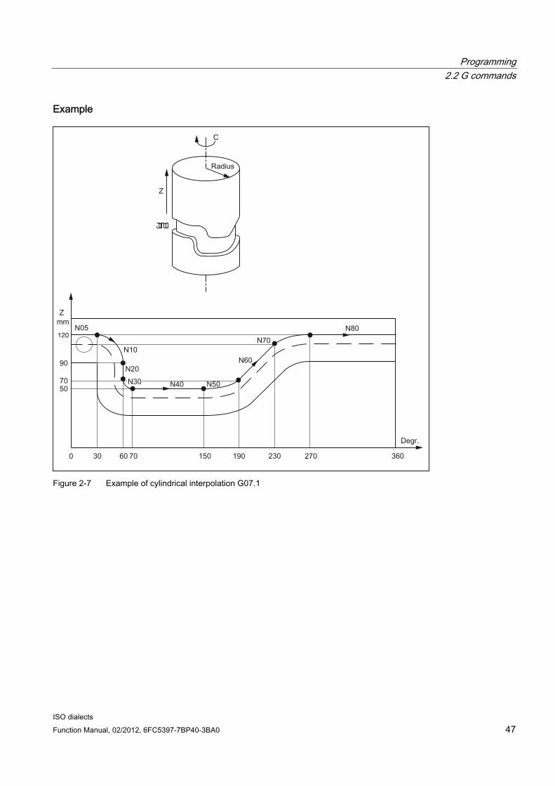
Function Randomly running grooves can be cut on cylindrical workpieces with function G07.1 (cylindrical interpolation). The path of the grooves is programmed with reference to the unwrapped, level surface of the cylinder. The cylindrical interpolation is started with G07.1 with the specification of the cylinder radius (G07.1 C<cylinder radius>) and ended with G07.1 C0 (radius = 0).
Note
The function is mapped internally on the TRACYL Siemens functionality. In ISO dialect mode, the 1st TRACYL transformation and the 1st transformation data block are always activated with G07.1. The 2nd TRACYL function cannot be activated in ISO dialect mode. A detailed description and parameterization of the 1st TRACYL function can be found in the following documentation:
Description of functions for extended functions, chapter M1 and Programming Manual for preparing for work, chapter 7 "Transformations".
Constraints For Siemens the rotary axis must be defined for cylindrical interpolation in machine data.
With ISO dialect, the rotary axis is defined for cylindrical interpolation with G07.1 programming <Rotary axis name>....
Programming 2.2 G commands
ISO dialects Function Manual, 02/2012, 6FC5397-7BP40-3BA0 47
Example
120
Figure 2-7 Example of cylindrical interpolation G07.1

Programming 2.2 G commands
ISO dialects 48 Function Manual, 02/2012, 6FC5397-7BP40-3BA0
Example of programming in ISO dialect mode:
%0001
N05 G00 G90 Z100.0 C0
N10 G01 G91 G18 Z0 C0
N20 G07.1 C57299 ;select cylindrical interpolation with radius 57.299 mm
N30 G90 G01 G42 Z120.0 D01 F250
N40 C30.0
N50 G02 Z90.0 C60.0 R30.0
N60 G01 Z70.0
N70 G03 Z60.0 C70.0 R10.0
N80 G01 C150.0
N90 G03 Z70.0 C190.0 R75.0
N100 G01 Z110.0 C230.0
N110 G02 Z120.0 C270.0 R75.0
N120 G01 C360.0
N130 G40 Z100.0
N140 G07.1 C0 ;deselect cylindrical interpolation
N150 M30 ;
Example of programming in Siemens mode: The Y axis is assigned to the rotary axis as a linear axis.
%0001
N05 G00 G90 Z100 C0
N10 G01 G91 G18 Z0 C0;
N20 TRACYL(114.598) ;select cylindrical interpolation with radius 57.299 mm
N30 G90 G01 G42 Z120 D01 F250
N40 Y30
N50 G02 Z90 Y60 RND=30
N60 G01 Z70
N70 G03 Z60.0 Y70 RND=10
N80 G01 Y150
N90 G03 Z70 Y190 RND=75
N100 G01 Z110 Y230
N110 G02 Z120 Y270 RND=75
N120 G01 Y360
N130 G40 Z100
N140 TRAFOOF ;deselect cylindrical interpolation
N150 M30 ;

Programming 2.2 G commands
ISO dialects Function Manual, 02/2012, 6FC5397-7BP40-3BA0 49
2.2.18 Interrupt program with M96/M97 (ASUB)
M96 A subprogram can be defined as an interrupt routine with the M96 P<Program No.>.
The start of this program is triggered by an external signal. To start the interrupt routine, the 1st rapid NC input is used from among the eight inputs available in the Siemens mode. Another rapid input (1 to 8) can also be selected with MD10818 $MN_EXTERN_INTERRUPT_NUM_ASUP.
The function is mapped on the Siemens syntax SETINT(x) <CYCLE396> [PRIO=1].
The interrupt program programmed with Pxxxx is called in shell cycle CYCLE396 in ISO mode. The program number can be found in $C_PI. At the end of the shell cycle, MD10808 $MN_EXTERN_INTERRUPT_BITS_M96, bit 1 is evaluated and either positioned on the interruption point with REPOS or continued with the next block. The value programmed with "P" can be found in the new cycle variable $C_PI without a leading zero. This must be increased to four digits in the shell cycle before the subprogram is called.
Example:
N0020 M96 P5 Call in shell cycle progName = "000" << $C_PI ISOCALLprogName
See also how to handle 8-digit program numbers if MD20734 $MC_EXTERN_FUNCTION_MASK, bit 6 is set.
End of interruption (M97) The interrupt program is deactivated with M97. Only after the next activation with M96 can the interrupt routine be started with the external signal.
This corresponds to the Siemens syntax ENABLE(x).
x = Content of MD10818 $MN_EXTERN_INTERRUPT_NUM_ASUP
If the interrupt program programmed with M96 Pxx is to be called directly with the interrupt signal (without intermediate step with CYCLE396), then machine data 20734 $MC_EXTERN_FUNCTION_MASK, bit 10 must be set. The subprogram programmed with Pxx is then called in Siemens mode during a signal change from 0 -> 1.
The M function numbers for the interrupt function are set through machine data. MD10804 $MN_EXTERN_M_NO_SET_INT is used to determine the M number for activating an interrupt routine, MD10806 $MN_EXTERN_M_NO_DISABLE_INT is used to determine the M number for suppressing an interrupt routine.

Programming 2.2 G commands
ISO dialects 50 Function Manual, 02/2012, 6FC5397-7BP40-3BA0
Only M functions which are not standard M functions may be set. The default of the M functions is M96 and M97. To activate the function, bit 0 must be set in MD10808 $MN_EXTERN_INTERRUPT_BITS_M96. The M functions are not output to the PLC. The M functions are interpreted as normal auxiliary functions if bit 0 is not set.
At the end of the "interrupt" program, one normally traverses to the end position of the part program block following the interruption block. If the part program is to be processed further from the interruption point, there must be a REPOS instruction at the end of the "interrupt" program, e.g. REPOSA. For this, the interrupt program must be written in the Siemens mode.
The M functions for activating and deactivating an interrupt program must be present alone in the block. The system issues alarm 12080 "Channel %1 block %2 syntax error for text %3" if addresses other than "M" and "P" are programmed in the block.
Information about machining cycles In ISO dialect original you can set whether a machining cycle is to be interrupted immediately or only at the end using an interrupt routine. To do this, the shell cycles must evaluate MD10808 $MN_INTERRUPT_BITS_M96 bit 3. If bit=1, the interrupt must be locked at the start of the cycle with DISABLE(1) and activated again at the end of the cycle with ENABLE(1) so that the machining cycle is not interrupted.
Because the interrupt program is only started during edge change 0/1, the interrupt input must be monitored in the event of a locked interrupt during the cycle runtime with a synchronized action in the shell cycle. If the interrupt signal in the cycle is changed from 0 to 1, the interrupt signal must be set again following ENABLE(1) at the end of the shell cycle so that the interrupt program is then started. To be able to write the interrupt input in the shell cycle, MD10361 $MN_FASTIO_DIG_SHORT_CIRCUIT[1] must be parameterized.
Machine data The response of the interrupt program function can be determined from the following machine data:
MD10808 $MN_EXTERN_INTERRUPT_BITS_M96: Bit 0 = 0 Interrupt program is not possible as M96/M97 are normal M functions. Bit 0 = 1 Activation of an interrupt program with M96/M97 is allowed.
Bit 1= 0 The part program is further processed with the end position of the next block following the interrupt block (REPOSL RMEBL). Bit 1= 1 Continue processing part program from interrupt position. (Evaluation in interrupt program (ASUB), return with/without REPOSL)
Bit 2 = 0 The interrupt signal interrupts the current block immediately and starts the interrupt routine. Bit 2 = 1: The interrupt routine is started only at the end of the block.

Programming 2.2 G commands
ISO dialects Function Manual, 02/2012, 6FC5397-7BP40-3BA0 51
Bit 3 = 0 The machining cycle is interrupted immediately after an interrupt signal arrives. Bit 3 = 1 The interrupt program is started only at the end of the machining cycle (evaluation in the shell cycles)
Bit 3 must be evaluated in the shell cycles and the cycle process must be adapted accordingly.
Bit 1 must be evaluated in the interrupt program.
If Bit 1 = TRUE, REPOSL RMIBL must be used for positioning on the interruption point at the end of the program, otherwise REPOSL RMEBL must be used for positioning on the block end position.
Example:
N1000 M96 P1234 ;Activate ASUB 1234.spf. In the case of a rising edge of
;the first high-speed input,
;the 1234.spf program is started.
N3000 M97 ;Deactivation of ASUB
Before the call of the interrupt program no rapid lift (LIFTFAST) is performed. With the increasing edge of the interrupt signal, depending on MD10808 $MN_EXTERN_INTERRUPT_BITS_M96, the interrupt program is started immediately.
Siemens constraints The interrupt routine is treated as a normal subprogram. In other words, to be able to execute interrupt routines, at least one subprogram level must be free. (For Siemens there are 12 program levels, for ISO dialect there are 5.)
The interrupt routine is started only during an edge change of the interrupt signal from 0 to 1. If the interrupt signal remains permanently on 1, then the interrupt program is not restarted any more
ISO dialect constraints A program level is reserved for the interrupt routine such that all permissible program levels may be filled before the interrupt program is called.
Depending on the machine data, the interrupt program is also started when there is a static signal.

Programming 2.2 G commands
ISO dialects 52 Function Manual, 02/2012, 6FC5397-7BP40-3BA0
2.2.19 Comments In ISO dialect mode, round brackets are interpreted as comment signs. In Siemens mode, ";" is interpreted as a comment. To simplify matters, a ";" is also understood as a comment in ISO dialect mode.
If the comment start sign '(' is used inside a comment again, the comment is ended only if all the open brackets are closed again.
Example:
N5 (comment) X100 Y100
N10 (comment(comment)) X100 Y100
N15 (comment(comment) X100) Y100
In blocks N5 and N10, X100 Y100 is executed, in block N15 only Y100 because the first bracket is closed only after X100. Everything up to that point is interpreted as a comment.
2.2.20 Skip block The sign for skipping or suppression of blocks "/" can be used at any convenient position in a block, i.e. even in the middle of the block. If the programmed block skip plane is active on the date of the compilation, the block is not compiled from this point up to the end of the block. An active block skip plane has the same effect as a block end.
Example:
N5 G00 X100. /3 YY100 --> Alarm 12080, N5 G00 X100. /3 YY100 --> no alarm, if block skip plane 3 is active
Block skip signs within a comment are not interpreted as block skip signs
Example:
N5 G00 X100. ( /3 Part1 ) Y100 ;the Y axis is traversed even when the
;block skip plane 3 is active
The block skip planes /1 to /9 can be active. Block skip values <1 >9 lead to alarm 14060 "Channel %1 block %2 Impermissible skip plane for differential block skip".
The function is mapped to the existing Siemens skip planes. Unlike ISO Dialect original, / and /1 are separate skip planes that must also be activated separately.

Programming 2.2 G commands
ISO dialects Function Manual, 02/2012, 6FC5397-7BP40-3BA0 53
2.2.21 Auxiliary function output
M functions ISO dialect mode
M functions are output to the PLC as auxiliary functions. The only exceptions are M98 and M99. Predefined M functions are:
M17, M40, M41, M42, M43, M44, M45, M70, M96, M97, M98, M99.
Spindle axis switchover with M29 In ISO dialect mode, the spindle is switched to axis mode with M29. The M function number may however also be set differently using machine datum.
MD20095 $MC_EXTERN_RIGID_TAPPING_M_NR is used to pre-set the M function number. The machine datum is only effective in external language mode and is preset with M29. Only the M function numbers that are not used as standard M functions can be assigned. For example, the M function numbers M0-M5, M30, M98, M99 are not allowed.
The same function is executed in Siemens mode with M70.
MD20094 $MC_SPIND_RIGID_TAPPING_M_NR) is used to pre-set the M function number. The machine datum is only effective in Siemens mode and is preset with M70. An M function other than M70 can therefore also be set in Siemens mode for the spindle changeover. The machine datum may only be assigned M function numbers that are not used as standard M functions. M0 to M5, M17, M19, M30, M40 to M45 are not permitted.
H functions All H functions are output to the PLC in ISO dialect M as auxiliary functions. With ISO dialect T G Code System A, H is the incremental path of the 4th axis - only if a 4th axis is present.
T functions T functions are output to the PLC as auxiliary functions. T also means tool selection.
D functions The D function is output to the PLC as an auxiliary function. With ISO dialect M, the tool length compensation is activated under address D.
B functions If B is not an axis, the B function is output to the PLC as auxiliary function H with address extension H1=.
Example: B1234 is output as H1 = 1234.
Programming 2.2 G commands
ISO dialects 54 Function Manual, 02/2012, 6FC5397-7BP40-3BA0
2.2.22 Approach 1st home position with intermediate point (G28) The CYCLE328 cycle is called automatically when reading the ISO dialect command "G28 <axis>". The intermediate position (incremental or absolute) via which the home position is to be approached is stated under <Axis>. The intermediate position and reference position are approached in positioning mode.
The cycle only applies for the axes available with ISO dialect:
● ISO dialect M: X, Y, Z (A, B, C, U, V, W)
● ISO dialect T: X, Z, Y (C)
The cycle is always run with radius programming (DIAMOF). Active G commands become effective again once the cycle is complete and before the cycle is called.
Various machine data must be set before the 1st home position is approached, see "Commissioning" chap.
2.2.23 Switching precontrol on/off with G08 P..
Function The feedforward control reduces the velocity-dependent overtravel when contouring towards zero. Traversing with feedforward control permits higher path accuracy and thus improved machining results.
Note
The type of feedforward control and which path axes are to be traversed with feedforward control is specified via machine data.
Default: Velocity-dependent feedforward control Option: Acceleration-dependent feedforward control
Example N0010 G08 P1 ; Switch on feedforward control
N0020 G1 X10 Y50 F900
N0030 G1 X20 Y70
N1000 G08 P0 ; Switch off feedforward control
If G08 is programmed without "P", alarm 12470 "Channel %1 block %2 G function %3 is unknown" is output.
In order to use G08 P1 to flexibly activate other functions such as SOFT, BRISK etc., G08 P.. is used to call cycle CYCLE308.spf.
G08 P1 alone must remain in the block.

Programming 2.2 G commands
ISO dialects Function Manual, 02/2012, 6FC5397-7BP40-3BA0 55
2.2.24 Compressor in ISO dialect mode
The commands COMPON, COMPCURV, COMPCAD are commands of the Siemens language and they activate a compressor function that combines several linear blocks into one machining section. If this function is activated in Siemens mode, even linear blocks can then be compressed in ISO mode with this function.
The blocks can at the most consist of the following commands:
● Block number
● G01, modal or in block
● Axis assignments
● Feedrate
● Comments
If a block contains other commands (e.g., auxiliary functions, other G codes, etc.), then compression does not take place.
Value assignments with $x for G, axes and feedrate are possible, as is the skip function.
Example: These blocks are compressed:
N5 G290
N10 COMPON
N15 G291
N20 G01 X100. Y100. F1000
N25 X100 Y100 F$3
N30 X$3 /1 Y100
N35 X100 (Axis 1)
These blocks are not compressed:
N5 G290
N10 COMPON
N20 G291
N25 G01 X100 G17 ;G17
N30 X100 M22 ; Auxiliary function in block
N35 X100 S200 ;Spindle speed in block

Programming 2.2 G commands
ISO dialects 56 Function Manual, 02/2012, 6FC5397-7BP40-3BA0
2.2.25 Automatic corner override G62 An inner corner with active tool radius compensation is often meaningful to reduce the feedrate.
G62 operates only on inner corners with active tool radius compensation and active continuous-path mode. Only the corners whose inner angle is smaller than SD42526 $SC_CORNER_SLOWDOWN_CRIT are taken into account. The inner angle is defined from the bend in the contour.
The feedrate is reduced by the factor SD42524 $SC_CORNER_SLOWDOWN_OVR:
Traversed feedrate =
F * $SC_CORNER_SLOWDOWN_OVR * feedrate override.
The feedrate override is made up of the feedrate override of the Machine Control Panel multiplied by the override from synchronized actions.
The reduction in feedrate is begun at a distance of SD42520 $SC_CORNER_SLOWDOWN_START before the corner. It ends at distance SD42522 $SC_CORNER_SLOWDOWN_END after the corner (see following figure). An appropriate path is used for curved contours.
Figure 2-8 Parameter assignment of feedrate reduction G62 with the example of a 90 degree corner

Programming 2.2 G commands
ISO dialects Function Manual, 02/2012, 6FC5397-7BP40-3BA0 57
Parameter assignment The override value is set using the following setting data:
SD42520 $SC_CORNER_SLOWDOWN_START SD42522 $SC_CORNER_SLOWDOWN_END SD42524 $SC_CORNER_SLOWDOWN_OVR SD42526 $SC_CORNER_SLOWDOWN_CRIT
The setting data is preassigned with the value 0.
● If $SC_CORNER_SLOWDOWN_CRIT = 0, the corner deceleration is effective only at the reversal points.
● If $SC_CORNER_SLOWDOWN_START and $SC_CORNER_SLOWDOWN_END are equal to 0, then the feedrate reduction is approached with the permissible dynamic response.
● If $SC_CORNER_SLOWDOWN_OVR = 0, then a transient stop is inserted.
● $SC_CORNER_SLOWDOWN_CRIT is related to the geometry axes in G62. It defines the maximum inner angle in the current machining plane up to which the corner deceleration is used. G62 is not effective in rapid traverse.
Activating The function is activated via G62 and/or G621. The G code is active either via the corresponding part program command or through MD 20150 $MC_GCODE_RESET_VALUES[56].
Examples $TC_DP1[1,1]=120
$TC_DP3[1,1]=0. ;Tool length compensation
$TC_DP4[1,1]=0.
$TC_DP5[1,1]=0.
N1000 G0 X0 Y0 Z0 F5000 G64 SOFT
N1010 STOPRE
N1020 $SC_CORNER_SLOWDOWN_START = 5.
N1030 $SC_CORNER_SLOWDOWN_END = 8.
N1040 $SC_CORNER_SLOWDOWN_OVR = 20.
N1050 $SC_CORNER_SLOWDOWN_CRIT = 100.
N2010 X00 Y30 G90 T1 D1 G64
N2020 X40 Y0 G62 G41 ;Inner corner of N2030, ;but TRC still selected
N2030 X80 Y30 ;Inner corner of N2040 127 degrees
N2040 Y70 ;Inner corner of N2050 53 degrees
N2050 X40 Y40 ;Outer corner of N2060
N2060 X20 Y70 ;Inner corner of N2070 97 degrees
N2070 Y60 ;Inner corner of N2080 90 degrees
N2080 X20 Y20 ;Outer corner of N2090, ;irrelevant due to TRC deselection
N2090 X00 Y00 G40 FENDNORM
M30

Programming 2.3 Substitution by a substitution cycle with a tool selection block
ISO dialects 58 Function Manual, 02/2012, 6FC5397-7BP40-3BA0
2.3 Substitution by a substitution cycle with a tool selection block
2.3.1 Milling
Note
The following generally applies to all substitution cycles in which the programmed values are transferred in $C_ variables:
The $C_ system variables must be copied at the start of the cycle into R parameters, local and global user data. The cycle then only works with the copies.
Substitution by an M macro MD10814: $MN_EXTERN_M_NO_MAC_CYCLE[0] = 6 MD10815: $MN_EXTERN_M_NO_MAC_CYCLE_NAME[0] = "L6"
Nothing from this block is executed, all programmed parameters are copied into $C_ system variables.
In the cycle, T, H, D and M must be programmed and all other addresses programmed in the block written indirectly.
Example:
MD22550: $MC_TOOL_CHANGE_MODE = 1 MD22560: $MC_TOOL_CHANGE_M_CODE = 206
N5 T10 H22 M6 or N5 T10 D33 M6 ; M6 calls L6 N100 PROC L6( )
N105
N110 $C_MACPAR[1]=$C_T
N115 $C_MACPAR[2]=$C_H
N120 $C_MACPAR[3]=$C_D
N125 G291
N130 T$1 H$2 M206 or N130 T$1 D$2 M206
N135 G290
N140 RET
T can also be programmed in Siemens mode with T=$C_T.

Programming 2.3 Substitution by a substitution cycle with a tool selection block
ISO dialects Function Manual, 02/2012, 6FC5397-7BP40-3BA0 59
Substitution by an M function MD10715: $MN_M_FCT_CYCLE[0] = 6 MD10716: $MN_M_FCT_CYCLE_NAME[0] = "L6" MD10718: $MN_M_NO_FCT_CYCLE_PAR = 0 MD10719: $MN_T_NO_FCT_CYCLE_MODE
MD10718 is used to parameterize whether the cycle call takes place when the parameters are transferred. MD10719 is used to set the call time at the start or end of the block.
If just N5 T M6 and not H D is programmed in the part program block, the cycle can be called without the transfer of parameters. The block is executed and the cycle called without the transfer of parameters at the end of the block.
Only the M function has to be programmed in the cycle to activate the tool.
Example:
MD22550: $MC_TOOL_CHANGE_MODE = 1 MD22560: $MC_TOOL_CHANGE_M_CODE = 206 MD10715: $MN_M_FCT_CYCLE[0] = 6 MD10716: $MN_M_FCT_CYCLE_NAME[0] = "L6" MD10718: $MN_M_NO_FCT_CYCLE_PAR = -1
N5 T10 M6 ; M6 calls L6
N100 PROC L6( )
…
…
N110 m206
N115 RET
If N5 T H M6 or N5 T D M6 is programmed in the part program block, the cycle must be called with the transfer of parameters. T H D and the M function then have to be programmed in the cycle to activate the tool. H and D must be programmed after the T and M function to activate the tool.
Example:
MD22550: $MC_TOOL_CHANGE_MODE = 1 MD22560: $MC_TOOL_CHANGE_M_CODE = 206 MD10715: $MN_M_FCT_CYCLE[0] = 6 MD10716: $MN_M_FCT_CYCLE_NAME[0] = "L6" MD10718: $MN_M_NO_FCT_CYCLE_PAR = 0
N5 T10 H22 D23 M6 ; M6 calls L6
N100 PROC L6( )
N105 IF $C_T_PROG == 1
N110 $C_MACPAR[1]=$C_T
N115 G291
N120 T$1 M206
N125 G290
or
N110; programming of H and D
; indirectly via $C_MACPAR as in blocks N110 and N120
M115 M17
Programming 2.3 Substitution by a substitution cycle with a tool selection block
ISO dialects 60 Function Manual, 02/2012, 6FC5397-7BP40-3BA0
Substitution by T programming MD10717: $MN_T_FCT_CYCLE_NAME="L6" $MN_T_NO_FCT_MODE MD10719: $MN_T_NO_FCT_CYCLE_MODE
Nothing from this block is executed, all programmed values are written into $C_ system variables. The call time is determined with $MN_T_NO_FCT_MODE. T and M must be programmed in the cycle. If H or D are programmed in addition to T in the call block, H and D must be programmed in the cycle after the T and M function to activate the tool.
Example:
MD22550: $MC_TOOL_CHANGE_MODE = 1 MD22560: $MC_TOOL_CHANGE_M_CODE = 206
N5 T10; T calls L6.spf
N100 PROC L6( )
N105 T=$C_T M206
or in ISO mode indirectly via T$1
N110 $C_MACPAR[1]=$C_T
N120 G291
N125 T$1 M206
N125 G290

Programming 2.3 Substitution by a substitution cycle with a tool selection block
ISO dialects Function Manual, 02/2012, 6FC5397-7BP40-3BA0 61
2.3.2 Turning
Substitution by an M macro MD10814: $MN_EXTERN_M_NO_MAC_CYCLE[0] = 6 MD10815: $MN_EXTERN_M_NO_MAC_CYCLE_NAME[0] = "L6"
Nothing from this block is executed, all programmed parameters are written into $C_ system variables.
T must be programmed in the cycle. The programmed T contains the tool number and the correction number. The programmed value is transferred in $C_T. T1234 results in $C_T = 1234; $C_T_PROG = 1.
Example:
MD22550: $MC_TOOL_CHANGE_MODE = 1 MD22560: $MC_TOOL_CHANGE_M_CODE = 206
N5 T1022 M6 ; M6 calls L6
N100 PROC L6( )
N101 IF $C_T == TRUE
N110 $C_MACPAR[1]=$C_T
N120 G291
N125 T$1 M206
N130 G290
N135 ENDIF
N140 M17
Substitution by an M function MD10715: $MN_M_FCT_CYCLE[0] = 6 MD10716: $MN_M_FCT_CYCLE_NAME[0] = "L6"
The block is executed and the cycle called without the transfer of parameters at the end of the block.
The M function is programmed in the cycle at the end to activate the tool (if present).
Example:
MD22550: $MC_TOOL_CHANGE_MODE = 1
MD22560: $MC_TOOL_CHANGE_M_CODE = 206
N5 T1234 M6 ;M6 calls L6
PROC L6( )
…
M206
M17

Programming 2.3 Substitution by a substitution cycle with a tool selection block
ISO dialects 62 Function Manual, 02/2012, 6FC5397-7BP40-3BA0
Substitution by T programming MD10717: $MN_T_FCT_CYCLE_NAME="L6"
Nothing from the block is executed, all programmed values are written into $C_ system variables.
The call time is determined with $MN_T_NO_FCT_CYCLE_MODE. T and M must be programmed in the cycle. The programmed T value contains the tool number and tool compensation number.
The split T value and the tool number in $C_T and the programmed tool number in $C_H are transferred to the cycle according to MN_EXTERN_DIGITS_TOOL_NO or MN_EXTER_DIGITS_OFFSET_NO.
The unsplit programmed T value is also transferred in $C_T_VALUE.
Example:
Tool Cutting edge H number T10 D1 H1 D2 H2 T31 D1 H3 D2 H4
MN_EXTER_DIGITS_OFFSET_NO = 2
N5 T3104 ; tool 31 $C_T == 31
; H number 4$C_H == 4
; $C_T_VALUE == 3104
T is programmed indirectly in the cycle with $C_T_WORD.
Example:
N5 T3104 ; T calls L6.spf
PROC L6( ) ; T indirectly in ISO mode
N100
N102 $C_MACPAR[1] = $C_T_VALUE
N105 G291
N110 T$1
N115 G290
N120 M17
Programming 2.3 Substitution by a substitution cycle with a tool selection block
ISO dialects Function Manual, 02/2012, 6FC5397-7BP40-3BA0 63
2.3.3 Indirect programming in ISO mode using $ variables What are known as $ variables exist in order to perform indirect programming in ISO mode. Values are assigned in ISO mode via these $ variables, for example T$1. In total there are 30 $ variables, $1 to $30.
The $ variables are written in Siemens mode using $C_MACPAR[0] – [30]. When programming in ISO mode, the value is read from the corresponding $C_MACPAR[ ] variable and assigned to the address. The integer value following $ corresponds to the index for $C_MACPAR[ ].
Example:
N5 G290
N10 $C_MACPAR[5] = 12
N15 G291
N20 T$5
The value from $C_MACPAR[5] is assigned to address T. This corresponds to T12 in ISO mode.
Several $ assignments can be located in the same block.
N5 G290
N10 $C_MACPAR[1] = 1000 $C_MACPAR[2] = 85 $C_MACPAR[3] = 93.2
N15 G29
N20 F$1 X$2 Y$3 This corresponds to F1000 X85 Y93.2
Numerous calculations can therefore be undertaken in Siemens mode and the results then assigned to addresses in ISO mode.
Note
Pure calculations in ISO mode e.g.: N5 $1=$2+1200 are not possible.

Programming 2.4 Subprogram and macro technology
ISO dialects 64 Function Manual, 02/2012, 6FC5397-7BP40-3BA0
2.4 Subprogram and macro technology
2.4.1 Subprogram technique: M98
Subprogram call In ISO dialect, subprogram calls with M98 are programmed.
For the program syntax, see the figure below:
Figure 2-9 Description of permissible parameters
Program syntax M98 Pxxxxyyyy is used to call a subprogram with the number yyyy and repeat it xxxx times. If xxxx is not programmed, the subprogram is only executed once. The subprogram name always comprises four digits or is extended by adding 0s until there are four digits.
For example, if M98 P21 is programmed, a search is undertaken for the 0021.spf program name in the part program memory and the subprogram is run once. If the subprogram is to be run three times, M98 P30021 should be programmed.
To date the number of program passes (number of repeats) in ISO dialect M/T has been programmed with the subprogram number under address "P".
As an alternative to this programming syntax, the number of subprogram passes can now also be programmed under address "L". The subprogram number is still programmed with Pxxxx. If the number of passes is programmed with both addresses, the number of passes programmed with address "L" applies. The number of subprogram passes may be between 1 and 9999.
Example:
N20 M98 P20123 ;The 123.spf subprogram is executed twice
N40 M98 P55 L4 ;The 55.spf subprogram has been executed four times
N60 M98 P30077 L2 ;The 77.spf subprogram is executed twice
;The number of passes =3 programmed at address "P" is ignored.

Programming 2.4 Subprogram and macro technology
ISO dialects Function Manual, 02/2012, 6FC5397-7BP40-3BA0 65
End subprogram The subprogram is ended with M99.
If M99 Pxxxx is programmed, a move is made to block number Nxxxx when returning to the main program. The block number must always start with "N". The block number is first looked for in a forward direction (from subprogram call working towards program end). If no suitable block number is found, the part program is eventually searched in the reverse direction (in the direction of the start of the part program).
If M99 has no block number (Pxxxx) in a subprogram, the subprogram is ended and a jump made to the block after the subprogram call in the main program.
If M99 is without a block number (Pxxxx) in a main program, the control goes to the start of the main program and the main program is processed afresh.
These M commands are not output to the PLC.
M99 does not reset the program runtime. An activated tool counter is not incremented.
Subprogram return with "RET" Applies to ISO dialect T only.
After scrubbing, in the Siemens shell cycles for stock removal (as in ISO dialect) the program should continue in the main program following the contour description. To do this, the shell cycle must return to the block after the end of the contour description in the subprogram. In order to jump the blocks with the contour description during stock removal cycles after the subprogram call (with G71-G73), two optional parameters are added to the RET command.
Program processing in the program being called (main program) with the block <block number/label> is continued with the RET command (STRING <block number/label>).
If program processing is to be continued with the next block after <block number/label>, the 2nd parameter in the RET command must be programmed > 0 RET (<block number/label>, 1). If a value > 1 is programmed for the 2nd value, the subprogram also returns to the block after the block with <block number/label>.
The contour to be processed is saved in the main program for cycles G70-G73. The extended RET command is needed to start at the end of G70 (finishing cut above contour with stock removal cycle) in the main program after the contour description. To jump to the next NC block after the contour description at the end of the shell cycle for G70, this must end with the following return syntax:
RET ("N" << $C_Q, 1)
Search direction:
The search direction for <block number/label> is always firstly forward direction (heading towards program end) and then reverse direction (heading towards program start).

Programming 2.4 Subprogram and macro technology
ISO dialects 66 Function Manual, 02/2012, 6FC5397-7BP40-3BA0
Example N10 X10. Y20.
N20 G71 P30 Q60 U1 W1 F1000 S1500
N10 ... ;Shell cycle for stock removal cycle
N20 DEF STRING[6]BACK
N30 ...
N90
N100 RET ("N"<<$C_Q, 1) ;Jump back to block after ;contour definition -> N70
N30 X50. Z20.
N40 X60.
N50 Z55.
N60 X100. Z70.
N70 G70 P30 Q60
N80 G0 X150. Z200.
N90 M30
Note
In Siemens mode, M30 is interpreted in the subprogram as a program return jump.
In ISO dialect mode, M30 is also interpreted in the subprogram as part program / end of program.
Programming 2.4 Subprogram and macro technology
ISO dialects Function Manual, 02/2012, 6FC5397-7BP40-3BA0 67
2.4.2 Siemens language commands in ISO dialect mode
Programming Certain Siemens language commands are also needed in ISO dialect mode for ShopMill. These are then run in ISO dialect mode. These language commands include subprogram calls with and without the transfer of parameters (not calls with Lxx because address L already has a different meaning with ISO dialect), program part repeat and control structures. All other Siemens language commands are rejected with an alarm in ISO dialect mode.
When ISO dialect mode is active, the following Siemens language commands may be programmed:
REPEAT:
REPEAT Block number > [<block number>] [P..] REPEAT UNTIL REPEATB <block number> [P..]
Only block numbers and not labels are permitted as start and end delimiters.
IF - ELSE - ENDIF
FOR - ENDFOR
WHILE - ENDWHILE
IF<condition> - GOTO F<condition>
CASE
Modal and non-modal subprogram calls N100 CALL "SHAFT" or
N100 MCALL SHAFT" or
N100 SHAFT
Modal and non-modal subprogram calls with transfer of parameters N100 MCALL SHAFT ("ABC"; 33.5 ) or
N100 SHAFT ("ABC"; 33.5 ) subroutine calls with path name
N100 CALL"/_N_SPF_DIR/SHAFT or
N100 MCALL/_N_SPF_DIR/SHAFT or
N100 PCALL/_N_SPF_DIR/SHAFT
Programming 2.4 Subprogram and macro technology
ISO dialects 68 Function Manual, 02/2012, 6FC5397-7BP40-3BA0
2.4.3 Expansion of subprogram call for contour preparation with CONTPRON
Expansion With ISO dialect the contour description for the stock removal cycles G70-G73 is not saved separately in a subprogram (as with SINUMERIK), but in the part program (main program). When calling the cycles, the range of the contour description is defined with a start and end block number. The cycles contain these block numbers as transfer parameters. The indirect subprogram call is expanded for the Siemens adjustment cycles.
Until now a subprogram call has been called indirectly with CALL <program name>.
The indirect subprogram call is expanded as follows for accessing the contour description in the main program:
CALL [<program name>] BLOCK <start label> TO <end label>
If there is no program name stated or if an empty string is stated as the program name, i.e. CALL BLOCK <Start label> TO <End label>, the program part (start/end label) is sought in the program currently selected. The labels are also sought in the selected program for MDA, ASUB etc. (e.g. in the case of MDA, labels are not sought in the MDA buffer but in the program with the selected program name). If this syntax is written directly in a main program, it acts like a program part repeat with REPEAT <Start label> <End label> with a loop pass, i.e. start and end label are sought in the same program, in which the CALL BLOCK ... command is also programmed.
If a program name is stated, i.e. CALL <progName> BLOCK <Start label> TO <End label>, the program part (start/end label) is sought in the "progName" subprogram.

Programming 2.4 Subprogram and macro technology
ISO dialects Function Manual, 02/2012, 6FC5397-7BP40-3BA0 69
Example Nxx G71 Pxx Q1110 U.. W.. ;ISO dialect G function calls shell cycle
;CYCLE395.spf
;_N_CYCLE395_SPF
N10 .......
.......
Nxxx CYCLE95(....., "N"<<$C_P, "N"<<$C_Q)
;Stock removal cycle with additional parameters ;for start and end label
PROC CYCLE95(....., STRING[20] start lab, STRING[20]
end lab)
N10 ........
.........
Nxxx CONTPRON(...)
N.... CALL "" BLOCK start lab TO end lab
;Read contour definition or
N.... CALL BLOCK start lab TO end lab
;Call contour program
EXECUTE(...)
........
Nxx M17
Nxxx .....
Nxxx RET ("N"<<$C_Q, 1) ;Return to next block after ;contour definition
N1120 ....
Nxxx M30
Note
CONTPRON and EXECUTE calls themselves must not be changed.
Searching for start block number The search for the start block number (start label) of the contour description always takes place first working towards the program end (forwards) and then working towards the program start (backwards).
If the same block number is programmed several times, the next block number (label) after the current block in the program containing the contour description is recognized as the start of the contour description (see example). The current block is usually the block in which the stock removal cycle (shell cycle) was called in the main program.

Programming 2.4 Subprogram and macro technology
ISO dialects 70 Function Manual, 02/2012, 6FC5397-7BP40-3BA0
Example:
In stock removal cycle CYCLE395, the contour description found in the main program between blocks N10-N30 is to be used (with CALL BLOCK N10 TO N30 in CYCLE395). N40 is the current program line in the main program.
The contour description block in our example is shown in bold.
N5 G1 F500
N10 X10. Y20.
N20 X30.
N30 Y10.
N40 G71 P10 Q30... ;Call shell cycle for stock removal cycle
... ;(In the stock removal cycle,
... ;"CALL BLOCK N10 TO N30" is programmed)
... ;The bold lines are found as the
;contour definition
N50 G90 G54
N60 F1000 G94
N10 X50. Y10.
N20 X33. Y11.
N30 X10.
N50 ....
N.. .....
N800 G71 P10 Q30 ;Call shell cycle for stock removal cycle
... ;(In the stock removal cycle, "CALL BLOCK N10 TO N30"
;is programmed)
... ;The lines printed in
... ;italics are found as the contour definition
N999 ....
N10 X15.
N20 Y25.
N30 X33.
N1010 ...
N1020 .....
Programming 2.4 Subprogram and macro technology
ISO dialects Function Manual, 02/2012, 6FC5397-7BP40-3BA0 71
2.4.4 Macro commands with G65, G66 and G67
ISO dialect In ISO dialect mode, G65 Pxx and G66 Pxx are used to call macros in the part program. The combination of several part program blocks which are terminated with M17 is known as a macro.
When calling the subprogram, a switch is made from ISO mode to Siemens mode.
The following commands are used for selection and deselection:
● G65 macro call, non-modal effective
● G66 macro call, modal effective
● Deselect G67 modal macro call
Siemens G commands G65 Pxx and G66 Pxx start macro xx. G65 calls the Pxx subprogram once, G66 makes subprogram call Pxx modal and it is executed in each block with axial motion (as MCALL xx). G67 deselects the modal subprogram call again (corresponds to G80 for cycle calls).
In a part program block containing G65 or G66, the address Pxx is interpreted as the program number of the subprogram in which the macro functionality is programmed. The number of passes of the macro can be defined with the address Lxx. If the number of passes is not programmed in the call block, the macro is run once. All other addresses in this part program block are interpreted as transfer parameters and their programmed values are stored in the system variables $C_A to $C_Z. These system variables can be read in the subprograms and evaluated for the macro functionality. If other macros with parameter transfer are called in a macro (subprogram), then the transfer parameters in the subprogram must be saved in internal variables before the new macro call.
To enable internal variable definitions, one must switch automatically to the Siemens mode during macro call. If another macro call is programmed in the subprogram, then the ISO dialect mode must be reselected in advance.
System variables for the addresses I, J, K As the addresses I, J, and K can be programmed up to ten times in a block containing macro call, the system variables of these addresses must be accessed with an array index. The syntax of these three system variables thus is $C_I[..], $C_J[..], $C_K[..]. The values remain in the programmed sequence in the array. The number of I, J, K addresses programmed in the block is given in the variables $C_I_NUM, $C_J_NUM, $C_K_NUM.
The transfer parameters I, J, K for macro calls are treated in each case as one block even if the individual addresses are not programmed. If a parameter is reprogrammed, or a following parameter based on the I, J, K sequence has been programmed, it belongs to the next block.

Programming 2.4 Subprogram and macro technology
ISO dialects 72 Function Manual, 02/2012, 6FC5397-7BP40-3BA0
The system variables $C_I_ORDER, $C_J_ORDER, $C_K_ORDER are set to detect the programming sequence in ISO mode. These are identical arrays to $C_I, $C_K and they contain the associated numbers of the parameters.
Note
The transfer parameters can only be read in the subprogram.
Example:
N5 I10 J10 K30 J22 K55 I44 K33
Block1 Block2 Block3
$C_I[0]=10
$C_I[1]=44
$C_I_ORDER[0]=1
$C_I_ORDER[1]=3
$C_J[0]=10
$C_J[1]=22
$C_J_ORDER[0]=1
$C_J_ORDER[1]=2
$C_K[0]=30
$C_K[1]=55
$C_K[2]=33
$C_K_ORDER[0]=1
$C_K_ORDER[1]=2
$C_K_ORDER[2]=3
Cycle parameter $C_x_PROG In the ISO dialect 0 mode, the programmed values can be evaluated in different ways, depending on the programming method (integer or actual value). The different evaluation is activated using machine data.
If the MD is set, the control system responds as in the following example:
X100. X axis is traversed by 100 mm (100. with point => actual value)
Y200 ; Y-axis is traversed by 0.2 mm (200 without point => integer value)
If the addresses programmed in the block are used as transfer parameters for cycles, then the programmed values always exist as real values in the $C_x variables. For integer values, one cannot take recourse to the programming method (real/integer) in the cycles any more, and therefore there is no evaluation of the programmed values with the correct conversion factor.

Programming 2.4 Subprogram and macro technology
ISO dialects Function Manual, 02/2012, 6FC5397-7BP40-3BA0 73
To find out whether REAL or INTEGER has been programmed, refer to system variable $C_TYP_PROG, which is structured just like $C_ALL_PROG and $C_INC_PROG. There is one bit for each address (A-Z). If the value is programmed as INTEGER, bit 0 is set, if it is REAL, 1 is set. If the value is programmed using a variable $<Number>, bit 2 = 1 is set.
Example:
P1234 A100. X100 -> $C_TYP_PROG == 1.
Only bit 0 is present, because only A was programmed as REAL.
P1234 A100. C20. X100 -> $C_TYP_PROG == 5.
Bit 1 and bit 3 (A and C) are present.
Restrictions:
A maximum of ten I, J, K parameters can be programmed in each block. Only one bit each is provided for I, J, K in the variable $C_TYP_PROG. Hence in $C_TYP_PROG bits is always set to 0 for I, J and K. Therefore it cannot be derived whether I, J or K is programmed as REAL or as INTEGER.
Parameters P, L, O, N can only be programmed as integers. A real value results in an NC alarm. The bit in $C_TYP_PROG is therefore always 0.
Modal macro calls For modal macro calls, the programmed addresses are only written to the system variables in the call block (block with G66). The macro is then executed in each block with axial motion until deselected with G67 or until a new macro call is programmed with G66. Only macro parameters are provided for modal macros in the call block (= block with G66). The macro is first run in the next block with axial motion. (Process as with MCALL xx in Siemens mode.)
Example of macro call:
_N_M10_MPF:
N10 M3 S1000 F1000
N20 X100. Y50. Z33.
N30 G65 P10 F55 X150. Y100. S2000
N40 X50.
N50 ....
N200 M30
Example of a subprogram as a macro in Siemens mode:
_N_10_SPF:
N10 DEF REAL X_AXIS Y_AXIS, SPEED, FEEDRATE
N15 X_AXIS = $C_X Y_AXIS = $C_Y SPEED = $C_S FEEDRATE = $C_F
N20 G01 F=FEEDRATE G95 S=SPEED
...
M17

Programming 2.4 Subprogram and macro technology
ISO dialects 74 Function Manual, 02/2012, 6FC5397-7BP40-3BA0
2.4.5 Changing mode during macro calls with G65/G66 In the past during macro calls with G65/G66, a switch has been automatically made into Siemens mode.
The user can now decide whether a switch is to be made to Siemens mode at the start of the macro. If the first program line of the macro program contains the operation PROC<Program name>, a switch is made into Siemens mode. If this operation isn't there, ISO mode is retained in the macro program.
The user can then decide whether to create local variables (with DEF...) to save transfer variables. To do this, the user must switch into Siemens mode with the PROC operation. But he or she can also decide whether his or her macro program (e.g. an existing ISO dialect M/T macro) can be processed in ISO mode.
Example of the macro call:
_N_M10_MPF:
N10 M3 S1000 F1000
N20 X100. Y50. Z33.
N30 G65 P10 F55 X150. Y100. S2000
N40 X50.
N50....
N200 M30
Example of a subprogram as a macro in Siemens mode:
_N_0010_SPF:
PROC 0010 ; Changeover to Siemens mode
N10 DEF REAL X_AXIS, Y_AXIS, SPEED, FEEDRATE
N15 X_AXIS= $C_X Y_AXIS= $C_Y SPEED= $C_S FEEDRATE= $C_F
N20 G01 F=FEEDRATE G95 S=SPEED
....
N80 M17
Example of a subprogram as a macro in ISO mode:
_N_0010_SPF:
G290 ; Changeover to Siemens mode
;if transfer variables have to be read
N15 X_AXIS= $C_X Y_AXIS= $C_Y SPEED= $C_S
N20 G01 F= $C_F G95 S= $C_S
N10 G1 X= $C_X Y= $C_Y
G291; Changeover to ISO mode
N15 M3 G54 T1
N20
...
N80 M99

Programming 2.4 Subprogram and macro technology
ISO dialects Function Manual, 02/2012, 6FC5397-7BP40-3BA0 75
2.4.6 Macro call via M function
Function A macro can be called using M numbers in the same way as G65 (see "Mode changeover during macro calls with G65/G66" chap.).
10 M function replacements are configured using the following machine data:
● MD10814 $MN_EXTERN_M_NO_MAC_CYCLE and
● MD10815 $MN_EXTERN_M_NO_MAC_CYCLE_NAME.
Parameter transfer is identical to G65. Repetitions can be programmed with the L address.
Constraints Only one M function replacement (or only one subprogram call) can be executed per part program line. Conflicts with other subprogram calls are reported using alarm 12722 "Channel %1 block %2 Several ISO_2/3 macro or cycle calls in the block". There is no further M function replacement in the replaced subprogram.
Otherwise, the same constraints are valid as in G65.
Conflicts with pre-defined and other defined M numbers are rejected with an alarm.
Configuration examples Call of subprogram M101_MACRO via the M101 M function
MD10814 $MN_EXTERN_M_NO_MAC_CYCLE[0] = 101 MD10815 $MN_EXTERN_M_NO_MAC_CYCLE_NAME[0] = "M101_MACRO"
Call of subprogram M6_MAKRO via the M6 M function.
MD10814 $MN_EXTERN_M_NO_MAC_CYCLE[1] = 6 MD10815 $MN_EXTERN_M_NO_MAC_CYCLE_NAME[1] = "M6_MACRO"

Programming 2.4 Subprogram and macro technology
ISO dialects 76 Function Manual, 02/2012, 6FC5397-7BP40-3BA0
Programming example for tool change with M function:
PROC MAIN
...
N10 M6 X10 V20
...
N90 M30
PROC M6_MACRO
...
N0010 R10 = R10 + 11.11
N0020 IF $C_X_PROG == 1 GOTOF N40 ;($C_X_PROG)
N0030 SETAL(61000) ;programmed variable not ;transferred correctly
N0040 IF $C_V == 20 GTOF N60 ;($C_V)
N0050 SETAL(61001)
N0060 M17
2.4.7 Macro call via G function
Function A macro can be called using a G number in the same way as G65 (see "Mode changeover during macro calls with G65/G66" chap.).
50 G function replacements can be configured using the following machine data:
MD10816 $MN_EXTERN_G_NO_MAC_CYCLE and
MD10817 $MN_EXTERN_G_NO_MAC_CYCLE_NAME
The parameters programmed in the block are stored in the $C_variables. The number of macro repetitions is programmed with address L. The number of the programmed G_macros is stored in the variable $C_G. All the other G functions programmed in the block are treated as normal G functions. The programming sequence of the addresses and G functions in the block is random, and it does not have any effect on the functionality.
All ISO G codes, including G codes with a decimal point (= real value), can be replaced by a macro call.
G functions which are not replaced by a macro are still present in the control and can be redefined using MD10882 $MN_NC_USER_EXTERN_GCODES_TAB[ ].

Programming 2.4 Subprogram and macro technology
ISO dialects Function Manual, 02/2012, 6FC5397-7BP40-3BA0 77
Constraints Only one G/M function replacement (or only one subprogram call) can be executed per part program line. Conflicts with other subprogram calls, e.g. if a modal subprogram call is active, are reported using alarm 12722 "Channel %1 block %2 Several ISO_2/3 macro or cycle calls in the block".
If a G macro is active, no other G/M macro or M subprogram is called. M macros/subprograms are then executed as M functions and G macros as G functions, if there is an appropriate G function. Otherwise, alarm 12470 is triggered.
Otherwise, the same constraints are valid as for G65
Configuration examples Calling the subprogram G21_MACRO via G function G21
$MN_EXTERN_G_NO_MAC_CYCLE[0] = 21
$MN_EXTERN_G_NO_MAC_CYCLE_NAME[0] = "G21_MACRO"
$MN_EXTERN_G_NO_MAC_CYCLE[1] = 123
$MN_EXTERN_G_NO_MAC_CYCLE_NAME[1] = "G123_MACRO"
$MN_EXTERN_G_NO_MAC_CYCLE[2] = 421
$MN_EXTERN_G_NO_MAC_CYCLE_NAME[2] = "G123_MACRO"
Programming example PROC MAIN
...
N0090 G291 ;ISO mode
N0100 G1 G21 X10 Y20 F1000 G90 ;Call of G21_MACRO.spf, ;G1 and G90 are activated ;before the call of ;G21_MACRO.spf
...
N0500 G90 X20 Y30 G123 G1 G54 ;Call of G123_MACRO.spf, ;G1, G54 and G90 are activated ;before the call of ;G123_MACRO.spf
...
N0800 G90 X20 Y30 G421 G1 G54 ;Call of G421_MACRO.spf, ;G1, G54 and G90 are activated ;before the call of ;G123_MACRO.spf
...
N0900 M30

Programming 2.4 Subprogram and macro technology
ISO dialects 78 Function Manual, 02/2012, 6FC5397-7BP40-3BA0
PROC G21_MACRO
...
N0010 R10 = R10 + 11.11
N0020 IF $C_X_PROG == 0
N0030 SETAL(61000) ;programmed variable not ;transferred correctly
N0040 ENDIF
N0050 IF $C_V_PROG == 0
N0060 SETAL(61001)
N0070 ENDIF
N0080 IF $C_F_PROG == 0
N0090 SETAL(61002)
N0100 ENDIF
N0110 G90 X=$C_X V=$C_V
N0120 G291
N0130 G21 M6 X100 ;G21->activate metric measuring system ;(no macro call)
N0140 G290
...
N0150 M17
PROC G123_MACRO
...
N0010 R10 = R10 + 11.11
N0020 IF $C_G == 421 GOTOF label_G421
;Macro functionality for G123
N0040 G91 X=$C_X Y=$C_Y F500
...
...
N1990 GOTOF label_end
N2000 label_G421: ;Macro functionality for G421
N2010 G90 X=$C_X
Y=$C_Y F100
N202
...
...
N3000 G291
N2010 G123 ;Alarm 12470, because G123 is not a ;G function and a ;macro call is not possible for ;active macro. ;exception: The macro was called ;as subprogram with CALL G123_MACRO.
N4000 label_end: G290
N4010 M17

Programming 2.4 Subprogram and macro technology
ISO dialects Function Manual, 02/2012, 6FC5397-7BP40-3BA0 79
2.4.8 High-speed cycle cutting G05 P.. G05 P.. high-speed cycle cutting is realized as a subprogram call.
Programming: G05 P.. L..
● Pxxxxx
Subprogram number, max. 10 characters
When calling, 0s are not filled as they are for M98.
● Lxxxx
Number of passes, L1 applies if L is not programmed.
Example:
G05 P10123 L3 10123.mpf is passed 3 times.
This call calls any subprogram. This subprogram may be a precompiled program, but doesn't have to be. Only Siemens part programs can however be precompiled.
Siemens mode has no equivalent for the G05 ISO dialect function. CYCLE305 gives the user the opportunity to program their own functionality within the framework of the Siemens functionality.
The CYCLE305.spf cycle is called when programming G05 in the following scenarios:
● G05 without P in block is skipped without alarm.
● G05.1 with and without P is skipped without alarm.
● G05 P0 or P01 are reserved for high-speed remote buffer B. This function is not supported.
All addresses programmed in the block are written into the cycle parameters $C_xx in the scenarios stated. When calling CYCLE305, the mode does not automatically switch from ISO to Siemens. If CYCLE305.spf is to be processed in Siemens mode, there must be a PROC operation in the first program line as for macro calls with G65/G66.
As when programming G05, all functions programmed in the block are executed, i.e. programmed axes are traversed, auxiliary functions output etc. The programmed addresses are only written into the cycle parameters as additional information.
If G05 is programmed with a subprogram call (M98 P..) in the same block, alarm 12722 "Channel %1 block %2 Several ISO_2/3 macro or cycle calls in a block" is output.

Programming 2.4 Subprogram and macro technology
ISO dialects 80 Function Manual, 02/2012, 6FC5397-7BP40-3BA0
2.4.9 Switchover modes for DryRun and skip planes Changeover of the skip levels (DB21.DBB2) always represents an intervention in the program run which has led to a short-term drop in velocity on the path. The same is true for the changeover of the DryRun mode (DryRun = dry run feedrate DB21.DBB0.BIT6) from DryRunOff to DryRunOn or vice-versa.
Drops in velocity can now be avoided by a new changeover mode that is limited in its function.
A drop in velocity is no longer required with a machine data assignment of 10706 $MN_SLASH_MASK==2 while changing the skip levels (i.e. a new value in the PLC->NCK-Chan interface DB21.DBB2).
Note
The NCK processes blocks in two steps, the premachining and main runs (also pre-travel and main run). The result of the premachining migrates to the preprocessing memory. Main machining takes the oldest block in each case out of the preprocessing memory and traverses its geometry.
Note Changing the skip levels
Premachining is changed over with the machine data assignment $MN_SLASH_MASK==2 during a change in skip level! All blocks located in the preprocessing memory are traversed with the old skip level. The user normally does not have any control over the fill level of the preprocessing memory. The following effect is seen: This will also be active "sometime" after the changeover of the DryRun mode!
Note
The part program command STOPRE vacates the preprocessing memory. If the skip level is changed before STOPRE, then all the blocks after STOPRE are changed over securely. The same is valid for an implicit STOPRE.
Changing the DryRun mode has the same constraints.
No drop in velocity is required when changing the DryRun mode with the machine data assignment 10704 $MN_DRYRUN_MASK==2. Here too, only the premachining that leads to the above-mentioned restrictions is changed.

Programming 2.4 Subprogram and macro technology
ISO dialects Function Manual, 02/2012, 6FC5397-7BP40-3BA0 81
2.4.10 Eight-digit program number MD20734 $MC_EXTERN_FUNCTION_MASK, bit 6=1 activates an eight-digit program number selection. This function impacts on M98 (see "Subprogram technique M98" chapter), G65/66 (see "Mode changeover during macro calls with G65/G66" chapter) and M96 (see "Interrupt program with M96/M97 (ASUB)" chapter).
y: Number of program passes
x: Program number
Subprogram call $MC_EXTERN_FUNCTION_MASK, bit 6 = 0
M98 Pyyyyxxxx or
M98 Pxxxx Lyyyy
Program number max. 4 digits
Addition of program number always to 4 digits with 0
Example:
M98 P20012: calls 0012.mpf 2 passes
M98 P123 L2: calls 0123.mpf 2 passes
$MC_EXTERN_FUNCTION_MASK, bit 6 = 1
M98 Pxxxxxxxx Lyyyy
There is no extension with 0, even if the program number has less than 4 digits.
The number of passes and program number in P(Pyyyyxxxxx) cannot be programmed,
the number of passes must always be programmed with L!
Example:
M98 P123: calls 123.mpf 1 pass
M98 P20012: calls 20012.mpf 1 pass,
Caution: This is no longer compatible with ISO dialect original!
M98 P12345 L2: calls 12345.mpf 2 passes
Modal and blockwise macro G65/G66 $MC_EXTERN_FUNCTION_MASK, bit 6 = 0 G65 Pxxxx Lyyyy Program number is always expanded to 4 digits using 0s. Program numbers with more than 4 digits result in an alarm.
$MC_EXTERN_FUNCTION_MASK, bit 6 = 1 G65 Pxxxx Lyyyy 0s are not added, even if the program number is less than 4 digits long. A program number with more than 8 digits leads to an alarm.

Programming 2.4 Subprogram and macro technology
ISO dialects 82 Function Manual, 02/2012, 6FC5397-7BP40-3BA0
Interrupt M96 Does not function in SINUMERIK 802D sl.
$MC_EXTERN_FUNCTION_MASK, bit 6 = 0 M96 Pxxxx Program number is always expanded to 4 digits with 0s
$MC_EXTERN_FUNCTION_MASK, bit 6 = 1 M96 Pxxxx 0s are not added, even if the program number is less than 4 digits long. A program number with more than 8 digits leads to an alarm.
2.4.11 System variable for level stack in ISO mode In standard mode, the current program level is displayed in the $P_STACK system variable. This variable is affected by all subprogram calls and returns. There are however subprogram calls in ISO mode for which the current user variable level is not changed. You must know the current program level in ISO mode in order to realize level-specific variables using GUDs. System variable $P_IPO_STACK provides the current program level in ISO dialect mode.
The table below shows all the possible subprogram and macro calls in ISO mode and how they impact on the current program level.
The calls in ISO mode are mapped on calls in standard mode such that the $P_STACK variable contains the same information as before even in ISO mode.
The number of maximum possible subprogram calls remains unchanged.
System variable $P_IPO_STACK is incremented whenever a subprogram is started which is programmed as a macro call with G65, G66, G code or M macro in ISO mode. $P_IPO_STACK is decremented again when returning from such an ISO macro. If there are no ISO macros active, $P_IPO_STACK = 0. $P_IPO_STACK therefore provides the number of currently active ISO macros.
When calling an interrupt program defined with M96 Pxx, variable $P_IPO_STACK is also incremented depending on MD $MC_EXTERN_FUNCTION_MASK, bit 11.
$MC_EXTERN_FUNCTION_MASK Bit 12 = 0, $P_IPO_STACK is not changed by the interrupt program. Bit 12 = 1, $P_IPO_STACK is incremented by the interrupt program.
Cycle calls with e.g. G81, G77 etc. or functions realized internally with cycles, e.g. G05, G72.1 etc. and subprogram calls with M98 Pxx do not affect $P_IPO_STACK.
Example:
Subprogram calls in ISO and standard mode. M98 stands for subprogram calls without an increase in level G65 P stands for a macro calls with an increase in level

Programming 2.4 Subprogram and macro technology
ISO dialects Function Manual, 02/2012, 6FC5397-7BP40-3BA0 83
Table 2- 4 Subprogram and macro calls
$P_STACK $P_IPO_STACK Level 1 Level 2 Level 3 1 1 O111.mpf 1 1 N5 M98 P2222 2 1 O2222.mpf 2 1 G65 P3333 3 2 O3333.mpf 3 2 M99 2 1 M99 M98 does not forward the levels. O1111.mpf and O2222.mpf work with the same $P_ISO_STACK content, G65 forwards the levels such that O3333.mpf sees different content. $P_STACK continues to display the levels in standard mode. $P_STACK $P_IPO_STACK Level 1 Level 2 Level 3 1 1 O1111.mpf 1 1 N5 G65 P2222 2 2 O2222.mpf 2 2 M98 P3333 3 2 O3333.mpf 3 2 M99 2 1 M99 Switching from ISO to standard mode $P_STACK $P_IPO_STACK Level 1 Level 2 Level 3 1 1 O1111.mpf 1 1 G291 1 1 N5 M98 P2222 2 1 O2222.mpf 2 1 G290 2 1 3333( ) 3 2 3333.mpf 3 2 M30 2 1 G291 2 1 M99 1 1 N10 M30 Switching from standard to ISO mode 1 1 1111.mpf 1 1 N5 G290 1 1 N10 2222( ) 2 2 2222.mpf 2 2 G291 2 2 M98 P3333 3 2 O3333.mpf 3 2 M99 2 2 G290 2 2 M17 1 1 N15 M30

Programming 2.4 Subprogram and macro technology
ISO dialects 84 Function Manual, 02/2012, 6FC5397-7BP40-3BA0
List of possible subprogram and macro calls in ISO mode M98 Pxxxx Subprogram call Level is not changed M98 Pxxxx Lyyyy Up call with iteration Level is not changed G65 P Non-modal macro Level is increased G66 P Modal macro Level is increased G05 UP call CYCLE305 Level is not changed M macro subst 10814: EXTERN_M_NO_MAC_CYCLE Level is increased M up subst. 10715: M_NO_FCT_CYCLE Level is not changed T subst 10717: T_NO_FCT_CYCLE_NAME Level is not changed G subst 10816: EXTERN_G_NO_MAC_CYCLE Level is increased M96 Interrupt ASUB Level is changed depending on
$MC_EXTERN_FUNCTION_MASK, bit 12
Shell cycles: Level is not increased G code cycles: G22 G23 G27 G28 G30 G30.1 G72.1 G50 Level is not increased G code cycles, shell cycles: $P_ISO_STACK has no meaning for the user because these cycles do not offer access for writing.
Depending on machine datum $MC_EXTERN_FUNCTION_MASK, bit 12, variable $P_ISO_STACK is incremented when calling an interrupt program (ASUB).
● Bit 12 = 0
Variable $P_ISO_STACK is not changed when calling an interrupt program defined with M96 Pxx
● Bit 12 = 1
Variable $P_ISO_STACK is incremented when calling an interrupt program defined with M96 Pxx

ISO dialects Function Manual, 02/2012, 6FC5397-7BP40-3BA0 85
Tool changes and tool offsets 33.1 Shared tool offset memory
3.1.1 Tool offsets: T, D (ISO dialect M)
Tool data, T/D number H number As the Siemens and ISO dialect programs are intended to run alternately in the control, they must be implemented using the Siemens tool data memory.
Each offset data set is assigned to a tool. This offset data set contains the length, geometry and wear.
In Siemens mode the offset memory is addressed with T (tool number) and D (cutting edge number), or T/D number for short.
In ISO dialect M programs the offset memory is addressed with D (radius) or H (length), referred to below as the H number.
In order to be able to assign this H number unambiguously to a T/D number, an element $TC_DPH[t,d] has been added to the offset data set. The H number of the ISO dialect is entered in this element.
Table 3- 1 Example: Tool offset data set
T D/cutting edge H number $TC_DPH
Radius Length
1 1 10 1 2 11 1 3 12 100.00 250.00 2 1 13 2 2 14 2 3 15
Example: Siemens program ISO dialect program N5 T1 N5 T1 N10 G41 D3 N10 G41 H12 or G41 D12 When programming the H value in the ISO dialect M program, the corresponding $TC_DPH is used to search for the offset data set in the active T and the tool is selected.
If an offset data set does not include an H number, this offset cannot be activated in ISO dialect mode.
If an H is programmed but no offset data set with the corresponding H number is found or the associated tool T is not selected, an alarm is output.

Tool changes and tool offsets 3.1 Shared tool offset memory
ISO dialects 86 Function Manual, 02/2012, 6FC5397-7BP40-3BA0
3.1.2 Possible H numbers
H = 0 H0 is an offset with the offset value 0. If H0 is programmed during G43/G44, G43/G44 remains active but with the tool length 0. H0 cannot be programmed while G41/G42 is active, however.
H = unique Each H number can only occur once in any TO unit, otherwise unambiguous addressing of the offset data set is not possible. If you try to assign an H number for a second time, an alarm "17183 Channel %1 Set %2 H number already exists in T= %3 with D=%4" is sent from the program on attempting to write the values. This alarm is offset data set-capable and NC start clear.
Example:
N5 $TC_DPH[1,1] = 5
N10 $TC_DPH[2,1] = 5
If you try to assign an H number twice via BTSS (HMI, PLC), a negative acknowledgement is output for this write attempt.
Changing the offset memory Existing tool offsets can be overwritten with G10. New tool offsets are not created with G10.
Tool length geometry offset: G10 L10 Pxx Ryy
Tool length wear offset: G10 L11 Pxx Ryy
Radius geometry offset: G10 L12 Pxx Ryy
Radius wear offset: G10 L13 Pxx Ryy
P indicates the H number of the offset memory and R the value.
L1 can be programmed in place of L11.
Active plane To ensure that the assignment of tool length offsets to the geometry axes is independent of the plane selection, the setting data 42940 $SC_TOOL_LENGTH_CONST must contain the value 17. In this way length 1 is always assigned to the Z-axis.
Tool length selection The tool length and tool radius are always programmed with D or H.

Tool changes and tool offsets 3.1 Shared tool offset memory
ISO dialects Function Manual, 02/2012, 6FC5397-7BP40-3BA0 87
Example:
T D/cutting edge H number
$TC_DPH Radius Length
2 3 4 10 15
ISO dialect M:
T2
G43 H4 or D4 ;Length selection
G42 D4 or H4 ;Radius selection
In ISO dialect M programs which are programmed with different D and H numbers, the offset value must be entered twice.
Example:
T D/cutting edge H number
$TC_DPH Radius Length
2 3 4 10 15 2 4 5 10 15
ISO dialect M:
T2
G43 H4 ;Length offset from T2 D3
G42 D5 ;Radius and length offset from T2 D4
Flat D number If flat D numbers are active, the T is programmed independently of the H number. The system no longer checks whether the H number matches the selected tool.
Even with flat D numbers an H number must be assigned to each offset memory.
Tool management If tool management is active, sister tools have the same H number. They are differentiated by means of duplo numbers.
With H99 the offset D1 for the currently selected tool is activated if tool management is active.
In ISO dialect M only numerical expressions are permissible as tool identifiers. Strings are not permissible as identifiers.
Example: T = "2", selection with T2.

Tool changes and tool offsets 3.1 Shared tool offset memory
ISO dialects 88 Function Manual, 02/2012, 6FC5397-7BP40-3BA0
Tool length offset in multiple axes Tool length offsets can be activated in multiple axes. The resulting tool length offset cannot be displayed, however.
If T and D numbers are active, the Siemens T and D numbers are displayed.
For the active ISO dialect H and D numbers there are new BTSS variables that can be displayed.
The machine data 22220 $MC_AUXFU_T_SYNC_TYPE defines whether output to the PLC takes place during or after the movement.
The machine data 20110 $MC_RESET_MODE_MASK, bit6 can be used to specify that the tool length offset remains active after a reset.
MD 20156 $MC_EXTERN_RESET_GCODE_MODE[7] is used to define whether the G code of group 8 (G43, G44, G49) is retained after a reset or whether the setting from MD 20254 $MC_EXTERN_RESET_GCODE[7] takes effect after a reset. The default settings for both machine data should be set such that after a reset G49 is active and the tool length offset is deselected.
Example: Tool selection in ISO dialect M:
;(Fanuc 0 M tool offset with T, cutting edge number
;(the offsets are)
;(with G10)
G290
;Tool offset memory T2 cutting edge1:
N5000 $TC_DP1[2,1]=10 ;Type
N5000 $ TC_DP1[2,1]=7 ;ISO H number
;Tool offset memory T3 cutting edge2:
N5000 $TC_DP1[3,2]=10 ;Type
N5000 $TC_DP1[3,2]=3 ;ISO H number
;Tool offset memory T4 cutting edge3:
N5000 $TC_DP1[4,3]=10 ;Type
N5000 $TC_DP1[4,3]=8 ;ISO H number
G291 ;Write tool offsets
;------------------------
;T2 cutting edge1
G10 L12 P7 R5
;T3 cutting edge2
G10 L10 P3 R15
G10 L12 P3 R10
N8 G01 G40 F5000 X0 Y0 Z0
N10 X50.
N15 Y50
N17 Z10.
N20 X0
N25 Y0

Tool changes and tool offsets 3.1 Shared tool offset memory
ISO dialects Function Manual, 02/2012, 6FC5397-7BP40-3BA0 89
N30 X-10 Y-10
N30 T2 ;Tool 2
N33 G43 H7 Z0 ;H number 7
N35 G41 X0 Y0 Z0 D7
N40 X50.
N45 Y50.
N48 Z10.
N50 X0
N55 Y0
N60 G40 X-10 Y-10
N65 T3
N68 G43 H3 Z0
N70 G42 X0 Y0 Z0 D3
N75 X50.
N77 Y50.
N78 Z10.
N80 X0
N85 Y0
N90 G40 X-10 Y-10
N95 T4
N98 G43 H8 Z0
N100 G41 X0 Y0 Z0 D8
N105 X50.
N110 Y50.
N112 Z10.
N115 X0
N120 Y0
N125 G40 X-10 Y-10
M30
Whether the offset takes effect in the selection set or the next time the axis is programmed is defined by machine data 20382 $MC_TOOL_CORR_MOVE_MODE.
3.1.3 Tool offset T (ISO dialect T) The tool data is located in the Siemens tool data memory and corresponds to the offset data for a Siemens cutting edge.
The meaning corresponds to the cutting edge position for Siemens turning tools.

Tool changes and tool offsets 3.1 Shared tool offset memory
ISO dialects 90 Function Manual, 02/2012, 6FC5397-7BP40-3BA0
In ISO dialect T, the tool number and correction number are both programmed in the T word. During interpretation, the T word is split according to the tool number and correction number. The following possibilities now exist:
10889 $MN_EXTERN_DIGITS_OFFSET_NO, number of digits for correction number. Range of values 0-8, default value 0 The function is deactivated with 0. The number of digits is counted from the T word from the right, the rest is the tool number. Example: $MN_EXTERN_DIGITS_OFFSET_NO = 3 T1234 is split into T1 H234
10888 $MN_EXTERN_DIGITS_TOOL_NO, number of digits for tool number. Range of values 0-8, default value 2 The function is deactivated with 0. The number of digits is counted from the T word from the left, the rest is the correction number. Example: $MN_EXTERN_DIGITS_TOOL_NO = 3 T1234 is split into T123 H4
Only one of the two functions may be active to split the T word. If both machine data have a value of 0, splitting is not possible. Programming T results in NC alarm 12550. If both machine data have a value of < > 0, splitting is not possible. Programming T results in NC alarm 12550.
The function is compatible with the standard values of previous statuses.
Examples
$MN_EXTERN_DIGITS_OFFSET_NO = 0 $MN_EXTERN_DIGITS_TOOL_NO = 2 Splitting according to tool numbers, 2 digits T123 becomes T12 H3 T0123 becomes T1 H23
$MN_EXTERN_DIGITS_OFFSET_NO = 3 $MN_EXTERN_DIGITS_TOOL_NO = 0 Splitting according to tool numbers, 3 digits T1234 becomes T12 H234 T01234 becomes T1 H234
$MN_EXTERN_DIGITS_OFFSET_NO = 3 $MN_EXTERN_DIGITS_TOOL_NO = 2 Splitting not possible because both functions are activated. T programming results in alarm 12550.
$MN_EXTERN_DIGITS_OFFSET_NO = 0 $MN_EXTERN_DIGITS_TOOL_NO = 0 Splitting not possible because both functions are deactivated. T programming results in alarm 12550.

Tool changes and tool offsets 3.1 Shared tool offset memory
ISO dialects Function Manual, 02/2012, 6FC5397-7BP40-3BA0 91
Changing the offset memory Existing tool offsets can be overwritten with G10. New tool offsets are not created with G10.
G10 P<100 / 10000 X Y R Q Geometry
G10 P>100 / 10000 X Y R Q Wear
P100/10000 ;With MD 20734: EXTERN_FUNCTION_MASK, bit 1 is selected,
;when P<100 or 10000, whether differentiation is by geometry ;or wear.
X Y Z ;Offset values absolute or incremental, depending on G90/91 U V W ;Offset values incremental R ;Radius Q ;Cutting edge position
Tool offset selection with $TC_DPH In ISO dialect T the "flat D numbers" function has previously always been active. The D numbers are unique; with the command Txxyy or G10 Pyy the Siemens cutting edge number is addressed with yy. In order to use tool management in ISO dialect T, structured D numbers must be addressed. Just as in ISO dialect M, each cutting edge is therefore given a parameter $TC_DPH[°], which allows a cutting edge to be addressed unambiguously within a TO unit.
The function is switched on with MD 10890 $MN_EXTERN_TOOLPROG_MODE bit 2=1.
If the function is active, the tool offset must always be addressed with the H number in ISO dialect T. Programs which address the cutting edge number no longer run. The parameter $TC_DPH[ ] is only created if $MN_EXTERN_TOOLPROG_MODE bit 2=1. The H numbers must be allocated unambiguously within a TO unit, otherwise alarm 17183 is output.
There are three options:
$MN_MM_TYPE_OF_CUTTING_EDGE=1 flat D number
1. Flat D number + $MN_EXTERN_TOOLPROG_MODE bit 2=0
The offset is always addressed with cutting edge D.
G290
N605 $TC_DP1[1]= 500
N615 $TC_DP1[2]= 500
N625 $TC_DP1[3]= 500
N635 $TC_DP1[4]= 500
G291
N650 G10 P2 X10 ;Write cutting edge 2 geometry
N655 G10 P102 X1 ;Write cutting edge 2 wear
N670 T0102 ;Select cutting edge 2
N675 T0105 ;Alarm because cutting edge 5 does not exist

Tool changes and tool offsets 3.1 Shared tool offset memory
ISO dialects 92 Function Manual, 02/2012, 6FC5397-7BP40-3BA0
2. Flat D number + $MN_EXTERN_TOOLPROG_MODE bit 2=1
The offset is always addressed with the H number.
G290
N705 $TC_DP1[1]= 500
N708 $TC_DPH[1]=11
N710 $TC_DP1[2]= 500
N715 $TC_DPH[2]=22
N720 $TC_DP1[3]= 500
N725 $TC_DPH[3]=33
N730 $TC_DP1[4]= 500
N735 $TC_DPH[4]=44
G291
N740 G10 P22 X10. ;Write cutting edge 2 geometry
N745 G10 P122 X1. ;Write cutting edge 2 wear
N747 G10 P55 X10. ;Alarm 12550 because cutting edge does ;not exist with H55
N750 T0122 ;Cutting edge 2 is selected
N752 T0155 ;Alarm 12550 because cutting edge does ;not exist with H55
$MN_MM_TYPE_OF_CUTTING_EDGE=0 Structured D number
3. Structured D number + $MN_EXTERN_TOOLPROG_MODE bit 2=1
The offset is always addressed with the H number.
G290
N805 $TC_DP1[1,1]= 500
N808 $TC_DPH[1,1]=11
N810 $TC_DP1[1,2]= 500
N815 $TC_DPH[1.2]=22
N820 $TC_DP1[2,1]= 500
N825 $TC_DPH[2,1]=33
N830 $TC_DP1[2,2]= 500
N835 $TC_DPH[2,2]=44
G291
N840 G10 P22 X10 ;Write T1 cutting edge 2 geometry
N845 G10 P122 X1 ;Write T1 cutting edge 2 wear
N847 G10 P55 X1 ;Alarm 12550 because cutting edge does ;not exist with H55
N850 T0122 ;Select T1 cutting edge 2.
N855 T0244 ;Select T2 cutting edge 2 ;Alarm because cutting edge ;does not exist in T2 with H22.

Tool changes and tool offsets 3.1 Shared tool offset memory
ISO dialects Function Manual, 02/2012, 6FC5397-7BP40-3BA0 93
3.1.4 Tool change cycle
ISO dialect mode A subprogram is assigned to the T command using MD 10717 T_NO_FCT_CYCLE_NAME. Each set containing a T command is executed and then the subprogram is called. The T value is not output; the T word has to be programmed again in the cycle.
In the subprogram the system variable $C_T_PROG or $C_D_PROG can be used to query whether T or D has been programmed. The values can be read with the system variables $C_T and $C_D respectively. If another T command is programmed in the subprogram, no replacement is made but the T word is output to the PLC.
A subprogram can be assigned to an M function (e.g., M06) using MD 10715 M_NO_FCT_CYCLE and 10716 M_NO_FCT_CYCLE_NAME.
The mapping of M, T programming to cycle calls is the same in ISO dialect mode as in Siemens mode.
If T and M6 are programmed in a set, the programmed T number can be queried in the cycle called with M6 using GETSELT(). GETSELT() gets the T number of the preselected tool. In the block search the M/T call is likewise mapped to the cycle call. At the end of the search the change cycle must be started from the PLC side.
Sequence:
N20 T1234
N30 M6 ;Change tool
N40 H3 G43 ;Activate tool length offset in T1234
N50 T333 ;Tool preselection
N60 G1 X10 ;T1234 offset is active
N70 M6 ;Load tool 333, D0 H0 active
N80 H4 ;Activate new tool length offset
N90 .....

Tool changes and tool offsets 3.1 Shared tool offset memory
ISO dialects 94 Function Manual, 02/2012, 6FC5397-7BP40-3BA0

ISO dialects Function Manual, 02/2012, 6FC5397-7BP40-3BA0 95
Cycles and contour definition 44.1 Sequence of cycle calls in the external CNC system using G
commands
General description The functionality of the ISO dialect cycles is realized in the Siemens standard cycles:
A shell cycle is called from the ISO dialect program. All addresses programmed in the block are transferred to this shell cycle in the form of system variables. The shell cycle customizes this data to the standard Siemens cycle and calls its name.
The machine manufacturer can replace the shell cycles with its own ones.
Cycle parameters During machining cycles, various cycle parameters should be preset in channel-specific GUDs (Global User Data). The names and meanings of the GUDs are listed in the "Global user data (GUD)" chapter.
Sequence for calling cycles using G command
Figure 4-1 General cycle sequence in ISO dialect mode
Shell cycle The customizations, required due to the ISO dialect programming syntax, are undertaken in the shell cycle. The existing SINUMERIK cycles do not need to be changed for this. The shell cycle name is permanently assigned.

Cycles and contour definition 4.1 Sequence of cycle calls in the external CNC system using G commands
ISO dialects 96 Function Manual, 02/2012, 6FC5397-7BP40-3BA0
Sequence:
1. The cycle (e.g. G81) is programmed in ISO dialect mode
2. A switch is made automatically to Siemens mode and the associated shell cycle called (see previous figure)
3. The shell cycle calls the associated standard Siemens cycle
Programming with G290 is not needed. A switch is automatically made to the external CNC system when returning.
Note The cycles may only be called with the G commands.
This ensures that the shell cycle is provided with the appropriate cycle parameters.
The shell cycle must not be called directly with CALL CYCLE3xx!
Modally effective cycles If a modal cycle is active, the shell cycle is called in each NC block. If there are no axis positions (X, Y or Z) programmed in the NC block, the standard Siemens cycle is not called.
Addresses programmed in the block (F etc.) are activated by the shell cycle. For example, if a feedrate has not been programmed, the current feedrate is used as the path feedrate.
Cycle parameters can be programmed in the following blocks while a modal cycle is active. These parameters are written to the system variables so that the shell cycle works with the modified parameters.
Unlike modal macros, modal cycles are executed in the call block (e.g. block with G81 etc.).
Cycle deselection:
G80 or a G function of the 1st G group is used for deselection.
Example:
N10 G81 X10. Y20. Z-15. R5 F1000
Drilling position X10 mm, Y20 mm
Drilling depth Z-15 mm
Reference plane 5 mm
Drilling feedrate F.. (mm/min or mm/rev.)
N20 X50. Y30. R10 Drilling position X50 mm, Y30 mm,
New reference plane 10 mm
N30 G80 Delete cycle G81

Cycles and contour definition 4.1 Sequence of cycle calls in the external CNC system using G commands
ISO dialects Function Manual, 02/2012, 6FC5397-7BP40-3BA0 97
Writing cycle variable, depending on programmed addresses in block During active modal cycles, to date all programmed addresses in the block have always been written into the cycle variables. The variables are evaluated in the cycle where a decision is made on the basis of the cycle logic as to how the variables have to be used.
In many cases this results in the cycle parameters being described even if they cannot be interpreted as cycle parameters because of their programming syntax.
None, or no longer all of the programmed addresses are therefore written in the cycle parameters for the following functions:
M98 P3 L2 X10 Y20 Addresses Pxx and Lxx are not written in the cycle
parameters. G05 P5 L2 X10 Y20 Addresses Pxx and Lxx are not written in the cycle
parameters. G05 P1 L2 X10 Y20 During an active modal cycle, alarm 12722 is output because
CYCLE305, for which the programmed values are actually intended, is called here after the modal cycle.
G54 P10 X10 Y20 M44 Address Pxx is not written in the cycle parameters. G31 P98 X30 F100 Addresses Pxx, Fxx and axis values are not written in the
cycle parameters. G31 P1 X30 Y20 F100 None of the programmed addresses are written in the cycle
parameters. G51 P1000 I2 J3 K2 X30 Y40 None of the programmed addresses are written in the cycle
parameters. G50 P10000 X10 Y30 All parameters are written in the cycle parameters.

Cycles and contour definition 4.2 Global user data (GUD)
ISO dialects 98 Function Manual, 02/2012, 6FC5397-7BP40-3BA0
4.2 Global user data (GUD)
Table 4- 1 SGUD for programmed cycle values (ISO dialect program data)
GUD Description/use CYCLE Real values _ZFPR[0] Basis (current position for 1st call with G..), retraction position for
G98 active 381M, 383M, 384M, 387M
_ZFPR[1] Reference plane, retraction position for G99 active (only retraction to starting position possible for G87)
381M, 383M, 384M, 387M
_ZFPR[2] Final drilling depth, absolute 381M, 383M, 384M, 387M
_ZFPR[3] Retraction position, depending on G98/G99 (basis/R plane) 381M, 383M, 384M, 387M
_ZFPR[4] Drilling feedrate 381M, 383M, 384M, 387M
_ZFPR[5] Dwell time (s) at final depth (G82/G89/G76/G87) [ms] 381M, 384M, 387M
_ZFPR[6] 1st drilling depth (individual drilling depth) incr. (G73/G83) 383M _ZFPR[7] 1st absolute drilling depth (G73/G83) 383M _ZFPR[8] Lifting/feed in distance (G76) 387M _ZFPR[9] Speed for tapping (G74/G84) 384M _ZFPR[10] Programmable holding distance when dipping back into hole G83
Values: > > 0 programmable value applies = 0 automatic calculation
383M
_ZFPR[20] Basis (current position for 1st call) 383T, 384T, 385T
_ZFPR[21] R plane 383T, 384T, 385T
_ZFPR[22] Final drilling depth, absolute 383T, 384T, 385T
_ZFPR[23] Retraction position (1=G98, 2=G99) 383T, 384T, 385T
_ZFPR[24] Thread lead/drilling feedrate 376T, 383T, 384T, 385T
_ZFPR[25] Dwell time at final depth 383T, 384T, 385T
_ZFPR[26] Speed for tapping 384T _ZFPR[27] End point X 371T, 372T,
373T, 376T _ZFPR[28] End point Z 371T, 372T,
373T, 376T _ZFPR[29] Start point offset X (taper thread) 371T, 372T,
376T _ZFPR[30] Thread start point X 376T

Cycles and contour definition 4.2 Global user data (GUD)
ISO dialects Function Manual, 02/2012, 6FC5397-7BP40-3BA0 99
GUD Description/use CYCLE _ZFPR[31] Thread start point Z 376T _ZFPR[32] First drilling depth 383T Integer values _ZFPI[0] Current G code of ISO dialect drilling cycle 381M, 383M,
384M _ZFPI[1] M function for spindle start (M3, M4) after spindle stop 381M, 384M _ZFPI[20] Current G code of thread cycle/drilling cycle 383T, 384T,
385T _ZFPI[21] Spindle direction (3=M3, 4=M4) 383T, 384T,
385T _ZFPI[22] Roughing stock removal type 370T, 371T,
372T, 373T _ZFPI[23] Deep-hole / drilling machining type 383T
Assignment list of GUD parameters to the machine data for ISO cycles
GUD up to SW Version 1.5 MD/SD name
_ZSFI[0] $SCS_ISO_M_DRILLING:AXIS_IS_Z _ZSFI[1] $SCS_ISO_M_DRILLING_TYPE _ZSFI[2] $SCS_ISO_M_RETRACTION_FACTOR _ZSFI[3] $SCS_ISO_M_ENABLE_POLAR_COORD _ZSFI[4] $SCS_ISO_ENABLE_INTERRUPTS _ZSFI[5] $SCS_ISO_M_RETRACTION_DIR _ZSFI[6] $SCS_ISO_ENABLE_DRYRUN _ZSFI[7] _ZSFI[8] $SCS_ISO_SIMULTAN_AXES_START
_ZSFI[9] ... _ZSFI[19] _ZSFI[20] $SCS_ISO_T_DEEPHOLE_DRILL_MODE _ZSFI[21] _ZSFI[22] $SCS_ISO_T_RETRACTION_FACTOR _ZSFI[23] $SCS_ISO_T_DWELL_TIME_UNIT
_ZSFI[24] ... _ZSFI[38] _ZSFI[39]

Cycles and contour definition 4.3 Drilling cycles (ISO dialect M)
ISO dialects 100 Function Manual, 02/2012, 6FC5397-7BP40-3BA0
4.3 Drilling cycles (ISO dialect M)
4.3.1 Overview and parameter description The drilling cycles are modal. When a drilling mode is active, only the new parameters have to be programmed if a parameter is changed.
No traversing is executed if:
● no value is programmed for X, Y and Z in the NC block
● the number of repeats K=0 has been programmed
The retraction position applies to all drilling cycles
● G98 retraction at basis
● G98 retraction at datum plane
Overview
Table 4- 2 Overview of drilling cycles
External cycle call Description G73 X.. Y.. Z.. R.. F.. Q.. Deep hole drilling cycle with chip breakage G74 X.. Y.. Z.. R.. F.. P.. Left tapping cycle G76 X.. Y.. Z.. R.. F.. Q.. P.. Fine drill cycle G80 Cycle off; cycle is also deselected by programming a G function
from the 1st G group. G81 X.. Y.. Z.. R.. F.. Drilling cycle; drilling, retraction with G00 G82 X.. Y.. Z.. R.. F.. P.. Drilling cycle; drilling, dwell time, retraction with G00 G83 X.. Y.. Z.. R.. F.. Q.. Deep hole drilling cycle with chip removal G84 X.. Y.. Z.. R.. F.. P.. Right tapping cycle G85 X.. Y.. Z.. R.. F.. Drilling cycle; drilling, retraction with drilling feedrate G86 X.. Y.. Z.. F.. R.. K.. Drilling cycle, retraction with G00 G87 X.. Y.. Z.. F.. R.. P.. Q.. K.. Reverse countersinking G89 X.. Y.. Z.. F.. R.. P.. K.. Drilling cycle, retraction with machining feedrate

Cycles and contour definition 4.3 Drilling cycles (ISO dialect M)
ISO dialects Function Manual, 02/2012, 6FC5397-7BP40-3BA0 101
Figure 4-2 Assignment of cycle call to standard Siemens cycle in ISO dialect M mode using shell
cycle
Example: ISO dialect M
N10 G81 X100. Z-50. R20 F100
G81 is used to automatically call the CYCLE381M shell cycle.
The calculations are carried out in the shell cycle and the standard drilling cycle CYCLE81 then called.
Parameter description
Figure 4-3 Description of permissible parameters for G17 (X/Y plane)

Cycles and contour definition 4.3 Drilling cycles (ISO dialect M)
ISO dialects 102 Function Manual, 02/2012, 6FC5397-7BP40-3BA0
Plane In drilling cycles, one generally assumes that the current coordinate system in which the operation is to be executed, is defined through the selection of plane G17, G18 or G19 and activation of a programmed work offset. The drilling axis is then always the application of this coordinate system.
Table 4- 3 Plane definition
Defined plane Position of hole Depth G17 X, Y Z G18 Z, X Y G19 Y, Z X
Figure 4-4 Example of deep hole drilling cycle G83 with defined plane G17. Representation of
output and datum plane and parameters
4.3.2 Description of shell cycle CYCLE381M
NOTE It is called in ISO dialect M mode using the G commands G81, G82, G85, G86, G89.
The drilling axis should be defined via GUD _ZSFI[0] (see "Global user data (GUD)" chapter).
The direction of the basis in relation to the datum plane must be identical to the direction of the datum plane in relation to the final depth.
GUD _ZSFR[0] can be used to enter a safety clearance. If the safety clearance has already been taken into account when programming the datum plane, 0 must be entered for _ZSFR[0].

Cycles and contour definition 4.3 Drilling cycles (ISO dialect M)
ISO dialects Function Manual, 02/2012, 6FC5397-7BP40-3BA0 103
If no datum plane has been programmed, drilling is undertaken from the basis (current position).
The final drilling depth must be programmed. Otherwise, an alarm is displayed.
If a feedrate is not programmed, the current feedrate is used as the drilling feedrate.
Note
Alarms are listed in the "Alarms" chap. along with alarm number and description.
4.3.3 Description of shell cycle CYCLE383M
Call It is called in ISO dialect M mode using the G commands G73, G83.
NOTE The drilling axis should be defined via GUD _ZSFI[0] (see "Global user data (GUD)" chapter).
The direction of the basis in relation to the datum plane must be identical to the direction of the datum plane in relation to the final depth.
GUD _ZSFR[0] can be used to enter a safety clearance. If the safety clearance has already been taken into account when programming the datum plane, 0 must be entered for _ZSFR[0].
If no datum plane has been programmed, drilling is undertaken in stages from the basis (current position).
The final drilling depth and the individual drilling depth Q must be programmed. Otherwise, an alarm is displayed.
If a feedrate is not programmed, the current feedrate is used as the drilling feedrate.
Note
Alarms are listed in the "Alarms" chap. along with alarm number and description.
Deep hole drilling with chip removal (G83) In the standard Siemens cycle, a formula is used to determine the holding distance, i.e. it cannot be freely selected.
The system moves back to the datum plane for chip removal.

Cycles and contour definition 4.3 Drilling cycles (ISO dialect M)
ISO dialects 104 Function Manual, 02/2012, 6FC5397-7BP40-3BA0
Individual drilling depth "Q":
● If there is no "Q" or if Q ≤ 0, an alarm is displayed.
● If Q > total depth, drilling is performed to the final depth.
● If Q > total depth/2, the first drilling process uses the Q value. The rest is then drilled in one drilling process.
● If Q < total depth/2, the individual drilling depth is drilled until the residual depth is < Q/2. The rest is then split into 2 infeeds of the same size.
Deep hole drilling with chip breakage The retraction amount from chip breaking is defined with GUD _ZSFR[1].
● _ZSFR[1] > 0 Retraction amount as input
● _ZSFR[1] ≤ 0 Retraction amount is always 1 mm
Individual drilling depth "Q":
● If there is no "Q" or if Q ≤ 0, an alarm is displayed.
● If Q > total depth, drilling is performed to the final depth.
● If Q < total depth, the individual drilling depth is drilled until the residual depth is ≤ Q. The rest is then drilled in one drilling process.
4.3.4 Description of shell cycle CYCLE384M
NOTE It is called in ISO dialect M mode using the G commands G74, G84.
The drilling axis should be defined via GUD _ZSFI[0] (see "Global user data (GUD)" chapter).
The direction of the basis in relation to the datum plane must be identical to the direction of the datum plane in relation to the final depth.
GUD _ZSFR[0] can be used to enter a safety clearance. If the safety clearance has already been taken into account when programming the datum plane, 0 must be entered for _ZSFR[0].
GUD _ZSFI[2] can be used to influence the speed when retracting.
Example: _ZSFI[2]=80, the retraction takes place at 80% of the drilling speed.
If no datum plane has been programmed, drilling is undertaken from the basis (current position).
The final drilling depth must be programmed. Otherwise, an alarm is displayed.
If a feedrate is not programmed, the current feedrate is used as the drilling feedrate.
Cycles and contour definition 4.3 Drilling cycles (ISO dialect M)
ISO dialects Function Manual, 02/2012, 6FC5397-7BP40-3BA0 105
If the drilling feedrate has been stated in mm/min (inch/min), the programmed feedrate value is converted into the appropriate revolution feedrate depending on the last speed programmed and transferred to the standard tapping cycle CYCLE84 as an incline value.
Note
Alarms are listed in the "Alarms" chap. along with alarm number and description.
4.3.5 Description of shell cycle CYCLE387M
NOTE It is called in ISO dialect M mode using the G commands G76 and G87.
The drilling axis should be defined via GUD _ZSFI[0] (see "Global user data (GUD)" chapter)
The direction of the basis in relation to the datum plane must be identical to the direction of the datum plane in relation to the final depth.
GUD _ZSFR[0] can be used to enter a safety clearance. If the safety clearance has already been taken into account when programming the datum plane, 0 must be entered for _ZSFR[0].
The lifting path always relates to the negative direction of the first geometry axis:
For plane G17: Lifting path in -X
For plane G18: Lifting path in -Z
For plane G19: Lifting path in -Y
The angle must therefore be entered such that the tool tip points to the spindle stop in the positive direction (+) at the defined plane.
Example: Plane G17 active, then tool tip must be facing +X.
If no datum plane has been programmed, drilling is undertaken from the basis (current position).
The final drilling depth must be programmed. Otherwise, an alarm is displayed.
If a feedrate is not programmed, the current feedrate is used as the drilling feedrate.
In the absence of a programmed lifting amount, Q = 0 is set. The cycle is executed without lifting.
After retraction to the retraction plane, the tool is again moved to the center of the hole and the spindle started in the direction of rotation for processing.
Note
Alarms are listed in the "Alarms" chap. along with alarm number and description.

Cycles and contour definition 4.4 Turning and drilling cycles (ISO dialect T)
ISO dialects 106 Function Manual, 02/2012, 6FC5397-7BP40-3BA0
4.4 Turning and drilling cycles (ISO dialect T)
4.4.1 Turning cycles G70 to G76
Overview
Table 4- 4 Overview of turning cycles
G command Description G70 Finishing cycle G71 Stock removal cycle, longitudinal axis G72 Stock removal cycle transverse axis G73 Contour repetition G74 Deep-hole drilling and grooving in the longitudinal axis (Z) G75 Deep-hole drilling and grooving in the transverse axis (X) G76 Multiple thread cutting cycle
The cycle supply for G71 to G76 can consist of two G commands. Depending on the addresses programmed in the block, only the values of the addresses programmed in the NC block are saved so they can be used for a later cycle call or additionally to start cycle processing. Evaluation is undertaken in the shell cycle in both cases.
Figure 4-5 Assignment of cycle call to standard Siemens cycle in ISO dialect T mode using shell
cycle

Cycles and contour definition 4.4 Turning and drilling cycles (ISO dialect T)
ISO dialects Function Manual, 02/2012, 6FC5397-7BP40-3BA0 107
Finishing cycle G70
Figure 4-6 Description of permissible parameters
In ISO dialect mode, the contour is not skipped in the main program with G70. The program is always processed in the next part program block after the cycle call.
Example:
When the cycle is called, the contour N20-N50 is traversed. After the end of the cycle, the part program is processed from N20. Logically, G70 is always called after the contour description.
N10 G70 P20 Q50
N20 X100. Z50.
N30 X200.
N40 Z100.
N50 X250. Z111.
N60 M30
The blocks N20-N50 are processed once by the finishing cycle and then once again by the normal program sequence.
Stock removal cycle, longitudinal axis G71
Figure 4-7 Description of permissible parameters; save values in GUDs
Figure 4-8 Description of permissible parameters; start cycle processing

Cycles and contour definition 4.4 Turning and drilling cycles (ISO dialect T)
ISO dialects 108 Function Manual, 02/2012, 6FC5397-7BP40-3BA0
In ISO dialect T mode with G71 the contour is traversed to the finishing allowance in the main program after scrubbing (residual corner stock removal). The program is always processed with the part program block after the last block of the contour description. Part program blocks which can be found between the cycle call and the first contour description block are not executed.
N10 G71 P50 Q80 U4 W3 F1000 ...
N20 G1 F0.5 G95 S1000
N30 X30. Z10.
N40 M30
N50 X100. Z50.
N60 X200.
N70 Z100.
N80 X250. Z111.
N90 M30
The blocks N20-N40 are skipped and not executed. If G71 is called in the part program after the contour description, the program runs in an infinite loop. The different ways in which the part program is further processed must be taken into account in the shell cycles.
Example: G71 U6 R5 Save values in GUDs
In the example, the programmed values in the shell cycle are read from the system variables ($C_xx) and saved in channel-specific GUDs. There are separate GUDs for each cycle (G71-G76), which ensures that the programmed values remain valid until they are programmed the next time (in an NC block with G71-G76). Scenario 1 does not have to be programmed, so it makes sense to precompile the assigned GUDs.
Example: G71 P30 Q50 U3 Start cycle processing
In the example, the programmed values are only saved in system variables ($C_xx). The system variables are overwritten in each NC block in which a G function is programmed for the cycle call. For G71-G73 the processing of cycles always starts with the G command after which the "P" and "Q" addresses are programmed. Cycle processing G74-G76 is started with the G command after which addresses X/U or Z/W are programmed. F, S and T commands in the cycle's call line are also stored in system variables. The addresses do not therefore have to differ for specific cycles. The shell cycle assigns meaning to the parameters (e.g. for G76 address F = thread lead and not feedrate). For G70, feedrate, speed and tool selection commands (F, S, T) from the program part of the contour description are relevant.
The same shell cycle is always called in both scenarios.
Stock removal cycle, transverse axis G72
Figure 4-9 Description of permissible parameters; save values in GUDs

Cycles and contour definition 4.4 Turning and drilling cycles (ISO dialect T)
ISO dialects Function Manual, 02/2012, 6FC5397-7BP40-3BA0 109
Contour repetition G73
Figure 4-10 Description of permissible parameters; save values in GUDs
Figure 4-11 Description of permissible parameters; start cycle processing
Deep-hole drilling and grooving in the longitudinal axis G74
Figure 4-12 Description of permissible parameters; save values in GUDs
Figure 4-13 Description of permissible parameters; start cycle processing

Cycles and contour definition 4.4 Turning and drilling cycles (ISO dialect T)
ISO dialects 110 Function Manual, 02/2012, 6FC5397-7BP40-3BA0
Note
The cycle can be used as a drilling or cut-in cycle. If the cycle is used for drilling, the addresses X/U and P cannot be used.
Deep-hole drilling and grooving in the transverse axis G75
Figure 4-14 Description of permissible parameters; save values in GUDs
Figure 4-15 Description of permissible parameters; start cycle processing
Note
The cycle can be used as a drilling or cut-in cycle. If the cycle is used for drilling, the addresses Z/W and Q cannot be used.
Multiple thread cutting cycle G76
Figure 4-16 Description of permissible parameters; save values in GUDs

Cycles and contour definition 4.4 Turning and drilling cycles (ISO dialect T)
ISO dialects Function Manual, 02/2012, 6FC5397-7BP40-3BA0 111
Figure 4-17 Description of permissible parameters; start cycle processing
Example for address P:
G76 P012055 Q4 R0.5
4.4.2 Turning cycles G77 to G79
Overview
Table 4- 5 Overview of turning cycles G77 to G79
G command Description G77 Lengthwise stock removal G78 Thread cutting G79 Transverse stock removal

Cycles and contour definition 4.4 Turning and drilling cycles (ISO dialect T)
ISO dialects 112 Function Manual, 02/2012, 6FC5397-7BP40-3BA0
These cycle calls are modally effective and are called in each NC block with axial motion. The processing movements are defined in the call parameters after the G function. The following parameters are permitted in NC blocks with cycle calls using G77 to G79:
Figure 4-18 Parameters for cycle calls using G77 to G79
Lengthwise stock removal G77
Figure 4-19 Description of permissible parameters; start cycle processing

Cycles and contour definition 4.4 Turning and drilling cycles (ISO dialect T)
ISO dialects Function Manual, 02/2012, 6FC5397-7BP40-3BA0 113
Thread cutting G78
Figure 4-20 Description of permissible parameters; start cycle processing
Transverse stock removal G79
Figure 4-21 Description of permissible parameters; start cycle processing
4.4.3 Drilling cycles G80 to G89
Overview With fixed cycles for hole-machining specific movements can be programmed for machining the drill holes, which normally require several command frames made of several single-block commands. The program called with the fixed cycle can be deselected again with G80.
The G functions used for calling the fixed cycles G80 to G89 are the same for all G code systems.

Cycles and contour definition 4.4 Turning and drilling cycles (ISO dialect T)
ISO dialects 114 Function Manual, 02/2012, 6FC5397-7BP40-3BA0
Table 4- 6 Overview of drilling cycles
G command Description G80 Drilling cycle off G83 Front face deep hole drilling G84 Front face tapping G85 Front face drilling G87 Side surface deep hole drilling G88 Side surface tapping G89 Side surface drilling
Figure 4-22 Assignment of drilling cycles to standard Siemens cycle in ISO dialect T mode using
shell cycle
Figure 4-23 Description of permissible parameters; start cycle processing

Cycles and contour definition 4.4 Turning and drilling cycles (ISO dialect T)
ISO dialects Function Manual, 02/2012, 6FC5397-7BP40-3BA0 115
Figure 4-24 Description of permissible parameters; start cycle processing
The drilling cycles are modally effective and are executed in every NC block in which axial movements of axes X, C, Z are programmed. When a drilling mode is active, only the new parameters have to be programmed if a parameter is changed. The parameters are stored in the system variables $C_xx (xx = NC address) which are read by the cycles.
If there is a G function of the 1st G group in the same NC block after the cycle G function, the cycle is not executed. Only the axes programmed in the NC block are traversed. Addresses R, Q, P, K are not written to the system variables. The feedrate programmed in this block is activated.
Figure 4-25 Drilling cycle

Cycles and contour definition 4.4 Turning and drilling cycles (ISO dialect T)
ISO dialects 116 Function Manual, 02/2012, 6FC5397-7BP40-3BA0
Modal cycles All modal cycles are deselected in ISO dialect mode with G80 or with a G function of the 1st group (G00-G03, G33, G34, apart from G77-G79).
Cycle parameters can be programmed in the following blocks while a modal cycle is active. These parameters are written to the system variables so that the shell cycle works with the modified parameters.
Example:
N10 G81 X10. Z15. R5 Q4 P10 F1000
N20 X50. ;drilling cycle at position X50
4.4.4 Description of shell cycle CYCLE383T It is called in ISO dialect T mode using the G commands G83 and G87.
Note
The direction of the basis in relation to the reference plane must be identical to the direction of the reference plane in relation to the final depth. Otherwise the Siemens drilling cycle results in an error message.
In ISO dialect T, the programmer must take into account the safety clearance when defining the reference plane. For Siemens the safety clearance from the R plane can be stated separately.
This option has also been realized in ISO cycles. GUD_ZSFR[20] can be used to enter a safety clearance if necessary. If the safety clearance has already been taken into account when programming the R plane, "ZERO" must be entered for GUD_ZSFR[20].
GUD_ZSFR[23] is used to determine whether the dwell time (for deep-hole drilling only) is to be undertaken in seconds or revolutions for G95.
A shell cycle may only be called by an external G code (G83/G87). Calling in Siemens mode (after switching over with G290 and CYCLE383T call) is not permitted.
If the G83/G87 block contains axis names other than X/Z (U/W), alarm (61811) "ISO axis name not permitted" occurs.
GUD_ZSFR[2] is used to determine whether the cycle is to be executed with chip breaking or chip removal.
With ISO dialect, the constant individual depth is retained until the remainder at the base of the hole is removed with an infeed. With Siemens the remainder (less than 2*individual depth) at the base of the hole is split into two infeeds of the same size if necessary.
Note
Alarms are listed in the "Alarms" section along with alarm number and description.

Cycles and contour definition 4.4 Turning and drilling cycles (ISO dialect T)
ISO dialects Function Manual, 02/2012, 6FC5397-7BP40-3BA0 117
4.4.5 Description of shell cycle CYCLE384T It is called in ISO dialect T mode using the G commands G84 and G88.
Note
The direction of the basis in relation to the datum plane must be identical to the direction of the datum plane in relation to the final depth. Otherwise the Siemens drilling cycle results in an error message. ISO dialect has no monitoring here.
In ISO dialect T, the programmer must take into account the safety clearance when defining the datum plane. For Siemens the safety clearance from the R plane can be stated separately.
This option has also been realized in ISO cycles. GUD_ZSFR[20] can be used to enter a safety clearance if necessary. If the safety clearance has already been taken into account when programming the R plane, "ZERO" must be entered for GUD_ZSFR[20].
A shell cycle may only be called by an external G code (G84/G88). Calling in Siemens mode (after switching over with G290 and CYCLE384T call) is not permitted.
If the G84/G88 block contains axis names other than X/Z (U/W), alarm (61811) "ISO axis name not permitted" occurs.
GUD_ZSFI[22] (value as %) can be used to influence the speed of drilling when retracting.
Example: ZSFI[22]=95 Retraction takes place at 95% of the hole depth.
Note
Alarms are listed in the "Alarms" chap. along with alarm number and description.
Cycles and contour definition 4.4 Turning and drilling cycles (ISO dialect T)
ISO dialects 118 Function Manual, 02/2012, 6FC5397-7BP40-3BA0
4.4.6 Description of shell cycle CYCLE385T It is called in ISO dialect T mode using the G commands G85 and G89.
Note
The direction of the basis in relation to the datum plane must be identical to the direction of the datum plane in relation to the final depth. Otherwise the Siemens drilling cycle results in an error message. ISO dialect has no monitoring here.
In ISO dialect T, the programmer must take into account the safety clearance when defining the datum plane. For Siemens the safety clearance from the R plane can be stated separately.
This option has also been realized in ISO cycles. GUD_ZSFR[20] can be used to enter a safety clearance if necessary. If the safety clearance has already been taken into account when programming the R plane, "ZERO" must be entered for GUD_ZSFR[20].
A shell cycle may only be called by an external G code (G85/G89). Calling in Siemens mode (after switching over with G290 and CYCLE385T call) is not permitted.
If the G85/89 block contains axis names other than X/Z (U/W), alarm (61811) "ISO axis name not permitted" occurs.
If the G84 block contains axis names other than X/Z (U/W), alarm (61811) "ISO axis name not permitted" occurs.
Note
Alarms are listed in the "Alarms" chap. along with alarm number and description.

Cycles and contour definition 4.5 System variables
ISO dialects Function Manual, 02/2012, 6FC5397-7BP40-3BA0 119
4.5 System variables The names of the system variables all start with $C_ xx. The NC address, the value of which is stored in the system variables, can be found in the name extension xx. Variable $C_G always contains the G number with which a cycle has been called.
Bit 0 is set in the $C_x_PROG system variables for all programmed addresses if the address is programmed.
Bit 1 is also set in the $C_x_PROG variables for axis addresses programmed incrementally.
For end of subprogram with RET, $C_x_PROG is set to FALSE, for end of subprogram with M17, the values in $C_x_PROG are retained.
Example 1:
N10 G01 G81 X100. Z-50. R20 F100
Shell cycle CYCLE381M for G81 is called automatically. The calculations are carried out in the shell cycle and the standard Siemens cycle CYCLE82 then called. The G01 command is not needed.
The values of the programmed addresses are written to the system variables:
Address X is written to system variable $C_X; Address Z is written to system variable $C_Z; Address R is written to system variable $C_R; Address F is written to system variable $C_F;
Example 2:
Axis Z is programmed in an incremental manner (G91) → $C_Z_PROG =3 Axis Z is programmed in an absolute manner (G90) → $C_Z_PROG =1
Example 3: Siemens shell cycle for Gxy
N10 PROC CYCLE377 DISPLOF ;Block display remains G77 block,
;Freeze G code display
N20 DEF REAL DELTA_X, pos_X, pos_Z, FEEDRATE
N30 DEF BOOL R_prog, X_prog, Z_prog
N50 DELTA_X = 0
N60 IF $C_R_PROG ;Only load DELTA_X if
N70 DELTA_X = $C_R ;address R has been programmed
N75 ENDIF
N110 CYCLE...(DELTA_X, $C_X, $C_Z, $C_R_PROG, $C_X_PROG, $C_Z_PROG, $C_F)
;Call Siemens cycle
N230 RET ;Shell cycle end

Cycles and contour definition 4.5 System variables
ISO dialects 120 Function Manual, 02/2012, 6FC5397-7BP40-3BA0
Table 4- 7 List and description of system variables
Identifier Type Description $C_A REAL Value of programmed address A in ISO dialect mode for cycle
programming $C_B REAL Value of programmed address B in ISO-dialect-mode for cycle
programming .... .... ..... $C_G INT G number for cycle calls in external mode $C_H REAL Value of programmed address H in ISO dialect mode for cycle
programming $C_I[ ] REAL Value of the programmed Address I in ISO dialect mode for cycle
programming and macro technology with G65/G66. A max. of 10 entries is possible in the block for the macro programming. The values remain in the programmed sequence in the array.
$C_I_ORDER[ ] REAL For description, refer to $C_I[ ], defines the programming sequence $C_J[ ] REAL For description refer to $C_I[ ] $C_J_ORDER[ ] REAL For description, refer to $C_I[ ], defines the programming sequence $C_K[ ] REAL For description refer to $C_I[ ] $C_K_ORDER[ ] REAL For description, refer to $C_I[ ], defines the programming sequence $C_L REAL Value of programmed address L in ISO dialect mode for cycle
programming .... .... .... $C_Z REAL Value of programmed address Z in ISO dialect mode for cycle
programming $C_TS STRING String of tool identifier programmed under the address T $C_A_PROG INT Address A is programmed in a block with cycle call.
0 = Not programmed 1 = Programmed (absolute) 3 = Programmed (incremental)
$C_B_PROG INT Address B is programmed in a block with cycle call. 0 = Not programmed 1 = Programmed (absolute) 3 = Programmed (incremental)
.... .... .... $C_G_PROG INT The shell cycle is programmed over a G function $C_Z_PROG INT Address Z is programmed in a block with cycle call.
0 = Not programmed 1 = Programmed (absolute) 3 = Programmed (incremental)
$C_TS_PROG INT A tool identifier was programmed under address T TRUE = programmed; FALSE = not programmed

Cycles and contour definition 4.5 System variables
ISO dialects Function Manual, 02/2012, 6FC5397-7BP40-3BA0 121
Identifier Type Description $C_ALL_PROG INT Bit pattern of all programmed addresses in a block with cycle call
Bit 0 = Address A Bit 25 = Address Z Bit = 1 address is programmed Bit = 0 address is not programmed
$P_EXTGG[n] INT Active G code of the external language $C_INC_PROG INT Bit pattern of all incrementally programmed addresses in a block with
cycle call Bit 0 = Address A Bit 25 = Address Z Bit = 1 address is programmed incrementally Bit = 0 address is not programmed as absolute
$C_I_NUM INT Cycle programming: Value is always 1 if bit 0 is set in $C_I_PROG. Macro programming: Number of address I programmed in the block (max. 10).
$C_J_NUM INT For description refer to $C_I_NUM $C_K_NUM INT For description refer to $C_I_NUM $P_AP INT Polar coordinates 0=OFF 1=ON $C_TYP_PROG INT Bit pattern of all programmed addresses in a block with cycle call
Bit 0 = A Bit 25 = Z Bit = 0 Axis is programmed as INT Bit = 1 Axis is programmed as REAL
$C_PI INT Program number of the interrupt routine that was programmed with M96

Cycles and contour definition 4.6 Programming contour definitions (ISO dialect T)
ISO dialects 122 Function Manual, 02/2012, 6FC5397-7BP40-3BA0
4.6 Programming contour definitions (ISO dialect T)
Overview Contour definitions can be programmed in both ISO dialect T mode and Siemens mode.
There are three basic forms of contour definitions:
● One straight line
End point is programmed with a Cartesian coordinate and an angle
● Two straight lines
Transition with a curve or chamfer
● Three straight lines
Transitions with a curve or chamfer
In the descriptions that follow, the address letters X, Z, A, R and C sometimes have indices to allow for clear assignment between NC block and the associated drawing. These indices do not appear in the NC program. The assignment always clearly results from the block containing an address letter. Address letter Q is a filler at places where either R or C may occur. Q may also not be used. In such cases, no chamfer or curve is inserted at the transition of the two straight lines.
Any other NC addresses can be used, e.g. address letters for other axes (single axes or axis perpendicular to the machining plane), auxiliary function specifications, G codes, velocities, etc. in the blocks that describe contour definitions.
It is assumed that G18 is active in the following examples. However, the programming of contour definitions is also possible without restrictions with G17 or G19.
ISO dialect mode Address C is used in ISO dialect mode as both an axis identifier and as an identifier for a chamfer in the contour definition.
Address R can either be a cycle parameter or an identifier for the radius in a contour definition.
To distinguish between the two, a "," must be set before address C or R when programming the contour definition (as with ISO dialect). If an angle is programmed before C or R, a comma does not have to be programmed before it. If radius and chamfer are programmed together in a block, e.g. N333 X100 A10 C20 R15, regardless of the programming sequence a radius is always inserted in the contour. The chamfer is ignored.

Cycles and contour definition 4.6 Programming contour definitions (ISO dialect T)
ISO dialects Function Manual, 02/2012, 6FC5397-7BP40-3BA0 123
Siemens mode In Siemens mode, the identifiers for angle, radius and chamfer are defined via machine data. This avoids name conflicts. A comma must not be programmed before the identifier for radius or chamfer.
Note
MD10652 for angle: $MN_CONTOUR_DEF_ANGLE_NAME MD10654 for radius: $MN_RADIUS_NAME MD10656 for chamfer: $MN_CHAMFER_NAME
4.6.1 End point programming with angles If the address letter A appears in an NC block, either none, one or both of the axes in the active plane may also be programmed.
If no axis of the active plane has been programmed, then this is either the first or second block of a contour definition consisting of two blocks. If this is the second block of such a contour definition, the start and end point in the active plane are identical. The contour definition then consists only of a motion perpendicular to the active plane.
If exactly one axis of the active plane has been programmed, then this is either a single straight line whose end point can be clearly defined via the angle and programmed Cartesian coordinate or the second block of a contour definition consisting of two blocks. In the second case, the missing coordinate is set to the same as the last (modal) position reached.
If two axes of the active plane have been programmed, then this is the second block of a contour definition consisting of two blocks. If the current block has not been preceded by a block with angle programming without programmed axes of the active plane, then this block is not permitted.
Angle A may only be programmed for linear or spline interpolation. (Spline interpolation in Siemens mode only.)
Alarms are generated in the following cases:
● With a contour definition consisting of two blocks, at the transition to the second block, the active plane is changed.
● With the angles programmed, a valid intermediate point cannot be formed for a contour definition consisting of two straight lines.
● In a block with address A, neither linear nor spline interpolation is active.
● A block with address A without a programmed axis in the active plane is not followed by a block which can be used to determine the end point of the contour definition. This is the case if this block is the last in a program or if the following block contains a preprocessing stop.
● No angle has been programmed in the second block of a contour definition consisting of two straight lines.

Cycles and contour definition 4.6 Programming contour definitions (ISO dialect T)
ISO dialects 124 Function Manual, 02/2012, 6FC5397-7BP40-3BA0
● Both axes of the active plane are programmed in a block with address A, which is not the second block of a contour definition consisting of two straight lines.
● Programmed Cartesian coordinates and programmed angles are incompatible.
4.6.2 Straight line with angle The end point is defined by stating angle A and one of the two coordinates X2 or Z2.
Programming syntax:
X2.. A.. or
Z2.. A..
Figure 4-26 Straight line with angle

Cycles and contour definition 4.6 Programming contour definitions (ISO dialect T)
ISO dialects Function Manual, 02/2012, 6FC5397-7BP40-3BA0 125
Figure 4-27 Straight line with angle
Example (previous figure):
Programming in ISO dialect T mode:
N10 G1 X5. Z70. F1000 G18
N20 X88.8 A110 or (Z39.5 A110)
Programming in Siemens mode:
N10 X5. Z70. F1000 G18
N20 X88.8 ANG=110 or (Z39.5 ANG=110)

Cycles and contour definition 4.6 Programming contour definitions (ISO dialect T)
ISO dialects 126 Function Manual, 02/2012, 6FC5397-7BP40-3BA0
4.6.3 Two straight lines The end point of the first straight line can be programmed by specifying the Cartesian coordinates or by specifying the angle of the two straight lines relative to the x coordinate.
Programming syntax:
N10 A1.. (Q..)
N20 X3.. Z3.. A2..
or
N10 X1.. Z1.. (Q..)
N20 X3.. Z3..
Figure 4-28 Two straight lines

Cycles and contour definition 4.6 Programming contour definitions (ISO dialect T)
ISO dialects Function Manual, 02/2012, 6FC5397-7BP40-3BA0 127
Figure 4-29 Two straight lines
Example (previous figure):
Programming in ISO dialect T mode:
N10 G1 X10. Z80. F1000 G18
N20 A 148.64 C55
N30 X85. Z40. A100
Programming in Siemens mode:
N10 X10. Z80. F1000 G18
N20 ANG=148.65 CHR=5.5
N30 X85. Z40. ANG=100

Cycles and contour definition 4.6 Programming contour definitions (ISO dialect T)
ISO dialects 128 Function Manual, 02/2012, 6FC5397-7BP40-3BA0
4.6.4 Three straight lines The end point of the third straight line must always be programmed with Cartesian coordinates. The transition from the second to the third coordinate can either take the form of a chamfer or radius.
This type of programming can be continued for any number of blocks, i.e. a distinction does not have to be made between contour definitions with two or more blocks.
Programming syntax:
N10 X2.. Z2.. (Q1..)
N20 X3.. Z3.. (Q2..)
N30 X4.. Z4..
or
N10 A1.. (Q1..)
N20 X3.. Z3.. A2.. (Q2..)
N30 X4.. Z4..
Figure 4-30 Three straight lines

Cycles and contour definition 4.6 Programming contour definitions (ISO dialect T)
ISO dialects Function Manual, 02/2012, 6FC5397-7BP40-3BA0 129
Figure 4-31 Three straight lines
Example (previous figure):
Programming in ISO DIALECT T mode:
N10 G1 X10. Z100. F1000 G18
N20 A140 C7.5
N30 X80. Z70. A95.824, R10
Programming in Siemens mode:
N10 X10. Z100. F1000 G18
N20 ANG=140 CHR=7.5
N30 X80. Z70. ANG=95.824 RND=10
N40 X70 Z50

Cycles and contour definition 4.6 Programming contour definitions (ISO dialect T)
ISO dialects 130 Function Manual, 02/2012, 6FC5397-7BP40-3BA0
4.6.5 Multi-edge turning with G51.2
Function Does not function in SINUMERIK 802D sl.
With the G51.2 function, workpieces with multiple edges can be produced by coupling two spindles. This corresponds to the synchronous spindle function in Siemens mode with a transformation ratio other than 1 : 1.
With the programming syntax G51.2 Q.. P.. R.. the synchronous spindle coupling is activated. The transformation ratio from leading spindle to the following spindle is defined with the parameters "Q" and "P". If the coupling is to be activated with an angular offset from following spindle and leading axis, the angular difference is programmed with the address "R".
When mapping the function to Siemens language, in order to activate the synchronous spindle function, two part program commands must always be issued - these must not occur in the same block.
The assignment of leading and following spindle and the transformation ratio (and type of coupling) are defined with a part program command (COUPDEF(..)). The second part program command activates the coupling with the angle offset programmed (COUPON(..)). To execute the two program commands, a cycle is called with G51.2 (CYCLE3512). The programmed values are transferred to cycle parameters $C_P, $C_Q and $C_R. G50.2 is used to deactivate the coupling again (also with CYCLE3512).
With the programming of G51.2, the 1st spindle in the channel is always defined as the leading spindle and the 2nd spindle as the following spindle. Setpoint linkage is selected as the type of coupling.
Example N10 T1234
N20 G0 X10 Z100 M3 S1000
N30 G51.2 P1 Q3 ;start synchronous spindle with ;transformation ratio 1 : 3 ;and angle offset of 0 degrees
Nxx ....
N1000 G51.2 R180 ;angle offset between leading and ;following spindle of 180 degrees
N1200 G50.2 ;switch off synchronous spindle operation
N2000 M30
For a detailed description of the synchronous spindle function, see
Function Manual for extended functions, chapter M1 and Programming Manual for preparing for work, chapter "Synchronous spindle".

Cycles and contour definition 4.6 Programming contour definitions (ISO dialect T)
ISO dialects Function Manual, 02/2012, 6FC5397-7BP40-3BA0 131
4.6.6 Contour repetition G72.1/G72.2
Function G72.x is used to call a subprogram programmed under address P... The number of subprogram repetitions is defined with address L. If address L is not programmed, the subprogram is executed once. Depending on the G code, a coordinate rotation is executed (G72.1) or an incremental distance traversed, relative to the contour's start point, before every subprogram call (G72.2).
G72.1 G72.1 is used to call a subprogram (in which the contour to be repeated is programmed) several times. The coordinate system is rotated by a certain angle before each subprogram call.
This function is realized by calling a cycle (CYCLE3721). The programmed values in cycle parameters $C_.. are transferred to the cycle. The G function number can be found in $C_G, a value of 721 is entered for G72.1 and 722 for G72.2 in $C_G. The cycle carries out the coordinate rotation n times and calls the subprogram n times. The coordinate rotation is executed around a vertical axis on the selected plane.
X.. Y.. (Z..) Reference point for coordinate rotation P.. Subprogram number L.. Number of subprogram repeats R.. Angle of rotation

Cycles and contour definition 4.6 Programming contour definitions (ISO dialect T)
ISO dialects 132 Function Manual, 02/2012, 6FC5397-7BP40-3BA0
Example:
Figure 4-32 Contour repetition with G72.1
Main program
N10 G92 X40.0 Y50.0 ;
N20 G01 G90 G17 G41 20 Y20 D01 F1000
N30 G72.1 P1234 L4 X0 Y0 R90.0
N40 G40 G01 X100 Y50 Z0
N50 G00 X40.0 Y50.0 ;
N60 M30 ;
Subprogram 1234.spf
N100 G01 X10
N200 Y50
N300 X-10
N400 Y10
N500 X-20
N600 M99
G72.2 G72.2 is used to call a subprogram (in which the contour to be repeated is programmed) several times. The axes programmed with I, J and K are traversed incrementally before each subprogram call. In CYCLE3721 the programmed G function recognizes whether the contour subprogram is repeated after a rotation or a linear movement.
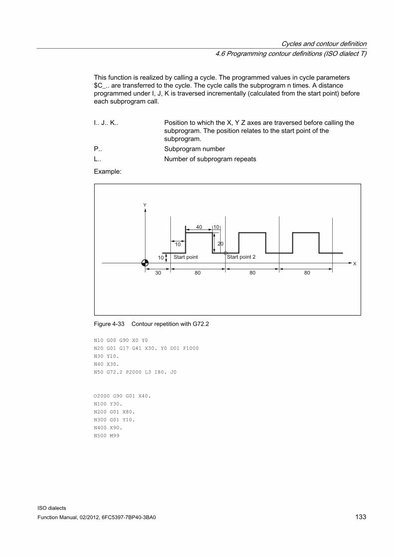
Cycles and contour definition 4.6 Programming contour definitions (ISO dialect T)
ISO dialects Function Manual, 02/2012, 6FC5397-7BP40-3BA0 133
This function is realized by calling a cycle. The programmed values in cycle parameters $C_.. are transferred to the cycle. The cycle calls the subprogram n times. A distance programmed under I, J, K is traversed incrementally (calculated from the start point) before each subprogram call.
I.. J.. K.. Position to which the X, Y Z axes are traversed before calling the
subprogram. The position relates to the start point of the subprogram.
P.. Subprogram number L.. Number of subprogram repeats
Example:
Figure 4-33 Contour repetition with G72.2
N10 G00 G90 X0 Y0
N20 G01 G17 G41 X30. Y0 D01 F1000
N30 Y10.
N40 X30.
N50 G72.2 P2000 L3 I80. J0
O2000 G90 G01 X40.
N100 Y30.
N200 G01 X80.
N300 G01 Y10.
N400 X90.
N500 M99

Cycles and contour definition 4.6 Programming contour definitions (ISO dialect T)
ISO dialects 134 Function Manual, 02/2012, 6FC5397-7BP40-3BA0
4.6.7 Output on an external device / an external file
Function With the "Process DataShare" function, it is possible to write data from a part program to an external device or an external file; for instance, e.g. to log production data or to control additional equipment on a control system.
The part program commands ISOOPEN, ISOPRINT and ISOCLOSE are provided for output on an external device in the ISO language mode. These commands are parameterized via the NCK machine data 10830 $MN_EXTERN_PRINT_DEVICE and 10831 $MN_EXTERN_PRINT_MODE.
The ISOOPEN, ISOPRINT and ISOCLOSE commands listed here may only be on their own in a program block – apart from the block number, skip identifier and comment.
In ISO mode, precisely one device can be used for the output across all channels.
ISOPEN (open output device) The output device referenced with MD $MN_EXTERN_PRINT_DEVICE is opened. MD $MN_EXTERN_PRINT_MODE bit 0 can be used to set whether the output is to be synchronous (FALSE) or asynchronous (TRUE), and $MN_EXTERN_PRINT_MODE bit 1 (FALSE) used to set whether the output device is to be assigned exclusively.
If MD $MN_EXTERN_PRINT_MODE bit 2 is set, the control character DC2 (H12) is output with ISOOPEN.
MD $MN_EXTERN_PRINT_MODE bits 4 and 5 can be used to determine whether the output is to be terminated with LF or CR+LF.
Alarm 14066 "Error during output on an external device" is issued when an error occurs and the part program execution is aborted. The error cause is specified in the alarm parameter "error code".
ISOPRINT (output on an external device) Syntax:
ISOPRINT[<Format string>, <Value list>]

Cycles and contour definition 4.6 Programming contour definitions (ISO dialect T)
ISO dialects Function Manual, 02/2012, 6FC5397-7BP40-3BA0 135
<Format string> Character string that contains fixed and variable parts. The variable parts
are specified by the format statement %P. Each %P is assigned a value from the <Value list> %.nP: Output of a binary value with n decimal places
Example: ISOPRINT("X%.3P", 123.456) %m.nP: Output of a decimal number with m places before the decimal
point and n decimal places. Example: ISOPRINT("X%5.3P", 123.456)
The <Format string> must only include format operations of one type (%.nP or %m.nP). The "*" character is converted to a blank. The start and end of the format string is identified by a ". Example: "Measured value part 1: %3.2P"
<Value list> List of the values to be output in the form of REAL constants. The individual values are separated by commas. The value list can contain a maximum of ten values.
The prepared string is output on the output device previously opened with ISOOPEN. The output is terminated with LF or CR+LF depending on the setting of MD $MN_EXTERN_PRINT_MODE, bits 4 and 5.
Alarm 14066 "Error during output on an external device" is issued when an error occurs during the output and the part program execution is aborted. The error cause is specified in the alarm parameter "error code".
ISOCLOSE (close output device) The output device opened with ISOOPEN is closed. If MD $MN_EXTERN_PRINT_MODE bit 3 is set, the control character DC4 (H14) is output with ISOCLOSE.

Cycles and contour definition 4.6 Programming contour definitions (ISO dialect T)
ISO dialects 136 Function Manual, 02/2012, 6FC5397-7BP40-3BA0
4.6.8 Convex thread with G35 and G36 In ISO dialect T, convex threads are programmed with G codes G35 in the clockwise direction and G36 in the counter-clockwise direction.
These G codes are available for the G code systems A, B and C. The arc can be programmed with specification of the circle center point via the circle parameters I, J, K or via specification of the radius R. Optionally, a thread starting point offset can be specified with Q. If R is programmed together with I, J, K, only R is effective.
Programming:
X.. Y.. Z.. I.. J.. K.. R.. F.. Q..
X Y Z End point of the arc I J K Coordinates for circle center point programming R Radius for radius programming F Lead in the direction of the main axis Q Thread starting point offset (optional)
Convex threads are described in detail in SINUMERIK 840D sl / 828D Fundamentals Programming Manual, Section 9 "Motion commands".

ISO dialects Function Manual, 02/2012, 6FC5397-7BP40-3BA0 137
Commissioning 55.1 Machine data
Activating ISO dialect mode MD18800 $MN_MM_EXTERN_LANGUAGE
Selection of ISO dialect M or T MD 10880 $MN_MM_EXTERN_CNC_SYSTEM=1: ISO dialect M
MD 10880 $MN_MM_EXTERN_CNC_SYSTEM=2: ISO dialect T
ISO dialect T axis names The maximum number of axes is eight. The axis identifiers of the first two axes are fixed X, Z. Possible axis identifiers for the other axes are Y, A, B, C, U, V, W.
If G code system A is active (there is then no G91), incremental values are programmed for X, Z, Y with U, V, W. U, V, W cannot then be used as axis identifiers, a maximum of six axes are possible. H is used to incrementally traverse the C axis.
If B is not used as an axis identifier, B can be used as an extended auxiliary function. B is then output as auxiliary function H with address extension 1 (H1=).
Contour definition:
MD20734 $MC_EXTERN_FUNCTION_MASK, bit 0 is used to define the programming for the contour definition.
0: Contour definition is programmed with ,C ,R ,A (with commas). C and A can be axis identifiers.
1: Contour definition is programmed with C R A (without commas). C and A cannot be axis identifiers.
ISO dialect M axis names The maximum number of axes is eight. The axis identifiers of the first three axes are fixed X, Y, Z. Possible axis names for the other axes are A, B, C, U, V, W.
If B is not an auxiliary function, B can be used as an axis identifier.
Axis interpolation All programmable axes interpolate with one another as standard with ISO dialect.
This corresponds to FGROUP with ISO dialect M: X, Y, Z (A, B, C, U, V, W). This corresponds to FGROUP with ISO dialect T: X, Z, Y (C).

Commissioning 5.1 Machine data
ISO dialects 138 Function Manual, 02/2012, 6FC5397-7BP40-3BA0
MD22420 $MC_FGROUP_DEFAULT_AXES[0] is used to achieve this behavior if the machine has four axes:
$MC_FGROUP_DEFAULT_AXES[0] = 1 $MC_FGROUP_DEFAULT_AXES[1] = 2 $MC_FGROUP_DEFAULT_AXES[2] = 3 $MC_FGROUP_DEFAULT_AXES[3] = 4
Work offset (ISO dialect M only) If only NVs G54 to G59 are used, MD28080 $MC_MM_NUM_USER_FRAMES or with global frames MD18601 $MC_MM_NUM_GLOBAL_USER_FRAMES >= 7 must be set.
If G54 is to be active after a reset, the following MD must be set to 1:
MD20154 $MC_EXTERN_GCODE_RESET_VALUES[13] MD20150 $MC_GCODE_RESET_VALUES[7]
If the extended work offsets G54 P1 to P48 are used, MD28080 $MC_MM_NUM_USER_FRAMES or with global frames MD18601 $MC_MM_NUM_GLOBAL_USER_FRAMES >= 55 must be set.
If the following MD is set to 7, after a reset, G54 P1 is active: MD 20154 $MC_EXTERN_GCODE_RESET_VALUES[13] MD 20150 $MC_GCODE_RESET_VALUES[7]
G54 P1 is mapped to Siemens G507.
If an activated work offset is not to be retracted with G91, the following setting data should be set to 0: SD 42440 $SC_FRAME_OFFSET_INCR_PROG
Suppress tool lengths and radius compensation with G53: MD 10760 $MN_G53_TOOLCORR = 1
Metric/Inch switchover The handwheel evaluation and increment evaluation are not switched over with G20 and G21. This switchover must be performed from the PLC: See MD31090 $MA_JOG_INCR_WEIGHT.
In ISO dialect mode, the work offsets are converted during the switchover. With ISO dialect original, the comma is simply moved.
Programming diameter or radius When MD20150 $MC_GCODE_RESET_VALUES[28] = 2, diameter programming is activated for the transverse axis.
Decimal point programming MD10884 $MN_EXTERN_FLOATINGPOINT_PROG is used to chose between Standard Notation and PocketcalculatorNotation.

Commissioning 5.1 Machine data
ISO dialects Function Manual, 02/2012, 6FC5397-7BP40-3BA0 139
Input resolution IS-B and IS-C is selected with MD10886 $MN_EXTERN_INCREMENT_SYSTEM.
Note that MD10200 $MN_INT_INCR_PER_MM and 10210 $MN_INT_INCR_PER_DEG are at least set such that input resolution IS-B or IS-C can be allocated.
If this is not the case, the programmed values are rounded.
Example: IS-C mm $MN_INT_INCR_PER_MM = 10000.
Scaling MD22910 $MC_WEIGHTING_FACTOR_FOR_SCALE=0: 0.001
MD22910 $MC_WEIGHTING_FACTOR_FOR_SCALE=1: 0.00001
Axial scaling factor: MD43120 $MA_DEFAULT_SCALE_FACTOR_AXIS
Scaling factor P: MD42140 $MC_DEFAULT_SCALE_FACTOR_P
Enable axial scaling: MD22914 $MC_AXES_SCALE_ENABLE = 1 (when = 0, axial scaling is not possible)
Position in machine coordinate system G53 The axial speed for positioning with G53 and with G00 without interpolation is defined in MD32060 $MA_POS_AX_VELO.
With G53 X.. Y... , a position in the machine coordinate system is approached. The axes don't interpolate with one another, instead each axis moves to the programmed position separately at maximum speed.
Incremental positions are skipped in the G53 block. While tool radius compensation or tool length compensation is active (G41/G42, G43/G44), the axes are not traversed independently of one another, the axes are interpolated with one another.
Setting actual value G92 Delete the G92 movement at PowerOn: MD24004 $MC_CHBFRAME_POWERON_MASK=1
G92 is retained during a reset (M30, channel reset): MD20110 $MC_RESET_MODE_MASK bit 0 and bit 14=1

Commissioning 5.1 Machine data
ISO dialects 140 Function Manual, 02/2012, 6FC5397-7BP40-3BA0
Resetting the tool coordinate system G92.1 With G92.1 X.. (G code system A: G50.3 P0), a moved coordinate system can be reset before being moved. The tool coordinate system is reset to the coordinate system that is defined by the active adjustable work offsets (G54-G59). The tool coordinate system is set to the reference position if no adjustable work offset is active. G92.1 resets shifts carried out through G92 or G52. However, only the axes that are programmed are reset.
Example 1:
N10 G0 X100 Y100 ;Display: WCS: X100 Y100 MCS: X100 Y100 N20 G92 X10 Y10 ;Display: WCS: X10 Y10 MCS: X100 Y100 N30 G0 X50 Y50 ;Display: WCS: X50 Y50 MCS: X140 Y140 N40 G92.1 X0 Y0 ;Display: WCS: X140 Y140 MCS: X140 Y140
Example 2:
N10 G10 L2 P1 X10 Y10 N20 G0 X100 Y100 ;Display: WCS: X100 Y100 MCS: X100 Y100 N30 G54 X100 Y100 ;Display: WCS: X100 Y100 MCS: X110 Y110 N40 G92 X50 Y50 ;Display: WCS: X50 Y50 MCS: X110 Y110 N50 G0 X100 Y100 ;Display: WCS: X100 Y100 MCS: X160 Y160 N60 G92.1 X0 Y0 ;Display: WCS: X150 Y150 MCS: X160 Y160
Delete distance-to-go With ISO dialect original, G31 can be used to delete the distance-to-go. The distance-to-go is only deleted in this block if the PLC signal is in place for the channel. Without G31, the signal is not evaluated.
In ISO dialect mode, the PLC signals are evaluated in each block regardless of G31. G31 is used to activate probe 1.
With ISO dialect, the deleted distance-to-go can be calculated using PLC Varselector.
The function G31 P1 (.. P4) is different from G31 in that different inputs for the measuring signal can be selected with P1-P4. Several inputs can also be monitored on a rising edge of a measuring signal simultaneously. The assignment of the inputs to the addresses P1 to P4 is defined by the following machine data.
MD10810 $MN_EXTERN_MEAS_G31_P_SIGNAL[0 .. 3].
Note
Only two measuring inputs are available for the 840D sl.

Commissioning 5.1 Machine data
ISO dialects Function Manual, 02/2012, 6FC5397-7BP40-3BA0 141
Spindle position The spindle position for M19 is set using setting data 43240 $SC_M19_SPOS.
Protection zone If G commands G22 and G23 are used, there must be a protection zone:
MD18190 $MM_NUM_PROTECT_AREA_NCK = 1 MD28210 $MC_NUM_PROTECT_AREA_ACTIVE = 1
Auxiliary function output If value H is to be output to the PLC as an integer value, MD22110 $MC_AUXFU_H_TYPE_INT must be set to 1.
The time at which the auxiliary function is output (M, S, T, H) to the PLC can be set using machine data:
0 = Auxiliary function output before motion
1 = Auxiliary function output during motion
2 = Auxiliary function output after motion
3 = Motion is not output to PLC
MD22200 $MC_AUXFU_M_SYNC_TYPE for M functions MD22210 $MC_AUXFU_S_SYNC_TYPE for S functions MD22220 $MC_AUXFU_T_SYNC_TYPE for T functions MD22230 $MC_AUXFU_H_SYNC_TYPE for H functions
Approach 1st reference point G28 The following machine data must be set:
● 20050 $MC_AXCONF_GEOAX_ASSIGN_TAB[0-2]
Axis 1 to 3
● 20060 $MC_AXCONF_GEOAX_NAME_TAB[0-2]
Axis names for milling: X, Y, Z Axis names for turning: X, Z, Y
● 200070 $MC_AXCONF_MACHAX_USED[0-3]
Axis 1 to 4
● 20080 $MC_AXCONF_CHANAX_NAME_TAB[0-3]
4th axis name for milling: X, Y, Z are permanently assigned; A, B, C, U, V or W can also be selected. 4th axis name for turning: X, Z, Y are permanently assigned; C can also be selected
● 20100 $MC_DIAMETER_AX_DEF
Only when turning: X axis

Commissioning 5.1 Machine data
ISO dialects 142 Function Manual, 02/2012, 6FC5397-7BP40-3BA0
● 20150 $MC_GCODE_RESET_VALUES[28]
Radius or diameter programming
1 = DIAMOF (radius for G90/G91)
2 = DIAMON (diameter for G90/G91)
3 = DIAM90 (diameter for G90, radius for G91)
Note: DIAM90 is treated like DIAMON within the cycle.
● 34100 $MA_REFP_SET_POS[0]
0 = 1st reference point
Enter a value for each axis
● 35000 $MA_SPIND_ASSIGN_TO_MACHAX
0 = Axis is not spindle
1 = Axis is a spindle
Approach 2nd/3rd/4th reference point G30 The following machine data must be set:
● 20050 $MC_AXCONF_GEOAX_ASSIGN_TAB[0-2]
Axis 1 to 3
● 20060 $MC_AXCONF_GEOAX_NAME_TAB[0-2]
Axis names for milling: X, Y, Z
Axis names for turning: X, Z, Y
● 20070 $MC_AXCONF_MACHAX_USED[0-3]
Axis 1 to 4
● 20080 $MC_AXCONF_CHANAX_NAME_TAB[0-3]
4th axis name for milling: X, Y, Z are permanently assigned; A, B, C, U, V or W can also be selected.
4th axis name for turning: X, Z, Y are permanently assigned; C can also be selected
● 20100 $MC_DIAMETER_AX_DEF
Only when turning: X axis
● 20150 $MC_GCODE_RESET_VALUES[28]
Radius or diameter programming
1 = DIAMOF (radius for G90/G91)
2 = DIAMON (diameter for G90/G91)
3 = DIAM90 (diameter for G90, radius for G91)
Note: DIAM90 is treated like DIAMON within the cycle.
Commissioning 5.1 Machine data
ISO dialects Function Manual, 02/2012, 6FC5397-7BP40-3BA0 143
● 34100 $MA_REFP_SET_POS[1,2,3]
1,2,3 = 2nd, 3rd, 4th reference point
Enter a value for each axis
● 35000 $MA_SPIND_ASSIGN_TO_MACHAX
0 = Axis is not spindle
1 = Axis is a spindle
G30.1 reference point position Reference point approach is realized in the CYCLE328 cycle. The reference point position is written in setting data 43340 $SC_EXTERN_REF_POSITION_G30_1.
5.1.1 Active G command for PLC The user can use MD22512 $MC_EXTERN_GCODE_GROUPS_TO_PLC to select the G groups of an external language whose active G command is to be reported to the PLC.
$MC_EXTERN_GCODE_GROUPS_TO_PLC[0..7]=0
5.1.2 Tool change, tool data No cutting edge is selected during a tool change.
MD20270 $MC_CUTTING_EDGE_DEFAULT = 0
Setting datum: During a tool change, with G91 the compensation is not retracted
SD42442 $SC_TOOL_OFFSET_INCR_PROG = 0
The assignment of tool length compensation to geometry axes is fixed:
Length 1: Z Length 2: Y Length 3: X
SD42940 $SC_TOOL_LENGTH_CONST =17
Effectiveness of tool length compensation beyond reset:
MD20110 $MC_RESET_MODE_MASK = 'B1000000'
Effectiveness of tool compensation with programming of T/H/D, not with M6
MD22550 $MC_TOOL_CHANGE_MODE = 0

Commissioning 5.1 Machine data
ISO dialects 144 Function Manual, 02/2012, 6FC5397-7BP40-3BA0
5.1.3 G00 always with exact stop At high speeds, collisions may occur during active continuous-path mode in G00 mode when smoothing. MD20734 $MC_EXTERN_FUNCTION_MASK, bit 4 is used to determine the exact stop behavior with G00.
MD20734 $MC_EXTERN_FUNCTION_MASK, bit 4=0, G00 is traversed with the exact stop function currently active. If G64 is active, the G00 blocks are also traversed with G64.
MD20734 $MC_EXTERN_FUNCTION_MASK, bit 4=1, each G00 block with traversing is traversed with G09 (non-modal exact stop). Even if G64 is active, the non-modal exact stop takes effect in every G00 block.
5.1.4 Response to syntax faults
Response to faults occurring MD20734 $MC_EXTERN_FUNCTION_MASK, bit 3 is used to determine the response to faults occurring in the first part of the ISO Translator. Here the entire ASCII block is examined.
If bit 3==0, an NC alarm is output and processing is stopped if unknown addresses are found.
If bit 3==1, no alarm is output, the ASCII block is forwarded to the Siemens Translator. The NC block following this is first given back to the ISO Translator and an attempt is made in the Siemens Translator to translate the ASCII block.
This allows unique Siemens blocks to be programmed without using G290 to switch to Siemens mode while ISO mode is active.
The current ISO G code is displayed in the G code window, a switch is not made to Siemens mode.
If a G function, which can be translated directly to an ISO G code, is activated in such a block in the Siemens Translator, the G codes are updated here.
Example 20734 $MC_EXTERN_FUNCTION_MASK, bit 3==0 N5 G291 ;ISO mode
N10 WAIT ;Alarm 12080 "WAIT unknown"
N15 G91 G500 ;Alarm 12080 "G500 unknown"
20734 $MC_EXTERN_FUNCTION_MASK, bit 3==1 N5 G291 ;ISO mode
N10 WAIT ;block is processed by the Siemens Translator
N15 G91 G500 ;block is processed by the Siemens Translator
N20 X Y ;because of G291, block is processed by ISO Translator,;G91 from N15 is active

Commissioning 5.1 Machine data
ISO dialects Function Manual, 02/2012, 6FC5397-7BP40-3BA0 145
Note
Unwanted responses may result from incorrect programming in ISO mode.
Example for ISO M:
To be programmed: G90 G76 ;modal cycle call
but the following is entered: G90 G75
G75 is not available in ISO M mode, the block goes to the Siemens Translator and results in "Move to fixed point" without any query or alarm G75.
5.1.5 Selection of code system A, B, C (ISO dialect T)
Function In ISO dialect-T, a differentiation is made between G code system A, B and C. By default, the G code system B is active.
Code system A, B or C is selected in MD10881 $MN_MM_EXTERN_GCODE_SYSTEM. The "Rename G codes" function is not used by this function, the user can use this function without any limitations.
As previously, switching over with a cycle is still possible.
$MN_MM_EXTERN_CNC_SYSTEM = 1: ISO dialect M $MN_MM_EXTERN_CNC_SYSTEM = 2: ISO dialect T
$MN_MM_EXTERN_GCODE_SYSTEM = 0: G code system B
$MN_MM_EXTERN_GCODE_SYSTEM = 1: G code system A
$MN_MM_EXTERN_GCODE_SYSTEM = 2: G code system C
In order for the shell cycle to work in the correct G code system, the corresponding system must be entered in the GUD variable _ZSFI[39]:
_ZSFI[39]: Setting datum for G code system with ISO T
0 = G code system B 1 = G code system A 2 = G code system B 3 = G code system C

Commissioning 5.1 Machine data
ISO dialects 146 Function Manual, 02/2012, 6FC5397-7BP40-3BA0
Inch/metric changeover With ISO dialect original there is a MD which is used to determine how the inch/metric changeover is programmed, either with G20/21 or G70/71. This MD does not exist for ISO dialect mode, it can also not be selected using $MN_MM_EXTERN_GCODE_SYSTEM.
G20/G21 is active by default. A switchover to G70/71 is realized using MD10712 $MN_USER_CODE_CONF_NAME_TAB. $MN_USER_CODE_CONF_NAME_TAB[0]= G20 $MN_USER_CODE_CONF_NAME_TAB[1]= G70 $MN_USER_CODE_CONF_NAME_TAB[2]= G21 $MN_USER_CODE_CONF_NAME_TAB[3]= G71
Regardless of G20/21 G70/71, a 1 is read in system variable $P_GG[6] with G20/G70 and a 2 with G21/G71.
5.1.6 Fixed feedrates F0 - F9
Function Ten different feedrate values pre-set via setting data can be activated with F0-F9.
To activate the rapid traverse rate with F0, the corresponding speed must be entered in the setting datum 42160 $SC_EXTERN_FIXED_FEEDRATE_F1_9[0].
The feedrate values for F0-F9 are entered in the setting data as real values. An evaluation of the input values is not undertaken.
The function is activated via MD22920 $MC_EXTERN_FIXED_FEEDRATE_F1_ON. If the machine data is set to FALSE, F1-F9 is interpreted as normal feedrate programming, e.g. F2=2 mm/min, F0=0 mm/min.
If the machine data = TRUE, the feedrate values for F0-F9 are fetched from the setting data 42160 $SC_EXTERN_FIXED_FEEDRATE_F1_F9[ ]. If the value 0 exists in one of the setting data, then the corresponding address extension of feedrate 0 is activated during the programming.

Commissioning 5.1 Machine data
ISO dialects Function Manual, 02/2012, 6FC5397-7BP40-3BA0 147
Example $SC_FIXED_FEEDRATE_F1_F9[0] = 5000 $SC_FIXED_FEEDRATE_F1_F9[1] = 1000 $SC_FIXED_FEEDRATE_F1_F9[2] = 500
N10 X10 Y10 Z10 F0 G94 ;Approach position at 5000 mm/min
N20 G01 X150 Y30 F1 ;Feedrate 1000 mm/min active
N30 Z0 F2 ;Position approached at 500 mm/min
N40 Z10 F0 ;Approach position at 5000 mm/min
If the function is activated with MD22920 $MC_FIXED_FEEDRATE_F1_F9_ON and if the feedrate value from the setting datum is not to be active with F1-F9, then the feedrate value is programmed as a real value. If, for instance, a feedrate value should be programmed at 1 mm/min, the feedrate must be programmed with F1.0 instead of F1.
Note
While macroprogramming with G65/66, the programmed value for the address F is always entered in the $C_F system variable. The address signifies a transfer variable here and has no direct reference to the feedrate.
The same is true of the thread lead programming in G33-G34 with address F. No feedrate is programmed with F here, instead the distance between 2 threads during a spindle revolution.
In cycle programming (e.g., G81 X.. Y.. Z.. R.. P.. Q.. F..), the feedrate is always programmed under address F. In a part program block with a cycle call via a G function (G81-G87 etc.), the corresponding feedrate value during the programming of F1-F9 is written from the corresponding setting datum in the variable $C_F.
Restriction In ISO dialect mode, the feedrate values are changed in the setting data with a handwheel. In Siemens mode, the feedrates can be influenced only like a directly programmed feedrate, e.g. using the override switch.

Commissioning 5.1 Machine data
ISO dialects 148 Function Manual, 02/2012, 6FC5397-7BP40-3BA0
5.1.7 Parallel axes G17 (G18/G19)<Axis name>.. Function G17 (G18, G19)<Axis name>.. can be used to activate an axis parallel to the basic axis in the coordinate system.
The basic axes are, e.g. X, Y and Z. The following programming is used to activate axis U in the G17 plane in place of basic axis X:
G17 U0 Y0 ;Activation of parallel axis U
This function can be reproduced with the 840D sl function GEOAX (..,..). GEOAX() can be used to replace a geometry axis with any channel axis. But all frames (apart from handwheel and external movement), the working area limitation and the protection zones are then deleted. The user can prevent the frames from being deleted with MD10602 $MN_FRAME_GEOAX_CHANGE_MODE, the protection zones from being deleted with MD10618 $MC_PROTAREA_GEOAX_CHANGE_MODE and working area limitation from being deactivated with MD10604 $MN_WALIM_GEOAX_CHANGE_MODE.
One parallel axis can be defined for each of the three geometry axes using MD22930 $MC_EXTERN_PARALLEL_GEOAX[ ]. By programming the G function for plane selection (G17-G19) and the axis name of the parallel axis, a geometry axis interchange is then carried out as with the GEOAX() function.
During the selection of planes (geometry axis interchange with parallel axis), the axes are moved to their programmed position.
If a basic axis of the coordinate system is programmed along with its parallel axis in a plane selection block, alarm 12726 "Impermissible plane selection with parallel axes" is output.
5.1.8 Inserting chamfers and radii
Chamfers and radii The process of inserting chamfers and radii is mapped to the corresponding Siemens functionality. The two blocks between which a radius or chamfer is to be inserted must always be programmed. If there are several addresses programmed in a block, the last radius programmed always takes effect.
In ISO dialect M mode, the name for the radius is always "R" and for the chamfer "C". As soon as a comma is programmed in the block, addresses R and C to the right after the comma are interpreted as radius and chamfer. If a circle is to be programmed with radius R or axis C, the two addresses must be positioned to the left before the comma. A radius or chamfer can be inserted between linear blocks, circle blocks or a mix of the two.
In ISO dialect T mode, the name for the radius is always "R", while addresses "C", "I" and "K" can be used for the chamfer. Address C may only be used if it is not defined as an axis name. Radii and chamfers can only be inserted between linear blocks. The linear blocks do not have to be above one another vertically. Programming a sign before the chamfer and/or radius is of no significance here because the direction of the chamfer and/or radius is defined with the 2nd straight line block.

Commissioning 5.1 Machine data
ISO dialects Function Manual, 02/2012, 6FC5397-7BP40-3BA0 149
ISO dialect M programming Chamfers and radii are always marked in the block with a comma. The address for a chamfer is "C" and for a radius is "R". Chamfers and radii can be inserted between linear blocks and circle blocks.
N10 X100. ,R10 ;insert radius of 10 mm
N20 Y30. ,C5 ;insert chamfer of 5 mm
N30 X150. Y40.
N40 G03 X180. Y65. R30, R8
N50 G01 X150. ,R8
ISO dialect T programming Chamfers and radii are not marked in the block with a comma. The address for a radius is always "R", address "I", "K" or "C" can be used for a chamfer. C may only be used if the address is not defined as an axis name.
In ISO dialect T mode, chamfers and radii can only be inserted between 2 linear blocks.
N10 X100. R10 ;insert radius of 10 mm
N20 Z30. C5 ;insert chamfer of 5 mm
N30 X150. Z40.
N40 X180. Z65. I8
N50 G01 X150. K8
5.1.9 Rotary axis function If an axis is defined as a rotary axis, this axis can be traversed as follows:
● Axis is traversed as linear axis
No modulo conversion is active.
Positive and negative values can be programmed
MD30300 $MA_IS_ROT_AX = TRUE
MD30310 $MA_ROT_IS_MODULO = FALSE
● Example:
N5 G90 B0
N10 B370 ;axis moves to 370 degrees
N15 B-10 ;axis moves to -10 degrees
N20 G91 B-20 ;axis moves to -20 degrees
Commissioning 5.1 Machine data
ISO dialects 150 Function Manual, 02/2012, 6FC5397-7BP40-3BA0
● Axis traverses at shortest distance
Modulo conversion is active
Values < 0 and > modulo value can be programmed
MD30300 $MA_IS_ROT_AX = TRUE
MD30310 $MA_ROT_IS_MODULO = TRUE
MD20734 $MC_EXTERN_FUNCTION_MASK, bit 5 = 0
MD30455 $MA_MISC_FUNCTION_MASK, bit 0 = 1
Example:
N5 B0 ;axis moves to 0 degrees
N10 B10 ;axis moves to 10 degrees, positive
;Direction of rotation
N15 B350 ;axis moves to 350 degrees, negative
;Direction of rotation
N20 B-5 ;axis moves to 355 degrees, positive
;Direction of rotation
N25 G91 B-10 ;axis moves to 345 degrees, negative
;Direction of rotation
● Axis traverses in positive or negative direction depending on sign programmed
Modulo conversion is active
Values < 0 and > modulo value can be programmed
MD30300 $MA_IS_ROT_AX = TRUE
MD30310 $MA_ROT_IS_MODULO = TRUE
MD20734 $MC_EXTERN_FUNCTION_MASK, bit 5 = 1
MD30455 $MA_MISC_FUNCTION_MASK, bit 0 = 1
Example:
N5 B0 ;axis moves to 0 degrees
N10 B10 ;axis moves to 10 degrees, ;positive direction of rotation
N15 B350 ;axis moves to 350 degrees, ;positive direction of rotation
N20 B-5 ;axis moves to 355 degrees, ;negative direction of rotation
N25 G91 B-10 ;axis moves to 345 degrees, ;negative direction of rotation
In this case, the sign has two meanings, it is taken into account in the modulo conversion and determines the direction of rotation.
The response is the same for all types of interpolation.
Incremental motion is always executed depending on the sign.

Commissioning 5.1 Machine data
ISO dialects Function Manual, 02/2012, 6FC5397-7BP40-3BA0 151
5.1.10 Program coordination between 2 channels and M commands
Overview M functions which serve as WAIT marks can be programmed to synchronize the program sequence between two channels. If one such M function is reached in the part program of one channel, the program sequence is stopped until the other channel has also reached the same M function. The part programs in the two channels are then processed further.
The M function numbers for the Wait marks are defined with two pieces of machine data. A range of M numbers is defined and reserved for this function.
Machine data 10800 $MN_EXTERN_CHAN_SYNC_M_NO_MIN marks the smallest M number and 10802 $MN_EXTERN_CHAN_SYNC_M_NO_MAX the largest M number in the range reserved for program coordination. Machine data $MN_EXTERN_CHAN_SYNC_M_NO_MAX must not exceed ($MN_EXTERN_CHAN_SYNC_M_NO_MIN + 10 * number of channels).
To avoid conflicts with standard M functions, the smallest M number (MD $MN_EXTERN_CHAN_SYNC_M_NO_MIN) must not be less than 100. If the machine data is predefined with -1, this means that program coordination in ISO dialect T/M mode is not possible.
If a value <100 is entered in $MN_EXTERN_CHAN_SYNC_M_NO_MIN or a value <$MN_ETERN_CHAN_SYNC_M_NO_MIN is entered in $MN_EXTERN_CHAN_SYNC_M_NO_MAX, alarm 4170 "Impermissible number for channel synchronization" is output.
The function is mapped to the WAITM command of the Siemens language (WAITM(<mark>, <channel number>, <channel number>)). Channel synchronization in ISO dialect T/M mode is always carried out for channels 1 and 2. All other channels can only be synchronized in Siemens mode.
The M numbers are not output to the PLC.
The M functions for channel synchronization must be the only items in their block. The system issues alarm 12080 "Channel %1 block %2 syntax error for text" if addresses other than "M" are programmed in the block.
For a more detailed description, see
Job Planning; Section "Program coordination"
Constraint Only 10 M functions (WAIT marks) can be set per channel. The difference between $MN_EXTERN_CHAN_SYNC_M_NO_MAX and $MN_EXTERN_CHAN_SYNC_M_NO_MIN must therefore not exceed 20 in a 2-channel system. With ISO dialect original 99999899 M numbers can be defined as wait marks.
Commissioning 5.2 Standard machine data assignment for ISO dialect
ISO dialects 152 Function Manual, 02/2012, 6FC5397-7BP40-3BA0
5.2 Standard machine data assignment for ISO dialect
ISO dialect M Standard assignment of MD20154 $MC_EXTERN_GCODE_RESET_VALUES[ ]:
$MC_EXTERN_GCODE_RESET_VALUES[0] = 1 G00 $MC_EXTERN_GCODE_RESET_VALUES[1]=1 G17 $MC_EXTERN_GCODE_RESET_VALUES[2]=1 G90 $MC_EXTERN_GCODE_RESET_VALUES[3]=2 G23 $MC_EXTERN_GCODE_RESET_VALUES[4]=1 G94 $MC_EXTERN_GCODE_RESET_VALUES[5]=1 G20 $MC_EXTERN_GCODE_RESET_VALUES[6]=1 G40 $MC_EXTERN_GCODE_RESET_VALUES[7]=3 G49 $MC_EXTERN_GCODE_RESET_VALUES[8]=4 G80 $MC_EXTERN_GCODE_RESET_VALUES[9]=1 G98 $MC_EXTERN_GCODE_RESET_VALUES[10]=1 G50 $MC_EXTERN_GCODE_RESET_VALUES[11]=2 G67 $MC_EXTERN_GCODE_RESET_VALUES[12]=2 G97 $MC_EXTERN_GCODE_RESET_VALUES[13]=1 G54 $MC_EXTERN_GCODE_RESET_VALUES[14]=3 G64 $MC_EXTERN_GCODE_RESET_VALUES[15]=2 G69 $MC_EXTERN_GCODE_RESET_VALUES[16]=1 G15 $MC_EXTERN_GCODE_RESET_VALUES[17]=0 non-modal $MC_EXTERN_GCODE_RESET_VALUES[21]=1 G50.1 $MC_EXTERN_GCODE_RESET_VALUES[24]=1 G12.1 $MC_EXTERN_GCODE_RESET_VALUES[30]=1 G290

Commissioning 5.2 Standard machine data assignment for ISO dialect
ISO dialects Function Manual, 02/2012, 6FC5397-7BP40-3BA0 153
ISO dialect T Standard assignment of MD20154 $MC_EXTERN_GCODE_RESET_VALUES[ ]:
Several G code systems are available as options for ISO dialect T. The same function is called using different G commands. G code system B is realized as standard. Machine datum 10881 $MN_ EXTERN_GCODE_SYSTEM is used to use another G code system.
$MC_EXTERN_GCODE_RESET_VALUES[0]=1 G00 $MC_EXTERN_GCODE_RESET_VALUES[1]=2 G97 $MC_EXTERN_GCODE_RESET_VALUES[2]=1 G90 $MC_EXTERN_GCODE_RESET_VALUES[3]=2 G69 $MC_EXTERN_GCODE_RESET_VALUES[4]=2 G95 $MC_EXTERN_GCODE_RESET_VALUES[5]=1 G21 $MC_EXTERN_GCODE_RESET_VALUES[6]=1 G40 $MC_EXTERN_GCODE_RESET_VALUES[8]=2 G23 $MC_EXTERN_GCODE_RESET_VALUES[9]=1 G80 $MC_EXTERN_GCODE_RESET_VALUES[10]=1 G98 $MC_EXTERN_GCODE_RESET_VALUES[11]=2 G67 $MC_EXTERN_GCODE_RESET_VALUES[15]=2 G18 $MC_EXTERN_GCODE_RESET_VALUES[17]=0 non-modal $MC_EXTERN_GCODE_RESET_VALUES[19]=1 G50.2 $MC_EXTERN_GCODE_RESET_VALUES[20]=1 G12.1 $MC_EXTERN_GCODE_RESET_VALUES[30]=1 G290

Commissioning 5.2 Standard machine data assignment for ISO dialect
ISO dialects 154 Function Manual, 02/2012, 6FC5397-7BP40-3BA0

ISO dialects Function Manual, 02/2012, 6FC5397-7BP40-3BA0 155
Supplementary conditions 66.1 Supplementary conditions
Availability of the "ISO dialect" function The function is standard for the SINUMERIK 840Dsl and 828D.

Supplementary conditions 6.2 Constraints
ISO dialects 156 Function Manual, 02/2012, 6FC5397-7BP40-3BA0
6.2 Constraints The functions with which non-compatible behavior towards ISO dialect original occurs in the SINUMERIK 840D sl ISO dialect mode are listed below.
Mode switchover The standard machine data block only realizes "Siemens" mode. No external NC language is generated as the 2nd G code table.
Machine data $MN_NC_USER_CODE_CONF_NAME_TAB is only valid for NC language commands in Siemens mode.
For reasons associated with compatibility with Siemens mode (relating to machine data input, BTSS interface "data field"[0] = 1st G group), in ISO dialect mode, the G groups 0 defined in the ISO dialect original system are implemented:
ISO dialect M: G group 0 → G group 18
ISO dialect T: G group 0 → G group 17
Implied mode change Asubs, INI files and macro/GUD definition files are always processed in Siemens mode. If necessary, an implicit mode change to Siemens mode is undertaken here. At the end of processing, a switch is made back to the external CNC system's original mode.

Supplementary conditions 6.2 Constraints
ISO dialects Function Manual, 02/2012, 6FC5397-7BP40-3BA0 157
6.2.1 Program commands
F value ISO dialect M has fixed F values which are selected using F1 to F9. These fixed values are not available in ISO dialect mode. F1 to F9 is interpreted as values F1 to F9.
G02/G03 G02/G03 programming without radius details in ISO dialect T original results in G01, in ISO dialect M original it results in a complete circle with an undefined radius. In ISO dialect mode, an NC alarm is output in both cases.
G04 X.. With ISO dialect original, the dwell time is displayed in the X axis as distance-to-go. This dwell time is not displayed in ISO dialect mode, the "Dwell time running" message appears.
G16 Polar coordinate programming is ended with G15.
With ISO dialect original, the pole radius and pole angle are retained. When G16 is next programmed, incremental additions can be made to the angle. Non-reproducible traversing is undertaken. The angle and radius are deleted using a reset or M30.
In ISO dialect mode, G15 is used to delete the pole radius and pole angle. G16 always results in an angle and radius of 0 being traversed.
Example: Axis U is parallel to axis X
G17 U Y ; plane U Y is selected rather than plane X Y.
In ISO dialect mode, a parallel axis cannot be programmed with G17/G18/G19.
G20/G21 In ISO dialect original mode, the work offsets are not converted during the switchover. The comma is simply moved by one decade. The work offset values are converted in full in ISO dialect mode.
G22 In ISO dialect M original, G22 is used to activate protection zone 4. This does not exist in step 1. Protection zones 1/2 and 3 are realized. Protection zone 4 is permanently entered in ISO dialect using machine data. This is not possible with the 840D sl. There is only one protection zone in ISO dialect mode.

Supplementary conditions 6.2 Constraints
ISO dialects 158 Function Manual, 02/2012, 6FC5397-7BP40-3BA0
G40 In ISO dialect T mode, a vector which influences the response at the block end can be programmed in the linear block with I, J, K. This function is not available in ISO dialect original mode. If I, J and K is programmed for G40, an NC alarm is output.
G41/G42 The milling radius compensation functions are not compatible between ISO dialect original and 840D sl.
G53 If G53 (approach position in machine coordinate system) is called while G41/G42 is active, the axes are not traversed separately but in an interpolating manner.
G63 With ISO dialect, G63 can be written in every block. The override is locked in this block. Override 0 also results in a stop at the start of a G53 block. This function is helpful when used in conjunction with tapping without floating tapholder in a G01 interpolation. In ISO dialect mode, G63 is only effective in a G01 block. If G63 is selected in a G00 block, this has no impact on this block.
G94/G95 If a change is made from revolutional feedrate (G95) to linear feedrate (G94) or vice versa, feedrate F has to be reprogrammed each time. If there is no feedrate, this results in alarm 10860 "No feedrate programmed". When changing the type of feedrate, ISO dialect original mode interprets the feedrate programmed either as revolutional or linear feedrate.
M06 Tool change cycle: If MD10715 $MN_M_NO_FCT_CYCLE and 10716 $MN_M_NO_FCT_CYCLE_NAME are used to assign a cycle to an M function, not all the parameters programmed in the block can be accessed in the cycle. Only the programmed tool number can be read with $C_T/$C_T_PROG. Traversing in the M block is retracted before the call.
G functions that define the syntax With ISO dialect original several G commands that define syntax can be programmed in a block. A distinction is made as to:
● Defining syntax → non-modal
● Defining syntax → modal
● Non-syntax → modal
● Non-syntax → non-modal
In Siemens mode, more than one G function that defines syntax in a block will result in an alarm.

Supplementary conditions 6.2 Constraints
ISO dialects Function Manual, 02/2012, 6FC5397-7BP40-3BA0 159
6.2.2 Tool management Tool management and service life and quantity monitoring can be reproduced with the Siemens tool management function.
Tool data Milling: Only tool compensation memory C is supported, i.e. the tool compensation memory is spread over several columns (D == H applies).
The version where the tool and compensation number for milling are produced from the same value is not supported.
The current tool data cannot be read out/archived in ISO dialect mode (G10). The tool data can only be changed via G10 if the tool compensation has been set up via operator input.
Tool length compensation If the tool length compensation input in the diameter is active, the input for geometry and wear in the diameter can be parameterized with ISO dialect original. Only wear in the diameter is stated in ISO dialect mode. The geometry is always stated in the radius.
With ISO dialect original, the tool length is calculated as diameter or radius in the transverse axis depending on a machine parameter.
In Siemens mode the tool length compensation is always calculated as diameter; a switchover is not possible.
The tool length compensation cannot be undertaken by moving the coordinate system.
Geometry and wear cannot be taken from different compensation memories for turning technology.
Modified tool compensations take effect when the next T, H or D value is programmed.

Supplementary conditions 6.2 Constraints
ISO dialects 160 Function Manual, 02/2012, 6FC5397-7BP40-3BA0
6.2.3 Control response with power on, reset and block search
Power on During power on, the Siemens G code list containing possible recoding from MD10712 $MN_NC_USER_CODE_CONF_NAME_TAB is created for all NC channels.
Power up, reset The power up and reset response is defined using MD 20150 $MC_GCODE_RESET_VALUES[46] and depending on MD10880 $MN_MM_EXTERN_CNC_SYSTEM.
This decides between the G codes of ISO dialect M and ISO dialect T.
Switching between Siemens and ISO dialect mode in the program sequence has no impact on the modal G functions.
Block search The "Search for block end point" block search type available in Siemens mode corresponds to the block search response in ISO dialect.
When in the "Block search without calculations" operating mode, the user must ensure a sensible search destination, especially for NC programs with a mode switchover (e.g. NC block with command from G group 47).

ISO dialects Function Manual, 02/2012, 6FC5397-7BP40-3BA0 161
Data descriptions (MD, SD) 77.1 General NC machine data
Note
All the machine data described here relates to the SINUMERIK 840D sl. Please use the associated List Manuals for the SINUMERIK 828D controls.
Table 7- 1
10604 WALIM_GEOAX_CHANGE_MODE MD number Working area limitation during switchover of geometry axes Default setting: 0 Min. input limit: 0 Max. input limit: 1 Changes effective after Power On Protection level: 7/2 Unit: - Data type: BYTE Meaning: This machine data defines whether a possibly active working area limitation is retained or
deactivated during a geometry axis interchange. The machine data values have the following meanings: Bit 0=0: Working field limitation is deactivated during geometry axis interchange Bit 0=1: Active working area limitation remains active during geometry axis interchange
10615 NCBFRAME_POWERON_MASK MD number Reset global basic frames after power on Default setting: 0 Min. input limit: 0 Max. input limit: 0xFFFF Changes effective after Power On Protection level: 7/2 Unit: - Data type: DWORD Meaning: This machine data is used to define whether global basic frames are reset in the data
management during power on. That is - offsets are set to 0. - scaling is set to 1. - mirroring is switched off. The individual basic frames can be selected separately. Bit 0 corresponds to basic frame 0, bit 1 to basic frame 1, etc. Value 0: Basic frame is retained at Power On Value 1: Basic frame is reset in the data management at Power ON.
Corresponds to: MD24004 CHBFRAME_POWERON_MASK

Data descriptions (MD, SD) 7.1 General NC machine data
ISO dialects 162 Function Manual, 02/2012, 6FC5397-7BP40-3BA0
10652 CONTOUR_DEF_ANGLE_NAME MD number Name of angle for contour definitions Default setting: "ANG" Min. input limit: - Max. input limit: - Changes effective after Power On Protection level: 0/0 Unit: - Data type: STRING Meaning: Identifier for contour angle.
The identifier must be selected ensuring that there is no conflict with other identifiers (e.g. axes, Euler angle, normal vector, direction vector, coordinate of intermediate point).
10654 RADIUS_NAME MD number Name of radius for contour definitions Default setting: "RND" Min. input limit: - Max. input limit: - Changes effective after Power On Protection level: 0/0 Unit: - Data type: STRING Meaning: Identifier for contour definition radius.
The identifier must be selected ensuring that there is no conflict with other identifiers (e.g. axes, Euler angle, normal vector, direction vector, coordinate of intermediate point).
10656 CHAMFER_NAME MD number Name of chamfer for contour definitions Default setting: "CHR" Min. input limit: - Max. input limit: - Changes effective after Power On Protection level: 0/0 Unit: - Data type: STRING Meaning: Identifier for contour definition chamfer
The identifier must be selected ensuring that there is no conflict with other identifiers (e.g. axes, Euler angle, normal vector, direction vector, coordinate of intermediate point).
10704 DRYRUN_MASK MD number Activation of dry run feedrate Default setting: 0 Min. input limit: 0 Max. input limit: 2 Changes effective after Power On Protection level: 7/2 Unit: - Data type: BYTE

Data descriptions (MD, SD) 7.1 General NC machine data
ISO dialects Function Manual, 02/2012, 6FC5397-7BP40-3BA0 163
10704 DRYRUN_MASK Meaning: DRYRUN_MASK == 0
DRYRUN should be switched on and off only at end of block. If DRYRUN_MASK = 1 , the dry run feedrate can also be activated during execution of the program (in the part program block). Notice: The axes are stopped for the duration of the reorganization operation after the dry run feedrate is activated. DRYRUN_MASK = 2 DRYRUN can be switched on and off in each phase, and the axes are not stopped. Notice: However the function only becomes effective with a block which comes "later" in the program sequence and that happens with the next (implicit) StopRe block.
Corresponds to: SD42100 $SC_DRY_RUN_FEED
10706 SLASH_MASK MD number Activation of block skip function Default setting: 0 Min. input limit: 0 Max. input limit: 2 Changes effective after Power On Protection level: 7/2 Unit: - Data type: BYTE Meaning: When SLASH_MASK = 0, the block skip function can only be activated at the end of a block.
When SLASH_MASK = 1, the activation of block skip function will also be possible during program processing. Notice: After the activation of block skip function, the axes are stopped for the duration of the reorganization operation. When SLASH_MASK = 2, the block skip function can be activated in any phase. Notice: The function only becomes effective with a block which comes "later" in the program run! The function is effective from the next (implicit) stop reset block.
Note
The number of field elements in machine data 10715 $MN_M_NO_FCT_CYCLE[ ], 10716 $MN_M_NO_FCT_CYCLE_NAME[ ], 10814 $MN_EXTERN_M_NO_MAC_CYCLE[ ], 10815 $MN_EXTERN_M_NO_MAC_CYCLE_NAME[ ] has been increased from 10 to 30. A subprogram call can therefore be assigned to 30 M functions.

Data descriptions (MD, SD) 7.1 General NC machine data
ISO dialects 164 Function Manual, 02/2012, 6FC5397-7BP40-3BA0
10715 M_NO_FCT_CYCLE MD number M function to be replaced by a subprogram Default setting: -1 Min. input limit: - Max. input limit: - Changes effective after Power On Protection level: 7/2 Unit: - Data type: DWORD Meaning: M number with which the subprogram is called.
The name of the subprogram is stored in MD10716 $MN_M_NO_FCT_CYCLE_NAME[n]. If the M function defined using $MN_M_NO_FCT_CYCLE[n] is programmed in a part program, then the subprogram defined in M_NO_FCT_CYCLE_NAME[n] is started at the end of block.If the M function is reprogrammed in the subprogram, then there is no longer any replacement by a subprogram call. $MN_M_NO_FCT_CYCLE[n] acts in the Siemens mode G290 as well as in the external language mode G291. Restrictions: The subprograms configured with MD10716 $MN_M_NO_FCT_CYCLE_NAME[n] and MD10717 $MN_T_NO_FCT_CYCLE_NAME[ ] must not be effective in one block (part program line) at the same time, i.e. max. one M/T function replacement can be effective per block. Neither an M98 nor a modal subprogram call may be programmed in the block with the M function replacement. A subprogram return jump or end of part program is also not permitted. Alarm 14016 is generated in the case of a conflict. A subprogram call must not be superimposed on M functions with predetermined significance. Alarm 4150 is generated in case of a conflict: The following M functions are checked: M0 to M5 M17, M30 M19 M40 to M45 M functions for switching over spindle/axis mode according to MD20094
$MC_SPIND_RIGID_TAPPING_M_NR (default M70). M functions for nibbling/punching that were activated via MD26008
$MC_NIBBLE_PUNCH_CODE according to configuration. For applied external language (MD18800 $MN_MM_EXTERN_LANGUAGE) also M19,
M96 to M99. Exception: The M functions defined by MD22560 $MC_TOOL_CHANGE_M_CODE for the tool change.

Data descriptions (MD, SD) 7.1 General NC machine data
ISO dialects Function Manual, 02/2012, 6FC5397-7BP40-3BA0 165
10716 M_NO_FCT_CYCLE_NAME[0] MD number Subprogram name for M function replacement Default setting: - Min. input limit: - Max. input limit: - Changes effective after Power On Protection level: 7/2 Unit: - Data type: STRING Meaning: The cycle name is stored in the machine data. This cycle is called if the M function was
programmed from MD10715 $MN_M_NO_FCT_CYCLE. If the M function is programmed in a traversing block, then the cycle is executed after the motion. MD10715 $MN_M_NO_FCT_CYCLE acts in the Siemens mode G290 as well as in the external language mode G291. If a T number is programmed in the call block, the programmed T number can be queried in the cycle under the variable $P_TOOL. M and T function replacement may not be effective in one block at the same time, i.e. max. one M/T function replacement can be effective per block. Neither an M98 nor a modal subprogram call may be programmed in the block with the M function replacement. A subprogram return jump or end of part program is also not permitted. Alarm 14016 is generated in the case of a conflict.
Corresponds to: MD10715 $MN_M_NO_FCT_CYCLE MD10717 $MN_T_NO_FCT_CYCLE_NAME
10717 T_NO_FCT_CYCLE_NAME MD number Name of tool change cycle for T function replacement Default setting: - Min. input limit: - Max. input limit: - Changes effective after Power On Protection level: 7/2 Unit: - Data type: STRING Meaning: Cycle name of the tool change routine during call via T function. If a T function is
programmed in a part program block, then the subprogram defined in T_NO_FCT_CYCLE_NAME is called at the end of the block. The programmed T number can be queried in the cycle via the system variables $C_T/$C_T_PROG as decimal value and via $C_TS/$C_TS_PROG as string (only with tool management). MD10717 $MN_T_NO_FCT_CYCLE_NAME acts in the Siemens mode G290 as well as in the external language mode G291. MD10716 $MN_M_NO_FCT_CYCLE_NAME and MD10717 $MN_T_NO_FCT_CYCLE_NAME must not be effective in one block at the same time, i.e. max. one M/T function replacement can be effective per block. Neither an M98 nor a modal subprogram call may be programmed in the block with the T function replacement. A subprogram return jump or end of part program is also not permitted. Alarm 14016 is generated in the case of a conflict.
Corresponds to: MD10715 $MN_M_NO_FCT_CYCLE MD10716 $MN_M_NO_FCT_CYCLE_NAME

Data descriptions (MD, SD) 7.1 General NC machine data
ISO dialects 166 Function Manual, 02/2012, 6FC5397-7BP40-3BA0
10718 M_NO_FCT_CYCLE_PAR MD number M function replacement with parameters Default setting: -1 Min. input limit: - Max. input limit: - Changes effective after Power On Protection level: 7/2 Unit: - Data type: DWORD Meaning: If a M function replacement was configured with MD10715 $MN_M_NO_FCT_CYCLE[n],
MD10716 $MN_M_NO_FCT_CYCLE_NAME[n], then MD10718 $MN_M_NO_FCT_CYCLE_PAR can be used for specifying parameter transfer for one of these M functions per system variable as is the case for the T function replacement. The parameters stored in the system variables always refer to the part program line in which the M function to be replaced is programmed. The following system variables are available: $C_ME: Address extension of the substituted M function $C_T_PROG: TRUE if address T has been programmed $C_T: Value of address T (integer) $C_TE: Address extension of address T $C_TS_PROG: TRUE if address TS has been programmed $C_TS: Value of address TS (string, with tool management only) $C_D_PROG: TRUE if address D has been programmed $C_D: Value of address D $C_DL_PROG: TRUE if address DL has been programmed $C_DL: Value of address DL

Data descriptions (MD, SD) 7.1 General NC machine data
ISO dialects Function Manual, 02/2012, 6FC5397-7BP40-3BA0 167
10719 T_NO_FCT_CYCLE_MODE MD number Parameter assignment for T function replacement Default setting: 0 Min. input limit: 0 Max. input limit: 7 Changes effective after Power On Protection level: 7/2 Unit: - Data type: DWORD Meaning: This machine data is used to assign parameters for processing the substitution subprogram
for the tool and/or tool compensation selection. Bit 0 = 0: D or DL number is transferred to the substitution subprogram (default value) Bit 0 = 1: The D or DL number is not transferred to the substitution subprogram if the following conditions are fulfilled: $MC_TOOL_CHANGE_MODE = 1 Programming of D/DL with T or M function with which the tool change cycle is called, in a part program block line Bit 1 = 0 Processing of substitution subprogram at end of block (default value) Bit 1 = 1 Processing of substitution subprogram at start of block Bit 2 = 0: Processing of substitution subprogram according to setting for bit 1 Bit 2 = 1: Processing of substitution subprogram at start of block and at end of block
10760 G53_TOOLCORR MD number Method of functioning with G53, G153 and SUPA Default setting: 0 Min. input limit: 0 Max. input limit: 3 Changes effective after Power On Protection level: 7/2 Unit: - Data type: DWORD Meaning: This machine data is used to define whether tool length and tool radius compensations are
also to be suppressed in the language commands G53, G153 and SUPA. The machine data is bit-coded. Bit 0 = 0: G53, G153 and SUPA is a non-modal suppression of work offsets. Active tool length and tool radius compensation is retained. Bit 0 = 1: G53, G153 and SUPA is a non-modal suppression of work offsets, active tool length and tool radius compensation. The behavior regarding the tool lengths can be modified with bit 1. Bit 1 is only evaluated if bit 0 has the value 1. Bit 1 = 0: If bit 0 is set, the tool length is always suppressed for G53, G153 and SUPA. Bit 1 = 1: If bit 0 is set, the tool length is only suppressed for G53, G153 and SUPA if a cutting edge is selected but not in the same block (this may even be the cutting edge which is already active).

Data descriptions (MD, SD) 7.1 General NC machine data
ISO dialects 168 Function Manual, 02/2012, 6FC5397-7BP40-3BA0
10800 EXTERN_CHAN_SYNC_M_NO_MIN MD number First M function for channel synchronization Default setting: -1 Min. input limit: - Max. input limit: - Changes effective after Power On Protection level: 7/2 Unit: - Data type: DWORD Meaning: M number of the first M function with which channel program synchronization can be
undertaken in ISO2/3 mode. In order to avoid conflicts with standard M functions, 100 is the smallest value permitted. If a value between 0 - 99 is entered, alarm 4170 is output.
10802 EXTERN_CHAN_SYNC_M_NO_MAX SD number Last M function for channel synchronization Default setting: -1 Min. input limit: - Max. input limit: Changes effective after Power On Protection level: 7/2 Unit: - Data type: DWORD Meaning: M number of the last M function with which channel program synchronization can be
undertaken in ISO2/3 mode. Along with MD10800 $MN_EXTERN_CHAN_SYNC_M_NO_MIN, the machine data defines a range of M numbers which is reserved for channel synchronization. The range may be a maximum of 10*number of channels in size because only 10 WAIT marks may be set for each channel. If a value between 0-99 or a value less than MD10800 $MN_EXTERN_CHAN_SYNC_M_NO_MIN is specified, alarm 4170 is output.
10804 EXTERN_M_NO_SET_INT MD number M function for ASUB activation Default setting: 96 Min. input limit: - Max. input limit: - Changes effective after Power On Protection level: 7/2 Unit: - Data type: DWORD Meaning: M function number with which an interrupt program (ASUB) is activated in the ISO_T/M
mode. The interrupt program is always started with the first fast NC input. The M number defined in the machine data takes the place of M96 in the external language mode. For constraints, see MD10715 $MN_M_NO_FCT_CYCLE
Corresponds to: MD10814 $MN_EXTERN_M_NO_MAC_CYCLE MD10804 $MN_EXTERN_M_NO_SET_INT MD10806 $MN_EXTERN_M_NO_DISABLE_INT MD10800 $MN_EXTERN_CHAN_SYNC_M_NO_MIN MD10802 $MN_EXTERN_CHAN_SYNC_M_NO_MAX MD20095 $MC_EXTERN_RIGID_TAPPING_M_NR

Data descriptions (MD, SD) 7.1 General NC machine data
ISO dialects Function Manual, 02/2012, 6FC5397-7BP40-3BA0 169
10806 EXTERN_M_NO_DISABLE_INT MD number M function for ASUB deactivation Default setting: 97 Min. input limit: - Max. input limit: - Changes effective after Power On Protection level: 7/2 Unit: - Data type: DWORD Meaning: M function number with which an interrupt program (ASUB) is deactivated in the ISO-T/M
mode. The M number defined in the machine data takes the place of M97 in the external language mode. For constraints, see MD10715 $MN_M_NO_FCT_CYCLE
Corresponds to: MD10814 $MN_EXTERN_M_NO_MAC_CYCLE MD10804 $MN_EXTERN_M_NO_SET_INT MD10806 $MN_EXTERN_M_NO_DISABLE_INT MD10800 $MN_EXTERN_CHAN_SYNC_M_NO_MIN MD10802 $MN_EXTERN_CHAN_SYNC_M_NO_MAX MD20095 $MC_EXTERN_RIGID_TAPPING_M_NR
10808 EXTERN_INTERRUPT_BITS_M96 MD number Activate interrupt program (ASUB) Default setting: 0 Min. input limit: - Max. input limit: - Changes effective after Power On Protection level: 7/2 Unit: - Data type: DWORD Meaning: The flow of the interrupt routine activated with M96 P. can be affected by setting the different
bits. Bit 0=0: No interrupt program possible, M96/M97 are normal M functions Bit 0=1: Activation of an interrupt program with M96/M97 is permitted Bit 1=0: Process part program with the end position of the next block after the interruption block Bit 1=1: Further process part program from the interruption position Bit 2=0: The interrupt signal interrupts the current block immediately and starts the interrupt routine Bit 2=1: The interrupt routine is started only at the end of the block Bit 3=0: Interrupt execution cycle in case of an interrupt signal Bit 3=1: Start interrupt program only at the end of the execution cycle

Data descriptions (MD, SD) 7.1 General NC machine data
ISO dialects 170 Function Manual, 02/2012, 6FC5397-7BP40-3BA0
10810 EXTERN_MEAS_G31_P_SIGNAL MD number Assignment of measuring inputs for G31 P.. Default setting: 1 Min. input limit: 0 Max. input limit: 3 Changes effective after Power On Protection level: 7/2 Unit: - Data type: BYTE Meaning: The machine data defines an assignment of the measuring inputs 1 and 2 to the P numbers
programmed with G31 P1 (-P4). The MD is bit-coded. Only bit 0 and bit 1 are evaluated. If, e.g. in $MN_EXTERN_MEAS_G31_P_SIGNAL[1] the bit 0=1, the 1st measuring input is activated with G31 P2. The second measuring input is activated with G31 P4 with $MN_EXTERN_MEAS_G31_P_SIGNAL[3] = 2. Bit 0=0: Do not evaluate measuring input 1 in G31 P1 (-P4) Bit 0=1: Activate measuring input 1 in G31 P1 (-P4) Bit 1=0: Do not evaluate measuring input 2 in G31 P1 (-P4) Bit 1=1: Activate measuring input 2 in G31 P1 (-P4)
10812 EXTERN_DOUBLE_TURRET_ON MD number Double turret head with G68 Default setting: FALSE Min. input limit: - Max. input limit: - Changes effective after Power On Protection level: 7/2 Unit: - Data type: BOOLEAN Meaning: This MD is used to define whether a double-slide machining is to be started with G68
(channel synchronization for the first and second channel), or the second tool of a double turret (= 2, tool permanently connected at the distance defined in setting data 42162 $SC_EXTERN_DOUBLE_TURRET_DIST) is to be activated. FALSE: Channel synchronization for double slide machining TRUE: Change 2nd tool of a double turret (= activate $SC_EXTERN_DOUBLE_TURRET_DISTANCE as additive work offset and mirroring at Z axis)

Data descriptions (MD, SD) 7.1 General NC machine data
ISO dialects Function Manual, 02/2012, 6FC5397-7BP40-3BA0 171
10814 EXTERN_M_NO_MAC_CYCLE MD number Macro call via M function Default setting: -1 Min. input limit: - Max. input limit: - Changes effective after Power On Protection level: 7/2 Unit: - Data type: DWORD Meaning: M number with which a macro is called.
The name of the subprogram is stored in $MN_EXTERN_M_NO_MAC_CYCLE_NAME[n]. If the M function is programmed in a part program block defined with $MN_EXTERN_M_NO_MAC_CYCLE[n], the subprogram defined in EXTERN_M_NO_MAC_CYCLE_NAME[n] is started, and all the addresses programmed in the block are written to the associated variables. If the M function is reprogrammed in the subprogram, then there is no longer any replacement by a subprogram call. $MN_EXTERN_M_NO_MAC_CYCLE_NAME[n] operates only in the external language mode G291. The subprograms configured with $MN_EXTERN_M_NO_MAC_CYCLE_NAME[n] must not be effective in one block (part program line) at the same time, i.e. max. one M function replacement can be effective per block. Neither an M98 nor a modal subprogram call may be programmed in the block with the M function replacement. A subprogram return jump or end of part program is also not permitted. Alarm 14016 is generated in the case of a conflict. For constraints, see machine data 10715 $MN_M_NO_FCT_CYCLE
Corresponds to: MD10814 $MN_EXTERN_M_NO_MAC_CYCLE MD10804 $MN_EXTERN_M_NO_SET_INT MD10806 $MN_EXTERN_M_NO_DISABLE_INT MD10800 $MN_EXTERN_CHAN_SYNC_M_NO_MIN MD10802 $MN_EXTERN_CHAN_SYNC_M_NO_MAX MD20095 $MC_EXTERN_RIGID_TAPPING_M_NR
10815 EXTERN_M_NO_MAC_CYCLE_NAME MD number Subprogram name for macro call via M function Default setting: Min. input limit: Max. input limit: Changes effective after Power On Protection level: 7/2 Unit: - Data type: STRING Meaning: Name of subprogram which is started during call via the M function defined with
$MN_EXTERN_M_NO_MAC_CYCLE[n].

Data descriptions (MD, SD) 7.1 General NC machine data
ISO dialects 172 Function Manual, 02/2012, 6FC5397-7BP40-3BA0
10816 EXTERN_G_NO_MAC_CYCLE MD number Macro call via G function Default setting: -1 Min. input limit: - Max. input limit: - Changes effective after Power On Protection level: 7/2 Unit: - Data type: DOUBLE Meaning: G number with which a macro is called.
The name of the subprogram is stored in MD10817 $MN_EXTERN_G_NO_MAC_CYCLE_NAME[n]. If a G function defined with $MN_EXTERN_M_NO_MAC_CYCLE[n] is programmed in a part program block, the subprogram defined in EXTERN_M_NO_MAC_CYCLE_NAME[n] is started, and all the addresses programmed in the block are written in the related $C_xx variable. If a subprogram call is already active via an M/G macro or an M substitution, no subprogram call is executed. If in this case a standard G function is programmed, then it is executed, otherwise alarm 12470 is output. $MN_EXTERN_G_NO_MAC_CYCLE[n] acts only in the external language mode G291. In one block there may only be one subprogram call. That is, in one block only one M/G function replacement may be programmed and there may be no additional subprogram calls (M98) or cycle calls in the block. A subprogram return jump or end of part program is also not permitted in the same block. Alarm 14016 is generated in the case of a conflict.
10817 EXTERN_G_NO_MAC_CYCLE_NAME MD number Subprogram name for macro call via G function Default setting: - Min. input limit: - Max. input limit: - Changes effective after Power On Protection level: 7/2 Unit: - Data type: STRING Meaning: Name of subprogram which is started during call via the H function defined with MD10816
$MN_EXTERN_G_NO_MAC_CYCLE[n].
10818 EXTERN_INTERRUPT_NUM_ASUP MD number Interrupt number for ASUB start (M96) Default setting: 1 Min. input limit: 1 Max. input limit: 8 Changes effective after Power On Protection level: 7/2 Unit: - Data type: BYTE Meaning: Number of the interrupt input with which an asynchronous subprogram activated in the ISO
mode is started. (M96< Program number>)

Data descriptions (MD, SD) 7.1 General NC machine data
ISO dialects Function Manual, 02/2012, 6FC5397-7BP40-3BA0 173
10820 EXTERN_INTERRUPT_NUM_RETRAC MD number Interrupt number for rapid retraction (G10.6) Default setting: 2 Min. input limit: 1 Max. input limit: 8 Changes effective after Power On Protection level: 7/2 Unit: - Data type: BYTE Meaning: Number of the interrupt input with which a rapid retraction is triggered in the ISO mode to the
position programmed with G10.6.
10830 EXTERN_PRINT_DEVICE MD number Path of of the output device for ISOPRINT Default setting:- Min. input limit: - Max. input limit: - Changes effective after Power On Protection level: 7/2 Unit: - Data type: STRING
10831 EXTERN_PRINT_MODE MD number Parameterizing the output device for ISOPRINT Default setting: 0 Min. input limit: o Max. input limit: 63 Changes effective after Power On Protection level: 7/2 Unit: - Data type: DWORD Meaning: Parameterizing the output device for ISOPRINT
Bit 0: 0 = synchronous output Bit 0: 1 = asynchronous output Bit 1: 0 = exclusive assignment Bit 1: 1 = shared assignment Bit 2: Output from DC2 (H12) when opening Bit 3: Output from DC4 (H14) when closing Bit 4: Output string is terminated with LF Bit 5: Output string is terminated with CR + LF
10880 MM_EXTERN_CNC_SYSTEM MD number Definition of the control system to be adapted Default setting: 1 Min. input limit: 1 Max. input limit: 3 Changes effective after Power On Protection level: 7/2 Unit: - Data type: DWORD Meaning: Definition of external CNC system, the part programs of which are to be processed on the
SINUMERIK control alongside SINUMERIK code (ISO_1): 1: ISO_2.1: System Fanuc0 Milling (shared compensation memory) 2: ISO_3.1: System Fanuc0 Turning (shared compensation memory) 3: External language using OEM application 4: ISO_2.2: System Fanuc0 Milling (separate compensation memory) 5: ISO_3.2: System Fanuc0 Turning (separate compensation memory)

Data descriptions (MD, SD) 7.1 General NC machine data
ISO dialects 174 Function Manual, 02/2012, 6FC5397-7BP40-3BA0
10881 MM_EXTERN_GCODE_SYSTEM SD number ISO mode T: G code system Default setting: 0 Min. input limit: 0 Max. input limit: 2 Changes effective after Power On Protection level: 7/2 Unit: - Data type: DWORD Meaning: Determination of the G code system, which is to be processed actively in ISO dialect T
mode: Value = 0: ISO_T: Code system B Value = 1: ISO_T: Code system A Value = 2: ISO_T: Code system C In order for the shell cycle to work in the correct G code system, the corresponding system must be entered in the GUD variable _ZSFI[39].
10882 NC_USER_EXTERN_GCODES_TAB [n]:0...59 MD number List of user-specific G commands of an external NC language Default setting: - Min. input limit: - Max. input limit: - Changes effective after POWER ON Protection level: 2/2 Unit: - Data type: STRING Meaning: List of G commands reconfigured by the user, external NC languages.
The G commands realized can be found in the current Siemens documentation for this programming language. The list should be structured as follows: Even address: G command to change Followed by odd address: New G command Only G codes can be reconfigured, e.g. G20, G71.
10884 EXTERN_FLOATINGPOINT_PROG MD number Evaluation of programmed values without decimal point Default setting: TRUE Min. input limit: - Max. input limit: - Changes effective after Power On Protection level: 7/2 Unit: - Data type: BOOLEAN Meaning: This machine data is used to define how programmed values without decimal points are
evaluated: 0: Values without a decimal point are interpreted in internal units, e.g. X1000 = 1 mm (with 0.001 mm input resolution) X1000.0 = 1000 mm 1: Values without a decimal point are interpreted as mm, inch or degree, e.g. X1000 = 1000 mm, X1000.0 = 1000 mm
Corresponds to: MD10886 $MN_EXTERN_INCREMENT_SYSTEM

Data descriptions (MD, SD) 7.1 General NC machine data
ISO dialects Function Manual, 02/2012, 6FC5397-7BP40-3BA0 175
10886 EXTERN_INCREMENT_SYSTEM MD number Increment system in external language mode Default setting: FALSE Min. input limit: - Max. input limit: - Changes effective after Power On Protection level: 7/2 Unit: - Data type: BOOLEAN Meaning: This machine data is effective for external programming languages, i.e. if MD 18800
MM_EXTERN_LANGUAGE = 1. This machine data is used to define which increment system is active. 0: Increment system IS-B= 0.001 mm/degree, = 0.0001 inch 1: Increment system IS-B= 0.0001 mm/degree, = 0.00001 inch
Corresponds to: MD10884 EXTERN_FLOATINGPOINT_PROG
10888 EXTERN_DIGITS_TOOL_NO MD number Number of digits for tool number in ISO mode Default setting: 2 Min. input limit: 0 Max. input limit: 8 Changes effective after Power On Protection level: 7/2 Unit: - Data type: BYTE Meaning: The machine data is active only in $MN_EXTERN_CNC_SYSTEM == 2. Number of digits in
tool number in the programmed T value. The number of leading digits specified as tool number is interpreted with $MN_EXTERN_DIGITS_TOOL_NO from the programmed T value. The following digits address the compensation memory. If a value > 0 is entered in MD $MN_EXTERN_DIGITS_OFFSET_NO, MD $MN_EXTERN_DIGITS_TOOL_NO has no effect. $MN_EXTERN_DIGITS_OFFSET_NO has priority over $MN_EXTERN_DIGITS_TOOL_NO.
10889 EXTERN_DIGITS_OFFSET_NO MD number Number of digits for offset numbers in ISO mode Default setting: 0, for 828D TE61/ TE81: 2
Min. input limit: 0 Max. input limit: 8
Changes effective after Power On Protection level: 7/2 Unit: - Data type: BYTE Meaning: Applies to ISO mode T only.
Number of digits for offset number in the programmed T word. From the programmed T word, the number of digits specified via EXTERN_DIGITS_OFFSET_NO are interpreted as offset number. The following digits address the tool number.

Data descriptions (MD, SD) 7.1 General NC machine data
ISO dialects 176 Function Manual, 02/2012, 6FC5397-7BP40-3BA0
10890 EXTERN_TOOLPROG_MODE MD number Tool change program of external language Default setting: 0 Min. input limit: - Max. input limit: - Changes effective after Power On Protection level: 7/2 Unit: - Data type: DWORD Meaning: Configuration of the programming of the tool change for external programming language:
Bit 0 = 0: Effective only in case of $MN_MM_EXTERN_CNC_LANGUAGE = 2: The tool number and the offset number are programmed in the T word. $MN_DIGITS_TOOLNO determines the number of leading digits which form the tool number. Example: $MN_DIGITS_TOOL_NO = 2 T=1234 ; Tool number 12, ; Offset number 34 Bit 0 = 1: Effective only in case of $MN_MM_EXTERN_CNC_LANGUAGE = 2: Only the tool number is programmed in the T word. Offset number == tool number. $MN_DIGITS_TOOL_NO is irrelevant. Example: T=12 ; Tool number 12 ; Offset number 12 Bit 1 = 0: Effective only in case of $MN_MM_EXTERN_CNC_LANGUAGE = 2: If the number of digits programmed in the T value is the same as the number defined in $MN_EXTERN_DIGITS_TOOL_NO, then leading 0 are added. Bit 1 = 1: Effective only in case of $MN_MM_EXTERN_CNC_LANGUAGE = 2: If the number of digits programmed in the T word is the same as the number of digits specified in $MN_EXTERN_DIGITS_TOOL_NO, then the programmed number is applicable as offset and tool number Bit 2 = 0: Effective only in case of $MN_MM_EXTERN_CNC_LANGUAGE = 2: ISO T offset selection only with D (Siemens cutting edge number) Bit 2 = 1: Effective only in case of $MN_MM_EXTERN_CNC_LANGUAGE = 2: ISO T offset selection only with H ($TC_DPH[t,d]) Bit 6 = 0: The compensation memory for tool length and tool radius are coupled such that tool length and tool radius are always selected with the H or D programming. Bit 6 = 1: The compensation memory for tool length and tool radius are decoupled such that the tool length value number is selected with the H programming and the tool radius value number with the D programming.

Data descriptions (MD, SD) 7.1 General NC machine data
ISO dialects Function Manual, 02/2012, 6FC5397-7BP40-3BA0 177
18800 MM_EXTERN_LANGUAGE MD number Activation of external NC languages Default setting: 0 Min. input limit: 0 Max. input limit: 1 Changes effective after POWER ON Protection level: 7/2 Unit: - Data type: DWORD Meaning: To process part programs of other system manufacturers, one must activate the
corresponding NC language. Only one external language is to be selected. The scope of commands available can be taken from the current documentation. Bit 0 (LSB): Processing of part programs ISO_2 or ISO_3. For encoding, see $MN_MM_EXTERN_CNC_SYSTEM (10880)

Data descriptions (MD, SD) 7.2 Channel-specific machine data
ISO dialects 178 Function Manual, 02/2012, 6FC5397-7BP40-3BA0
7.2 Channel-specific machine data
Table 7- 2
20050 AXCONF_GEOAX_ASSIGN_TAB MD number Assignment of geometry axis to channel axis Default setting: 1, 2, 3 Min. input limit: 0 Max. input limit: 20 Changes effective after POWER ON Protection level: 7/2 Unit: - Data type: BYTE Meaning: In this MD, the channel axis is specified to which the geometry axis is assigned. The
assignment for all the geometry axes is to be done channel-specifically. If no assignment is defined for a geometry axis, then this geometry axis does not exist and cannot be programmed (with the names defined in MD20060 AXCONF_GEOAX_NAME_TAB). For example: Turning machine without transformation: $MC_AXCONF_GEOAX_ASSIGN_TAB[ 0 ] = 1 ; 1st geometry axis = 1st channel axis $MC_AXCONF_GEOAX_ASSIGN_TAB[ 1 ] = 0 ; 2nd geometry axis not defined $MC_AXCONF_GEOAX_ASSIGN_TAB[ 2 ] = 2 ; 3rd geometry axis = 2nd channel axis The assignment made here is applicable if no transformation is active. In case of active transformation n, the transformation-specific assignment table TRAFO_GEOAX_ASSIGN_TAB_n is active.

Data descriptions (MD, SD) 7.2 Channel-specific machine data
ISO dialects Function Manual, 02/2012, 6FC5397-7BP40-3BA0 179
20060 AXCONF_GEOAX_NAME_TAB MD number Geometry axis name in the channel Default setting: X, Y, Z Min. input limit: - Max. input limit: - Changes effective after POWER ON Protection level: 7/2 Unit: - Data type: STRING Meaning: In this MD, the names of the geometry axes are entered separately for the channel.
Geometry axes can be programmed in the part program with the names specified here. Special cases: - The geometry axis name must not clash with the designation and assignment of the machine and channel axis names. - The geometry axis name entered must not overlap with the names for the Euler angle (MD 10620: EULER_ANGLE_NAME_TAB), names for the direction vectors (MD 10640: DIR_VECTOR_NAME_TAB), names for the coordinates of the intermediate circuit point for CIP (MD 10660: INTERMEDIATE_POINT_NAME_TAB) or the names for the interpolation parameters (MD 10650: IPO_PARAM_NAME_TAB). - The geometry axis name entered must not use the following reserved address letters: - D tool compensation (D function) - E reserved - F feedrate (F function) - G distance condition - H auxiliary function (H function) - L subprogram call - M additional function (M function) - N subordinate block - P number of subprogram repetitions - R arithmetic parameter - S spindle number (S function) - T tool (T function) - Keywords (e.g. DEF, SPOS, etc.) and predefined identifiers (e.g. ASPLINE, SOFT) are also not permitted. - The use of an axis identifier, consisting of a valid address letter (A, B, C, I, J, K, Q, U, V, W, X, Y, Z), followed by an optional numerical extension (1-99), offers slight benefits in the block cycle time compared with issuing a general identifier. - The geometry axes in different channels can have the same names
Corresponds to: MD 10000: AXCONF_MACHAX_NAME_TAB MD 20080: AXCONF_CHANAX_NAME_TAB
20070 AXCONF_MACHAX_USED MD number Machine axis number valid in the channel Default setting: 1, 2, 3, 4 Min. input limit: 0 Max. input limit: 31 Changes effective after POWER ON Protection level: 7/2 Unit: - Data type: BYTE Meaning: The machine axis to which the channel axis / special axis is assigned is input in this MD.
The assignment for all the channel axes is to be done channel-specifically. A machine axis not assigned to any channel is not active, i.e. the axis control is not processed, the axis is not shown on the screen and is not programmed in any channel.

Data descriptions (MD, SD) 7.2 Channel-specific machine data
ISO dialects 180 Function Manual, 02/2012, 6FC5397-7BP40-3BA0
20080 AXCONF_CHANAX_NAME_TAB MD number Name of channel axis in the channel Default setting: X, Y, Z, A, B, C, U, V, X11, Y11, ....
Min. input limit: - Max. input limit: -
Changes effective after POWER ON Protection level: 7/2 Unit: - Data type: STRING Meaning: The number of the channel axis / special axis is entered in this MD. The first three channel
axes of the three assigned geometry axes are normally filled (see also MD 20050: AXCONF_GEOAX_ASSIGN_TAB). The remaining channel axes are also denoted as special axes. The channel axis / special axis is always displayed on the monitor of WCS (Workpiece Coordinate System) with the names input in this MD. Special cases: - The channel axis name / special axis name entered must not clash with the designation and assignment of the machine and geometry axis names. - The channel axis name entered must not overlap with the names for the Euler angle (MD10620 $MN_EULER_ANGLE_NAME_TAB), names for direction vectors (MD10640 $MN_DIR_VECTOR_NAME_TAB), names for the coordinates of the intermediate circuit point for CIP(MD10660 $MN_INTERMEDIATE_POINT_NAME_TAB) and names for interpolation parameters (MD10650 $MN_IPO_PARAM_NAME_TAB). - The channel axis name entered must not use the following reserved address letters: - D tool compensation (D function) - E reserved - F feedrate (F function) - G distance condition - H auxiliary function (H function) - L subprogram call - M additional function (M function) - N subordinate block - P number of subprogram repetitions - R arithmetic parameter - S spindle number (S function) - T tool (T function) - Keywords (e.g. DEF, SPOS etc.) and predefined identifiers (e.g. ASPLINE, SOFT) are also not permitted. - The use of an axis identifier, consisting of a valid address letter (A, B, C, I, J, K, Q, U, V, W, X, Y, Z), followed by an optional numerical extension (1-99), offers slight benefits in the block cycle time compared with issuing a general identifier. - A unique name does not need to be entered in this MD for channel axes which are assigned geometry axes (normally the first three channel axes). Axis identifiers which are not permitted are rejected using a power up alarm.

Data descriptions (MD, SD) 7.2 Channel-specific machine data
ISO dialects Function Manual, 02/2012, 6FC5397-7BP40-3BA0 181
20094 SPIND_RIGID_TAPPING_M_NR MD number M function for switching over to controlled axis mode Default setting: 70 Min. input limit: 0 Max. input limit: 0xFF Changes effective after POWER ON Protection level: 7/2 Unit: - Data type: DWORD Meaning: This machine data defines the M auxiliary function number with which the spindle is
changed over to axis mode. The M number defined in the machine data takes the place of M70 in Siemens language mode. Note: M70 with the corresponding address extension is always output at the VDI interface as identification for the switch to axis mode. Restrictions: See machine data 10715: $MN_M_NO_FCT_CYCLE
Corresponds to: MD10814 $MN_EXTERN_M_NO_MAC_CYCLE, MD10804 $MN_EXTERN_M_NO_SET_INT MD10806 $MN_EXTERN_M_NO_DISABLE_INT, MD 10800 $MN_EXTERN_CHAN_SYNC_M_NO_MIN, MD10802 $MN_EXTERN_CHAN_SYNC_M_NO_MAX MD20095 $MC_EXTERN_RIGID_TAPPING_M_NR
20095 EXTERN_RIGID_TAPPING_M_NR MD number M function for changing over to the controlled axis mode (external language mode) Default setting: 29 Min. input limit: - Max. input limit: - Changes effective after POWER ON Protection level: 7/2 Unit: - Data type: DWORD Meaning: This machine data defines the M function number with which a switch is to be made to
controlled spindle/axis mode. The M number defined in the machine data takes the place of M29 for external language mode. Predefined M numbers such as M00,M1,M2,M3, etc. are not permitted as M numbers. Restrictions: See machine data 10715 $MN_M_NO_FCT_.CYCLE
Corresponds to: MD10814 $MN_EXTERN_M_NO_MAC_CYCLE, MD10804 $MN_EXTERN_M_NO_SET_INT MD10806 $MN_EXTERN_M_NO_DISABLE_INT, MD10800 $MN_EXTERN_CHAN_SYNC_M_NO_MIN, MD10802 $MN_EXTERN_CHAN_SYNC_M_NO_MAX MD20095 $MC_EXTERN_RIGID_TAPPING_M_NR
Data descriptions (MD, SD) 7.2 Channel-specific machine data
ISO dialects 182 Function Manual, 02/2012, 6FC5397-7BP40-3BA0
20100 DIAMETER_AX_DEF MD number Geometry axis with transverse axis function Default setting: - Min. input limit: - Max. input limit: - Changes effective after POWER ON Protection level: 7/2 Unit: - Data type: STRING Meaning: The MD defines a geometry axis as transverse axis. Only one transverse axis can be
defined here per channel. Other transverse axes for axis-specific diameter programming can be activated using MD30460 bit 2. The axis identifier of an active geometry axis, which has been defined by channel-specific MD20050 AXCONF_GEOAX_ASSIGN_TAB[n] or MD24120 TRAFO_AX_GEOAX_ASSIGN_TAB_1[n] and MD20060 .AXCONF_GEOAX_NAME_TAB[n], should be stated. Entering spaces or stating an axis identifier for an axis which is not defined as a geometry axis will result in the following: - During power up, alarm 4032 "Channel %1 incorrect identifier for transverse axis in %2", if the "Diameter programming (DIAMON)" function or constant cutting speed G96/G961/G962 is activated, - When activating the the "Diameter programming (DIAMON)" function, alarm 16510 "Channel %1 block %2 no transverse axis present for diameter programming", if no axis has been permitted for channel-specific diameter programming using DIAMCHANA[AX], - When programming G96/G961/G962, alarm 10870 "Channel %1 block %2 no transverse axis defined as reference axis for G96/G961/G962", if the SCC[ax] instruction has not be used to define a geometry axis as the reference axis for G96/G961/G962.
Corresponds to: MD20050 AXCONF_GEOAX_ASSIGN_TAB[n], MD 20060 AXCONF_GEOAX_NAME_TAB[n], MD24128 TRAFO_AX_GEOAX_ASSIGN_TAB_1[n], MD30460 BASE_FUNCTION_MASK,

Data descriptions (MD, SD) 7.2 Channel-specific machine data
ISO dialects Function Manual, 02/2012, 6FC5397-7BP40-3BA0 183
20150 GCODE_RESET_VALUES MD number Initial setting of the G groups Default setting: 2, 0, 0, 1, 0, ... Min. input limit: - Max. input limit: - Changes effective after RESET Protection level: 7/2 Unit: - Data type: BYTE Meaning: Determination of the G codes which become effective during run-up and reset or part
program end and part program start. The G code index must be specified in the respective groups as preset value. Name - Group - Default value GCODE_RESET_VALUES[0] 1 2 (G01) GCODE_RESET_VALUES[1] 2 0 (inactive) GCODE_RESET_VALUES[2] 3 0 (inactive) GCODE_RESET_VALUES[3] 4 1 (START FIFO) GCODE_RESET_VALUES[4] 5 0 (inactive) GCODE_RESET_VALUES[5] 6 1 (G17) when milling GCODE_RESET_VALUES[6] 7 1 (G40) GCODE_RESET_VALUES[7] 8 1 (G500) GCODE_RESET_VALUES[8] 9 0 (inactive) GCODE_RESET_VALUES[9] 10 1 (G60) GCODE_RESET_VALUES[10] 11 0 (inactive) GCODE_RESET_VALUES[11] 12 1 (G601) GCODE_RESET_VALUES[12] 13 2 (G71) GCODE_RESET_VALUES[13] 14 1 (G90) GCODE_RESET_VALUES[14] 15 2 (G94) GCODE_RESET_VALUES[15] 16 1 (CFC)... GCODE_RESET_VALUES[16] 17 1 (NORM) GCODE_RESET_VALUES[17] 18 1 (G450) GCODE_RESET_VALUES[18] 19 1 (BNAT) GCODE_RESET_VALUES[19] 20 1 (ENAT) GCODE_RESET_VALUES[20] 21 1 (BRISK)

Data descriptions (MD, SD) 7.2 Channel-specific machine data
ISO dialects 184 Function Manual, 02/2012, 6FC5397-7BP40-3BA0
20150 GCODE_RESET_VALUES GCODE_RESET_VALUES[21] 22 1 (RTCPOF)
GCODE_RESET_VALUES[22] 23 1 (CDOF) GCODE_RESET_VALUES[23] 24 1 (FFWOF) GCODE_RESET_VALUES[24] 25 1 (ORIWKS) GCODE_RESET_VALUES[25] 26 2 (RMI) GCODE_RESET_VALUES[26] 27 1 (ORIC) GCODE_RESET_VALUES[27] 28 1 (WALIMON) GCODE_RESET_VALUES[28] 29 1 (DIAMOF) GCODE_RESET_VALUES[29] 30 1 (COMPOF) GCODE_RESET_VALUES[30] 31 1 (inactive) GCODE_RESET_VALUES[31] 32 1 (inactive) GCODE_RESET_VALUES[32] 33 1 (FTCOF) GCODE_RESET_VALUES[33] 34 1 (OSOF) GCODE_RESET_VALUES[34] 35 1 (SPOF) GCODE_RESET_VALUES[35] 36 1 (PDLAYON) GCODE_RESET_VALUES[36] 37 1 (FNOORM) GCODE_RESET_VALUES[37] 38 1 SPF1) GCODE_RESET_VALUES[38] 39 1 CPRECOF) GCODE_RESET_VALUES[39] 40 1 (CUTCONOF) GCODE_RESET_VALUES[40] 41 1 (LFOF) GCODE_RESET_VALUES[41] 42 1 (TCOABS) GCODE_RESET_VALUES[42] 43 1 (G140) GCODE_RESET_VALUES[43] 44 1 (G340)
GCODE_RESET_VALUES[44] 45 1 (SPATH) GCODE_RESET_VALUES[45] 46 1 (LFTXT) GCODE_RESET_VALUES[46] 47 1 (G290 SINUMERIK_MODE) GCODE_RESET_VALUES[47] 48 3 (G462) GCODE_RESET_VALUES[48] 49 1 (CP) GCODE_RESET_VALUES[49] 50 1 (ORIEULER) GCODE_RESET_VALUES[50] 51 1 (ORIVECT) GCODE_RESET_VALUES[51] 52 1 (PAROTOF) GCODE_RESET_VALUES[52] 53 1 (TOROTOF) GCODE_RESET_VALUES[53] 54 1 (ORIROTA) GCODE_RESET_VALUES[54] 55 1 (RTLION) GCODE_RESET_VALUES[55] 56 1 (TOWSTD) GCODE_RESET_VALUES[56] 57 1 (FENDNORM) GCODE_RESET_VALUES[57] 58 1 RELIEVEON) GCODE_RESET_VALUES[58] 59 1 (DYNNORM) GCODE_RESET_VALUES[59] 60 1 (WALCSO) GCODE_RESET_VALUES[60] 61 1 (ORISOF) :: GCODE_RESET_VALUES[69] 70 1 not defined)

Data descriptions (MD, SD) 7.2 Channel-specific machine data
ISO dialects Function Manual, 02/2012, 6FC5397-7BP40-3BA0 185
20152 GCODE_RESET_MODE MD number Reset behavior of G groups Default setting: 0 Min. input limit: 0 Max. input limit: 1 Changes effective after RESET Protection level: 7/2 Unit: - Data type: BYTE Meaning: This machine data is only evaluated if bit 0 is set in MD20110 $MC_RESET_MODE_MASK.
This MD is used to define for each entry in MD20150 $MN_GCODE_RESET_VALUES (i.e. for each G group), whether a setting according to the $MC_GCODE_RESET_VALUES is undertaken again for a reset/part program end (MD = 0) or whether the current setting is retained (MD = 1). Example: The normal position of the 6th G group (current level) is read from the MD20150 $MC_GCODE_RESET_VALUES for each reset / part program end here: $MC_GCODE_RESET_VALUE[5]=1; Reset value of 6th G group is M17 $MC_GCODE_RESET_MODE[5]=0; Normal position of the 6th G group after reset / part program end is according to MD20150 $MC_GCODE_RESET_VALUES[5] However, if the current setting of the 6th G group (current level) is to be retained beyond reset / part program end, then we have the following setting: $MC_GCODE_RESET_VALUE[5]=1; Reset value of 6th G group is M17 $MC_GCODE_RESET_MODE[5]=1; Current setting of the 6th G group is retained even after reset / part program end
Corresponds to: MD20110 $MC_RESET_MODE_MASK MD20112 $MC_START_MODE_MASK

Data descriptions (MD, SD) 7.2 Channel-specific machine data
ISO dialects 186 Function Manual, 02/2012, 6FC5397-7BP40-3BA0
20154 EXTERN_GCODE_RESET_VALUES[n]: 0, ..., 30 MD number Reset G groups in ISO mode Default setting: 1,1,1,1,2,1,1... Min. input limit: - Max. input limit: - Changes effective after RESET Protection level: 2/2 Unit: - Data type: BYTE Meaning: When using an external NC programming language, definition of the G codes which are
effective during a power up and reset and/or at the end of a part program depending on MD20110 $MC_RESET_MODE_MASK and at the start of a part program depending on MD20112 $MC_START_MODE_MASK The following external programming languages are possible: ISO dialect milling ISO dialect turning The G group classification to be used is taken from the current SINUMERIK documentation. The following groups can be written within the MD20154 EXTERN_GCODE_RESET_VALUES: ISO dialect M: G group 2: G17/G18/G19 G group 3: G90/G91 G group 5: G94/G95 G group 6: G20/G21 G group 13: G96/G97 G group 14: G54-G59 ISO dialect T: G group 2: G96/G97 G group 3: G90/G91 G group 5: G94/G95 G group 6: G20/G21 G group 16: G17/G18/G19

Data descriptions (MD, SD) 7.2 Channel-specific machine data
ISO dialects Function Manual, 02/2012, 6FC5397-7BP40-3BA0 187
20156 EXTERN_GCODE_RESET_MODE MD number Reset behavior of the external G groups Default setting: 0 Min. input limit: 0 Max. input limit: 1 Changes effective after RESET Protection level: 7/2 Unit: - Data type: BYTE Meaning: This MD is only evaluated if bit 0 is set in MD20110 $MC_RESET_MODE_MASK (see
there)! This MD is used to define for each entry in MD20154 $MN_EXTERN_GCODE_RESET_VALUES (i.e. for each G group), whether a setting according to the MD $MC_EXTERN_GCODE_RESET_VALUES is undertaken again for a reset / part program end (MD=0) or whether the current setting is retained (MD=1). Example of ISO dialect mode: The normal position of the 14th G group (adjustable work offset) is read from the machine data $MC_EXTERN_GCODE_RESET_VALUES for each reset / part program end here: $MC_EXTERN_GCODE_RESET_VALUES[13]=1; Reset value of the 14th group is G54 $MC_EXTERN_GCODE_RESET_VALUES(13)=0; Normal position of the 14th G group after reset / part program end is defined via MD20154 $MC_EXTERN_GCODE_RESET_VALUES[13] However, if the current setting of the 14th G group is to be retained beyond reset/part program end, then we have the following setting: $MC_EXTERN_GCODE_RESET_VALUES[13]=1; Reset value of the 14th group is G54 $MC_G_CODE_GCODE_RESET_VALUES(13)=0; Current setting of the 14th G group is retained even after reset/part program end

Data descriptions (MD, SD) 7.2 Channel-specific machine data
ISO dialects 188 Function Manual, 02/2012, 6FC5397-7BP40-3BA0
20380 TOOL_CORR_MODE_G43/G44 MD number Handling the tool length compensation for G43/G44 Default setting: 0 Min. input limit: 0 Max. input limit: 2 Changes effective after RESET Protection level: 7/2 Unit: - Data type: BYTE Meaning: In ISO dialect M (G43/G44) the machine data determines how the length compensations
programmed with H are processed. 0: Mode A Tool length H always impacts on the third geometry axis (usually Z) 1: Mode B Depending on the active plane, tool length H impacts on one of the three geometry axes and in the case of G17, this is the 3rd geometry axis (usually Z) G18, this is the 2nd geometry axis (usually Y) G19, this is the 1st geometry axis (usually X) Offsets can be built up in this mode in all three geometry axes through multiple programming i.e. by activating a component the length offset possibly active in another axis is not deleted. 2: Mode C Regardless of the active plane, the tool length impacts in the axis which was simultaneously programmed with H. The behavior is otherwise the same as for variant B
20382 TOOL_CORR_MOVE_MODE MD number Retract the tool length compensation Default setting: FALSE Min. input limit: - Max. input limit: - Changes effective after RESET Protection level: 7/2 Unit: - Data type: BOOLEAN Meaning: The machine data determines how the tool length compensations are retracted.
0: A tool length component is retracted only if the associated axis was programmed (behavior as in earlier software versions) 1: Tool lengths are always retracted immediately irrespective of whether or not the associated axes are programmed.
20732 EXTERN_G0_LINEAR_MODE MD number Interpolation behavior with G00 Default setting: TRUE Min. input limit: - Max. input limit: - Changes effective after POWER ON Protection level: 7/2 Unit: - Data type: BOOLEAN Meaning: This MD is used to define the interpolation behavior for G00.
0: Axes are traversed as positioning axes 1: Mutual axis interpolation
Corresponds to: MD10886 $MN_EXTERN_INCREMENT_SYSTEM

Data descriptions (MD, SD) 7.2 Channel-specific machine data
ISO dialects Function Manual, 02/2012, 6FC5397-7BP40-3BA0 189
20734 EXTERN_FUNCTION_MASK MD number Function mask for external language Default setting: 0 Min. input limit: 0 Max. input limit: 0xFFFF Changes effective after RESET Protection level: 7/2 Unit: - Data type: DWORD Meaning: Functions in ISO mode are affected by this machine data.
Bit 0=0: ISO mode T: "A" and "C" are interpreted as axes. If contour definition is programmed, there must be a comma before "A" or "C". Bit 0=1: "A" and "C" in the part program are always interpreted as contour definition. There must not be an "A" or "C" axis. Bit 1=0: ISO mode T: G10 P<100 tool geometry P>100 tool wear Bit 1=1: G10 P<10 000 tool geometry P>10 000 tool wear Bit 2=0: Dwell time G04: Always [s] or [ms] Bit 2=1: If G95 is active, dwell time is in spindle revolutions Bit 3=0: Errors in the ISO scanner lead to alarm Example: N5 G291 ; ISO dialect mode N10 WAIT ; Alarm 12080 "WAIT unknown" N15 G91 G500 ; Alarm 12080 "G500 unknown" Bit 3=1: Errors in the ISO scanner are not output, the block is forwarded to the Siemens Translator Example: N5 G291 ; ISO dialect mode N10 WAIT ; Block is processed by Siemens Translator N15 G91 G500 ; Block is processed by Siemens Translator N20 X Y ; block is processed by ISO Translator due to G291, ; G91 from N15 is active Bit 4=0: G00 is traversed with the current exact stop - continuous-path mode G code. Example: In G64, even G00 blocks are traversed with G64 Bit 4=1: G00 blocks are always traversed with G09, even if G64 is active Bit 5=0: Modular axis is positioned at the shortest distance Bit 5=1: Direction of rotation for modular axis depends on sign Bit 6=0: 4-digit program numbers only permitted Bit 6=1: 8-digit program numbers permitted. If there are less than 4 digits, the figure is increased to 4 digits using 0s. Bit 7=0: Axis programming for geometry axis interchange/parallel axes is compatible with the ISO mode Bit 7=1: Axis programming for geometry axis interchange/parallel axes is compatible with the Siemens mode, in the ISO mode Bit 8=0: For cycles, the F value is always transferred interpreted as feedrate Bit 8=1: For threading cycles, the F value is always transferred interpreted as lead

Data descriptions (MD, SD) 7.2 Channel-specific machine data
ISO dialects 190 Function Manual, 02/2012, 6FC5397-7BP40-3BA0
20734 EXTERN_FUNCTION_MASK Bit 9=0: With ISO mode T for G84, G88 in the standard mode F for G95 is multiplied by 0.01
mm or 0.0001 inch Bit 9=1: With ISO mode T for G84, G88 in the standard mode F for G95 is multiplied by 0.01 mm or 0.0001 inch Bit 10=0: In M96 Pxx, during interrupt, the program programmed with Pxx is always called. Bit 10=1: In M96 Pxx, CUCLE396.spf is always called in case of interrupt Bit 11=0: G54.1 is displayed during the programming of G54 Pxx. Bit 11=1: In the programming of G54 Pxx or G54.1 Px, always G54Px is shown Bit 12=0: $P_ISO_STACK is not changed on calling the subprogram defined with M96 Pxx Bit 12=1: $P_ISO_STACK is incremented on calling the subprogram defined with M96 Pxx Bit 13=0: G10 is executed without internal STOPRE Bit 13=1: G10 is executed with internal STOPRE Bit 14 = 0: ISO dialect T: No alarm if a cutting edge has been programmed in the T command. Bit 14 = 1: ISO dialect T: Alarm 14185, if no cutting edge has been programmed in the T command.
22420 FGROUP_DEFAULT_AXES[n]: 0, ..., 7 MD number Default value for FGROUP command Default setting: 0 Min. input limit: - Max. input limit: - Changes effective after POWER ON Protection level: 7/7 Unit: - Data type: BYTE Meaning: Default setting for FGROUP command.
One can specify up to eight channels whose resulting speed corresponds to the programmed path feedrate. If all eight values are zero (default), then as previously, the geometry axes recorded in MD20050 $MC_AXCONF_GEOAX_ASSIGN_TAB are active as the default setting for the FGROUP command.
22512 EXTERN_GCODE_GROUPS_TO_PLC[n]: 0, ..., 7 MD number Send G code of an external NC language to PLC Default setting: 0 Min. input limit: - Max. input limit: - Changes effective after POWER ON Protection level: 7/2 Unit: - Data type: BYTE Meaning: Specification of G code group of external languages whose G codes are output at the
NCK/PLC interface during block change / reset. The interface is updated with each block change and after RESET. Notice: There are no systems in place to ensure that a PLC user program has a block-synchronous relation between the active NC block and pending G codes at all times (example: Path mode with very short blocks).

Data descriptions (MD, SD) 7.2 Channel-specific machine data
ISO dialects Function Manual, 02/2012, 6FC5397-7BP40-3BA0 191
22515 GCODE_GROUPS_TO_PLC_MODE MD number Response of the G group transfer to PLC Default setting: 0 Min. input limit: 0 Max. input limit: 1 Changes effective after POWER ON Protection level: 7/2 Unit: - Data type: DWORD Meaning: To set the behavior of how the G groups are to be interpreted as data in the PLC.
According to the current behavior (bit 0=0), the G group is the array index of a 64-byte field (DBB 208 - DBB 271). In the new behavior (Bit 0=1), the data storage in the PLC is a maximum of eight bytes (DBB 208-DBB 215) large. At the most, the 64th G group can therefore be reached. With this process, the array index of this byte array is identical to the index of MD22510 $MC_GCODE_GROUPS_TO_PLC[Index] and MD22512 $MC_EXTERN_GCODE_GROUPS_TO_PLC[Index]. Here, each index (0-7) should only be entered for one of the two items of machine data, the value 0 must be entered for the relevant other MD. Bit 0 (LSB) = 0: Response as previously, the 64-byte large array is used for the display of the G code. Bit 0 (LSB) = 1: The user defines the G groups for which the first eight bytes are to be used
22900 STROKE_CHECK_INSIDE MD number Direction (inside/outside) in which protection zone 3 is effective Default setting: FALSE Min. input limit: - Max. input limit: - Changes effective after POWER ON Protection level: 7/2 Unit: - Data type: BOOLEAN Meaning: It is defined whether protection zone 3 is an inside protection zone or an outside protection
zone. Meaning: 0: Protection zone 3 is an inside protection zone, i.e. the protection zone inside may not be overrun 1: Protection zone 3 is an outside protection zone

Data descriptions (MD, SD) 7.2 Channel-specific machine data
ISO dialects 192 Function Manual, 02/2012, 6FC5397-7BP40-3BA0
22910 WEIGHTING_FACTOR_FOR_SCALE MD number Input resolution for scaling factor Default setting: FALSE Min. input limit: - Max. input limit: - Changes effective after POWER ON Protection level: 7/2 Unit: - Data type: BOOLEAN Meaning: Definition of the unit for the scaling factor P and for the axial scaling factors I, J, K
Meaning: 0: Scale factor in 0.001 1: Scale factor in 0.00001
Corresponds to: SD43120 DEFAULT_SCALE_FACTOR_AXIS SD42140 DEFAULT_SCALE_FACTOR_P
22914 AXES_SCALE_ENABLE MD number Activation for axial scaling factor (G51) Default setting: FALSE Min. input limit: - Max. input limit: - Changes effective after POWER ON Protection level: 7/2 Unit: - Data type: BOOLEAN Meaning: Axial scaling is disconnected with this MD.
Meaning: 0: Axial scaling is not possible 1: Axial scaling is possible, i.e. MD DEFAULT_SCALE_FACTOR_AXIS is effective
Corresponds to: SD43120 DEFAULT_SCALE_FACTOR_AXIS
22920 EXTERN_FIXED_FEEDRATE_F1_ON SD number Activation of fixed feedrate F1 - F9 Default setting: FALSE Min. input limit: - Max. input limit: Changes effective after POWER ON Protection level: 7/2 Unit: Data type: BOOLEAN Meaning: This MD is used to disconnect the fixed feedrates from SD42160
$SC_EXTERN_FIXED_FEEDRATE_F1_F9 [ ]. 0: No fixed feedrates with F1 - F9 1: The feedrates from the SD42160 $SC_EXTERN_FIXED_FEEDRATE_F1_F9 become effective with the programming of F1 - F9

Data descriptions (MD, SD) 7.2 Channel-specific machine data
ISO dialects Function Manual, 02/2012, 6FC5397-7BP40-3BA0 193
22930 EXTERN_PARALLEL_GEOAX SD number Assignment of a parallel channel axis to the geometry axis Default setting: 0 Min. input limit: 0 Max. input limit: 20 Changes effective after POWER ON Protection level: 7/2 Unit: - Data type: BYTE Meaning: Assignment table of the axes which lie parallel to the geometry axes. This table can be used
to assign parallel channel axes to the geometry axes. The parallel axes can then be activated with the G functions of the plane selection (G17 - G19) and the axis name of the parallel axis as geometry axis. An axis interchange can then be executed with the axis defined via MD20050 $MC_AXCONF_GEOAX_ASSIGN_TAB[ ]. Requirement: The used channel axes must be active (assigned list place in in AXCONF_MACHAX_USED). Requirement: The used channel axes must be assigned active (assigned list place in in AXCONF_MACHAX_USED). Entry of a zero deactivates the corresponding parallel geometry axis.
24004 CHBFRAME_POWERON_MASK MD number Reset channel-specific basic frames after Power On Default setting: 0 Min. input limit: 0 Max. input limit: 0xFFFF Changes effective after POWER ON Protection level: 7/2 Unit: - Data type: DWORD Meaning: This machine data is used to define whether channel-specific basic frames are reset to the
data management during Power On Reset, i.e. - Shifts and rotations are set to 0 - Scaling is set to 1 - Mirroring is switched off. The individual basic frames can be selected separately. Bit 0 corresponds to basic frame 0, bit 1 to basic frame 1, etc. Value = 0: Basic frame is retained at Power On Value = 1: Basic frame is reset in the data management at Power ON.
Corresponds to: MD10615 $MN_NCBFRAME_POWERON_MASK
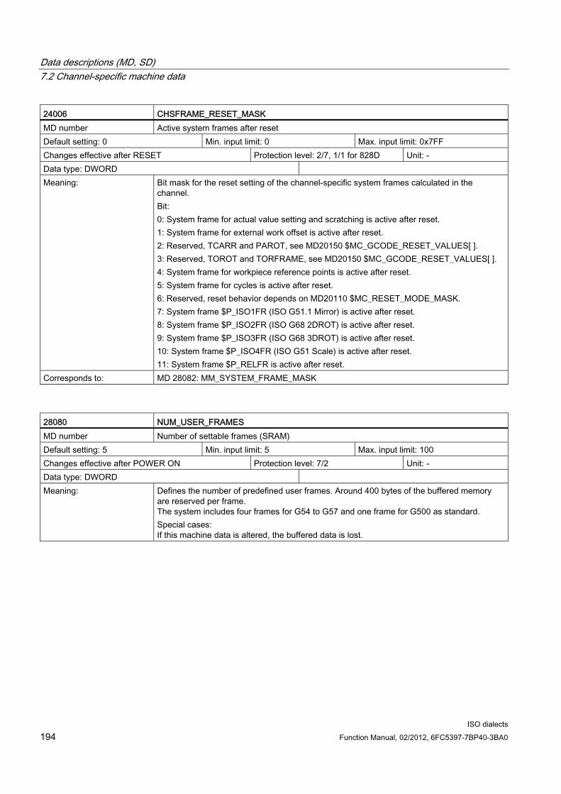
Data descriptions (MD, SD) 7.2 Channel-specific machine data
ISO dialects 194 Function Manual, 02/2012, 6FC5397-7BP40-3BA0
24006 CHSFRAME_RESET_MASK MD number Active system frames after reset Default setting: 0 Min. input limit: 0 Max. input limit: 0x7FF Changes effective after RESET Protection level: 2/7, 1/1 for 828D Unit: - Data type: DWORD Meaning: Bit mask for the reset setting of the channel-specific system frames calculated in the
channel. Bit: 0: System frame for actual value setting and scratching is active after reset. 1: System frame for external work offset is active after reset. 2: Reserved, TCARR and PAROT, see MD20150 $MC_GCODE_RESET_VALUES[ ]. 3: Reserved, TOROT and TORFRAME, see MD20150 $MC_GCODE_RESET_VALUES[ ]. 4: System frame for workpiece reference points is active after reset. 5: System frame for cycles is active after reset. 6: Reserved, reset behavior depends on MD20110 $MC_RESET_MODE_MASK. 7: System frame $P_ISO1FR (ISO G51.1 Mirror) is active after reset. 8: System frame $P_ISO2FR (ISO G68 2DROT) is active after reset. 9: System frame $P_ISO3FR (ISO G68 3DROT) is active after reset. 10: System frame $P_ISO4FR (ISO G51 Scale) is active after reset. 11: System frame $P_RELFR is active after reset.
Corresponds to: MD 28082: MM_SYSTEM_FRAME_MASK
28080 NUM_USER_FRAMES MD number Number of settable frames (SRAM) Default setting: 5 Min. input limit: 5 Max. input limit: 100 Changes effective after POWER ON Protection level: 7/2 Unit: - Data type: DWORD Meaning: Defines the number of predefined user frames. Around 400 bytes of the buffered memory
are reserved per frame. The system includes four frames for G54 to G57 and one frame for G500 as standard. Special cases: If this machine data is altered, the buffered data is lost.

Data descriptions (MD, SD) 7.2 Channel-specific machine data
ISO dialects Function Manual, 02/2012, 6FC5397-7BP40-3BA0 195
28082 MM_SYSTEM_FRAME_MASK MD number System frames (SRAM) Default setting: 0x21, 0x21,... Min. input limit: 0 Max. input limit: 0x0000FF Changes effective after POWER ON Protection level: 7/2 Unit: - Data type: DWORD Meaning: Bit mask for the configuration of the channel-specific system frames calculated in the
channel. Bit: 0: System frame for actual value setting and scratching 1: System frame for external work offset 2: System frame for TCARR and PAROT 3: System frame for TOROT and TORFRAME 4: System frame for workpiece reference points 5: System frame for cycles 6: System frame for transformations 7: System frame for $P_ISO1FR for ISO G51.1 Mirror 8: System frame for $P_ISO2FR for ISO G68 2DROT 9: System frame for $P_ISO3FR for ISO G68 3DROT 10: System frame for $P_ISO4FR for ISO G51 Scale 11: System frame $P_RELFR for relative coordinate systems
28210 MM_NUM_PROTECT_AREA_ACTIVE MD number Number of simultaneously active protection zones in one channel Default setting: 0 Min. input limit: 0 Max. input limit: 10 Changes effective after POWER ON Protection level: 7/2 Unit: - Data type: DWORD Meaning: This machine data states how many protection zones may be activated at the same time for
each channel. A numerical value greater than MD18190 MM_NUM_PROTECT_AREA_NCK + MD28200 MM_NUM_PROTECT_AREA_CHAN is not recommended.
Corresponds to: MD28200 MM_NUM_PROTECT_AREA_CHAN MD18190 MM_NUM_PROTECT_AREA_NCK

Data descriptions (MD, SD) 7.3 Axis-specific machine data
ISO dialects 196 Function Manual, 02/2012, 6FC5397-7BP40-3BA0
7.3 Axis-specific machine data
Table 7- 3
34100 REFP_SET_POS MD number Reference point for distance-coded system Default setting: 0 Min. input limit: -45000000 Max. input limit: +45000000 Changes effective after RESET Protection level: 7/2 Unit: mm, degrees Data type: DOUBLE Meaning: - Incremental encoder with zero mark(s):
The position value which is set as the current axis position after the zero mark has been detected and after traversing distance REFP_MOVE_DIST + REFP_MOVE_DIST_CORR (relative to zero mark). REFP_SET_POS of the reference point number set at the time of the positive edge of the reference cam signal (NC/PLC interface signal (reference point value 1-4)) is set as the axis position. - Distance-coded measuring system: Target position which is approached when MD34330 $MA_REFP_STO_AT_ABS_MARKER is set to 0 (FALSE) and two zero marks have been passed. - Absolute value encoder: MD34100 $MA_REFP_SET_POS corresponds to the current actual value at the adjustment position. The reaction on the machine depends on the status of MD34210 $MA_ENC_REFP_STATE:When ENC_REFP_STATE = 1, the value of REFP_SET_POS is taken as the absolute value. When MD34210 $MA_ENC_REFP_STATE = 2 and MD34330 $MA_REFP_STOP_AT_ABS_MARKER = 0 (FALSE), the axis approaches the target position saved in MD34100 REFP_SET_POS. The value of $MA_REFP_SET_POS which is set using (NC/PLC interface signal (reference point value 1-4)) is used.
Corresponds to: NC/PLC interface signal DB31.DBX2.4-2.7 (reference point value 1-4)
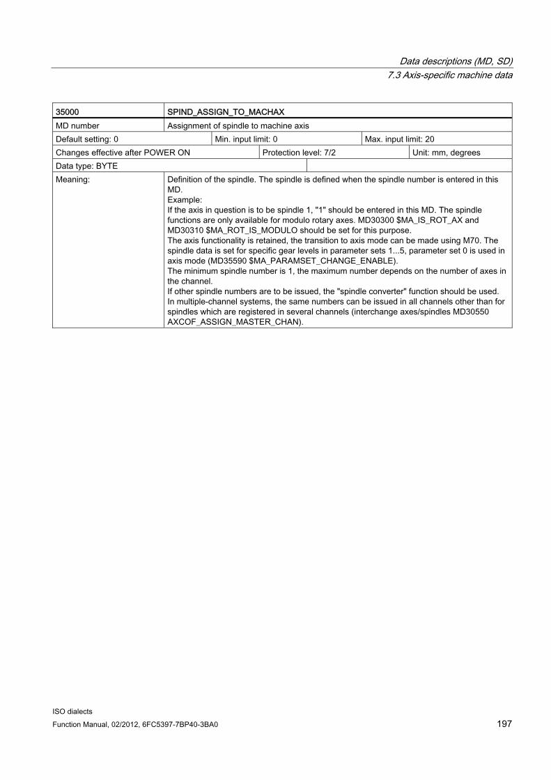
Data descriptions (MD, SD) 7.3 Axis-specific machine data
ISO dialects Function Manual, 02/2012, 6FC5397-7BP40-3BA0 197
35000 SPIND_ASSIGN_TO_MACHAX MD number Assignment of spindle to machine axis Default setting: 0 Min. input limit: 0 Max. input limit: 20 Changes effective after POWER ON Protection level: 7/2 Unit: mm, degrees Data type: BYTE Meaning: Definition of the spindle. The spindle is defined when the spindle number is entered in this
MD. Example: If the axis in question is to be spindle 1, "1" should be entered in this MD. The spindle functions are only available for modulo rotary axes. MD30300 $MA_IS_ROT_AX and MD30310 $MA_ROT_IS_MODULO should be set for this purpose. The axis functionality is retained, the transition to axis mode can be made using M70. The spindle data is set for specific gear levels in parameter sets 1...5, parameter set 0 is used in axis mode (MD35590 $MA_PARAMSET_CHANGE_ENABLE). The minimum spindle number is 1, the maximum number depends on the number of axes in the channel. If other spindle numbers are to be issued, the "spindle converter" function should be used. In multiple-channel systems, the same numbers can be issued in all channels other than for spindles which are registered in several channels (interchange axes/spindles MD30550 AXCOF_ASSIGN_MASTER_CHAN).
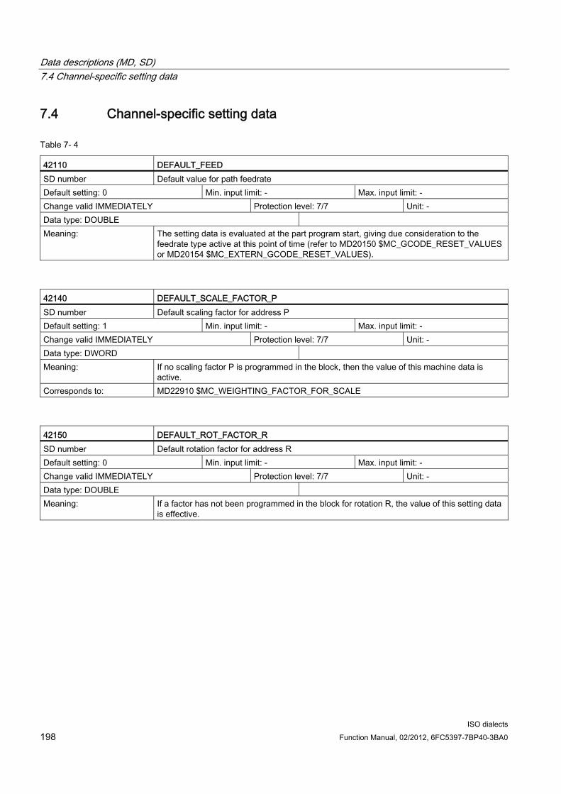
Data descriptions (MD, SD) 7.4 Channel-specific setting data
ISO dialects 198 Function Manual, 02/2012, 6FC5397-7BP40-3BA0
7.4 Channel-specific setting data
Table 7- 4
42110 DEFAULT_FEED SD number Default value for path feedrate Default setting: 0 Min. input limit: - Max. input limit: - Change valid IMMEDIATELY Protection level: 7/7 Unit: - Data type: DOUBLE Meaning: The setting data is evaluated at the part program start, giving due consideration to the
feedrate type active at this point of time (refer to MD20150 $MC_GCODE_RESET_VALUES or MD20154 $MC_EXTERN_GCODE_RESET_VALUES).
42140 DEFAULT_SCALE_FACTOR_P SD number Default scaling factor for address P Default setting: 1 Min. input limit: - Max. input limit: - Change valid IMMEDIATELY Protection level: 7/7 Unit: - Data type: DWORD Meaning: If no scaling factor P is programmed in the block, then the value of this machine data is
active. Corresponds to: MD22910 $MC_WEIGHTING_FACTOR_FOR_SCALE
42150 DEFAULT_ROT_FACTOR_R SD number Default rotation factor for address R Default setting: 0 Min. input limit: - Max. input limit: - Change valid IMMEDIATELY Protection level: 7/7 Unit: - Data type: DOUBLE Meaning: If a factor has not been programmed in the block for rotation R, the value of this setting data
is effective.

Data descriptions (MD, SD) 7.4 Channel-specific setting data
ISO dialects Function Manual, 02/2012, 6FC5397-7BP40-3BA0 199
42160 EXTERN_FIXED_FEEDRATE_F1_F9 SD number Fixed feedrates F1 - F9 Default setting: 0 Min. input limit: - Max. input limit: - Change valid IMMEDIATELY Protection level: 7/7 Unit: - Data type: DOUBLE Meaning: Fixed feedrate values for the programming with F1 -F9. If the machine data
$MC_FEEDRATE_F1_F9 = TRUE is set, the feedrate values from the setting data SD42160 $SC_EXTERN_FIXED_FEEDRATE_F1_F9[0] - $SC_EXTERN_FIXED_FEEDRATE_F1_F9[8] are read and activated as machining feedrate with the programming of F1 to F9. The rapid traverse feedrate must be entered in SD42160 $SC_EXTERN_FIXED_FEEDRATE_F1_F9[0].
42162 EXTERN_DOUBLE_TURRET_DIST SD number Tool distance of double turret head Default setting: 0 Min. input limit: - Max. input limit: Change valid IMMEDIATELY Protection level: 7/7 Unit: - Data type: DOUBLE Meaning: Distance between two tools of one double slide turret head. The distance is activated with
G68 as additive work offset, if MD10812 $MN_EXTERN_DOUBLE_TURRET_ON = TRUE is set.
42520 CORNER_SLOWDOWWN_START SD number Start of feedrate reduction in G62 Default setting: 0 Min. input limit: - Max. input limit: Any Change valid IMMEDIATELY Protection level: 7/7 Unit: mm Data type: DOUBLE Meaning: Path length from which the feedrate is reduced before the corner in G62.
42522 CORNER_SLOWDOWN_END SD number End of feedrate reduction in G62 Default setting: 0 Min. input limit: - Max. input limit: Any Change valid IMMEDIATELY Protection level: 7/7 Unit: mm Data type: DOUBLE Meaning: Path length up to which the feedrate remains reduced after a corner in G62.

Data descriptions (MD, SD) 7.4 Channel-specific setting data
ISO dialects 200 Function Manual, 02/2012, 6FC5397-7BP40-3BA0
42524 CORNER_SLOWDOWN_OVR SD number Override for feedrate reduction in G62 Default setting: 0 Min. input limit: - Max. input limit: - Change valid IMMEDIATELY Protection level: 7/7 Unit: % Data type: DOUBLE Meaning: Override with which the feedrate is multiplied at the corner in G62.
42526 CORNER_SLOWDOWN_CRIT SD number Corner detection for G62 Default setting: 0 Min. input limit: - Max. input limit: - Change valid IMMEDIATELY Protection level: 7/7 Unit: Degrees Data type: DOUBLE Meaning: Angle from which a corner is considered for the feedrate reduction with G62, e.g. SD42526
CORNER_SLOWDOWN_CRIT=90: All corners of 90 degrees or less are traversed slower with G62.

Data descriptions (MD, SD) 7.4 Channel-specific setting data
ISO dialects Function Manual, 02/2012, 6FC5397-7BP40-3BA0 201
42940 TOOL_LENGTH_CONST SD number Change of tool length components for change of plane Default setting: 0 Min. input limit: - Max. input limit: - Change valid IMMEDIATELY Protection level: 7/7 Unit: Data type: DWORD Meaning: If this setting data is not zero, the assignment of tool lengths 1 to 3 (length, wear, tool base
dimension) to the geometry axes when changing machining plane (G17 to G19) is not changed. The assignment of tool length components to geometry axes results from the setting data value according to the table below. During assignment, a distinction is made between turning and grinding tools (tool types 400 to 599) and other tools (typically milling tools). The representation in the tables assumes that geometry axes 1 to 3 are identified as X, Y and Z. The axis order and not the axis identifier determines the assignment between a compensation and an axis. Assignment for turning and grinding tools (tool type 400 to 599): Content - Length 1 - Length 2 - Length 3 17 Y X Z 18*) X Z Y 19 Z Y X -17 X Y Z -18 Z X Y -19 Y Z X * Each value not equal to 0, which is not equal to one of the six listed values, is evaluated as value 18. If values are of the same amount but have different signs, the assignment of length 3 is the same and lengths 1 and 2 are swapped. Assignment for all tools which are not turning or grinding tools (tool types < 400 or > 599): Content - Length 1 - Length 2 - Length 3 17*) Z Y X 18 Y X Z 19 X Z Y -17 Z X Y -18 Y Z X -19 X Y Z * Each value not equal to 0, which is not equal to one of the six listed values, is evaluated as value 17. If values are of the same amount but have different signs, the assignment of length 1 is the same and lengths 2 and 3 are swapped.

Data descriptions (MD, SD) 7.4 Channel-specific setting data
ISO dialects 202 Function Manual, 02/2012, 6FC5397-7BP40-3BA0
42950 TOOL_LENGTH_TYPE SD number Assignment of the tool length compensation independent of tool type Default setting: 0 Min. input limit: 0 Max. input limit: 2 Change valid IMMEDIATELY Protection level: 7/7 Unit: Data type: DWORD Meaning: This setting data defines the assignment of tool length components to geometry axes
regardless of tool type. Values between 0 and 2 can be accepted. Any other value is interpreted as 0. 0: The assignment is performed by default. A distinction is made between turning tools (tool types 400 to 599) and other tools (milling tools). 1: The assignment of the tool length components is, independent of the actual tool type, always the same as for milling tools. 2: The assignment of the tool length components is, independent of the actual tool type, always the same as for turning tools. The setting data also affects the wear values assigned to length components. If SD42940 $SC_TOOL_LENGTH_CONST is set, the table for milling and/or turning tools defined by SD42950 $SC_TOOL_LENGTH_TYPE is accessed in the tables defined there regardless of the actual tool type if the value of the turning tools is not 0.
42990 MAX_BLOCKS_IN_IPOBUFFER SD number Max. number of blocks in the IPO buffer Default setting: -1 Min. input limit: - Max. input limit: - Change valid IMMEDIATELY Protection level: 7/7 Unit: Data type: DWORD Meaning: This setting data can be used to limit the maximum number of blocks in the interpolation
buffer. The maximum number is defined by MD28060 MM_IPO_BUFFER_SIZE. A negative value means that the number of blocks in the IPO buffer is not limited and the number of blocks is determined by MD MM_IPO_BUFFER_SIZE alone (standard setting).
42995 CONE_ANGEL SD number Taper angle Default setting: 0 Min. input limit: -90 Max. input limit: +90 Change valid IMMEDIATELY Protection level: 7/7 Unit: Degrees Data type: DOUBLE Meaning: This setting data describes the taper angle for taper turning. This setting data is written
using the user interface.

Data descriptions (MD, SD) 7.5 Axis-specific setting data
ISO dialects Function Manual, 02/2012, 6FC5397-7BP40-3BA0 203
7.5 Axis-specific setting data
Table 7- 5
43120 DEFAULT_SCALE_FACTOR_AXIS SD number Default axial scaling factor with active G51 Default setting: 1 Min. input limit: - Max. input limit: - Change valid IMMEDIATELY Protection level: 7/7 Unit: - Data type: DWORD Meaning: If no axial scaling factor I, J or K is programmed in the G51 block, then the SD43120
DEFAULT_SCALEFACTOR_AXIS is active. For the scaling factor to be effective, the MD22914 AXES_SCALE_ENABLE must be set.
Corresponds to: MD22914 $MC_AXES_SCALE_ENABLE MD22910 $MC_WEIGTING_FACTOR_FOR_SCALE
43240 M19_SPOS SD number Spindle position for spindle positioning with M19 Default setting: 0 Min. input limit: -10000000.0 Max. input limit: +10000000.0 Change valid IMMEDIATELY Protection level: 7/7 Unit: Degrees Data type: DOUBLE Meaning: Spindle position in [degrees] for spindle positioning with M19. The position approach mode
is defined in $A_M19_SPOSMODE. Position specifications must be in the range 0<pos<$MA_MODULO_RANGE. Path specifications ($SA_M19_SPOSMODE = 2) may be positive or negative and are restricted by input format alone
43340 EXTERN_REF_POSITION_G30_1 SD number Reference point position for G30.1 Default setting: 0.0 Min. input limit: Max. input limit: Change valid IMMEDIATELY Protection level: 7/7 Unit: Data type: DOUBLE Meaning: Reference point position for G30.1.
This setting data is evaluated in CYCLE328.

Data descriptions (MD, SD) 7.6 Channel-specific cycle machine data
ISO dialects 204 Function Manual, 02/2012, 6FC5397-7BP40-3BA0
7.6 Channel-specific cycle machine data
Table 7- 6
52800 ISO_M_ENABLE_POLAR_COORD MD number Polar coordinates Default setting: 0 Min. input limit: 0 Max. input limit: 1 Change valid IMMEDIATELY Protection level: 7/3 Unit: - Data type: BYTE Meaning: Polar coordinates
0: OFF 1: ON
52802 ISO_ENABLE_INTERRUPTS MD number Interrupt processing Default setting: 0 Min. input limit: 0 Max. input limit: 1 Change valid IMMEDIATELY Protection level: 7/3 Unit: - Data type: BYTE Meaning: Interrupt processing
0: OFF 1: ON
52804 ISO_ENABLE_DRYRUN MD number Processing skip during DRYRUN Default setting: 0 Min. input limit: 0 Max. input limit: 1 Change valid IMMEDIATELY Protection level: 7/3 Unit: - Data type: BYTE Meaning: Processing skip when tapping G74/G84 during DRYRUN
0: OFF 1: ON
52806 ISO_SCALING_SYSTEM MD number Basic system Default setting: 0 Min. input limit: 0 Max. input limit: 2 Change valid IMMEDIATELY Protection level: 7/3 Unit: - Data type: BYTE Meaning: Basic system
0: Not defined 1: METRIC 2: INCH

Data descriptions (MD, SD) 7.6 Channel-specific cycle machine data
ISO dialects Function Manual, 02/2012, 6FC5397-7BP40-3BA0 205
52808 ISO_SIMULTAN_AXES_START MD number Simultaneous drill position approach for all programmed axes Default setting: 0 Min. input limit: 0 Max. input limit: 1 Change valid IMMEDIATELY Protection level: 7/3 Unit: - Data type: BYTE Meaning: Simultaneous drill position approach for all programmed axes
0: OFF 1: ON
52810 ISO_T_DEEPHOLE_DRILL_MODE MD number Deep-hole drilling with chip breaking / removal of chips Default setting: 0 Min. input limit: 0 Max. input limit: 1 Change valid IMMEDIATELY Protection level: 7/3 Unit: - Data type: BYTE Meaning: Selection of deep-hole drilling type
Deep-hole drilling with chip breaking Deep-hole drilling with removal of chips

Data descriptions (MD, SD) 7.7 Channel-specific cycle setting data
ISO dialects 206 Function Manual, 02/2012, 6FC5397-7BP40-3BA0
7.7 Channel-specific cycle setting data 55800 $SCS_ISO_M_DRILLING_AXIS_IS_Z SD number Drilling axis depends on plane / always Z Default setting: 0 Min. input limit: 0 Max. input limit: 1 Change valid IMMEDIATELY Protection level: 7/6 Unit: - Data type: BYTE Meaning: Selection of drilling axis
0: Drilling axis is vertical to active plane 1: Drilling axis is always "Z" regardless of the active plane
55802 $SCS_ISO_M_DRILLING_TYPE SD number Tapping type Default setting: 0 Min. input limit: 0 Max. input limit: 3 Change valid IMMEDIATELY Protection level: 7/6 Unit: - Data type: BYTE Meaning: Selection of drilling axis
0: Tapping without compensating chuck 1: Tapping with compensating chuck 2: Deep-hole tapping with chip breakage 3: Deep-hole tapping with chip removal
55804 $SCS_ISO_M_RETRACTION_FACTOR SD number Factor for retraction speed (0...200%) Default setting: 100 Min. input limit: 0 Max. input limit: 200 Change valid IMMEDIATELY Protection level: 7/6 Unit: - Data type: DWORD Meaning: Factor for retraction speed (0...200%)
55806 $SCS_ISO_M_RETRACTION_DIR SD number Retraction direction for G76/G87 Default setting: 0 Min. input limit: 0 Max. input limit: 4 Change valid IMMEDIATELY Protection level: 7/6 Unit: - Data type: DWORD Meaning: Retraction direction for precision drilling and reverse countersinking G76/G87
0: G17(-X) G18(-Z) G19(-Y) 1: G17(+X) G18(+Z) G19(+Y) 2: G17(-X) G18(-Z) G19(-Y) 3: G17(+Y) G18(+X) G19(+Z) 4: G17(-Y) G18(-X) G19(-Z)
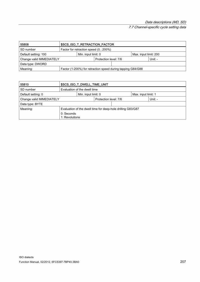
Data descriptions (MD, SD) 7.7 Channel-specific cycle setting data
ISO dialects Function Manual, 02/2012, 6FC5397-7BP40-3BA0 207
55808 $SCS_ISO_T_RETRACTION_FACTOR SD number Factor for retraction speed (0...200%) Default setting: 100 Min. input limit: 0 Max. input limit: 200 Change valid IMMEDIATELY Protection level: 7/6 Unit: - Data type: DWORD Meaning: Factor (1-200%) for retraction speed during tapping G84/G88
55810 $SCS_ISO_T_DWELL_TIME_UNIT SD number Evaluation of the dwell time Default setting: 0 Min. input limit: 0 Max. input limit: 1 Change valid IMMEDIATELY Protection level: 7/6 Unit: - Data type: BYTE Meaning: Evaluation of the dwell time for deep-hole drilling G83/G87
0: Seconds 1: Revolutions

Data descriptions (MD, SD) 7.7 Channel-specific cycle setting data
ISO dialects 208 Function Manual, 02/2012, 6FC5397-7BP40-3BA0

ISO dialects Function Manual, 02/2012, 6FC5397-7BP40-3BA0 209
Data fields, lists 88.1 Machine data
Table 8- 1
Number Identifier Name General ($MN_ ... ) 10604 WALIM_GEOAX_CHANGE_MODE Working area limitation during switchover of geometry axes 10615 NCFRAME_POWERON_MASK Reset global basic frames after power on 10652 CONTOUR_DEF_ANGLE_NAME Name of angle for contour definitions 10654 RADIUS_NAME Name of radius for contour definitions 10656 CHAMFER_NAME Name of chamfer for contour definitions 10704 DRYRUN_MASK Activation of dry run feedrate 10706 SLASH_MASK Activation of block skip function 10715 M_NO_FCT_CYCLE[n]: 0, ..., 0 M function to be replaced by subroutine 10716 M_NO_FCT_CYCLE_NAME[ ] Subprograms for M function replacement 10717 T_NO_FCT_CYCLE_NAME Name of tool-changing cycle for T function 10718 M_NO_FCT_CYCLE_PAR M function replacement with parameters 10719 T_NO_FCT_CYCLE_MODE Parameter assignment for T function replacement 10760 G53_TOOLCORR Mode of operation G53, G153 and SUPA 10800 EXTERN_CHAN_SYNC_M_NO_MIN 1st M function for channel synchronization 10802 EXTERN_CHAN_SYNC_M_NO_MAX Last M function for channel synchronization 10804 EXTERN_M_NO_SET_INT M function for ASUB activation 10806 EXTERN_M_NO_DISABLE_INT M function for ASUB deactivation 10808 EXTERN_INTERRUPT_BITS_M96 Activate interrupt program (ASUB) 10810 EXTERN_MEAS_G31_P_SIGNAL Assignment of measuring inputs for G31 P.. 10812 EXTERN_DOUBLE_TURRET_ON Double turret head with G68 10814 EXTERN_M_NO_MAC_CYCLE Subprogram name for macro call via M function 10815 EXTERN_M_NO_MAC_CYCLE_NAME Subprogram name for M function macro call 10816 EXTERN_G_NO_MAC_CYCLE Macro call for macro call via G functions 10817 EXTERN_G_NO_MAC_CYCLE_NAME Subprogram name for G function macro call 10818 EXTERN_INTERRUPT_NUM_ASUP Interrupt number for ASUB start (M96) 10820 EXTERN_INTERRUPT_NUM_RETRAC Interrupt number for rapid retraction (G10.6) 10880 EXTERN_CNC_SYSTEM Definition of the control system to be adapted 10881 EXTERN_GCODE_SYSTEM ISO mode T: G code system 10882 NC_USER_EXTERN_GCODES_TAB[n]: 0-59 List of user-specific G commands of an external NC
language 10884 EXTERN_FLOATINGPOINT_PROG Evaluation of programmed values without decimal point 10886 EXTERN_INCREMENT_SYSTEM Increment system in the external language mode 10888 EXTERN_DIGITS_TOOL_NO Number of digits for T number in ISO mode

Data fields, lists 8.1 Machine data
ISO dialects 210 Function Manual, 02/2012, 6FC5397-7BP40-3BA0
Number Identifier Name 10889 EXTERN_DIGITS_OFFSET_NO Number of digits for compensation numbers in ISO mode 10890 EXTERN_TOOLPROG_MODE Tool change program of external language 18800 MM_EXTERN_LANGUAGE Activation of external NC languages Channel-specific ($MC_ ... ) 20050 AXCONF_GEOAX_ASSIGN_TAB[ ] Assignment of geometry axis to channel axis 20060 AXCONF_GEOAX_NAME_TAB[ ] Geometry axis number in the channel 20070 AXCONF_MACHAX_USED[ ] Machine axis number valid in the channel 20080 AXCONF_CHANAX_NAME_TAB[ ] Name of channel axis in the channel 20094 SPIND_RIGID_TAPPING_M_NR M function for switching over to controlled axis mode 20095 EXTERN_RIGID_TAPPING_M_NR M function for changing over to the controlled axis mode
(external language mode) 20100 DIAMETER_AX_DEF Geometry axis with transverse axis function 20150 GCODE_RESET_VALUES[n]: 0 to max.
number of G codes Initial setting of the G groups
20152 GCODE_RESET_MODE Reset behavior of G group 20154 EXTERN_GCODE_RESET_VALUES[n]: 0-30 Reset G groups in ISO mode 20156 EXTERN_GCODE_RESET_MODE Reset behavior of the external G groups 20380 TOOL_CORR_MODE_G43G44 Handling the tool length compensation for G43/G44 20382 TOOL_CORR_MOVE_MODE Retract the tool length compensation 20732 EXTERN_G0_LINEAR_MODE Interpolation behavior with G00 20734 EXTERN_FUNCTION_MASK Function mask for external language 22420 FGROUP_DEFAULT_AXES[ ] Default value for FGROUP command 22512 EXTERN_GCODE_GROUPS_TO_PLC[n]: 0-7 Transmit G command of an external NC language to PLC 22515 GCODE_GROUPS_TO_PLC_MODE Response of the G group transfer to PLC 22900 STROKE_CHECK_INSIDE Direction (inside/outside) in which protection zone 3 is
effective 22910 WEIGHTING_FACTOR_FOR_SCALE Input resolution for scaling factor 22914 AXES_SCALE_ENABLE Activation for axial scaling factor (G51) 22920 EXTERN_FEEDRATE_F1_F9_ACTIV Activation of fixed feedrates with F1-F9 22930 EXTERN_PARALLEL_GEOAX Assignment of a parallel channel axis to the geometry axis 24004 CHBFRAME_POWERON_MASK Reset channel-specific basic frame after Power On 24006 CHSFRAME_RESET_MASK Active system frames after reset 28080 NUM_USER_FRAMES Number of settable frames (SRAM) 28082 MM_SYSTEM_FRAME_MASK System frames (SRAM) 28210 NUM_PROTECT_AREA_ACTIVE Number of simultaneously active protection zones in one
channel Axis-specific ($MA_ ... 34100 REFP_SET_POS[0] Reference points for distance-coded system 35000 SPIND_ASSIGN_TO_MACHAX Assignment of spindle to machine axis

Data fields, lists 8.1 Machine data
ISO dialects Function Manual, 02/2012, 6FC5397-7BP40-3BA0 211
Channel-specific cycle machine data
Number Identifier Name 52800 ISO_M_ENABLE_POLAR_COORD Polar coordinates 52802 ISO_ENABLE_INTERRUPTS Interrupt processing 52804 ISO_ENABLE_DRYRUN Processing skip during DRYRUN 52806 ISO_SCALING_SYSTEM Basic system 52808 ISO_SIMULTAN_AXES_START Simultaneous drill position approach for all programmed
axes 52810 ISO_T_DEEPHOLE_DRILL_MODE Deep-hole drilling with chip breaking / removal of chips

Data fields, lists 8.2 Setting data
ISO dialects 212 Function Manual, 02/2012, 6FC5397-7BP40-3BA0
8.2 Setting data
Table 8- 2
Number Identifier Name Channel-specific 42110 DEFAULT_FEED Default value for path feedrate 42140 DEFAULT_SCALE_FACTOR_P Default scaling factor for address P 42150 DEFAULT_ROT_FACTOR_R Default rotation factor for address R 42160 EXTERN_FIXED_FEEDRATE_F1_F9 Fixed feedrates with F1-F9 42162 EXTERN_DOUBLE_TURRET_DIST Tool distance of double turret head 42520 CORNER_SLOWDOWN_START Start of feedrate reduction in G62 42522 CORNER_SLOWDOWN_END End of feedrate reduction in G62 42524 CORNER_SLOWDOWN_OVR Override for feedrate reduction in G62 42526 CORNER_SLOWDOWN_CRIT Corner detection for G62 42940 TOOL_LENGTH_CONST Change of tool length components for change of plane 42950 TOOL_LENGTH_TYPE Assignment of the tool length compensation independent of
tool type 42990 MAX_BLOCKS_IN_IPOBUFFER Maximum number of blocks in the IPO buffer 42995 CONE_ANGLE Taper angle Axis-specific 43120 DEFAULT_SCALE_FACTOR_AXIS Default axial scaling factor with active G51 43240 M19_SPOS Spindle position for spindle positioning with M19 43340 EXTERN_REF_POSITION_G30_1 Reference point position for G30.1
Channel-specific cycle setting data
Number Identifier Name 55800 ISO_M_DRILLING_AXIS_IS_Z Drilling axis depends on plane / always Z 55802 ISO_M_DRILLING_TYPE Tapping type 55804 ISO_M_RETRACTION_FACTOR Factor for retraction speed (0...200%) 55806 ISO_M_RETRACTION_DIR Retraction direction for G76/G87 55808 ISO_T_RETRACTION_FACTOR Factor for retraction speed (0...200%) 42520 ISO_T_DWWELL_TIME_UNIT Evaluation of the dwell time

ISO dialects Function Manual, 02/2012, 6FC5397-7BP40-3BA0 213
Alarms 9
If error conditions are detected in cycles, an alarm is generated and the execution of the cycle is aborted.
The cycles continue to output messages in the dialog line of the control. These message will not interrupt the program execution.
Alarms with numbers between 61000 and 62999 are generated in the cycles (see /DA/, Diagnostics Manual and /PGZ/, Cycles, Programming Manual). This range of numbers, in turn, is divided again with regard to alarm responses and cancel criteria.
The table below also contains error messages for the cycles described in the chapter "Cycles and contour definition".
Table 9- 1 Alarm no. and alarm description
Alarm no. Short description Source Explanation/remedy Alarms - in general 61001 Thread lead incorrectly defined CYCLE376T Thread lead incorrectly defined 61003 No feedrate programmed in cycle CYCLE371T, CYCLE374T,
CYCLE383T, CYCLE384T, CYCLE385T, CYCLE381M, CYCLE383M, CYCLE384M, CYCLE387M
No "F" feedrate was programmed in the call block or before the cycle call, refer to Siemens standard cycles
61004 Configuration of geometry axis is not correct
CYCLE328 The sequence of the geometry axes is incorrect, refer to Siemens standard cycles
61101 Reference plane incorrectly defined
CYCLE375T, CYCLE81, CYCLE83, CYCLE84, CYCLE87
Refer to Siemens standard cycles
61102 No spindle direction programmed CYCLE371T, CYCLE374T, CYCLE383T, CYCLE384T, CYCLE385T, CYCLE381M, CYCLE383M, CYCLE384M, CYCLE387M
Spindle direction M03 or M04 is missing, refer to Siemens standard cycles
61107 First drilling depth incorrectly defined
First drilling depth contradicts total drilling depth
61603 Groove shape incorrectly defined CYCLE374T Groove depth is 0 61607 Start time incorrectly defined CYCLE376T The start point reached before the
cycle call is not outside the range to be processed
61610 No infeed depth programmed CYCLE374T Infeed depth is 0.

Alarms
ISO dialects 214 Function Manual, 02/2012, 6FC5397-7BP40-3BA0
Alarm no. Short description Source Explanation/remedy ISO alarms 61800 External CNC system is missing CYCLE300, CYCLE328,
CYCLE330, CYCLE371T, CYCLE374T, CYCLE376T, CYCLE383T, CYCLE384T, CYCLE385T, CYCLE381M, CYCLE383M, CYCLE384M, CYCLE387M
Machine datum for external language MD18800: $MN_MM_EXTERN_LANGUAGE and/or option bit 19800 $ON_EXTERN_LANGUAGE is not set
61801 Wrong G code selected CYCLE300, CYCLE371T, CYCLE374T, CYCLE376T, CYCLE383T, CYCLE384T, CYCLE385T
An impermissible numerical value has been programmed in the CYCLE300<value> cycle call, for the CNC system entered, or an incorrect value has been stated for the G code system in the cycle setting datum.
61802 Wrong axis type CYCLE328, CYCLE330 The programmed axis is assigned to a spindle
61803 Programmed axis does not exist CYCLE328, CYCLE330 The programmed axis does not exist in the system. Check MD20050-20080
61804 Programmed position exceeds home position
CYCLE328, CYCLE330 The programmed intermediate position or the current position is after the home position.
61805 Value programmed as absolute and incremental
CYCLE328, CYCLE330, CYCLE371T, CYCLE374T, CYCLE376T, CYCLE383T, CYCLE384T, CYCLE385T
The programmed intermediate position is programmed as absolute as well as incremental.
61806 Wrong axis assignment CYCLE328 The sequence of the axis assignment is wrong
61807 Incorrect spindle direction programmed (active)
CYCLE384M The programmed spindle direction contradicts the spindle direction provided for the cycle
61808 Final drilling depth or single drilling depth is missing
CYCLE383T, CYCLE384T, CYCLE385T, CYCLE381M, CYCLE383M, CYCLE384M, CYCLE387M
Total depth "Z" or single drilling depth "Q" is missing in the G8x block (first call of cycle)
61809 Drilling position not permissible CYCLE383T, CYCLE384T, CYCLE385T
61810 ISO G code not possible CYCLE383T, CYCLE384T, CYCLE385T
61811 ISO axis name not permissible CYCLE328, CYCLE330. CYCLE371T, CYCLE374T, CYCLE376T, CLE383T, CYCLE384T, CYCLE385T
An impermissible ISO axis name has been programmed in the call block
61812 Value(s) in the external cycle call is incorrectly defined
CYCLE371T, CYCLE376T, An impermissible numerical value has been programmed in the call block

Alarms
ISO dialects Function Manual, 02/2012, 6FC5397-7BP40-3BA0 215
Alarm no. Short description Source Explanation/remedy 61813 GUD value incorrectly defined CYCLE376T An impermissible numerical value
was entered in the cycle setting data
61814 Polar coordinates not possible CYCLE381M, CYCLE383M, CYCLE384M, CYCLE387M
61815 G40 not active CYCLE374T, CYCLE376T G40 was not active before the cycle call
61816 Axes not at home position 61817 Axis coordinates within protection
zone
61818 Axis limit values are the same

Alarms
ISO dialects 216 Function Manual, 02/2012, 6FC5397-7BP40-3BA0

ISO dialects Function Manual, 02/2012, 6FC5397-7BP40-3BA0 217
Index
$ $P_STACK, 82 $TC_DPH, 91
2 2D/3D rotation G68/69
ISO-M, 37
A Activating ISO dialect mode, 137 Alarms, 213 Approach 1st reference point G28, 141 Approach 2nd/3rd/4th reference point
G30, 142 Approaching 1st home position, 54 Axis interpolation, 137
B B, 53 B function, 53 Backlash compensation, 36 Block number, 69 Block skip plane, 52
C Chamfers, 148 Comments, 52 Commissioning
Active G command for PLC, 143 Machine data, 137 Standard machine data assignment, 152 Tool change, 143
Compressor, 55 Compressor function, 55 Contour definitions ISO-T)
Programming, 122 Contour preparation, 68 Contour repetition
G72.1/G72.2, 131
CONTPRON, 68 Corner override, 56 Cycle parameters, 97 CYCLE383T, 116 CYCLE383T shell cycle, 116 CYCLE384T, 117 CYCLE384T shell cycle, 117 CYCLE385T, 118 CYCLE385T shell cycle, 118 Cycles
CYCLE381M shell cycle, 103 CYCLE383M shell cycle, 103 CYCLE384M shell cycle, 105 CYCLE387M shell cycle, 105 Drilling cycles, 100 General, 95 Modally effective, 96 Sequence, 95
Cylindrical interpolation, 46
D D, 53
ISO-M, 85 D function, 53 D numbers, 87 Decimal point, 27 Decimal point programming, 138 Deep-hole drilling, 103 Display of non-modal G codes, 19 Double turret processing, 39 Drilling cycles
G80-G89, 114 DryRun mode, 80 Dwell time, 32
E End point programming with angles, 123 Error messages, 213 Exact stop, 144
F F value, 157 Fast lifting, 30 Feedrates, 146

Index
ISO dialects 218 Function Manual, 02/2012, 6FC5397-7BP40-3BA0
Floating reference position G30.1, 143
G G commands, 13
modally effective, 16 G00, 13 G00, 13 G01, 13 G02, 13 G02.2
ISO-M, 13 G02/G03, 157 G03, 13 G03.2
ISO-M, 13 G04, 15, 32, 157 G05, 15 G05 P.., 79 G05.1, 15 G07.1, 15, 46 G08
ISO-M, 15 G08 P.., 54 G09
ISO-M, 15 G10, 15, 26 G10.6, 15, 30 G11
ISO-M, 15 G12.1, 44
ISO-M, 16 ISO-T, 16
G13.1, 44 ISO-M, 16 ISO-T, 16
G15 ISO-M, 15, 43
G16, 157 ISO-M, 15
G17, 148 ISO-M, 13 ISO-T, 15
G18, 148 ISO-M, 13 ISO-T, 15
G19, 148 ISO-M, 13 ISO-T, 15
G20, 14 G20/G21, 157 G21, 14
G22, 141, 157 ISO-M, 13, 14
G23, 141 ISO-M, 13 ISO-T, 14
G27, 15 G28, 16, 54, 141 G290, 16 G290/291, 11 G291, 16 G30, 16, 142 G30.1, 16, 143 G31, 16, 140 G33, 13, 31 G34, 32
ISO-T, 13 G35, 13 G36, 13 G40, 14, 158 G41, 14 G41/G42, 158 G42, 14 G43
ISO-M, 14 G44
ISO-M, 14 G49
ISO-M, 14 G50
ISO-M, 14 G50.1
ISO-M, 16 G50.2
ISO-T, 16 G51
ISO-M, 14, 33 G51.1
ISO-M, 16, 33, 34 G51.2, 130
ISO-T, 16 G52, 16 G53, 16, 139, 158 G54, 15 G54 P{1...48}, 15 G54 P0, 15 G54.1, 15, 25 G55, 15 G56, 15 G57, 15 G58, 15 G59, 15 G60, 16

Index
ISO dialects Function Manual, 02/2012, 6FC5397-7BP40-3BA0 219
G61 ISO-M, 15
G62, 56 ISO-M, 15
G63, 158 ISO-M, 15
G64 ISO-M, 15
G65, 16, 71 G65, 16, 71 G65/66, 11 G66, 15, 74 G66, 15, 74 G67, 15, 71 G68
ISO-M, 15, 37 ISO-T, 13
G68/G69, 39 G69
ISO-M, 15, 37 ISO-T, 13
G70 ISO-T, 16
G71 ISO-T, 16
G72 ISO-T, 16
G72.1 ISO-M, 16
G72.1/G72.2, 131 G72.2
ISO-M, 16 G73
ISO-M, 14 ISO-T, 16
G73), 104 G74
ISO-M, 14 ISO-T, 16
G75 ISO-T, 16
G76 ISO-M, 14 ISO-T, 16
G77 ISO-T, 13
G78 ISO-T, 13
G79 ISO-T, 13
G80 ISO-M, 14 ISO-T, 14
G81 ISO-M, 14
G82 ISO-M, 14
G83, 103 ISO-M, 14 ISO-T, 14
G84 ISO-M, 14 ISO-T, 14
G85 ISO-M, 14 ISO-T, 14
G86 ISO-M, 14 ISO-T, 14
G87 ISO-M, 14 ISO-T, 14
G89 ISO-M, 14 ISO-T, 14
G90, 13 G91, 13 G92, 16, 139 G92.1, 16, 140 G93
ISO-M, 13 G94, 13 G94/G95, 158 G95, 13 G96, 15
ISO-T, 13 G97
ISO-M, 15 ISO-T, 13
G98 ISO-M, 14 ISO-T, 14
G99 ISO-M, 14 ISO-T, 14
Global user data, 98 GUD, 98
H H, 53 H function, 53 H numbers, 86 High-speed cycle cutting, 79

Index
ISO dialects 220 Function Manual, 02/2012, 6FC5397-7BP40-3BA0
I Inch/metric changeover, 146 Inserting chamfers and radii, 148 Interrupt program with M96/M97, 49 ISO dialect M axis names, 137 ISO dialect M or T
Selection, 137 ISO dialect T axis names, 137
L Level stack, 82
M M
ISO-M, 85 M06, 158 M29, 53 M96, 49 M97, 49 M98, 64 Machine data, 161
Axis-specific, 196, 203 Channel-specific, 178 General, 161 ISO cycles, 204 List, 209
Macro call modal, 73
Macro call via G function, 76 Macro calls
Mode changeover, 74 Macro commands, 71
ISO dialect, 71 Siemens, 71
Mirroring, 33 Multi-edge turning
G51.2, 130
N Non-modal G codes, 19 Number of program runs, 64
O Overview of G commands, 13
P Parallel axes, 148 Polar coordinates, 43 Polar coordinates interpolation, 44 Program coordination, 151 Programmed angle, 43
R Radii, 148 RET, 65 Rotary axis function, 149
S Scaling, 33, 139 Setting data
Channel-specific, 198 List, 212
Shell cycle, 95 Siemens language commands in ISO dialect mode, 67 Skip level, 80 Spindle axis switchover, 53 Spindle revolution, 32 Start label), 69 Straight line with angle
Programming, 124 Subprogram technique, 64 Supplementary conditions
Implied mode change, 156 Mode switchover, 156 Power on, reset, block search, 160 Program commands, 157 Tool management, 159
Switching feedforward control on/off, 54 System variables, 119
T T, 53
ISO-M, 85 ISO-T, 89
T function, 53 Thread
Convex, 136 Multiple, 31 Variable lead, 32
Tool change cycle, 93 Tool length offset, 88 Tool management, 85
Index
ISO dialects Function Manual, 02/2012, 6FC5397-7BP40-3BA0 221
Tool offset T (ISO dialect T), 89
Tool offsets, 85 TRANSMIT, 44 Turning cycles, 106
G77-G79, 111

Index
ISO dialects 222 Function Manual, 02/2012, 6FC5397-7BP40-3BA0