Embed Size (px)
Citation preview
s
SIPROM GA V1.10.5 The Gas Analysis Operation- and Service Tool
Manual A5E01155782-01
Edition 11/2008
SIPROM GA – Software application Manual – A5E01155782-01 i
The reproduction, transmission or use of this document or its contents is not permitted without express written authority. Offenders will be liable for damages. All rights created by the granting of patents or registration of a design are reserved. Technical data subject to change without notice.
ULTRAMAT, OXYMAT, CALOMAT, FIDAMAT are SIEMENS registered trademarks. All other product or system names are (registered) trademarks of their respective owners and must be treated accordingly. According to the German law on units in measuring technology, data in inches only apply to devices for export.
Weitergabe sowie Vervielfältigung dieser Unterlage, Verwertung und Mitteilung ihres Inhaltes nicht gestattet, soweit nicht ausdrücklich zugestanden. Zuwiderhandlungen verpflichten zu Schadenersatz. Alle Rechte vorbehalten, insbesondere für den Fall der Patenterteilung oder GM-Eintragung. Technische Änderungen vorbehalten.
ULTRAMAT, OXYMAT, CALOMAT, FIDAMAT sind Marken der SIEMENS AG. Die übrigen Bezeichnungen in diesem Handbuch können Marken sein, deren Benutzung durch Dritte für deren Zwecke die Rechte der Inhaber verletzen können. Die Angaben in Zoll (inch) gelten gemäß dem Gesetz über Einheiten im Meßwesen" nur für den Export.
Toute communication ou reproduction de ce document, toute exploitation ou communication de son contenu sont interdites, sauf autorisation expresse. Tout manquement à cette règle est illicite et expose son auteur au versement de dommages et intérêts. Tours nos droits sont réservés pour le cas de la délivrance d'un brevet ou celui de l'enregistrement d'un modèle d'utilité. Modifications techniques sont réservées.
ULTRAMAT, OXYMAT, CALOMAT, FIDAMAT sont des marques déposées de SIEMENS AG. D'autres dénominations utilisées dans ce document peuvent également être des marques déposées dont l'utilisation par des tiers à leurs propres fins peut enfreindre les droits des propriétaires desdites marques.
La divulgación y reproducción de este documento asi como el aprovechamiento de su contenido, no están autorizados, a no ser que se obtenga el consentimiento expreso, para ello. Los infractores quedan obligados a la indemnización por daños y perjucios. Se reservan todos los derechos, en particular para el caso de concesion de Patente o de Modelo de Utilidad. Salvo modificaciones ténicas.
ULTRAMAT, OXYMAT, CALOMAT, FIDAMAT son marcas registradas de SIEMENS AG. Las otras designaciones que figuran en este documento puenden ser marcas cuya utilización por terceros para sus propios fines puede violar los derechos de los proprietarios de dichas marcas. Conforma a la "Ley sobre las unidades de medida", las dimensiones en pulgadas sólo son válidas para la exportación.
La trasmissione a terzi e la riproduzione di questa documentazione, cosiccome lo sfruttamento del suo contenuto non è permesso, se non autorizzato per iscritto. Le infrazioni comporteranno una richiesta di danni. Tutti i diritti sono riservati, in particolare nel caso di brevetti. Modifiche tecniche possibili.
ULTRAMAT, OXYMAT, CALOMAT, FIDAMAT sono marchi registrati di SIEMENS AG. Le denominazioni di altri prodotti menzionati in questa documentazione possono essere marchi il cui uso da parte di terzi può violare i diritti di proprietà. Conformemente alla "Legge sulle unità di misura" i dati in pollici valgono soltanto per l'esportazione.
SIEMENS AG Automation and Drives Sensors & Communication D-76181 Karlsruhe
© Siemens AG 2008 Subject to changes without prior notice
Siemens AG
Oder No. A5E01155782 Printed in Germany AG 1006 DeEn 0,05 nn PU
SIPROM GA – Software application Manual – A5E01155782-01 i
1 INTRODUCTION ................................................................................................................................4 1.1 GENERAL.........................................................................................................................................4 1.2 REQUIREMENTS ...............................................................................................................................4 1.3 APPLICATIONS .................................................................................................................................5 1.4 OPERATING LEVELS .........................................................................................................................5 1.5 OPERATING MODES..........................................................................................................................5
2 START PROGRAM.............................................................................................................................6 2.1 INSTALLATION.................................................................................................................................6 2.2 CONFIGURATION..............................................................................................................................9
3 STRUCTURE OF THE MAIN WINDOW ......................................................................................12 3.1 DISPLAY OF MEASUREMENT VALUES .............................................................................................14 3.2 MENU STRUCTURE.........................................................................................................................14
3.2.1 The menu: Connection Setup ..................................................................................................15 3.2.2 The menu: Displays .................................................................................................................18 3.2.3 The menu: Diagnosis...............................................................................................................23 3.2.4 The menu: Device Data ...........................................................................................................26 3.2.5 The menu: Options ..................................................................................................................26 3.2.6 The menu: Exit .........................................................................................................................30 3.2.7 The menu: View .......................................................................................................................31 3.2.8 The menu: Help........................................................................................................................32
4 DEVICE DATA WINDOW...............................................................................................................34 4.1 TREE DIAGRAM..............................................................................................................................34 4.2 MENU STRUCTURE ........................................................................................................................36
4.2.1 The menu: Data Medium.........................................................................................................36 4.2.2 The menu: Device ....................................................................................................................38 4.2.3 The menu: Services..................................................................................................................52 4.2.4 The menu: Back .......................................................................................................................58 4.2.5 The menu: Help........................................................................................................................58
5 APPENDIX .........................................................................................................................................59 5.1 OPERATION WITH MODEM / ISDN / NETWORK ...............................................................................59 5.2 LANGUAGE VERSIONS....................................................................................................................59 5.3 INTERFACE CONVERTER.................................................................................................................59 5.4 DEINSTALLATION ..........................................................................................................................59 5.5 ADDRESSES ...................................................................................................................................60
Introduction
SIPROM GA – Software application Manual – A5E01155782-01 4
1 Introduction
1.1 General
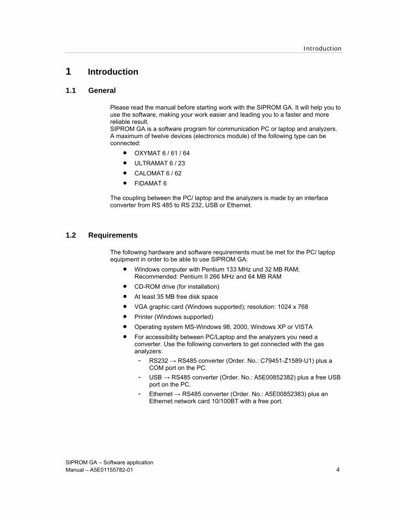
Please read the manual before starting work with the SIPROM GA. It will help you to use the software, making your work easier and leading you to a faster and more reliable result. SIPROM GA is a software program for communication PC or laptop and analyzers. A maximum of twelve devices (electronics module) of the following type can be connected:
• OXYMAT 6 / 61 / 64 • ULTRAMAT 6 / 23 • CALOMAT 6 / 62 • FIDAMAT 6
The coupling between the PC/ laptop and the analyzers is made by an interface converter from RS 485 to RS 232, USB or Ethernet.
1.2 Requirements
The following hardware and software requirements must be met for the PC/ laptop equipment in order to be able to use SIPROM GA:
• Windows computer with Pentium 133 MHz und 32 MB RAM; Recommended: Pentium II 266 MHz and 64 MB RAM
• CD-ROM drive (for installation) • At least 35 MB free disk space • VGA graphic card (Windows supported); resolution: 1024 x 768 • Printer (Windows supported) • Operating system MS-Windows 98, 2000, Windows XP or VISTA • For accessibility between PC/Laptop and the analyzers you need a
converter. Use the following converters to get connected with the gas analyzers: - RS232 → RS485 converter (Order. No.: C79451-Z1589-U1) plus a
COM port on the PC. - USB → RS485 converter (Order. No.: A5E00852382) plus a free USB
port on the PC. - Ethernet → RS485 converter (Order. No.: A5E00852383) plus an
Ethernet network card 10/100BT with a free port.
Introduction
SIPROM GA – Software application Manual – A5E01155782-01 5
1.3 Applications
SIPROM GA offers you a comfortable possibility for controlling your equipment with a PC/laptop. Manual inputs on the device are no longer necessary.
SIPROM GA offers the following functions among other things:
• Display measured values as numeric values in bar diagrams and as curves • Read out diagnostic values (log book, factory data, etc.) • Read out parameters from the device, change and enter (calibration,
parameter, configuration) • Write or load user data in or out of the EEPROM device memory • Monitor gas analysis systems • Download from new device firmware
1.4 Operating levels
The functionality of SIPROM GA is divided into the following operating levels:
Maintenance: includes the possibility of setting up connections with the devices and reading out current device data. Parameters cannot be changed
Specialist: includes all the functions of the maintenance level. plus ... parameters and thus also functions can be changed (according to code levels 1 and 2 on the analyzer)
The operating level is selected at the start of the program. It remains binding up till the end of the program.
Both access authorizations can be protected by separate passwords (see also under [Options > Set password] from page 30).
1.5 Operating modes
SIPROM GA offers the following operating modes:
Online mode: The analyzers are connected. In this setting device parameters can be written in or taken directly from the device.
Offline mode: The analyzers are not connected. It is only possible to parameterize a “virtual” device. The parameter set is saved in a file.
Start Program
SIPROM GA – Software application Manual – A5E01155782-01 6
2 Start Program
2.1 Installation
Follow the next steps for installation of SIPROM GA:
1. Start Windows.
2. Insert the CD „ELAN mode/ SIPROM GA“ The main menu starts automatically.
For starting the main menu manually double click the file index.html.
3. Navigate to menu item ’SIPROM GA Install SIPROM GA’ and start the installation. Follow the installation instructions.
Figure 2-1 Setup Wizard - Siprom GA
4. Confirm the Readme information by clicking 'Next >’.
Figure 2-2 Readme Information

Start Program
SIPROM GA – Software application Manual – A5E01155782-01 7
5. Specify the folder in which the program should get installed.
Figure 2-3 Select folder of installation
6. To define a virtual device in the Offline-Mode you have to parameterise the device and the option boards first. You can redefine the settings later in the program.
Figure 2-4 Define a virtual instrument

Start Program
SIPROM GA – Software application Manual – A5E01155782-01 8
7. Start the installation.
Figure 2-5 Start installation
8. Wait until the installation has finished.
Figure 2-6 Installation is running

Start Program
SIPROM GA – Software application Manual – A5E01155782-01 9
9. Finishing the installation by clicking ‘Finish’.
Figure 2-7 Finish installation
It’s recommended to restart windows after the installation.
Make sure not to use a firewall!
2.2 Configuration
You can start the program after installation.
First you have to configure the network. Navigate to the menu item Options Communication Configuration…
Figure 2-8 Configure and start the communication
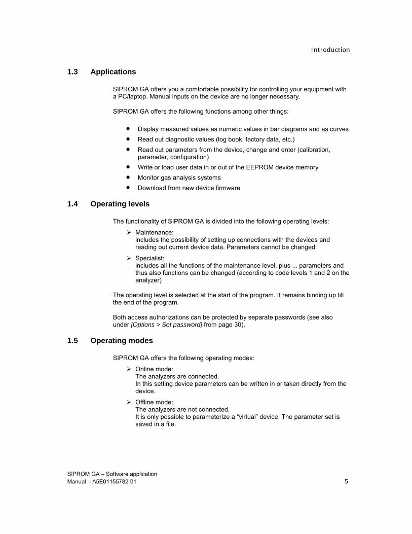
Select the Online-mode and click the button ‘Settings’. Inside the ‘Network settings’ window you can configure max. four nets in one network. The communication get’s initialised by the ‘OK’ button.
Start Program
SIPROM GA – Software application Manual – A5E01155782-01 10
Figure 2-9 Select the operation mode
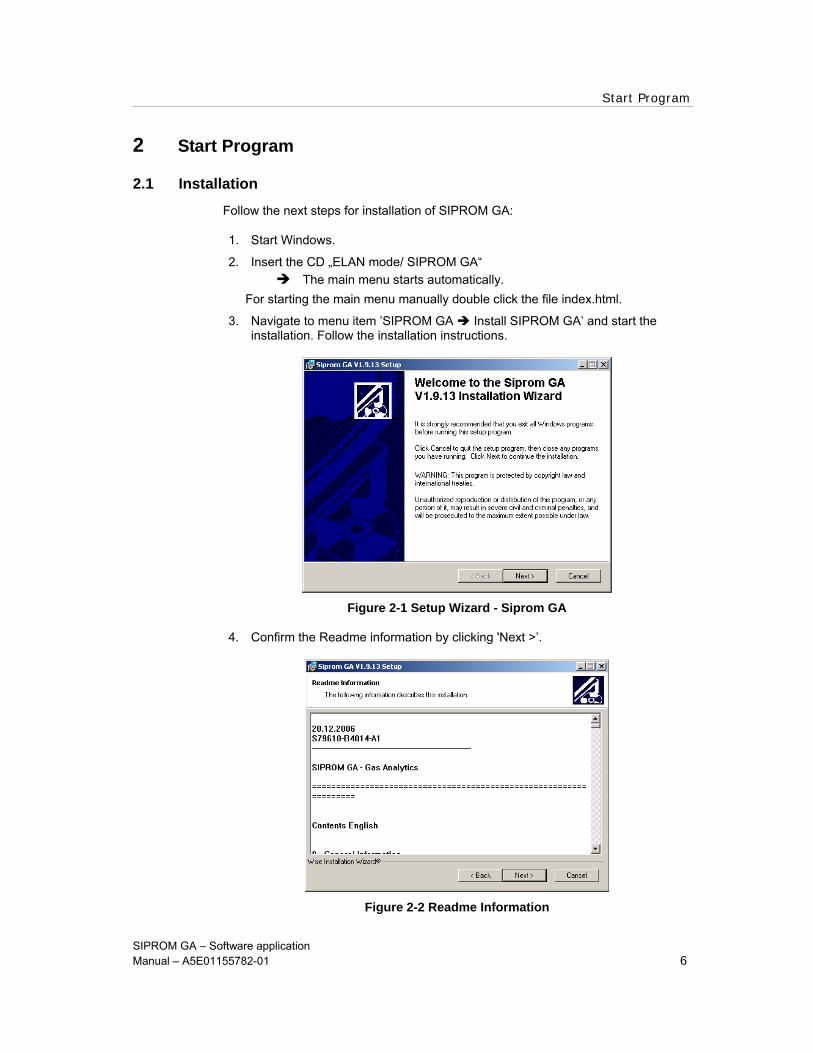
The applied converter with its COM-port act. Virtual COM-port has to be assigned in the network settings window analogical to the ‘COM port Redirector’. Confirm by clicking ‘OK’.
Figure 2-10 Network settings
The addresses of max. 12 devices got scanned. You have to adjust the addresses manually. A doubled address causes a failure which prevents a connection establishment.
Start Program
SIPROM GA – Software application Manual – A5E01155782-01 11
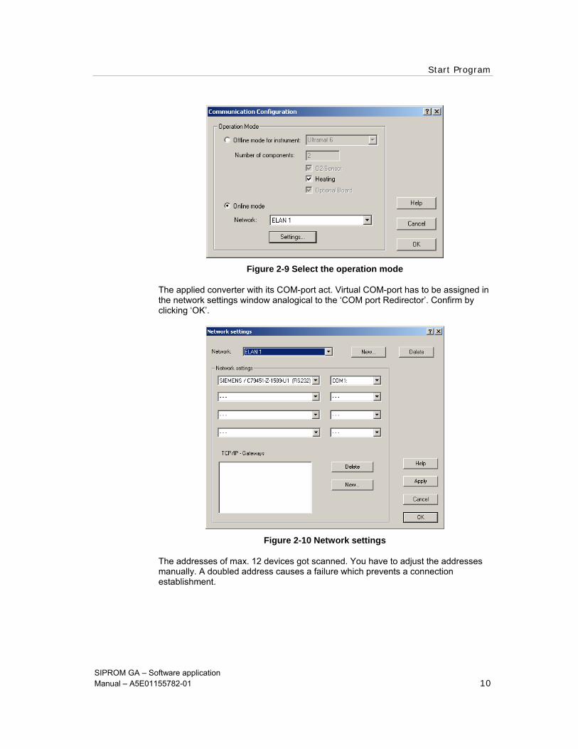
Figure 2-11 Scan the network - ELAN
Please note:
The dialog Communication Configuration can be activated and reconfgured anytime by the menu item Options.
To cancel this dialog or SIPROM GA you have to switch to the ‘Offline mode’!
Notice caption 1.4 for this propos on page 5!
See the attached CD for further information how to install and configure the converters.

Structure of the main window
SIPROM GA – Software application Manual – A5E01155782-01 12
3 Structure of the main window
The main window of the application opens first after starting SIPROM GA. The Online mode or Offline mode is started depending on the program configuration. See chapter 1.5. Operating modes on page 5.
Below the toolbar the largest part of the main window is divided vertically in two. The relative size of the two window sections and the size of the lower section can be changed by moving the cross bar.
On the left hand side of the main window you will find the device tree which contains all the available devices.
As soon as a device has been selected, the corresponding data appear on the right hand side of the main window.
Figure 3-1 Structure of the main window
After initialization the device tree is built automatically based on the physical circumstances in the online mode. The devices are sorted according to addresses (channel numbers). Each channel number may only be assigned once. Otherwise a fault message appears.
In offline mode the tree only contains a “virtual device”. The type of virtual device (ULTRAMAT 6 , OXYMAT 6 ...) is defined at the start of the program or when changing to offline mode.
Device tree
Structure of the main window
SIPROM GA – Software application Manual – A5E01155782-01 13
In online mode, digital measurement data are displayed in the right part of the main window. The type of display depends on the selection in the device tree. The following data can be displayed:
device (describes the device status)
component (displays the selected component)
current value (specified in ppm)
state (indicates whether operating modes were selected)
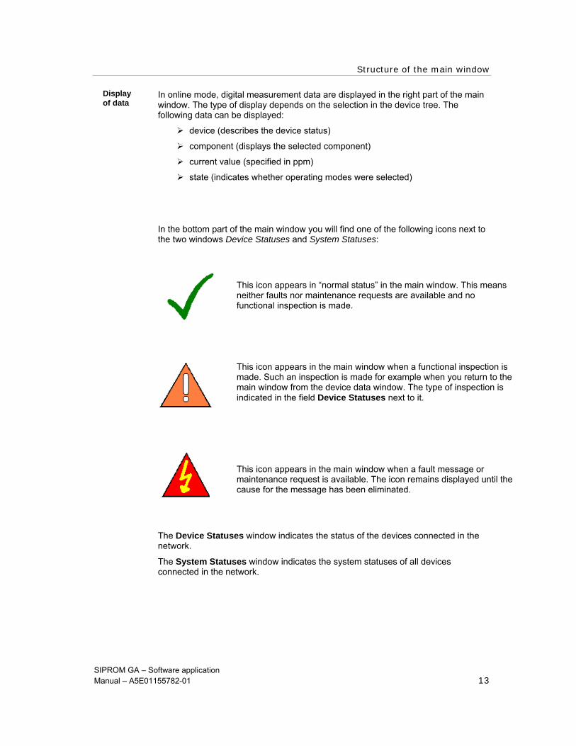
In the bottom part of the main window you will find one of the following icons next to the two windows Device Statuses and System Statuses:
The Device Statuses window indicates the status of the devices connected in the network.
The System Statuses window indicates the system statuses of all devices connected in the network.
This icon appears in “normal status” in the main window. This means neither faults nor maintenance requests are available and no functional inspection is made. This icon appears in the main window when a functional inspection is made. Such an inspection is made for example when you return to the main window from the device data window. The type of inspection is indicated in the field Device Statuses next to it. This icon appears in the main window when a fault message or maintenance request is available. The icon remains displayed until the cause for the message has been eliminated.
Display of data
Structure of the main window
SIPROM GA – Software application Manual – A5E01155782-01 14
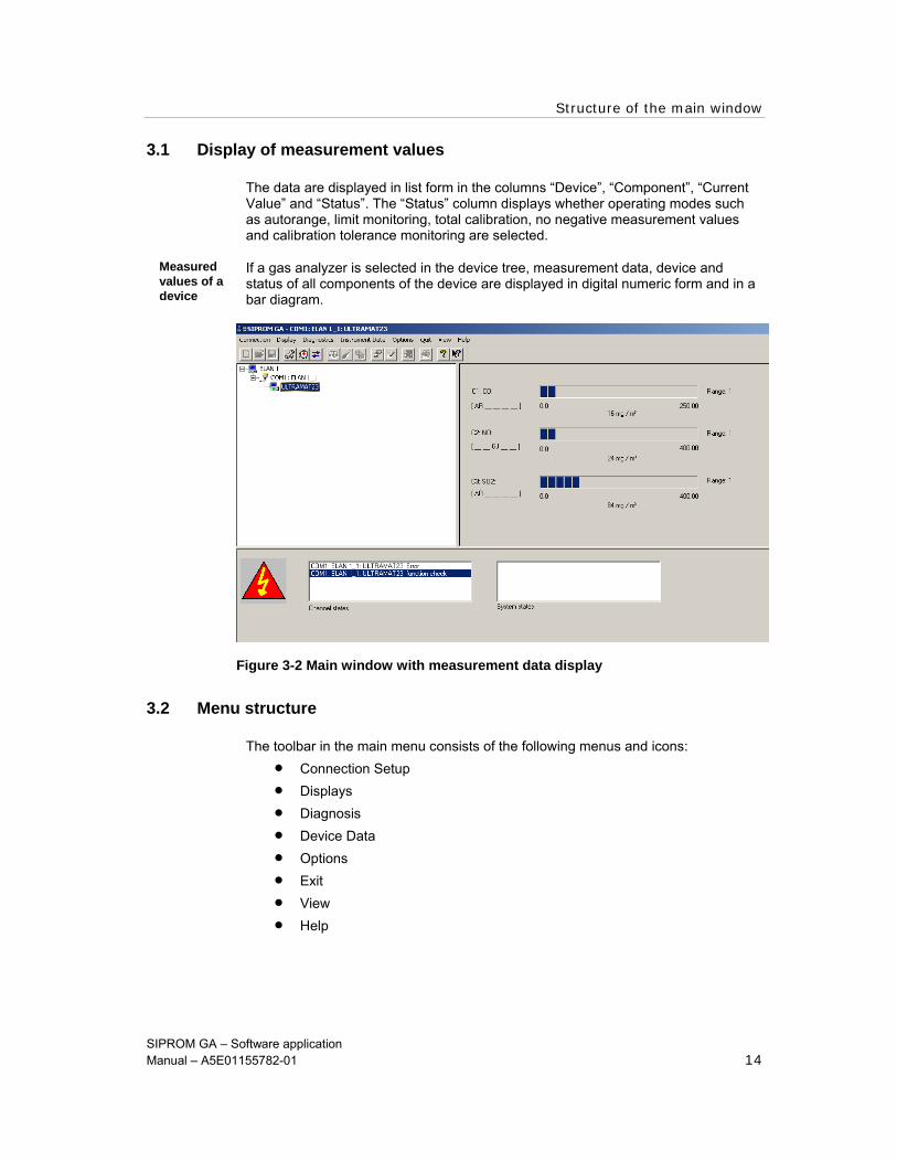
3.1 Display of measurement values
The data are displayed in list form in the columns “Device”, “Component”, “Current Value” and “Status”. The “Status” column displays whether operating modes such as autorange, limit monitoring, total calibration, no negative measurement values and calibration tolerance monitoring are selected.
If a gas analyzer is selected in the device tree, measurement data, device and status of all components of the device are displayed in digital numeric form and in a bar diagram.
3.2 Menu structure
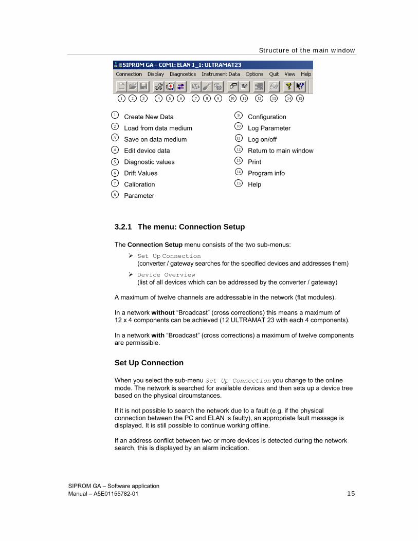
The toolbar in the main menu consists of the following menus and icons: • Connection Setup • Displays • Diagnosis • Device Data • Options • Exit • View • Help
Measured values of a device
Figure 3-2 Main window with measurement data display
Structure of the main window
SIPROM GA – Software application Manual – A5E01155782-01 15
3.2.1 The menu: Connection Setup
The Connection Setup menu consists of the two sub-menus:
Set Up Connection (converter / gateway searches for the specified devices and addresses them)
Device Overview (list of all devices which can be addressed by the converter / gateway)
A maximum of twelve channels are addressable in the network (flat modules).
In a network without “Broadcast” (cross corrections) this means a maximum of 12 x 4 components can be achieved (12 ULTRAMAT 23 with each 4 components).
In a network with “Broadcast” (cross corrections) a maximum of twelve components are permissible.
Set Up Connection
When you select the sub-menu Set Up Connection you change to the online mode. The network is searched for available devices and then sets up a device tree based on the physical circumstances.
If it is not possible to search the network due to a fault (e.g. if the physical connection between the PC and ELAN is faulty), an appropriate fault message is displayed. It is still possible to continue working offline.
If an address conflict between two or more devices is detected during the network search, this is displayed by an alarm indication.
Create New Data Configuration
Load from data medium Log Parameter
Save on data medium Log on/off
Edit device data Return to main window
Diagnostic values Print
Drift Values Program info
Calibration Help
Parameter
10
9
12
13
11
15
1
7
6
5
4
3
2
14
8
1 2 3 4 5 6 7 8 9 10 11 12 13 14 15

Structure of the main window
16 Handbuch SIPROM GA
After eliminating the address conflict, the connection must be set up again by selecting this sub-menu.
Structure of the main window
SIPROM GA – Software application Manual – A5E01155782-01 17
Device Overview
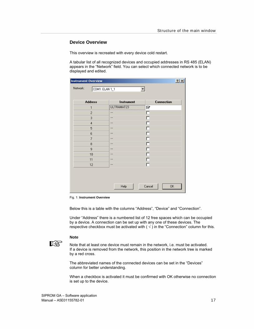
This overview is recreated with every device cold restart.
A tabular list of all recognized devices and occupied addresses in RS 485 (ELAN) appears in the “Network” field. You can select which connected network is to be displayed and edited.
Fig. 1: Instrument Overview
Below this is a table with the columns “Address”, “Device” and “Connection”.
Under “Address” there is a numbered list of 12 free spaces which can be occupied by a device. A connection can be set up with any one of these devices. The respective checkbox must be activated with ( √ ) in the “Connection” column for this.
Note
Note that at least one device must remain in the network, i.e. must be activated. If a device is removed from the network, this position in the network tree is marked by a red cross.
The abbreviated names of the connected devices can be set in the “Devices” column for better understanding.
When a checkbox is activated it must be confirmed with OK otherwise no connection is set up to the device.

Structure of the main window
SIPROM GA – Software application Manual – A5E01155782-01 18
3.2.2 The menu: Displays
The Displays menu consists of the following three sub-menus: • Curve Display
• Log Parameter
• Log Measurement Values (start / stop logging)
At least one analyzer must be selected and activated under [Displays > Log Parameter > Device (tab)]. Otherwise neither measurement values can be logged not a curve displayed. An appropriate message appears.
Curve display
In the Curve Display sub-menu parameters can be adapted which change the display of the curve.
Prerequisite In order to change the curve display you must be working in the online mode.
The sub-menu consists of the two tabs:
Curve
Settings
Figure 3-3 Curve View
Structure of the main window
SIPROM GA – Software application Manual – A5E01155782-01 19
At least one device must be selected first in the Settings tab to get the graph view of the measurement values. A maximum of 4 measured values of all the devices in online mode can be displayed in one diagram.
The display can be saved and transferred to another file with the EXPORT button. The measurement value display can be printed directly with the PRINT button. Various settings are possible for this in the specialist level.
Note
You go to the usual Microsoft print dialog. Also observe the PROPERTIES buttong to make additional settings. The print output can be set additionally. With the “Screen” option you first get a preview of the page to be printed. With the toolbar you can maximize details or print the whole page. Here too you go to the usual Microsoft print dialog.
Tab Curve
Structure of the main window
SIPROM GA – Software application Manual – A5E01155782A-01 20
An analyzer must be selected in the Settings tab before a graphic appears in the Curve tab. The following parameters can be specified to change the display type and appearance of the curve:
Display time period: Maximum displayed time period in hours and minutes, the x axis is adapted to the appropriate time
Scroll range of the X axis in % : The measurement value runs along the x axis to the end of the displayed range (predefined under “displayed time period”). Then the x axis is shifted 100 – x% value. E.g. the X axis is shifted 70 % to the left with an entered value of 30%. 30% of the measurement value remains displayed. This gives a continuous display.
Display current measurement value in legend: Setting whether the current measurement value is to be entered in the legend
Legend: Selection of the position of a legend
The following curve-specific details can also be changed:
Curve: Possibility to choose between different curves with different attributes (color, icon).
Network: Selection of the ELAN network from which a device can be selected.
Component: Selection which component is to be displayed as a curve in reference to the device.
Color: Selection of the curve color.
Note: Some of these cannot be displayed in a 256 color matrix!
Icon: A curve can also be identified by icons in addition to by colors.
Upper limit: Greatest displayable measurement value; Y axis
Lower limit: Smallest displayable measurement value; Y axis
Grid: Grid lines can be displayed
Show zero line; adjustment zero: The entered value serves as an optical limit if the measurement value fluctuates in this range.
Tab Settings
Structure of the main window
SIPROM GA – Software application Manual – A5E01155782A-01 21
Note
The inputs are only considered in the curve display when you press the ACCEPT button.
Log parameter
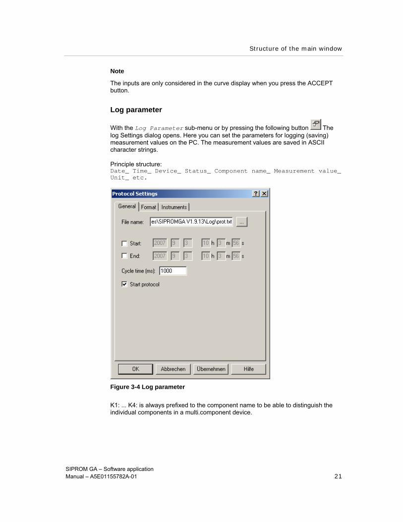
With the Log Parameter sub-menu or by pressing the following button The log Settings dialog opens. Here you can set the parameters for logging (saving) measurement values on the PC. The measurement values are saved in ASCII character strings.
Principle structure: Date_ Time_ Device_ Status_ Component name_ Measurement value_ Unit_ etc.
Figure 3-4 Log parameter
K1: ... K4: is always prefixed to the component name to be able to distinguish the individual components in a multi.component device.

Structure of the main window
SIPROM GA – Software application Manual – A5E01155782A-01 22
General This tab contains general data for creating logs. The following data can be set:
File name: A name for the log file can be assigned in the input field. You go to the file selection dialog by pressing the “ ... ” button
Beginning / end: The measurement value logging can take place time controlled. After activating the checkbox the date and time can be specified in hours : minutes : seconds. Both values can be activated/ deactivated immediately
Cycle time: Time interval in milliseconds between the individual measurement value sets to be logged
Start log: The checkbox must be activated to start logging
Tab Format The format properties of the log can be defined in this tab. Not all inputs are possible
in every device:
Number of columns: Log layout is divided into columns
Ring buffer with: not integrated as standard
File splitting according to: After the specified number of lines the logging is continued in a new file. The files are numbered consecutively. This function avoids loss of files when the PC fails.
Separating character: Separating character: The separating character of the individual columns can be set here. The current country-specific setting appears in a message on the PC.
This tab lists all devices of which the measurement values can be logged. Each device can be selected individually. The following factors can also be influenced:
Decimal character: Selectable character between decimal numbers
Network: A network can be selected with the IP number. By activating / deactivating the checkbox, you can decide which devices the log settings are to be transferred to.
Note
The inputs are only considered for logging when you press the ACCEPT button.
Tab Device

Structure of the main window
SIPROM GA – Software application Manual – A5E01155782A-01 23
Logging measurement values
With the Log Measurement Values sub-menu you can start or stop saving measurement values. All the measurement values in the network can be saved on hard disk.
Prerequisite: To activate this sub-menu you must have selected and activated at least one analyzer under [Displays > Log Parameter > Device first. Otherwise an appropriate message appears.
The following settings are made in a dialog at the beginning of measurement value logging:
- Location and name of the log file - Selection of the devices of which the measurement values are to be logged - Determination of the sample rate: please bear iln mind that the minimum time is
calculated from the number of available devices - Maximum number of lines per file: The name of the log file is extended by a
counter. As soon as the file has reached the maximum number of lines, it is closed and a new file of the same name with an appropriate counter is created.
The data format can be read by common evaluation programs (e.g.. Text Editor/ Import to MS-Excel) The following are saved per unit of time: Date/time/device/status/component name/concentration/unit/device 2.
3.2.3 The menu: Diagnosis
Diagnostic Values
Selection of the Diagnostic Values sub-menu or the following button opens the Diagnostic Values dialog. The following tabs can be activated:
• Device Status • Components • Pressure, Temperatures • Factory Data
Prerequisite These tabs are only active when working in online mode and when a gas analyzer is selected iln the device tree. Every tab can be printed separately.
An entry must be selected first in the log book before it can be acknowledged. With “Log Book Update” the list of log book entries is read out of the device again.
The diagnostic values can also be printed.
Structure of the main window
SIPROM GA – Software application Manual – A5E01155782A-01 24
The tab Device Status is divided into the following two sections:
Log book
Calibration deviation
Log book:
This table shows all logged fault messages and maintenance requests. Each message only appears once in the log book.
A maintenance request is released when the parameter values reach their limits. However, the device is still capable of measuring (e.g. AUTOCAL deviation). In addition limit alarms are registered but they do not trigger a maintenance request or a fault message.
Per entry it is indicated when the message arrived (incoming) or left (deleted/eliminated). The log book may contain a maximum of 32 messages. It works according to the principle of the cyclic buffer, i.e. when all 32 places are occupied, the oldest message is overwritten.
The data are read directly from the device with the UPDATE LOG BOOK button.
The stored fault message/maintenance request is deleted with the ACKNOWLEDGE button. However, it should only be deleted if the cause has been eliminated.
Tab Device Status

Structure of the main window
SIPROM GA – Software application Manual – A5E01155782A-01 25
Note
The cause of the message is not eliminated by deleting with the ACKNOWLEDGE button! After a short time the alarm reappears and must be eliminated.
With the PRINT button you go to the Print Output dialog. See also chapter 3.2.2. Curve display
Figure 3-5 Diagnostic values
Calibration deviations:
The following data can be read out:
Zero drift: This dialog shows the deviation of 0.0 between zero calibration and adjustment zero
Zero drift maximum: Maximum value of drift. A maintenance request is released in case of greater drifts
Nominal value deviations: This dialog shows the deviation from the nominal value of the test gas for every component between two calibration processes; for O2 this deviation is formed with every AUTOCAL
Nominal value deviations maximum: Displays the permissible greatest value of deviation. A maintenance request is released in case of greater deviations
adjustment zero: Maximum adjustment possibility in adjustment zero are 100%; this setting has no function in the ULTRAMAT 23
Structure of the main window
SIPROM GA – Software application Manual – A5E01155782A-01 26
Tab Component The measurement value, the current measuring range and the corresponding value
of the analog output in microampere are displayed for all available components. With the PRINT button you go to the Print Output dialog. See also chapter 3.2.2. Curve Display.
Tab Pressure, Temperature The most important measuring variables and their measurement values are listed in
this tab.
The data vary because they refer to different devices. For example the ULTRAMAT 6 has the chopper frequency value which the CALOMAT 6 does not.
Tab Factory data The Factory Data tab lists the data which are fixed by SIEMENS before the device
leaves the factory. They serve for identifying and determining the scope of functions of the device such as the factory number. A distinction is also made between hardware and software data. These data cannot be change either in the Maintenance or Specialist level. They are read only data.
3.2.4 The menu: Device Data
Edit Device Data After selecting the Edit Device Data sub-menu or the following
button the device data window opens. This enables the parameter assignment of a gas analyzer. See from chapter 3. Menu structure of the device data window.
3.2.5 The menu: Options
The menu Options contains different settings for different topics. The sub-menus are subdivided as follows:
• Configure Program
• Configure Printer
• Print Templates
• Configure Communication
• Set Password
Configure Program
After selecting the Configure Program sub-menu the Program Settings dialog opens. This dialog contains both tabs:
Program Start
General
Structure of the main window
SIPROM GA – Software application Manual – A5E01155782A-01 27
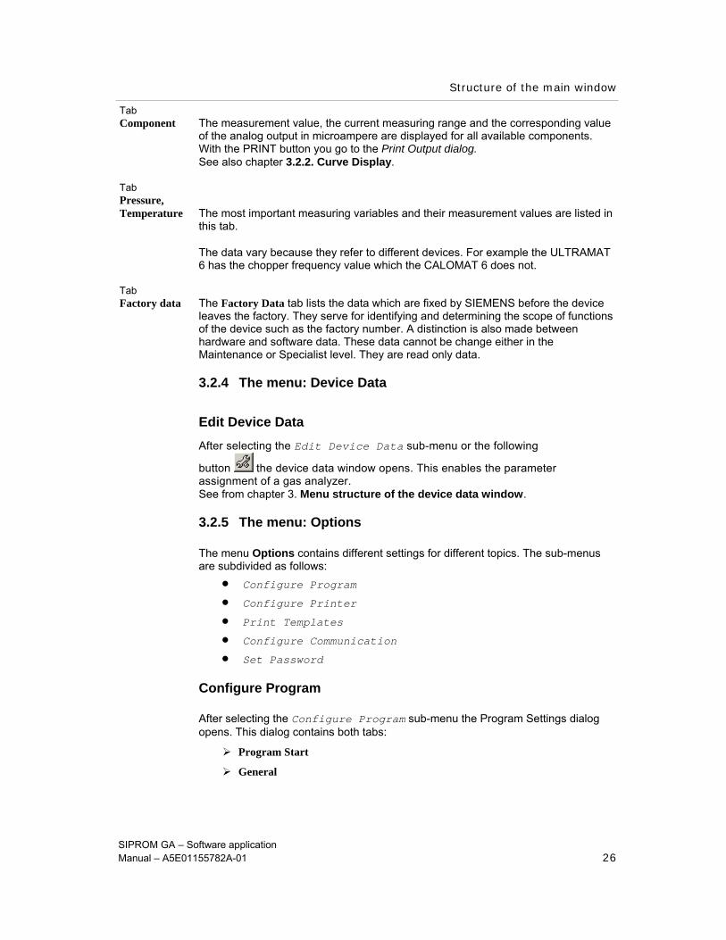
Tab Program Start In the Program Start tab you can select which devices are to be started in online
and which in offline mode. Only one device type can be set at a time whereby it is possible to enter the number of components additionally here. If different device types are to be set, the dialog must be called several times.
Figure 3-6 Program configuration
The O2-PROBE button can only be activated in the ULTRAMAT 23 and tells you whether or not there is a probe in the device.
The HEATING button can only be activated in the ULTRAMAT 6, OXYMAT 6 and the CALOMAT 62 and like the OPTION MODULE button tells you whether or not a heating or option module is available.
If the “Offline” checkbox is checked the inputs must be confirmed with the ACCEPT button.
If, however, the online mode is selected, the program automatically sets up a connection after starting. The most recently active network profile is used here.
The General tab allows you to enter a name for the project, the company and the department. This information appears on the paper when you print out the most important parameters and in the curve display.
Configure Printer
After selecting the Configure Printer sub-menu a printer can be selected and set. Standard Windows dialogs are used for this.
The printer connection can be set up using the NETWORK button.
Also observe the PROPERTIES button to male further settings such as double page printing or similar.
Tab General

Structure of the main window
SIPROM GA – Software application Manual – A5E01155782A-01 28
Printing Templates
In the Printing Templates sub-menu you can edit the printing templates for the analog measurement value display and output of device parameters.
Prerequisite The Specialist level has been selected in the Start menu.
Three different printing templates are available for selection by double clicking: • Diagnostic Values • Diagrams • List of Parameters.
After selecting one of these templates a dialog opens which has its own menu and toolbar. You can make different settings with respect to the appearance and functionality with these functions. Different printer settings and filters are possible.
This separate dialog also contains an online help system.
Configure Communication
Under the Configure Communication sub-menu the Communication Configuration dialog is started. This dialog also appears with every cold restart of SIPROM GA. You can select which devices are to be started in offline mode.
If different device types are to be set, the dialog must be called several times because only one device type can be set at a time.
You can predefine how many components the device is to have in the “Number of Components” field. In the ULTRAMAT 23 you can predefine additionally whether there is to be an O2 probe in the offline mode. There is a possibility of a heating in ULTRAMAT 6, OXYMAT 6 and CALOMAT 62.
In all devices you can predefined whether an option module is to be provided.
If the online mode checkbox is activated on the other hand, you can choose between the configured network profiles.
Structure of the main window
SIPROM GA – Software application Manual – A5E01155782A-01 29
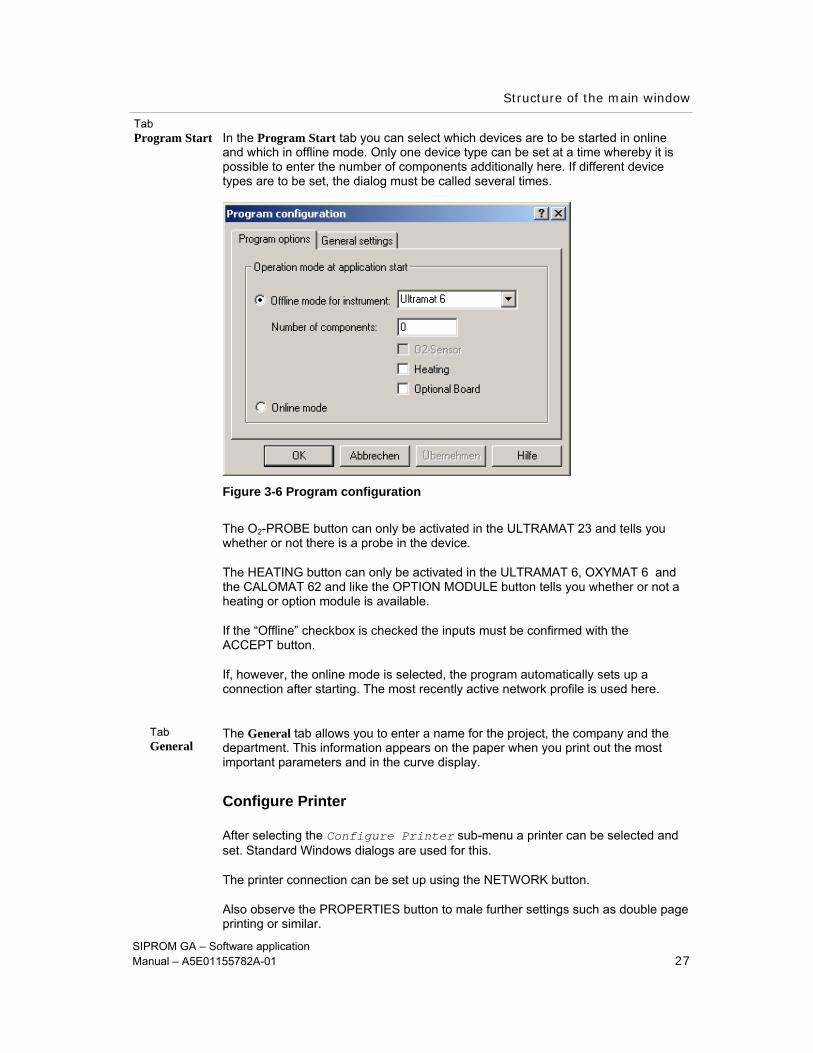
Figure 3-7 Communication Configuration
With the SETTINGS button you go to the Network Settings dialog.
A new network can be set or an old one deleted with the NEW/DELETE buttons.
Under Network settings the connected converters and their COM-Port are selected.
Figure 3-8 Network settings

Structure of the main window
SIPROM GA – Software application Manual – A5E01155782A-01 30
Set Password
It is possible to assign passwords for the Specialist and Maintenance levels to ensure only certain persons have access to the device(s).
A new password can be assigned after entering the old one. For security the new password must be repeated in the field below.
Figure 3-9 Set Password
3.2.6 The menu: Exit
Exit program
SIPROM GA is exited after a security prompt under the Exit Program sub-menu. Existing connections to analyzers are disconnected.
Changes made in the offline mode carry references which allow these data to be saved.
Structure of the main window
SIPROM GA – Software application Manual – A5E01155782A-01 31
3.2.7 The menu: View
With the View menu both the status bar and the toolbar can be shown/hidden.
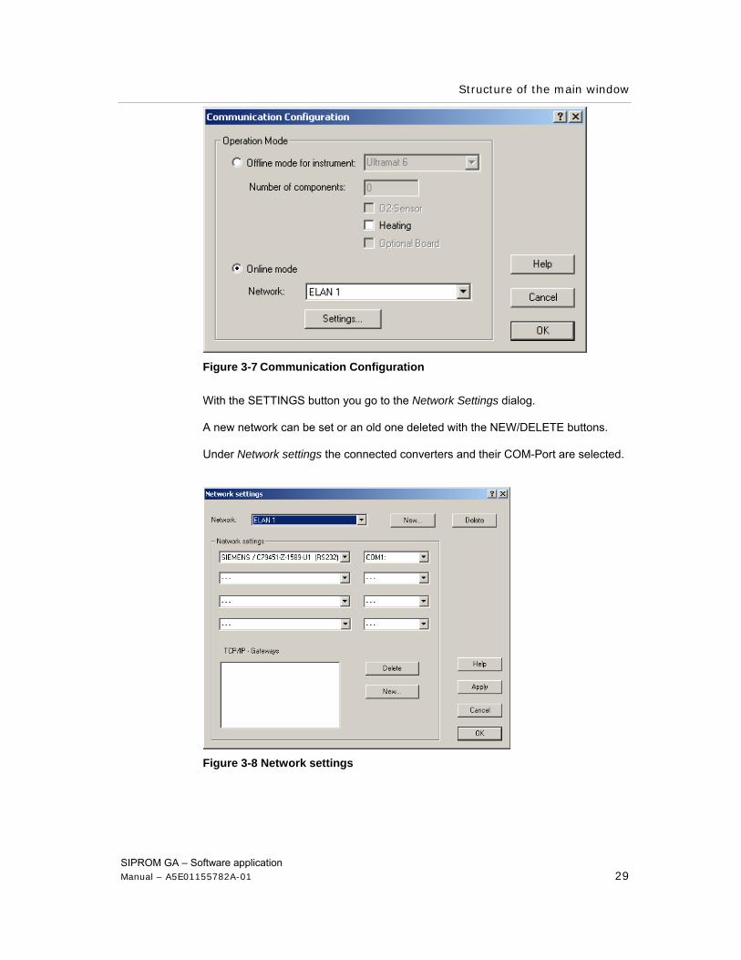
Toolbar All control icons for the main window, including the help icons are displayed. If the cursor is kept on an icon for longer than 2 seconds, its function is displayed.
Status bar: The following values appear here:
Offline / Online
Specialist / Maintenance
Date and time
Name of the selected device with status (Measure / Calibrate)
Remote status
Error status (ERR)
Functional inspection (CTRL)
Maintenance request (MAIN)
Limit value (LIM)
Measurement value logging on (LOG).
Create New Data Configuration
Load from data medium Log Parameter
Save on data medium Log on/off
Edit device data Return to main window
Diagnostic values Print
Drift Values Program info
Calibration Help
Parameter
10
9
12
13
11
15
1
7
6
5
4
3
2
14
8
1 2 3 4 5 6 7 8 9 10 11 12 13 14 15
Structure of the main window
SIPROM GA – Software application Manual – A5E01155782A-01 32
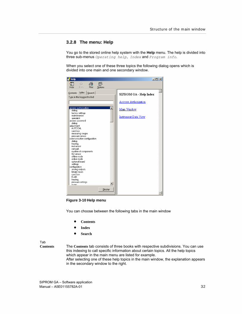
3.2.8 The menu: Help
You go to the stored online help system with the Help menu. The help is divided into three sub-menus Operating help, Index and Program info.
When you select one of these three topics the following dialog opens which is divided into one main and one secondary window.
Figure 3-10 Help menu
You can choose between the following tabs in the main window
• Contents • Index • Search
Tab Contents The Contents tab consists of three books with respective subdivisions. You can use
this indexing to call specific information about certain topics. All the help topics which appear in the main menu are listed for example. After selecting one of these help topics in the main window, the explanation appears in the secondary window to the right.
Structure of the main window
SIPROM GA – Software application Manual – A5E01155782A-01 33
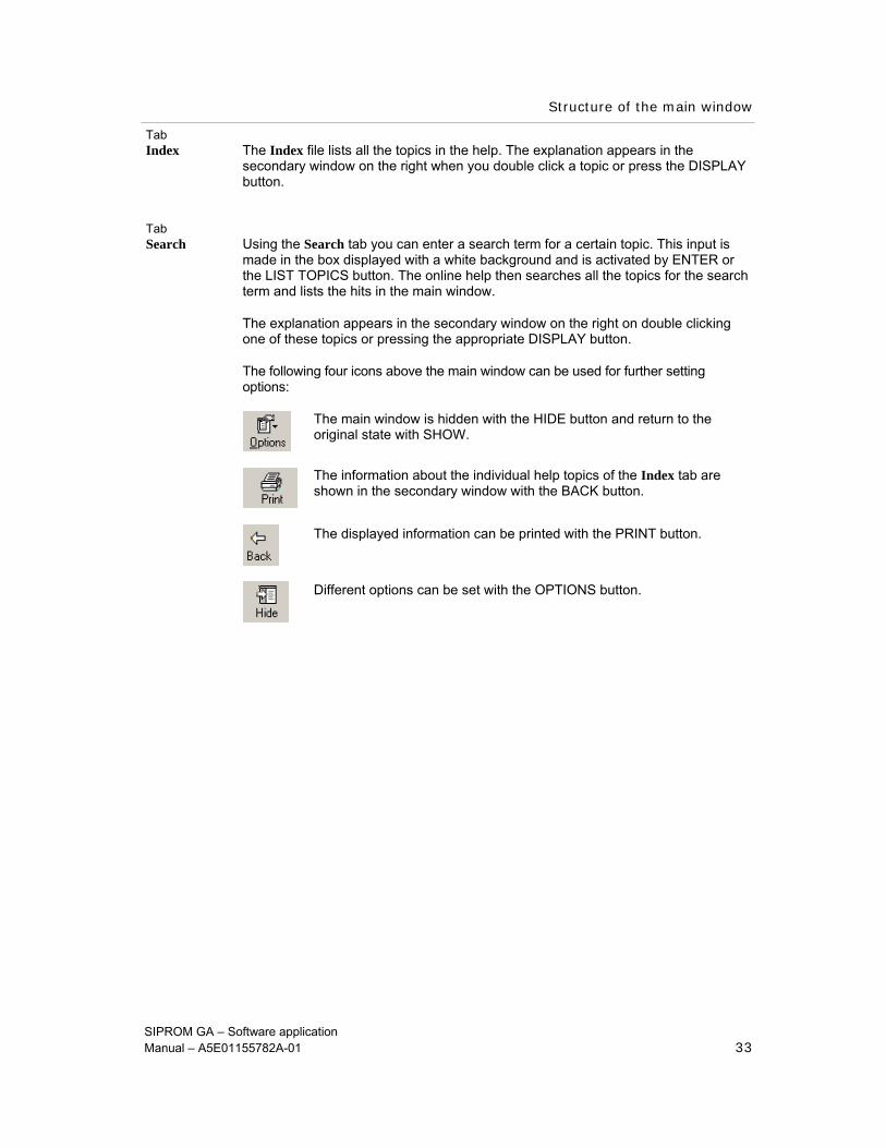
Tab Index The Index file lists all the topics in the help. The explanation appears in the
secondary window on the right when you double click a topic or press the DISPLAY button.
Tab Search Using the Search tab you can enter a search term for a certain topic. This input is
made in the box displayed with a white background and is activated by ENTER or the LIST TOPICS button. The online help then searches all the topics for the search term and lists the hits in the main window.
The explanation appears in the secondary window on the right on double clicking one of these topics or pressing the appropriate DISPLAY button.
The following four icons above the main window can be used for further setting options:
The main window is hidden with the HIDE button and return to the original state with SHOW. The information about the individual help topics of the Index tab are shown in the secondary window with the BACK button. The displayed information can be printed with the PRINT button.
Different options can be set with the OPTIONS button.
Device data window
SIPROM GA – Software application Manual – A5E01155782A-01 34
4 Device data window Under the Device Data menu, the Edit Device Data sub-menu can be selected.
The device data window opens
Prerequisite A gas analyzer must be selected in the main window.
The functions of the device data window are exclusively available in the Specialist level. In the Maintenance level all the device data can be read but not changed.
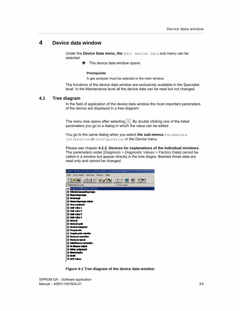
4.1 Tree diagram In the field of application of the device data window the most important parameters of the device are displayed in a tree diagram:
The menu tree opens after selecting + . By double clicking one of the listed parameters you go to a dialog in which the value can be edited.
You go to the same dialog when you select the sub-menus Parameters, Calibration or Configuration in the Device menu.
Please see chapter 4.2.2. Devices for explanations of the individual windows. The parameters under [Diagnosis > Diagnostic Values > Factory Data] cannot be called in a window but appear directly in the tree diagra. Besides these data are read only and cannot be changed.
Figure 4-1 Tree diagram of the device data window

Device data window
SIPROM GA – Software application Manual – A5E01155782A-01 35

Device data window
SIPROM GA – Software application Manual – A5E01155782A-01 36
4.2 Menu Structure
SIPROM GA does not validate the entered values. The entered values are passed on directly to the device. Handling faulty values is the responsibility of the device firmware. If the device delivers an error as a reply, this error is displayed on screen.
Pressing the ACCEPT or OK button in the tabs causes all values visible on the relevant tab to be transferred to the device one after another. As a rule several ELAN commands are necessary to transfer all values.
If a command fails the fault message is displayed and transfer of the values is aborted at this point.
The CANCEL button only cancels the last entries. Values which have already been transferred to the device with the ACCEPT button are not reset to their original value.
The toolbar of the device data window consists of the following sub-menus: • Data medium
• Devices
• Services
• Back
• Help
The toolbar contains the following icons:
Create New Data Configuration
Load from data medium Log Parameter
Save on data medium Log on/off
Edit device data Return to main window
Diagnostic Values Print
Calibration Program info
Adjustment Help
Parameter
4.2.1 The menu: Data Medium
In the Data Medium menu pertaining either to the data medium or the data in general The following sub-menus can be called:
• Load from data medium
• Save to data medium
• Save to data medium as
• Create New Data
157
8
1
6
5
4
3
2
9
10
11
12
13
14
1 2 3 4 5 6 7 8 9 10 11 12 13 14 15
Device data window
SIPROM GA – Software application Manual – A5E01155782A-01 37
Load from data medium
After selecting the Load from data medium sub-menu the message appears on the screen that the online mode is not exited. This results in the device switching automatically to the offline mode.
It is possible to load a parameter set for an analyzer from disk or hard disk. After loading a parameter set the device goes into offline mode. When new data are created the device type and number of components is requested.
Save to data medium
With the Save to data medium sub-menu you can save the current device settings in a file on disk or hard disk.
The device remains in the corresponding online / offline mode.
Save on data medium as
Using the Save on data medium as sub-menu the current device settings can be saved in a file on disk or hard disk under a new name.
The device remains in the corresponding online/offline mode.
Create New Data
After selecting the Create New Data sub-menu a list of available device types is output.
After a device type has been selected, a change is made in the offline mode. A parameter set of a “virtual device” of the selected type can then be edited.
Device data window
SIPROM GA – Software application Manual – A5E01155782A-01 38
4.2.2 The menu: Device
Device-specific data can be changed, loaded or saved under the Device menu. The following sub-menus can be called:
• Calibration
• Parameter
• Configuration
• Load PC data
• Save PC data
• Load user data
• Save user data
• Load factory data
• Reset
Calibration
After selecting the Calibration sub-menu or the following button the Calibration dialog opens. It contains the following tabs:
• Measuring Ranges • Pressure Sensor • AUTOCAL
Changes in the tabs are transferred directly to the device with the ACCEPT button and then OK.

Device data window
SIPROM GA – Software application Manual – A5E01155782A-01 39
Figure 4-2 Adjustment
Tab Measuring Under “Components” it is possible to adjust zero and, with the help of one or more Range test gases, the IR channels and to reset the sensitivity.
The columns “Adjustment zero” and “set point MB x” contain an input field for every components and a button which triggers the calibration.
The total calibration for every component is switched on or off in the checkbox for “Total calibration”.
In a total calibration the sensitivity for the selected measuring range is harmonized. The calibration is adopted for the other measuring ranges and the selected measuring range becomes the leading measuring range. It is advisable to select the greatest measuring range for this.
If total calibration is not activated a single calibration is made. The sensitivity for every measuring range is harmonized individually.
Device Components Measuring ranges
OXYMAT 6 / 61 / 64 1 MB 1-MB 4
ULTRAMAT 6 max. 2 MB 1-MB 4
ULTRAMAT 23 max. 3 + poss. O2-probe only MB 1-MB 2
CALOMAT 6 / 62 1 MB 1-MB 4
FIDAMAT 6 1 MB 1-MB 4 In ULTRAMAT 6 with several components only a total calibration is possible.

Device data window
SIPROM GA – Software application Manual – A5E01155782A-01 40
Tab Pressure sensor With this tab it is possible to calibrate the internal pressure sensor. The current
pressure in hPa is specified under “Measurement Value”. The set point of the pressure sensor can be re-entered. A comparative value of e.g. as accurate as possible a barometer must be entered. Then the action is triggered with the “Calibrate” button.
Tab AUTOCAL Settings in this tab depend on device and option card.
The following settings can be made:
AUTOCAL/- Check on In the off state the cycle time continues running. However, no automatic calibration
is triggered. ULTRAMAT 23: This setting is irrelevant for this device.
AUTOCAL Start An AUTOCAL is triggered with this button. AUTOCAL- Check start An AUTOCAL-Check is triggered with this button. Next AUTO- CAL-Check in The next AUTOCAL or AUTOCAL-Check will be performed automatically by the
device after the specified time.
Cycle time The cycle time is the time between two AUTOCAL processes triggered by the device. AUTOCAL triggering is suppressed by a binary input with the button. The definition of a binary input for AUTOCAL triggering sets the cycle time to 0 (cycle stop). No cyclic AUTOCAL is performed at a setting of 0 hours. ULTRAMAT 23: If the device is used in systems of TA Luft and BimSch V the cycle time may not be set > 6 h.
Start by An AUTOCAL can be triggered by a binary input or a cycle parameter. Different values can be selected on activating the “Cycle” checkbox. In the last window you can select whether an AUTOCAL or an AUTOCAL-Check is to be performed.
Calibration tolerances Values for the calibration tolerance at adjustment zero or the sensitivity can be
entered here.
Run Gives an overview of the gas purge phases in AUTOCAL. After selecting the line, the appropriate run time / purge time can be changed.
Device data window
SIPROM GA – Software application Manual – A5E01155782A-01 41
Run stages One of offered functions can be selected under the list. Proceed as follows:
1. Select the function with a mouse click
2. Select a function from the list and assign it to the desired function with the << key.
Note
“free” must be assigned to delete a stage.
3. Enter the desired duration in the Run time field after selecting the run stage.
The following run stages can be selected for the devices. Up to 12 stages can be combined in any order.
• zero gas1, zero gas 2 • tracer gas 1, tracer gas 2, tracer gas 3, tracer gas 4 • measuring gas purge • measuring gas intermediate operation • message contact • free
ULTRAMAT 23: There are two run stages here “zero gas” and “measuring gas purge”. These settings cannot be changed. Run time: The appropriate run time/purge time can be set after selecting the line. The purge time can be assigned after a change with the << key. Parameter
After selecting the Parameter sub-menu or the following button the Parameter dialog opens. There are up to eight tabs (depending on the device type). Changes in the tabs are transferred directly to the device with the OK button or the ACCEPT button.
Device data window
SIPROM GA – Software application Manual – A5E01155782A-01 42
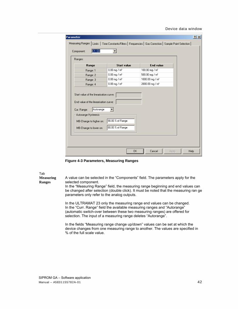
Figure 4-3 Parameters, Measuring Ranges
Tab Measuring A value can be selected in the “Components” field. The parameters apply for the Ranges selected component.
In the “Measuring Range” field, the measuring range beginning and end values can be changed after selection (double click). It must be noted that the measuring ran ge parameters only refer to the analog outputs. In the ULTRAMAT 23 only the measuring range end values can be changed. In the “Curr. Range” field the available measuring ranges and “Autorange” (automatic switch-over between these two measuring ranges) are offered for selection. The input of a measuring range deletes “Autorange”. In the fields “Measuring range change up/down” values can be set at which the device changes from one measuring range to another. The values are specified in % of the full scale value.

Device data window
SIPROM GA – Software application Manual – A5E01155782A-01 43
Tab Limit values Every measurement component is assigned four, the ULTRAMAT 23 only two limit
values. For two limit values, the settings “Value”, “message at”, “Valid in measuring range” can be made and the field “off” activated or deactivated. On dropping below/exceeding the four or two limit values a relay responds providing the appropriate limit signaling has been allocated to a relay. For every measuring range the value, direction of effect of the valie measuring ranges one and two (exceed/drop below) and the general release (on/ off) can be entered separately.
Tab Time Constants/Filters Time constants Different time constants can be set for the selected component for noise
suppression of the measurement value signal. The time constant “T 90 inside” is active within an interval to be parameterized the thresholds of which are defined in percent of the smallest measuring range. On the one hand it suppresses slight signal changes (e.g. electrical noise) but becomes immediately ineffective as soon as the signal exceeds a threshold value. When that happens the signal is suppressed by the time constant “T90 outside” until it drops back below the threshold value. Then “T90 inside” becomes active again.
Filter for fault value sup- pression This option is not selectable for ULTRAMAT 23.
The measurement value changes in this time interval are interpreted as fault signals and suppressed with a time filter.
Tab Frequecies This option is only selectable for ULTRAMAT 6 and OXYMAT 6.
Normally the chopper frequency for ULTRAMAT 6 is set to 12.5 Hz. A change in the range of 10-15 Hz is possible and is indeed necessary when the measuring signal is superposed by an interference frequency (possibly caused by vibrations). The output signal then exhibits low frequency beats.
Phase The physical principle of the measurement method and the mechanical adjustment structure give a delayed reaction (phase shift) of the analog measurement value signal to the synchronous signal which is picked up by a photo detector at the chopper wheel.
This delay (phase shift) also depends on the built-in receiver chamber. Therefore the phase relation of the rectifier signal must be delayed synchronized (by the same value). To do this a 3 cm wide strip of paper is pushed between the analysis cuvette and the detector on the measuring gas side (which simulates a large measurement value signal) and then the “phase adjustment” pressed. During the whole phase adjustment the “phase adjustment” message is displayed in the status bar. The measurement value and phase are displayed for information and checking purposes. The section “Vibration compensation” is only active in OXYMAT 6.

Device data window
SIPROM GA – Software application Manual – A5E01155782A-01 44
Tab Gas correction Cross gas correction If the measuring gas contains components which falsify the measuring result their
influence can be compensated with the help of this function. To do this the device must be informed of the value of the zero offset - referred to below as measuring gas equivalent. The cross gas equivalent is deactivated fir the duration of a claibration process (adjustment zero or sensitivity). It is reacted at the end of the calibration and return to the measurement mode.
Figure 4-4 Parameter, Gas Correction
Device data window
SIPROM GA – Software application Manual – A5E01155782A-01 45
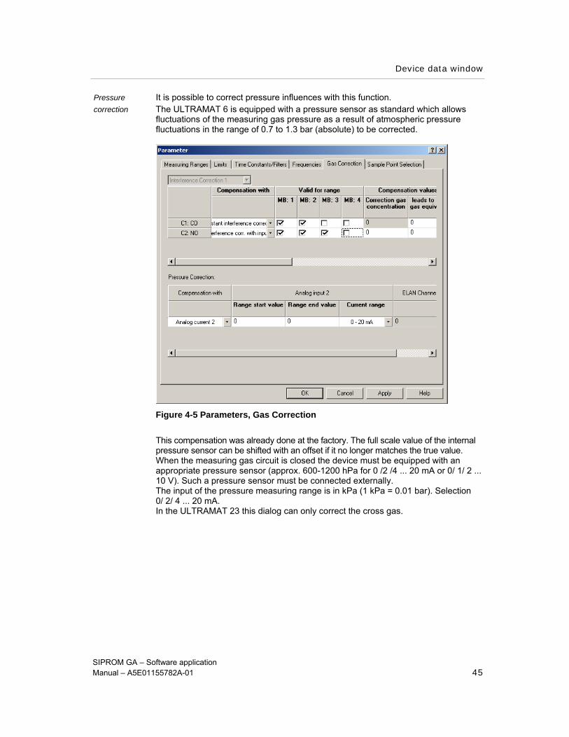
Pressure It is possible to correct pressure influences with this function. correction The ULTRAMAT 6 is equipped with a pressure sensor as standard which allows
fluctuations of the measuring gas pressure as a result of atmospheric pressure fluctuations in the range of 0.7 to 1.3 bar (absolute) to be corrected.
Figure 4-5 Parameters, Gas Correction
This compensation was already done at the factory. The full scale value of the internal pressure sensor can be shifted with an offset if it no longer matches the true value. When the measuring gas circuit is closed the device must be equipped with an appropriate pressure sensor (approx. 600-1200 hPa for 0 /2 /4 ... 20 mA or 0/ 1/ 2 ... 10 V). Such a pressure sensor must be connected externally. The input of the pressure measuring range is in kPa (1 kPa = 0.01 bar). Selection 0/ 2/ 4 ... 20 mA. In the ULTRAMAT 23 this dialog can only correct the cross gas.

Device data window
SIPROM GA – Software application Manual – A5E01155782A-01 46
Tab Measurement position switching This option is not selectable in ULTRAMAT 23.
With this function it is possible to assign a maximum of six measuring points to the device and to switch these automatically.
Prerequisite The measuring points were parameterized in the Configuration menu in the Relay Assignment tab. The corresponding relay number is visible in the table. It is also possible to assign a signal relay to every measuring point relay. This enables signaling of the respective current measuring point electrically isolated from the measurement point relay.
Every measuring point is allocated a run time (duration) for which values between 0 and 60,000 (minutes) are possible. The measuring point switching can be switched on and off.
Configuration
After selecting the Configuration sub-menu or the following button the Configuration dialog opens.
Changes in the individual tabs are transferred directly to the device by the OK button or the ACCEPT button.
Figure 4-6 Menu: Configuration
Device data window
SIPROM GA – Software application Manual – A5E01155782A-01 47
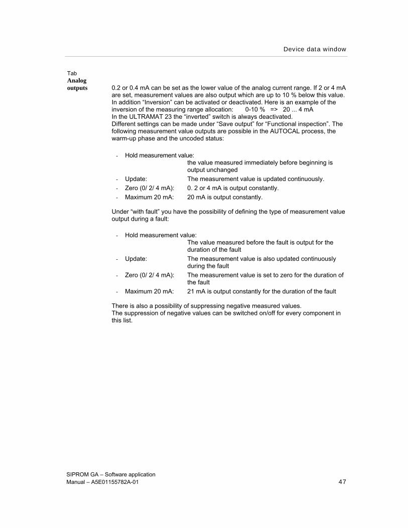
Tab Analog outputs 0.2 or 0.4 mA can be set as the lower value of the analog current range. If 2 or 4 mA
are set, measurement values are also output which are up to 10 % below this value. In addition “Inversion” can be activated or deactivated. Here is an example of the inversion of the measuring range allocation: 0-10 % => 20 ... 4 mA In the ULTRAMAT 23 the “inverted” switch is always deactivated. Different settings can be made under “Save output” for “Functional inspection”. The following measurement value outputs are possible in the AUTOCAL process, the warm-up phase and the uncoded status:
- Hold measurement value: the value measured immediately before beginning is output unchanged
- Update: The measurement value is updated continuously. - Zero (0/ 2/ 4 mA): 0. 2 or 4 mA is output constantly. - Maximum 20 mA: 20 mA is output constantly.
Under “with fault” you have the possibility of defining the type of measurement value output during a fault:
- Hold measurement value: The value measured before the fault is output for the duration of the fault
- Update: The measurement value is also updated continuously during the fault
- Zero (0/ 2/ 4 mA): The measurement value is set to zero for the duration of the fault
- Maximum 20 mA: 21 mA is output constantly for the duration of the fault There is also a possibility of suppressing negative measured values. The suppression of negative values can be switched on/off for every component in this list.

Device data window
SIPROM GA – Software application Manual – A5E01155782A-01 48
Tab Relay allocation
Relay allocation In the basic version, six (in the ULTRAMAT 23 eight) freely configurable relays are
available, the switchable output contacts (max. 33 V/ 1A) of which can be used for signaling, controlling valves or similar. If these six or eight relays are not sufficient, it is possible to retrofit another eight relays with additional electronics (optional). Every relay can be allocated a function but each function may only be allocated once. This means that for example the fault message may not be allocated to two relays.
Function selection Proceed as follows to select a function:
1. Select relay (mouseclick)
2. Select function from the list auswählen and allocate the desired function to the relay using the << key.
A function can also be transferred back to the selection list with the >> key. The following functions are available:
status messages such as fault
maintenance request
functional inspection
limit value alarms
measuring range alarms
measuring gas, zero gas, tracer gas 1(...4), measuring point 1(...6), signal measuring point (1...6),
signal contact
fluid flow measuring gas
Tab Binary inputs In the basic version, six (in the ULTRAMAT 23 poss. eight potential-free binary inputs
[0 = 0 V (0...4,5 V); 1 = 24 V (13...33 V)] are available which can be freely configured. If these six inputs are not sufficient, additional electronics with another eight binary inputs (optional) can be installed. Any one of the functions is allocated to every input but each function may only be allocated once. External system components can be monitored and visualized in this way.

Device data window
SIPROM GA – Software application Manual – A5E01155782A-01 49
.
SIPROM GA Text Function Display analyzer menu
free no effect on control
general fault fault message not indicated by a text fault 1
general maintenance request
maintenance request not indicated by a text maintenance request 1
probe heater fault text appears in main window under “System Statuses”
fault 2
measuring gas filter fault text “ ” fault 3
cooler fault text “ ” fault 4 probe heater maintenance request text “ ” maintenance request 2
measuring gas filter maintenance request text “ ” maintenance request 3
cooler maintenance request text “ ” maintenance request 4
condensation tank fault text “ ” fault 5 measuring gas pump /flow fault text “ ” fault 6
measuring gas line fault text “ ” fault 7 condensation tank maintenance request text “ ” maintenance request 5
measuring gas pump/ flow maintenance request text “ ” maintenance request 6
measuring gas line maintenance request text “ ” maintenance request 7
functional inspection (1-4) e.g. calibrations functional inspection (1-4)
trigger AUTOCAL start select component (1-2) measuring range (1-4, automatic measuring range switching)
remote measuring range switching
measuring ranges (1-4), autorange
calibrate component (1..2) sensitivity
start only for total calibration rec. cal.
calibrate adjustment zero zero cal.
trigger AUTOCAL AUTOCAL
open valve zero gas zero gas
open valve tracer gas tracer gas
open valve measuring gas measuring gas acknowledge (delete log book) acknowledge (delete log
book)
Function selection Proceed as follows to select a function:
1. Select binary input (mouse click)
Device data window
SIPROM GA – Software application Manual – A5E01155782A-01 50
2. Select function from list and allocate the desired function to the binary input with the << key.
A function can also be transferred back to the selection list with the >> key.
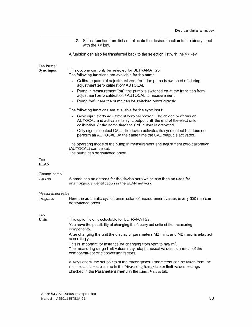
Tab Pump/ Sync input This optiona can only be selected for ULTRAMAT 23
The following functions are available for the pump: - Calibrate pump at adjustment zero “on”: the pump is switched off during
adjustment zero calibration/ AUTOCAL - Pump in measurement “on”: the pump is switched on at the transition from
adjustment zero calibration / AUTOCAL to measurement - Pump “on”: here the pump can be switched on/off directly
The following functions are available for the sync input:
- Sync input starts adjustment zero calibration. The device performs an AUTOCAL and activates its sync output until the end of the electronic calibration. At the same time the CAL output is activated.
- Only signals contact CAL: The device activates its sync output but does not perform an AUTOCAL. At the same time the CAL output is activated.
The operating mode of the pump in measurement and adjustment zero calibration (AUTOCAL) can be set. The pump can be switched on/off.
Tab ELAN
Channel name/ TAG no. A name can be entered for the device here which can then be used for
unambiguous identification in the ELAN network. Measurement value telegrams Here the automatic cyclic transmission of measurement values (every 500 ms) can
be switched on/off.
Tab Units This option is only selectable for ULTRAMAT 23.
You have the possibility of changing the factory set units of the measuring components. After changing the unit the display of parameters MB min.. and MB max. is adapted accordingly. This is important for instance for changing from vpm to mg/ m3. The measuring range limit values may adopt unusual values as a result of the component-specific conversion factors. Always check the set points of the tracer gases. Parameters can be taken from the Calibration sub-menu in the Measuring Range tab or limit values settings checked in the Parameters menu in the Limit Values tab.
Device data window
SIPROM GA – Software application Manual – A5E01155782A-01 51
Load PC data
In the Load PC data menu all parameter sets saved on the PC can be loaded back into a device. Factory settings can also be loaded with this function.
The data cannot be read on the PC!
Save PC data
With the Save PC data sub-menu the parameter sets of the device can be transferred to the PC and saved. Parameterizations made on the device are saved. In case of undesirable further parameterizations on the device, the data saved here can be called again and the original status restored.
To save, the desired path is entered and saved as a PC data file (*dat.).
Load user data With the Load User Data sub-menu, user-specific data can be loaded from the user data memory into the main memory of the device.
Note
The user data memory (EEPROM) is in the device.
Save user data (online mode)
With the Save User Data sub-menu you can save user-specific data in the user data memory. These data are then “preserved” and can be called with the Load User Data sub-menu when necessary. This is important when repairs or maintenance work are performed on a device or for example a new parameterization is to be tried out.
Note
The user data memory EEPROM is in the device. When calling the sub-menu, a prompt asks whether you really want to perform this action.
Device data window
SIPROM GA – Software application Manual – A5E01155782A-01 52
Load Factory Data (online mode)
With the Load Factory Data sub-menu the settings of the device parameters can be restored if necessary. All data in the main memory are overwritten with the values set ex-factory.
Note
The factory data memory (EEPROM) is in the device. When calling the sub-menu, a prompt asks whether you really want to perform the action.
Reset (online mode)
With the Reset sub-menu you can restart (cold start) the device, e.g. in case of a fault in the program run.
After actuating this function you have to wait for the warm-up time again. Only then is the device fully ready for operation. Also note that no communication is possible in the network for a short time.
4.2.3 The menu: Services
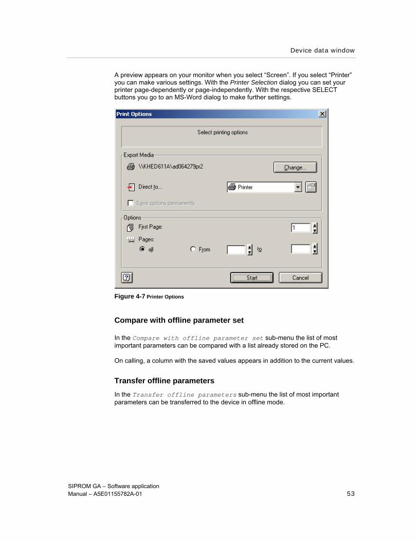
With the Print sub-menu, all the device parameters are printed. Individual settings can be made.
After selecting the sub-menu you go to the Printer Output dialog where you have to choose between “Printer” and “Screen”.
Device data window
SIPROM GA – Software application Manual – A5E01155782A-01 53
A preview appears on your monitor when you select “Screen”. If you select “Printer” you can make various settings. With the Printer Selection dialog you can set your printer page-dependently or page-independently. With the respective SELECT buttons you go to an MS-Word dialog to make further settings.
Figure 4-7 Printer Options
Compare with offline parameter set
In the Compare with offline parameter set sub-menu the list of most important parameters can be compared with a list already stored on the PC.
On calling, a column with the saved values appears in addition to the current values.
Transfer offline parameters In the Transfer offline parameters sub-menu the list of most important parameters can be transferred to the device in offline mode.
Device data window
SIPROM GA – Software application Manual – A5E01155782A-01 54
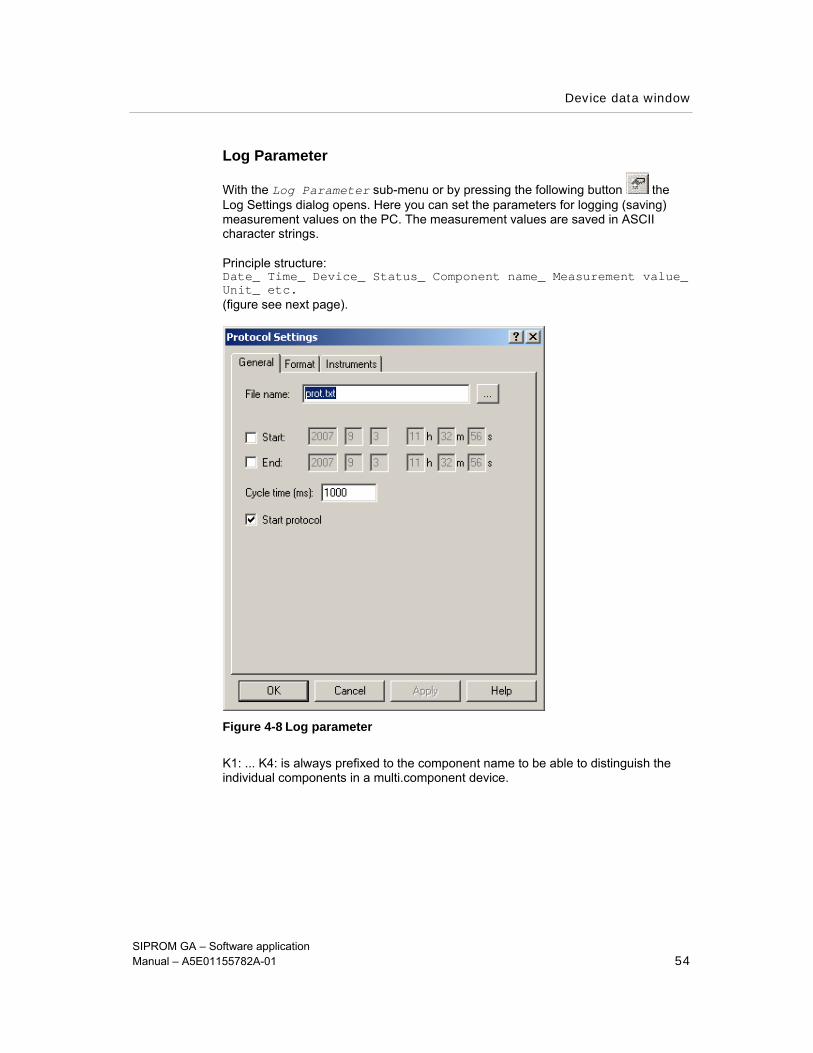
Log Parameter
With the Log Parameter sub-menu or by pressing the following button the Log Settings dialog opens. Here you can set the parameters for logging (saving) measurement values on the PC. The measurement values are saved in ASCII character strings.
Principle structure: Date_ Time_ Device_ Status_ Component name_ Measurement value_ Unit_ etc. (figure see next page).
Figure 4-8 Log parameter
K1: ... K4: is always prefixed to the component name to be able to distinguish the individual components in a multi.component device.
Device data window
SIPROM GA – Software application Manual – A5E01155782A-01 55
Tab General This tab contains general information about creating logs. The following data can be
set:
File name: A name for the log file can be assigned in the input field. You go to the file selection dialog by pressing the “ ... ” button
Beginning/ end: The measurement value logging can take place time controlled. After activating the checkbox the date and time can be specified in hours : minutes : seconds. Both values can be activated/ deactivated immediately
cycle time: Time interval in milliseconds between the individual measurement value sets to be logged
start log: The checkbox must be activated to start logging
Tab Format The format properties of the log can be defined in this tab. Not all inputs are possible
in every device:
Number of columns: Log layout is divided into columns
Ring buffer with: not integrated as standard
File splitting according to: After the specified number of lines the logging is continued in a new file. The files are numbered consecutively. This function avoids loss of files when the PC fails.
Separating character: Separating character: The separating character of the individual columns can be set here. The current country-specific setting appears in a message on the PC.
This tab lists all devices of which the measurement values can be logged. Each device can be selected individually. The following factors can also be influenced:
Decimal character: Selectable character between decimal numbers
Network: A network can be selected with the IP number. By activating / deactivating the checkbox, you can decide which devices the log settings are to be transferred to.
Tab Device

Device data window
SIPROM GA – Software application Manual – A5E01155782A-01 56
Note
The inputs are only considered for logging when you press the ACCEPT button.
Logging measurement values
With the Log Measurement Values sub-menu you can start or stop saving measurement values. All the measurement values in the network can be saved on hard disk.
The following settings are made in a dialog at the beginning of measurement value logging:
- Location and name of the log file - Selection of the devices of which the measurement values are to be logged - Determination of the sample rate: please bear iln mind that the minimum time is
calculated from the number of available devices - Maximum number of lines per file: The name of the log file is extended by a
counter. As soon as the file has reached the maximum number of lines, it is closed and a new file of the same name with an appropriate counter is created.
The data format can be read by common evaluation programs (e.g.. Text Editor/ Import to MS-Excel) The following are saved per unit of time: Date / time / device/status / component name / concentration / unit / device 2.
Device clock
Using the Device Clock sub-menu it is possible to set the date and time of the device exactly.
This is especially important to allocate faults which have been saved in the log book to a certain time. This can be very helpful for error detection.
Note
In the event of a power failure the date and time are deleted and must be reset.
Device data window
SIPROM GA – Software application Manual – A5E01155782A-01 57
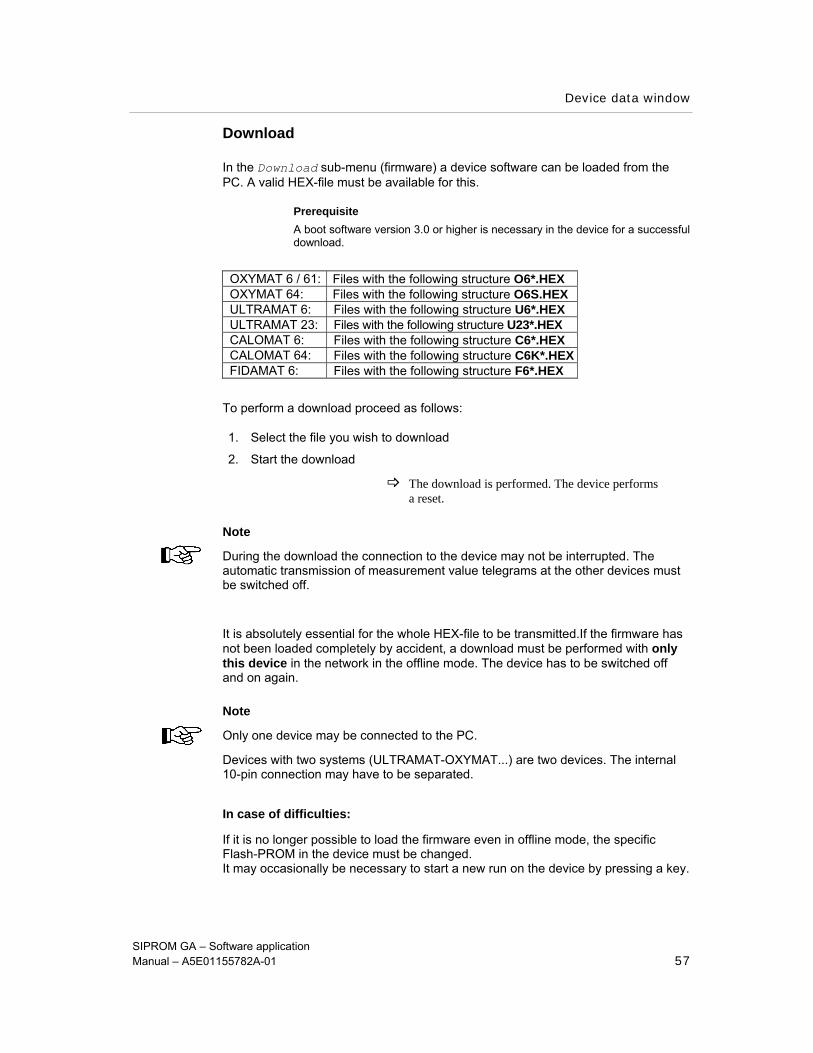
Download
In the Download sub-menu (firmware) a device software can be loaded from the PC. A valid HEX-file must be available for this.
Prerequisite A boot software version 3.0 or higher is necessary in the device for a successful download.
OXYMAT 6 / 61: Files with the following structure O6*.HEX OXYMAT 64: Files with the following structure O6S.HEX ULTRAMAT 6: Files with the following structure U6*.HEX ULTRAMAT 23: Files with the following structure U23*.HEX CALOMAT 6: Files with the following structure C6*.HEX CALOMAT 64: Files with the following structure C6K*.HEX FIDAMAT 6: Files with the following structure F6*.HEX
To perform a download proceed as follows:
1. Select the file you wish to download
2. Start the download
The download is performed. The device performs a reset.
Note
During the download the connection to the device may not be interrupted. The automatic transmission of measurement value telegrams at the other devices must be switched off.
It is absolutely essential for the whole HEX-file to be transmitted.If the firmware has not been loaded completely by accident, a download must be performed with only this device in the network in the offline mode. The device has to be switched off and on again.
Note
Only one device may be connected to the PC.
Devices with two systems (ULTRAMAT-OXYMAT...) are two devices. The internal 10-pin connection may have to be separated.
In case of difficulties:
If it is no longer possible to load the firmware even in offline mode, the specific Flash-PROM in the device must be changed. It may occasionally be necessary to start a new run on the device by pressing a key.
Device data window
SIPROM GA – Software application Manual – A5E01155782A-01 58
Download Profibus
In the Download Profibus sub-menu software of the Profibus module can be loaded from the PC. A valid HEX-file must be available for this.
Prerequisite A boot software version 0.2.0 or higher is necessary in the module for a successful download.
Profibus module DP, PA or PA Ex Files with the following structure CGA_*.HEX
To perform a download proceed as follows:
1. Select the file you wish to download
2. Start the download
The download is performed. The device performs a reset.
Note
During the download the connection to the device may not be interrupted. The automatic transmission of measurement value telegrams at the other devices must be switched off.
It is absolutely essential for the whole HEX-file to be transmitted.If the firmware has not been loaded completely by accident, the module reloads the former firmware after reset. Restart of the module will take a longer time after finished or interrupted download.
4.2.4 The menu: Back
Back to main window
After selecting the Back to main window sub-menu or the following button the main window of the application opens. Any change in the operating mode from online to offline is taken into account.
4.2.5 The menu: Help
In the Help menu the three sub-menus Operating help, Index and Program info correspond to the items listed in the main window.
Appendix
SIPROM GA – Software application Manual – A5E01155782A-01 59
5 Appendix
5.1 Operation with modem / ISDN / network
It is possible to operate the program via modem etc. The use of LAPLINK or similar remote control programs is also allowed. In this way PC <-> PC links can be implemented with ELAN.
5.2 Language versions
The program is available in German and English. The used language is predefined during program installation. It is not possible to switch languages during operation. The WINDOWS standard dialogs used for selecting data, setting the printer etc. appear in the language under which the Windows system was installed.
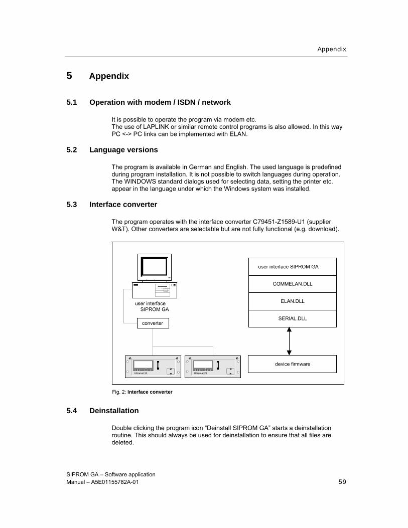
5.3 Interface converter
The program operates with the interface converter C79451-Z1589-U1 (supplier W&T). Other converters are selectable but are not fully functional (e.g. download).
5.4 Deinstallation
Double clicking the program icon “Deinstall SIPROM GA” starts a deinstallation routine. This should always be used for deinstallation to ensure that all files are deleted.
user interfaceSIPROM GA
Ultramat 23 Ultramat 23
converter
user interface SIPROM GA
COMMELAN.DLL
ELAN.DLL
SERIAL.DLL
device firmware
Fig. 2: Interface converter
Appendix
SIPROM GA – Software application Manual – A5E01155782A-01 60
5.5 Addresses
In case of problems with SIPROM GA or questions about the equipment, please contact the following address: SIEMENS CSC 1, chemin de la Sandlach F-67506 Haguenau Telephone: + 33 3 88 90 6677 FAX: + 33 3 88 90 6688


![Apps Framework API[V1.10]](https://img.pdfslide.net/doc/110x75/55400cb64a7959251a8b49d2/apps-framework-apiv110.jpg)


![Apps Framework Scene Manager API[V1.10]](https://img.pdfslide.net/doc/110x75/543d1210afaf9fbe618b4985/apps-framework-scene-manager-apiv110.jpg)