Embed Size (px)
Citation preview

SIPROTEC 5 V8.01 and higherFault Recorder 7KE85
Technical Data
Extract from manual C53000-G5040-C018-7, chapter 11
Smart Infrastructure

ii NOTEFor your own safety, observe the warnings and safety instructions contained in this document, if available.
Disclaimer of LiabilitySubject to changes and errors. The information given inthis document only contains general descriptions and/orperformance features which may not always specificallyreflect those described, or which may undergo modifica-tion in the course of further development of the products.The requested performance features are binding only whenthey are expressly agreed upon in the concluded contract.Document version: C53000-G5040-C018-7.01Edition: 12.2019Version of the product described: V8.01 and higher
CopyrightCopyright © Siemens 2019. All rights reserved.The disclosure, duplication, distribution and editing of thisdocument, or utilization and communication of the contentare not permitted, unless authorized in writing. All rights,including rights created by patent grant or registration of autility model or a design, are reserved.
TrademarksSIPROTEC™, DIGSI™, SIGRA™, SIGUARD™, SAFIR™, SICAM™,and MindSphere™ are trademarks of Siemens. Any unau-thorized use is prohibited. All other designations in thisdocument may represent trademarks whose use by thirdparties for their own purposes may violate the proprietaryrights of the owner.

Preface
Purpose of the ManualThis manual describes the functions of the fault recorder 7KE85.
Target AudienceSystem configurers, commissioning engineers, and persons entrusted with the setting, testing and mainte-nance of fault recorder equipment, and operational crew in electrical installations and power plants.
ScopeThis manual applies to the SIPROTEC 5 device family.
Further Documentation
[dwprefdm-221012-01.tif, 3, en_US]
• Device manualsEach Device manual describes the functions and applications of a specific SIPROTEC 5 device. The printedmanual and the online help for the device have the same informational structure.
• Hardware manualThe Hardware manual describes the hardware building blocks and device combinations of the SIPROTEC 5device family.
• Operating manualThe Operating manual describes the basic principles and procedures for operating and assembling thedevices of the SIPROTEC 5 range.
SIPROTEC 5, Fault Recorder, Manual 3C53000-G5040-C018-7, Edition 12.2019

• Communication protocol manualThe Communication protocol manual contains a description of the protocols for communication withinthe SIPROTEC 5 device family and to higher-level network control centers.
• Product informationThe Product information includes general information about device installation, technical data, limitingvalues for input and output modules, and conditions when preparing for operation. This document isprovided with each SIPROTEC 5 device.
• Engineering GuideThe Engineering Guide describes the essential steps when engineering with DIGSI 5. In addition, the Engi-neering Guide shows you how to load a planned configuration to a SIPROTEC 5 device and update thefunctionality of the SIPROTEC 5 device.
• DIGSI 5 online helpThe DIGSI 5 online help contains a help package for DIGSI 5 and CFC.The help package for DIGSI 5 includes a description of the basic operation of software, the DIGSI princi-ples and editors. The help package for CFC includes an introduction to CFC programming, basic examplesof working with CFC, and a reference chapter with all the CFC blocks available for the SIPROTEC 5 range.
• SIPROTEC 5/DIGSI 5 TutorialThe tutorial on the DVD contains brief information about important product features, more detailed infor-mation about the individual technical areas, as well as operating sequences with tasks based on practicaloperation and a brief explanation.
• SIPROTEC 5 catalogThe SIPROTEC 5 catalog describes the system features and the devices of SIPROTEC 5.
• Selection guide for SIPROTEC and ReyrolleThe selection guide offers an overview of the device series of the Siemens protection devices, and adevice selection table.
Indication of Conformity
This product complies with the directive of the Council of the European Communitieson harmonization of the laws of the Member States concerning electromagneticcompatibility (EMC Directive 2014/30/EU), restriction on usage of hazardoussubstances in electrical and electronic equipment (RoHS Directive 2011/65/EU), andelectrical equipment for use within specified voltage limits (Low Voltage Directive2014/35/EU).This conformity has been proved by tests performed according to the Council Directivein accordance with the product standard EN 60255-26 (for EMC directive), the standardEN 50581 (for RoHS directive), and with the product standard EN 60255-27 (for LowVoltage Directive) by Siemens.The device is designed and manufactured for application in an industrial environment.The product conforms with the international standards of IEC 60255 and the Germanstandard VDE 0435.
StandardsIEEE Std C 37.90The technical data of the product is approved in accordance with UL.For more information about the UL database, see ul.comYou can find the product with the UL File Number E194016.
IND. CONT. EQ.69CA
Preface
4 SIPROTEC 5, Fault Recorder, ManualC53000-G5040-C018-7, Edition 12.2019
Additional SupportFor questions about the system, contact your Siemens sales partner.
Customer Support CenterOur Customer Support Center provides a 24-hour service.Siemens AGCustomer Support CenterHumboldtstrasse 5990459 NurembergGermanyE-mail: [email protected]
Training CoursesInquiries regarding individual training courses should be addressed to our Training Center:Siemens AG Phone: +49 (911) 433-7415Siemens Power Academy TD Fax: +49 (911) 433-7929Humboldtstrasse 59 E-mail: [email protected] Nuremberg Internet: www.siemens.com/poweracademyGermany
Notes on SafetyThis document is not a complete index of all safety measures required for operation of the equipment (moduleor device). However, it comprises important information that must be followed for personal safety, as well asto avoid material damage. Information is highlighted and illustrated as follows according to the degree ofdanger:
! DANGERDANGER means that death or severe injury will result if the measures specified are not taken.
² Comply with all instructions, in order to avoid death or severe injuries.
! WARNINGWARNING means that death or severe injury may result if the measures specified are not taken.
² Comply with all instructions, in order to avoid death or severe injuries.
! CAUTIONCAUTION means that medium-severe or slight injuries can occur if the specified measures are not taken.
² Comply with all instructions, in order to avoid moderate or minor injuries.
Preface
SIPROTEC 5, Fault Recorder, Manual 5C53000-G5040-C018-7, Edition 12.2019

NOTICENOTICE means that property damage can result if the measures specified are not taken.
² Comply with all instructions, in order to avoid property damage.
ii NOTEImportant information about the product, product handling or a certain section of the documentationwhich must be given attention.
Qualified Electrical Engineering PersonnelOnly qualified electrical engineering personnel may commission and operate the equipment (module, device)described in this document. Qualified electrical engineering personnel in the sense of this manual are peoplewho can demonstrate technical qualifications as electrical technicians. These persons may commission,isolate, ground and label devices, systems and circuits according to the standards of safety engineering.
Proper UseThe equipment (device, module) may be used only for such applications as set out in the catalogs and thetechnical description, and only in combination with third-party equipment recommended and approved bySiemens.Problem-free and safe operation of the product depends on the following:
• Proper transport
• Proper storage, setup and installation
• Proper operation and maintenanceWhen electrical equipment is operated, hazardous voltages are inevitably present in certain parts. If properaction is not taken, death, severe injury or property damage can result:
• The equipment must be grounded at the grounding terminal before any connections are made.
• All circuit components connected to the power supply may be subject to dangerous voltage.
• Hazardous voltages may be present in equipment even after the supply voltage has been disconnected(capacitors can still be charged).
• Operation of equipment with exposed current-transformer circuits is prohibited. Before disconnecting theequipment, ensure that the current-transformer circuits are short-circuited.
• The limiting values stated in the document must not be exceeded. This must also be considered duringtesting and commissioning.
Used Symbols on Device
No. Symbol Description
1 Direct current, IEC 60417, 5031
2 Alternating current, IEC 60417, 5032
3 Direct and alternating current, IEC 60417, 5033
4 Earth (ground) terminal, IEC 60417, 5017
5 Protective conductor terminal, IEC 60417, 5019
Preface
6 SIPROTEC 5, Fault Recorder, ManualC53000-G5040-C018-7, Edition 12.2019

No. Symbol Description
6 Caution, risk of electric shock
7 Caution, risk of danger, ISO 7000, 0434
8 Protective Insulation, IEC 60417, 5172, Safety Class II devices
9 Guideline 2002/96/EC for electrical and electronic devices
10 Guideline for the Eurasian Market
Preface
SIPROTEC 5, Fault Recorder, Manual 7C53000-G5040-C018-7, Edition 12.2019

Technical Data
11.1 General Device Data 46211.2 Date and Time Synchronization 47111.3 Phasor Measurement Unit 47211.4 Recorder Functions 47311.5 Supervision Functions 47611.6 Operational Measured Values and Statistical Values 47911.7 CFC 483
11
SIPROTEC 5, Fault Recorder, Manual 461C53000-G5040-C018-7, Edition 12.2019

General Device Data
Supply Voltage
Integrated Power SupplyFor modular devices, the following modules contain a power supply:PS201 – Power supply of the base module and of the 1st device rowPS203 – Power supply of the 2nd device rowPS204 – Redundant power supplyCB202 – Plug-in module assembly with integrated power supply, for example, to accommodate communica-tion modulesPermissible voltageranges(PS201, PS203, PS204,CB202)
DC 19 V to DC 60 V DC 48 V to DC 300 VAC 80 V to AC 265 V, 50 Hz/60 Hz
Auxiliary rated voltage VH
(PS201, PS203, PS204,CB202)
DC 24 V/DC 48 V DC 60 V/DC 110 V/DC 125 V/DC 220 V/DC 250 V orAC 100 V/AC 115 V/AC 230 V, 50 Hz/60 Hz
Permissible voltageranges (PS101)Only for non-modulardevices
DC 19 V to DC 60 V DC 48 V to 150 V DC 88 V to DC 300 VAC 80 V to AC 265 V,50 Hz/60 Hz
Auxiliary rated voltage VH(PS101)Only for non-modulardevices
DC 24 V/DC 48 V DC 60 V/DC 110 V/DC 125 V
DC 110 V/ DC 125 V/DC 220 V/DC 250 VorAC 100 V/AC 115 V/AC 230 V, 50 Hz/60 Hz
Superimposed alternatingvoltage, peak-to-peak,IEC 60255-11,IEC 61000-4-17
≤ 15 % of the DC auxiliary rated voltage (applies only to direct voltage)
Inrush current ≤ 18 ARecommended externalprotection
Miniature circuit breaker 6 A, characteristic C according to IEC 60898
Internal fuse– DC 24 V to DC 48 V DC 60 V to DC 125 V DC 24 V to DC 48 V
AC 100 V to AC 230 VPS101Only for non-modulardevices
4 A inert, AC 250 V,DC 150 V,UL recognizedSIBA type 179200 orSchurter type SPT 5x20
2 A time-lag, AC 250 V, DC 300 V, UL recognizedSIBA type 179200 or Schurter type SPT 5x20
PS201, PS203, CB202(to device version xA)
4 A inert, AC 250 V,DC 150 V,UL recognizedSIBA type 179200 orSchurter type SPT 5x20
2 A time-lag, AC 250 V, DC 300 V, UL recognizedSIBA type 179200 or Schurter type SPT 5x20
11.1
11.1.1
Technical Data11.1 General Device Data
462 SIPROTEC 5, Fault Recorder, ManualC53000-G5040-C018-7, Edition 12.2019

Integrated Power SupplyPS201, PS203, PS204,CB202(Device version xB andhigher)
4 A inert, AC 250 V,DC 150 V,UL recognizedSIBA type 179200 orSchurter type SPT 5x20
3.15 A time-lag, AC 250 V, DC 300 V, UL recognizedSIBA type 179200 or Schurter type SPT 5x20
Power consumption (life relay active)– DC AC 230 V/50 Hz AC 115 V/50 Hz1/3 module, non-modularWithout plug-in modules
7 W 16 VA 12.5 VA
1/3 base module, modularWithout plug-in modules
13 W 55 VA 40 VA
1/6 expansion module 3 W 6 VA 6 VA1/6 plug-in moduleassembly without plug-inmodules (modules CB202)
3.5 W 14 VA 7 VA
Plug-in module for basemodule or plug-in moduleassembly (for example,communication module)
< 5 W < 6 VA < 6 VA
Stored-energy time for auxiliary voltage outage orshort circuit, modular devicesIEC 61000-4-11IEC 61000-4-29
For V ≥ DC 24 V ≥ 50 msFor V ≥ DC 110 V ≥ 50 msFor V ≥ AC 115 V ≥ 50 ms
Stored-energy time for auxiliary voltage outage orshort circuit, non-modular devicesIEC 61000-4-11IEC 61000-4-29
For V ≥ DC 24 V ≥ 20 msFor V ≥ DC 60 V ≥ 50 msFor V ≥ AC 115 V ≥ 200 ms
Binary Inputs
Standard Binary Input
Rated voltage range DC 24 V to 250 VThe binary inputs of SIPROTEC 5 are bipolar, with the exception of thebinary inputs on the modules IO230, IO231, and IO233.
Current consumption, excited Approx. DC 0.6 mA to 2.5 mA (independent of the control voltage)Power consumption, max. 0.6 WPickup time Approx. 3 msDropout time21 Capacitive load (supply-line capaci-
tance)Dropout time
< 5 nF < 4 ms< 10 nF < 6 ms< 50 nF < 10 ms< 220 nF < 35 ms
11.1.2
21 For time-critical applications with low-active signals, consider the specified dropout times. If necessary, provide for active dischargeof the binary input (for example, a resistor in parallel to the binary input or using a change-over contact).
Technical Data11.1 General Device Data
SIPROTEC 5, Fault Recorder, Manual 463C53000-G5040-C018-7, Edition 12.2019
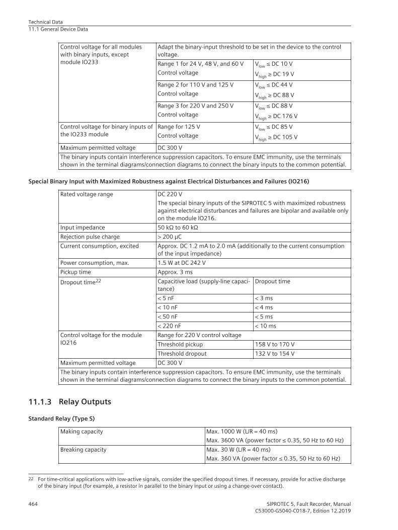
Control voltage for all moduleswith binary inputs, exceptmodule IO233
Adapt the binary-input threshold to be set in the device to the controlvoltage.Range 1 for 24 V, 48 V, and 60 VControl voltage
Vlow ≤ DC 10 VVhigh ≥ DC 19 V
Range 2 for 110 V and 125 VControl voltage
Vlow ≤ DC 44 VVhigh ≥ DC 88 V
Range 3 for 220 V and 250 VControl voltage
Vlow ≤ DC 88 VVhigh ≥ DC 176 V
Control voltage for binary inputs ofthe IO233 module
Range for 125 VControl voltage
Vlow ≤ DC 85 VVhigh ≥ DC 105 V
Maximum permitted voltage DC 300 VThe binary inputs contain interference suppression capacitors. To ensure EMC immunity, use the terminalsshown in the terminal diagrams/connection diagrams to connect the binary inputs to the common potential.
Special Binary Input with Maximized Robustness against Electrical Disturbances and Failures (IO216)
Rated voltage range DC 220 VThe special binary inputs of the SIPROTEC 5 with maximized robustnessagainst electrical disturbances and failures are bipolar and available onlyon the module IO216.
Input impedance 50 kΩ to 60 kΩRejection pulse charge > 200 µCCurrent consumption, excited Approx. DC 1.2 mA to 2.0 mA (additionally to the current consumption
of the input impedance)Power consumption, max. 1.5 W at DC 242 VPickup time Approx. 3 msDropout time22 Capacitive load (supply-line capaci-
tance)Dropout time
< 5 nF < 3 ms< 10 nF < 4 ms< 50 nF < 5 ms< 220 nF < 10 ms
Control voltage for the moduleIO216
Range for 220 V control voltageThreshold pickup 158 V to 170 VThreshold dropout 132 V to 154 V
Maximum permitted voltage DC 300 VThe binary inputs contain interference suppression capacitors. To ensure EMC immunity, use the terminalsshown in the terminal diagrams/connection diagrams to connect the binary inputs to the common potential.
Relay Outputs
Standard Relay (Type S)
Making capacity Max. 1000 W (L/R = 40 ms)Max. 3600 VA (power factor ≤ 0.35, 50 Hz to 60 Hz)
Breaking capacity Max. 30 W (L/R = 40 ms)Max. 360 VA (power factor ≤ 0.35, 50 Hz to 60 Hz)
11.1.3
22 For time-critical applications with low-active signals, consider the specified dropout times. If necessary, provide for active dischargeof the binary input (for example, a resistor in parallel to the binary input or using a change-over contact).
Technical Data11.1 General Device Data
464 SIPROTEC 5, Fault Recorder, ManualC53000-G5040-C018-7, Edition 12.2019

AC and DC contact voltage 250 VPermissible current per contact (continuous) 5 APermissible current per contact (switching on andholding)
30 A for 1 s (make contact)
Short-time current across closed contact 250 A for 30 msTotal permissible current for contacts connected tocommon potential
5 A
Switching time OOT (Output Operating Time)Additional delay of the output medium used
Make time: typical: 8 ms; maximum: 10 msBreak time: typical: 2 ms; maximum: 5 ms
Max. rated data of the output contacts in accordancewith UL certification
DC 24 V, 5 A, General PurposeDC 48 V, 0.8 A, General PurposeDC 240 V, 0.1 A, General PurposeAC 240 V, 5 A, General PurposeAC 120 V, 1/6 hpAC 250 V, 1/2 hpB300R300
Interference suppression capacitors across thecontacts
4.7 nF, ± 20 %, AC 250 V
Fast Relay (Type F)
Making capacity Max. 1000 W (L/R = 40 ms)Max. 3600 VA (power factor ≤ 0.35, 50 Hz to 60 Hz)
Breaking capacity Max. 30 W (L/R = 40 ms)Max. 360 VA (power factor ≤ 0.35, 50 Hz to 60 Hz)
AC and DC contact voltage 250 VPermissible current per contact (continuous) 5 APermissible current per contact (switching on andholding)
30 A for 1 s (make contact)
Short-time current across closed contact 250 A for 30 msTotal permissible current for contacts connected tocommon potential
5 A
Switching time OOT (Output Operating Time)Additional delay of the output medium used
Make time: typical: 4 ms; maximum: 5 msBreak time: typical: 2 ms; maximum: 5 ms
Rated data of the output contacts in accordance withUL certification
DC 24 V, 5 A, General PurposeDC 48 V, 0.8 A, General PurposeDC 240 V, 0.1 A, General PurposeAC 120 V, 5 A, General PurposeAC 250 V, 5 A, General PurposeAC 250 V, 0.5 hpB300R300
Interference suppression capacitors across thecontacts
4.7 nF, ± 20 %, AC 250 V
Supervision 2-channel activation with cyclic testing (only for makecontact)
Technical Data11.1 General Device Data
SIPROTEC 5, Fault Recorder, Manual 465C53000-G5040-C018-7, Edition 12.2019
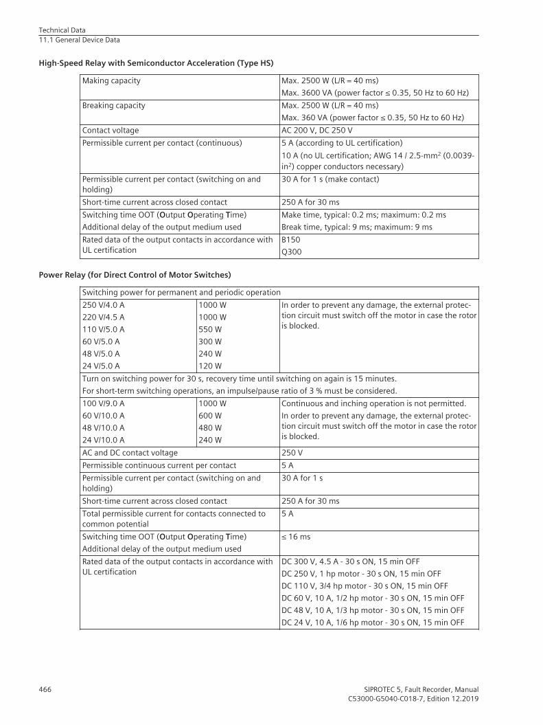
High-Speed Relay with Semiconductor Acceleration (Type HS)
Making capacity Max. 2500 W (L/R = 40 ms)Max. 3600 VA (power factor ≤ 0.35, 50 Hz to 60 Hz)
Breaking capacity Max. 2500 W (L/R = 40 ms)Max. 360 VA (power factor ≤ 0.35, 50 Hz to 60 Hz)
Contact voltage AC 200 V, DC 250 VPermissible current per contact (continuous) 5 A (according to UL certification)
10 A (no UL certification; AWG 14 / 2.5-mm2 (0.0039-in2) copper conductors necessary)
Permissible current per contact (switching on andholding)
30 A for 1 s (make contact)
Short-time current across closed contact 250 A for 30 msSwitching time OOT (Output Operating Time)Additional delay of the output medium used
Make time, typical: 0.2 ms; maximum: 0.2 msBreak time, typical: 9 ms; maximum: 9 ms
Rated data of the output contacts in accordance withUL certification
B150Q300
Power Relay (for Direct Control of Motor Switches)
Switching power for permanent and periodic operation250 V/4.0 A220 V/4.5 A110 V/5.0 A60 V/5.0 A48 V/5.0 A24 V/5.0 A
1000 W1000 W550 W300 W240 W120 W
In order to prevent any damage, the external protec-tion circuit must switch off the motor in case the rotoris blocked.
Turn on switching power for 30 s, recovery time until switching on again is 15 minutes.For short-term switching operations, an impulse/pause ratio of 3 % must be considered.100 V/9.0 A60 V/10.0 A48 V/10.0 A24 V/10.0 A
1000 W600 W480 W240 W
Continuous and inching operation is not permitted.In order to prevent any damage, the external protec-tion circuit must switch off the motor in case the rotoris blocked.
AC and DC contact voltage 250 VPermissible continuous current per contact 5 APermissible current per contact (switching on andholding)
30 A for 1 s
Short-time current across closed contact 250 A for 30 msTotal permissible current for contacts connected tocommon potential
5 A
Switching time OOT (Output Operating Time)Additional delay of the output medium used
≤ 16 ms
Rated data of the output contacts in accordance withUL certification
DC 300 V, 4.5 A - 30 s ON, 15 min OFFDC 250 V, 1 hp motor - 30 s ON, 15 min OFFDC 110 V, 3/4 hp motor - 30 s ON, 15 min OFFDC 60 V, 10 A, 1/2 hp motor - 30 s ON, 15 min OFFDC 48 V, 10 A, 1/3 hp motor - 30 s ON, 15 min OFFDC 24 V, 10 A, 1/6 hp motor - 30 s ON, 15 min OFF
Technical Data11.1 General Device Data
466 SIPROTEC 5, Fault Recorder, ManualC53000-G5040-C018-7, Edition 12.2019

Interference suppression capacitors across thecontacts
4.7 nF, ± 20 %, AC 250 V
The power relays operate in interlocked mode, that is, only one relay of each switching pair picks up at a timethereby avoiding a power-supply short circuit.
Design Data
Masses
Device SizeWeight of the Modular Devices
Type of construction 1/3 1/2 2/3 5/6 1/1Flush-mounting device 4.4 kg 7.2 kg 9.9 kg 12.7 kg 15.5 kgSurface-mounted device with inte-grated on-site operation panel
7.4 kg 11.7 kg 15.9 kg 20.2 kg 24.5 kg
Surface-mounted device withdetached on-site operation panel
4.7 kg 7.8 kg 10.8 kg 13.9 kg 17.0 kg
Size WeightDetached on-site operation panel 1/3 1.9 kgDetached on-site operation panel 1/6 1.1 kg
Device SizeWeight of the Non-Modular Devices 7xx81, 7xx82
Type of construction 1/3Flush-mounting device 3.6 kgBracket for non-modular surface-mounted variant
1.9 kg
Dimensions of the Base and 1/3 Modules
Type of Construction (Maximum Dimensions) Width over all x Height over all x Depth (incl.Current Terminal), Width and Depth Each Roundedup to the Next Full mm (in Inches)
Flush-mounting device 150 mm x 266 mm x 229 mm(5.91 x 10.47 x 9.02)
Surface-mounted device with integrated on-site oper-ation panel
150 mm x 314 mm x 337 mm(5.91 x 12.36 x 13.27)
Surface-mounted device with detached on-site opera-tion panel
150 mm x 314 mm x 230 mm(5.91 x 12.36 x 9.06)
11.1.4
Technical Data11.1 General Device Data
SIPROTEC 5, Fault Recorder, Manual 467C53000-G5040-C018-7, Edition 12.2019

Dimensions of the Device Rows
Type ofConstruction(MaximumDimensions)
Width over all x Height over all x Depth (incl. Current Terminal), Width and DepthEach Rounded up to the Next Full mm (in Inches)
Type of construc-tion
1/3 1/2 2/3 5/6 1/1
Flush-mountingdevice
150 mm x266 mm x229 mm(5.91 x 10.47 x9.02)
225 mm x266 mm x229 mm(8.86 x 10.47 x9.02)
300 mm x266 mm x229 mm(11.81 x 10.47 x9.02)
375 mm x266 mm x229 mm(14.76 x 10.47 x9.02)
450 mm x266 mm x229 mm(17.72 x 10.47 x9.02)
Surface-mounted devicewith integratedon-site operationpanel
150 mm x314 mm x337 mm(5.91 x 12.36 x13.27)
225 mm x314 mm x337 mm(8.86 x 12.36 x13.27)
300 mm x314 mm x337 mm(11.81 x 12.36 x13.27)
375 mm x314 mm x337 mm(14.76 x 12.36 x13.27)
450 mm x314 mm x337 mm(17.72 x 12.36 x13.27)
Surface-mounted devicewith detachedon-site operationpanel
150 mm x314 mm x230 mm(5.91 x 12.36 x9.06)
225 mm x314 mm x230 mm(8.86 x 12.36 x9.06)
300 mm x314 mm x230 mm(11.81 x 12.36 x9.06)
375 mm x314 mm x230 mm(14.76 x 12.36 x9.06)
450 mm x314 mm x230 mm(17.72 x 12.36 x9.06)
Expansion Module Dimensions
Type of Construction (Maximum Dimensions) Width x Height x Depth, Width and Depth EachRounded up to the Next Full mm (in Inches)
Flush-mounting device 75 mm x 266 mm x 229 mm(2.95 x 10.47 x 9.02)
Surface-mounted device with integrated on-site oper-ation panel
75 mm x 314 mm x 337 mm(2.95 x 12.36 x 13.27)
Surface-mounted device with detached on-site opera-tion panel
75 mm x 314 mm x 230 mm(2.95 x 12.36 x 9.06)
Plug-In Module Dimensions
Type of Construction (Maximum Dimensions) Width x Height x Depth (in Inches)USART-Ax-xEL, ETH-Bx-xEL 61 mm x 45 mm x 120.5 mm
(2.4 x 1.77 x 4.74)USART-Ax-xFO, ETH-Bx-xFO (without protectioncover)
61 mm x 45 mm x 132.5 mm(2.4 x 1.77 x 5.22)
ANAI-CA-4EL 61 mm x 45 mm x 119.5 mm(2.4 x 1.77 x 4.7)
ARC-CD-3FO 61 mm x 45 mm x 120.5 mm(2.4 x 1.77 x 4.74)
Minimum Bending Radii of the Connecting Cables Between the On-Site Operation Panel and the Base Module
Fiber-optic cable R = 50 mmPay attention to the length of the cable protectionsleeve, which you must also include in calculations.
D-Sub cable R = 50 mm (minimum bending radius)
Technical Data11.1 General Device Data
468 SIPROTEC 5, Fault Recorder, ManualC53000-G5040-C018-7, Edition 12.2019

Degree of Protection According to IEC 60529
For equipment in the surface-mounted housing IP5423 for frontFor equipment in the flush-mounting housing IP5423 for frontFor operator protection (back side) IP2x for current terminal (installed)
IP2x for voltage terminal (installed)Degree of pollution, IEC 60255-27 2Maximum operating altitude above sea level 2000 m (6561.68 ft)
UL Note
Type 1 if mounted into a door or front cover of an enclosure.When expanding the device with the 2nd device row, then they must be mounted completely inside anenclosure.
Tightening Torques for Terminal Screws
Type of Line Current Terminal Voltage Terminal withSpring-Loaded Terminals
Voltage Terminal withScrew Connection
Stranded wires with ring-type lug
2.7 Nm No ring-type lug No ring-type lug
Stranded wires with boot-lace ferrules or pin-typelugs
2.7 Nm 1.0 Nm 0.6 Nm
Solid conductor, bare(2 mm2)
2.0 Nm 1.0 Nm –
Bare stranded wire Not permitted 1 Nm 0.6 Nm
ii NOTEFor current and voltage terminals, the maximum speed of the tool must not exceed 640 rpm.
ii NOTEUse copper cables only.
Torques for Other Screw Types
Screw Type TorqueM4 x 20 1.2 NmM4 x 8 1.2 NmM2.5 x 6 0.39 NmCountersunk screw, M2.5 x 6 0.39 NmCountersunk screw, M2.5 x 8 0.39 NmCollar screw, M4 x 20 0.7 Nm
Influencing Variables for Measured Values
Auxiliary voltage 0.8 Var to 1.2 Var ≤ 0.2 %Ambient temperature -10 °C to 55 °C ≤ 0.5 %/10 K
11.1.5
23 The provided plug-in label must be used for expansion modules with LEDs.
Technical Data11.1 General Device Data
SIPROTEC 5, Fault Recorder, Manual 469C53000-G5040-C018-7, Edition 12.2019

Frequency: 45 Hz to 65 Hz ≤ 1 %Harmonics
• Up to 10 % of 3rd harmonics• Up to 10 % of 5th harmonics
≤ 1 %≤ 1 %
Warmup ≤ 0.3 %Transient excess pickup in fundamental component measurementmethod for τ > 100 ms (with complete unbalance)
≤ 5 %
EMC interference24 ≤ 1.5 %
SDHC Memory Card
ii NOTEYou can use only Siemens SDHC memory cards.
Capacity 16 GB25
Performance class ≥ Class 10Temperature range -40 °C to +85 °CFlash type SLC
Dimensions
Width x Height x Depth (in Inches)SDHC memory card 24 mm x 32 mm x 2.1 mm (0.94 x 1.26 x 0.08)
11.1.6
24 Exception: Magnetic field at operating frequency and 1000 A/m ≤ 5 %25 Usable capacity: Approx. 15 GB
Technical Data11.1 General Device Data
470 SIPROTEC 5, Fault Recorder, ManualC53000-G5040-C018-7, Edition 12.2019

Date and Time SynchronizationDate format DD.MM.YYYY (Europe)
MM/DD/YYYY (USA)YYYY-MM-DD (China)
Time source 1, time source 2 NoneIRIG BDCF77PISNTP
Time zone 1, time zone 2 LocalUTC
Failure indication after 0 s to 3600 sTime zone and daylight saving time Transfer of PC settings
Manually setting the time zonesTime zone offset with respect to GMT -720 min to 840 minSwitching over to daylight saving time Active
InactiveBeginning of daylight saving time Input: Day and timeEnd of daylight saving time Input: Day and timeOffset daylight saving time -120 to 120 [steps of 15]
11.2
Technical Data11.2 Date and Time Synchronization
SIPROTEC 5, Fault Recorder, Manual 471C53000-G5040-C018-7, Edition 12.2019

Phasor Measurement UnitAccuracy
IEEE Standard for SynchrophasorMeasurementsIEEE Std C37.118.1aTM-2014
Data TransferIEEE Standard for SynchrophasorData transferIEEE Std C37.118.2TM-2011
11.3
Technical Data11.3 Phasor Measurement Unit
472 SIPROTEC 5, Fault Recorder, ManualC53000-G5040-C018-7, Edition 12.2019

Recorder Functions
Fast-Scan Recorder
Setting Values
Fast-Scan Recorder Setting Range IncrementMemory capacity 0.200 GB to 15.000 GB Increments of 1Maximum record time 1.0 s to 90.0 s Increments of 0.1Pre-trigger time 0 s to 3.0 s Increments of 0.1Post-trigger time 1.0 s to 90.0 s Increments of 0.1Manual record time 1.0 s to 90.0 s Increments of 0.1Sampling frequency 1 kHz to 16 kHz Increments of 1, 2, 4, 8, 16Retrigger blocking time 0.0 s to 3600 s Increments of 0.1
Number of Recorder Instances
Fast-scan recorder 1 (fix)
Signals to be RecordedRefer to Number of Routable Measured Values (MV) and Binary Tracks (SPS), Page 474
Trigger
Frequency triggerPower triggerVoltage triggerCurrent trigger
Slow-Scan Recorder
Setting Values
Slow-Scan Recorder Setting Range IncrementMemory capacity 0.200 GB to 14.800 GB Increments of 1Maximum record time 1 min to 90 min Increments of 1Pre-trigger time 0 s to 90 s Increments of 1Post-trigger time 1 min to 90 min Increments of 1Manual record time 1 min to 90 min Increments of 1Averaging time 1 to 3000 periods Increments of 1Retrigger blocking time 0 min to 240 min Increments of 1
Number of Recorder Instances
Slow-scan recorder 0 to 2
Signals to be RecordedRefer to Number of Routable Measured Values (MV) and Binary Tracks (SPS), Page 474
11.4
11.4.1
11.4.2
Technical Data11.4 Recorder Functions
SIPROTEC 5, Fault Recorder, Manual 473C53000-G5040-C018-7, Edition 12.2019

Trigger
Frequency triggerPower triggerVoltage triggerCurrent trigger
Continuous Recorder
Setting Values
Continuous Recorder Setting Range IncrementMemory capacity 0.200 GB to 14.800 GB Increments of 1Averaging time 1 s to 900 s
Number of Recorder Instances
Continuous recorder 0 to 5
Signals to be RecordedRefer to Number of Routable Measured Values (MV) and Binary Tracks (SPS), Page 474
Trend Recorder
Setting Values
Trend Recorder Setting Range IncrementMemory capacity 0.200 GB to 14.800 GB Increments of 1
Number of Recorder Instances
Trend recorder 0 to 2
Signals to be RecordedRefer to Number of Routable Measured Values (MV) and Binary Tracks (SPS), Page 474
Measured Values and Binary Inputs
Binary Inputs
Sampling 4 kHz26
Resolution 1 msRefresh rate Event-driven
Number of Routable Measured Values (MV) and Binary Tracks (SPS)
Recorder Measured Values (MV) Binary Tracks (SPS)Fast-scan recorder 75 200Slow-scan recorder 75 100
11.4.3
11.4.4
11.4.5
26 Toggle rates applied permanently greater than 10 Hz are not recommended.
Technical Data11.4 Recorder Functions
474 SIPROTEC 5, Fault Recorder, ManualC53000-G5040-C018-7, Edition 12.2019

Recorder Measured Values (MV) Binary Tracks (SPS)Continuous recorder 75 –Trend recorder 100 200
Routable Measurands
MeasurandsFrequencyVoltageCurrentPowerPQ 10/12 cyclesPQ trendPQ flicker (according to IEC 61000-4-15, Class F3)Single harmonic from the splitter functions
• Splitter Harm function:If you instantiate the FB Splitter Har, you can route the measured values of the 1st to the 51stharmonics in DIGSI.
• Splitter IntHarm function:If you instantiate the FB Splitter IntH, you can route the measured value of the interharmonics in DIGSI.
Measuring-transducer measurands (I/O modules)Measuring-transducer measurands (measuring-transducer module, for example, ANAI-CA-4EL)
Technical Data11.4 Recorder Functions
SIPROTEC 5, Fault Recorder, Manual 475C53000-G5040-C018-7, Edition 12.2019

Supervision Functions
Voltage-Balance Supervision
Setting Values
Release threshold 0.300 V to 170.000 V Increments of 0.001 VThreshold min/max 0.58 to 0.95 Increments of 0.01Delay failure indication 0.00 s to 100.00 s Increments of 0.01 s
Dropout Ratio
Overvoltage dropout ratio Approx. 0.97Undervoltage dropout ratio Approx. 1.05
Times
Tripping time Approx. 500 msDropout time Approx. 500 ms
Voltage-Sum Supervision
Setting Values
Threshold 0.300 V to 170.000 V Increments of 0.001 VDelay failure indication 0.00 s to 100.00 s Increments of 0.01 s
Dropout Ratio
Dropout ratio Approx. 0.97
Times
Tripping time Approx. 500 msDropout time Approx. 500 ms
Voltage Phase-Rotation Supervision
Setting Values
Tripping delay 0.00 s to 100.00 s Increments of 0.01 sPhase-rotation direction A B C
A C B
Times
Tripping time Approx. 500 msDropout time Approx. 500 ms
11.5
11.5.1
11.5.2
11.5.3
Technical Data11.5 Supervision Functions
476 SIPROTEC 5, Fault Recorder, ManualC53000-G5040-C018-7, Edition 12.2019

Broken-Wire Detection
Setting Values
Value Setting Range IncrementMode of blocking Blocking
Automatic blockingNo blocking
-
Delta value for autoblock 0.004 I/Irated to 5.000 I/Irated 0.001
Current-Balance Supervision
Setting Values
Release threshold Irated= 1 A 0.030 A to 35.000 A Increments of 0.001 AIrated= 5 A 0.15 A to 175.00 A Increments of 0.01 A
Threshold min/max 0.10 to 0.95 Increments of 0.01Delay failure indication 0.00 s to 100.00 s Increments of 0.01 s
Dropout Ratio
Overcurrent dropout ratio Approx. 0.97Undercurrent dropout ratio Approx. 1.05
Times
Tripping time Approx. 500 msDropout time Approx. 500 ms
Current-Sum Supervision
Setting Values
Slope factor 0.00 to 0.95 Increments of 0.01Threshold 1 A @ 50
and100 Irated0.030 A to 10.000 A Increments of 0.001 A
5 A @ 50and100 Irated
0.15 A to 50.00 A Increments 0.01 A
1 A @ 1.6 Irated 0.001 A to 1.600 A Increments of 0.001 A5 A @ 1.6 Irated 0.005 A to 8.000 A Increments of 0.001 A
Delay failure indication 0.00 s to 100.00 s Increments of 0.01 s
Dropout Ratio
Dropout ratio Approx. 0.97
Times
Tripping time Approx. 500 msDropout time Approx. 500 ms
11.5.4
11.5.5
11.5.6
Technical Data11.5 Supervision Functions
SIPROTEC 5, Fault Recorder, Manual 477C53000-G5040-C018-7, Edition 12.2019
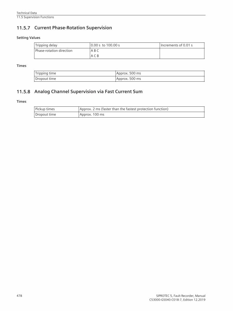
Current Phase-Rotation Supervision
Setting Values
Tripping delay 0.00 s to 100.00 s Increments of 0.01 sPhase-rotation direction A B C
A C B
Times
Tripping time Approx. 500 msDropout time Approx. 500 ms
Analog Channel Supervision via Fast Current Sum
Times
Pickup times Approx. 2 ms (faster than the fastest protection function)Dropout time Approx. 100 ms
11.5.7
11.5.8
Technical Data11.5 Supervision Functions
478 SIPROTEC 5, Fault Recorder, ManualC53000-G5040-C018-7, Edition 12.2019

Operational Measured Values and Statistical ValuesThe following applies to the tolerances of currents and voltages:
• The values apply both to the RMS values and the absolute value and phase angle of the fundamentalcomponents.
• The values were determined for pure sinusoidal signals – without harmonics.
• All measured values have an additional tolerance of 1 DIGIT.
Voltages
VA, VB, VC
Voltage rangeV secondary< 200 V secondary
Secondary rated voltageMeasuring rangeFrequency range
100 V to 125 V(0.1 to 2) · Vrated
49 Hz to 51 Hz at frated = 50 Hz59 Hz to 61 Hz at frated = 60 Hz
Tolerance 0.2 % of the measured value in the above-mentionedmeasuring range
Frequency range (expanded) 45 Hz to 55 Hz at frated = 50 Hz55 Hz to 65 Hz at frated = 60 Hz
Tolerance 0.3 % of the measured value in the above-mentionedmeasuring range
VAB, VBC, VCA
Voltage rangeV secondary< 200 V
Secondary rated voltageMeasuring rangeFrequency range
100 V to 125 V(0.1 to 2) · Vrated
49 Hz to 51 Hz at frated = 50 Hz59 Hz to 61 Hz at frated = 60 Hz
Tolerance 0.2 % of the measured value in the above-mentionedmeasuring range
Frequency range (expanded) 45 Hz to 55 Hz at frated = 50 Hz55 Hz to 65 Hz at frated = 60 Hz
Tolerance 0.3 % of the measured value in the above-mentionedmeasuring range
Currents, Instrument Transformers
IA, IB, IC, 3I0Current range
A secondary< 1.6 Irated
Rated currentsMeasuring rangeFrequency range
1 A, 5 A(0.1 to 1.6) · Irated
49 Hz to 51 Hz at frated = 50 Hz59 Hz to 61 Hz at frated = 60 Hz
Tolerance 0.1 % of the measured value in the above-mentionedmeasuring range
11.6
Technical Data11.6 Operational Measured Values and Statistical Values
SIPROTEC 5, Fault Recorder, Manual 479C53000-G5040-C018-7, Edition 12.2019

Frequency range (expanded) 45 Hz to 55 Hz at frated = 50 Hz55 Hz to 65 Hz at frated = 60 Hz
Tolerance 0.3 % of the measured value in the above-mentionedmeasuring range
Currents, Protection-Class Current Transformer
IA, IB, IC, 3I0Current range
A secondary< 100 Irated
Rated currentsMeasuring rangeFrequency range
1 A, 5 A(0.1 to 5) · Irated
49 Hz to 51 Hz at frated = 50 Hz59 Hz to 61 Hz at frated = 60 Hz
Tolerance 0.2 % of the measured value in the above-mentionedmeasuring range
Frequency range (expanded) 45 Hz to 55 Hz at frated = 50 Hz55 Hz to 65 Hz at frated = 60 Hz
Tolerance 0.3 % of the measured value in the above-mentionedmeasuring range
Currents, Sensitive Ground-Current Transformer
3I0Current range
A secondary< 1.6 Irated
Rated currentsMeasuring rangeFrequency range
1 A, 5 A(0.1 to 1.6) · Irated
49 Hz to 51 Hz at frated = 50 Hz59 Hz to 61 Hz at frated = 60 Hz
Tolerance 0.1 % of the measured value in the above-mentionedmeasuring range
Frequency range (expanded) 45 Hz to 55 Hz at frated = 50 Hz55 Hz to 65 Hz at frated = 60 Hz
Tolerance 0.3 % of the measured value in the above-mentionedmeasuring range
Phase Angle
ΦV °Frequency range 47.5 Hz to 52.5 Hz at frated = 50 Hz
57.5 Hz to 62.5 Hz at frated = 60 HzTolerance ΦV 0.2° at rated voltageΦI °Frequency range 47.5 Hz to 52.5 Hz at frated = 50 Hz
57.5 Hz to 62.5 Hz at frated = 60 HzTolerance ΦI 0.2° at rated current
Technical Data11.6 Operational Measured Values and Statistical Values
480 SIPROTEC 5, Fault Recorder, ManualC53000-G5040-C018-7, Edition 12.2019

Power Values
Active power P W secondaryVoltage rangeCurrent rangeFrequency range
Power factor
(0.8 to 1.2) · Vrated
(0.1 to 2) · Irated
45 Hz to 55 Hz at frated = 50 Hz55 Hz to 65 Hz at frated = 60 Hz|cosφ| ≥ 0.707
Tolerance 0.5 % of Srated in the above-mentioned measuringrange
Reactive power Q var secondaryVoltage rangeCurrent rangeFrequency range
Power factor
(0.8 to 1.2) · Vrated
(0.1 to 2) · Irated
45 Hz to 55 Hz at frated = 50 Hz55 Hz to 65 Hz at frated = 60 Hz|cosφ| ≤ 0.707
Tolerance 0.5 % of Srated in the above-mentioned measuringrange
Apparent power S VA secondaryVoltage rangeCurrent rangeFrequency range
(0.8 to 1.2) · Vrated
(0.01 to 2) · Irated
45 Hz to 55 Hz at frated = 50 Hz55 Hz to 65 Hz at frated = 60 Hz
Tolerance 0.5 % of Srated in the above-mentioned measuringrange
Power Factor
Voltage range (0.8 to 1.2) · Vrated
Current range (0.1 to 2) · Irated
Frequency range 45 Hz to 55 Hz at frated = 50 Hz55 Hz to 65 Hz at frated = 60 Hz
Tolerance 0.02 in the above-mentioned measuring range
Frequency
Frequency f HzRange frated - 0.20 Hz ≤ f ≤ frated + 0.20 HzTolerance ± 2 mHz at V = Vrated or at I = Irated
Range frated - 3.00 Hz ≤ f < frated + 3.00 HzTolerance ± 5 mHz at V = Vrated or at I = Irated
Range 25 Hz to 80 Hz; operational measured values10 Hz to 90 Hz; functional measured values, systemfrequency
Tolerance ± 10 mHz at V = Vrated or at I = Irated
Technical Data11.6 Operational Measured Values and Statistical Values
SIPROTEC 5, Fault Recorder, Manual 481C53000-G5040-C018-7, Edition 12.2019

Statistical Values of the Device
Device operating hours hRange 0 to 9999999 hTolerance 1 h
Statistical Values of the Circuit Breaker
Op.cnt. (operation counter)Range 0 to 999999999Tolerance None∑I Off (sum of the primary currents switched off) A, kA, MA, GA, TA, PA primaryRange 0 to 9.2e+15Operating hours hRange 0 to 9999999 hTolerance 1 hCircuit breaker open hours hRange 0 to 9999999 hTolerance 1 h
Statistical Values of the Disconnector
Op.cnt. (operation counter)Range 0 to 999999999Tolerance None
Technical Data11.6 Operational Measured Values and Statistical Values
482 SIPROTEC 5, Fault Recorder, ManualC53000-G5040-C018-7, Edition 12.2019

CFCTypical response times and maximum number of ticks of the CFC task levels:Task Level Time (in ms) Max. Number of Ticks CP300Fast Event-Triggered < 1 1500Event-Triggered <5 (<10 ms) 12 397Interlocking <5 (<10 ms) 28 656 in totalMeasurement 250
The times describe the response time of a typical CFC chart at the respective task level. The maximum numberof ticks applies to a typical load for the device based on the application template Fault recorder N6: 1/1, 43BI, 33 BO, 20I, 20VThe task level Measurement runs in cycles every 500 ms. All other task levels are event-triggered.In order to estimate the tick consumption of a CFC chart, you can use the following formula:
TChart = 5 ∙ nInp + 5 ∙ nOutp + TTLev + ∑i Tint + ∑j TBlock
where:nInp Number of indications routed as input in the CFC chartnOutp Number of indications routed as output in the CFC chartTTLev 101 Ticks in Fast Event-Triggered level
104 Ticks in Event-Triggered level54 Ticks in Measurement level74 Ticks in Interlocking level
Tint Number of internal connections between 2 CFC blocks in one chartTBlock Used ticks per CFC block (see Table 11-1)
Table 11-1 Ticks of the Individual CFC Blocks
Element TicksABS_D 2.3ABS_R 1.5ACOS_R 6.9ADD_D4 3.4ADD_R4 3.3ADD_XMV 6.4ALARM 1.8AND_SPS 1.1AND10 2.9APC_DEF 1.2APC_EXE 1.0APC_INFO 3.9ASIN_R 1.3ATAN_R 1.2BLINK 1.3BOOL_CNT 2.0BOOL_INT 1.5BSC_DEF 1.3BSC_EXE 1.1BSC_INFO 2.7
11.7
Technical Data11.7 CFC
SIPROTEC 5, Fault Recorder, Manual 483C53000-G5040-C018-7, Edition 12.2019
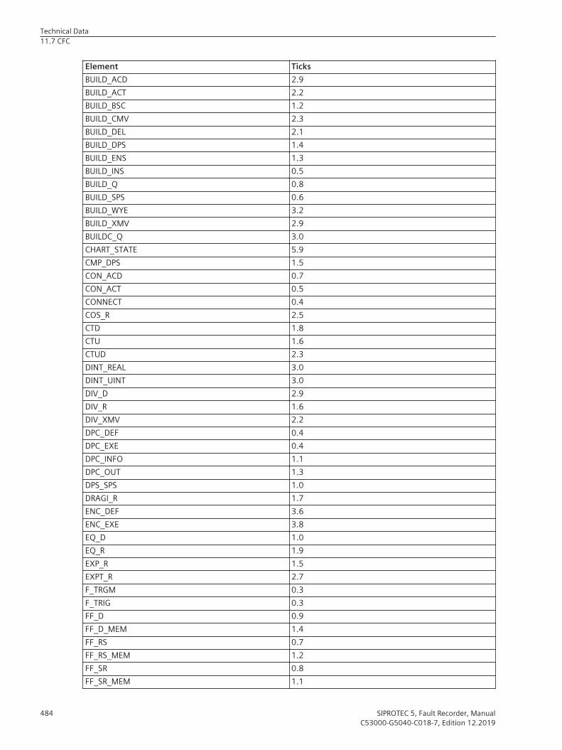
Element TicksBUILD_ACD 2.9BUILD_ACT 2.2BUILD_BSC 1.2BUILD_CMV 2.3BUILD_DEL 2.1BUILD_DPS 1.4BUILD_ENS 1.3BUILD_INS 0.5BUILD_Q 0.8BUILD_SPS 0.6BUILD_WYE 3.2BUILD_XMV 2.9BUILDC_Q 3.0CHART_STATE 5.9CMP_DPS 1.5CON_ACD 0.7CON_ACT 0.5CONNECT 0.4COS_R 2.5CTD 1.8CTU 1.6CTUD 2.3DINT_REAL 3.0DINT_UINT 3.0DIV_D 2.9DIV_R 1.6DIV_XMV 2.2DPC_DEF 0.4DPC_EXE 0.4DPC_INFO 1.1DPC_OUT 1.3DPS_SPS 1.0DRAGI_R 1.7ENC_DEF 3.6ENC_EXE 3.8EQ_D 1.0EQ_R 1.9EXP_R 1.5EXPT_R 2.7F_TRGM 0.3F_TRIG 0.3FF_D 0.9FF_D_MEM 1.4FF_RS 0.7FF_RS_MEM 1.2FF_SR 0.8FF_SR_MEM 1.1
Technical Data11.7 CFC
484 SIPROTEC 5, Fault Recorder, ManualC53000-G5040-C018-7, Edition 12.2019
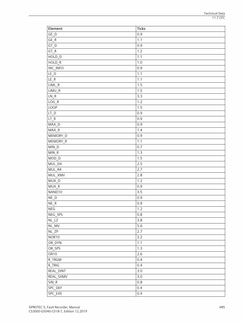
Element TicksGE_D 0.9GE_R 1.1GT_D 0.9GT_R 1.2HOLD_D 1.1HOLD_R 1.0INC_INFO 0.9LE_D 1.1LE_R 1.1LIML_R 1.5LIMU_R 1.5LN_R 3.3LOG_R 1.2LOOP 1.5LT_D 0.9LT_R 0.9MAX_D 0.9MAX_R 1.4MEMORY_D 0.9MEMORY_R 1.1MIN_D 0.7MIN_R 1.3MOD_D 1.5MUL_D4 2.5MUL_R4 2.7MUL_XMV 2.8MUX_D 1.2MUX_R 0.9NAND10 3.5NE_D 0.9NE_R 0.9NEG 1.2NEG_SPS 0.8NL_LZ 3.8NL_MV 5.6NL_ZP 2.7NOR10 3.2OR_DYN 1.1OR_SPS 1.3OR10 2.6R_TRGM 0.4R_TRIG 0.4REAL_DINT 3.0REAL_SXMV 3.0SIN_R 0.8SPC_DEF 0.4SPC_EXE 0.4
Technical Data11.7 CFC
SIPROTEC 5, Fault Recorder, Manual 485C53000-G5040-C018-7, Edition 12.2019

Element TicksSPC_INFO 0.4SPC_OUT 0.4SPLIT_ACD 3.4SPLIT_ACT 1.0SPLIT_BSC 1.3SPLIT_CMV 2.2SPLIT_DEL 2.0SPLIT_DPS 1.0SPLIT_INS 0.5SPLIT_Q 0.7SPLIT_SPS 0.8SPLIT_WYE 2.6SPLIT_XMV 2.1SQRT_R 0.6SUB_D 1.3SUB_R 1.6SUB_XMV 2.4SUBST_B 1.0SUBST_BQ 1.5SUBST_D 1.0SUBST_R 1.0SUBST_XQ 1.4SXMV_REAL 3.0TAN_R 1.1TLONG 2.2TOF 1.0TON 1.1TP 2.5TSHORT 1.9UINT_DINT 3.0XOR2 2.6
Technical Data11.7 CFC
486 SIPROTEC 5, Fault Recorder, ManualC53000-G5040-C018-7, Edition 12.2019