Embed Size (px)
Citation preview

Operating Manual
For the Motor Vessel
Sirocco
Coast Guard Documentation No. 1191342
Hull ID BOY 434720583
Welcome aboard!
We are happy you have chosen “Sirocco” for your vacation. We are sure you will enjoy
cruising the lovely islands of the Pacific Northwest.
We trust this manual will help you become familiar with the boat. If you have questions
about the boat or about places to visit, please do not hesitate to ask the AYC staff.
2
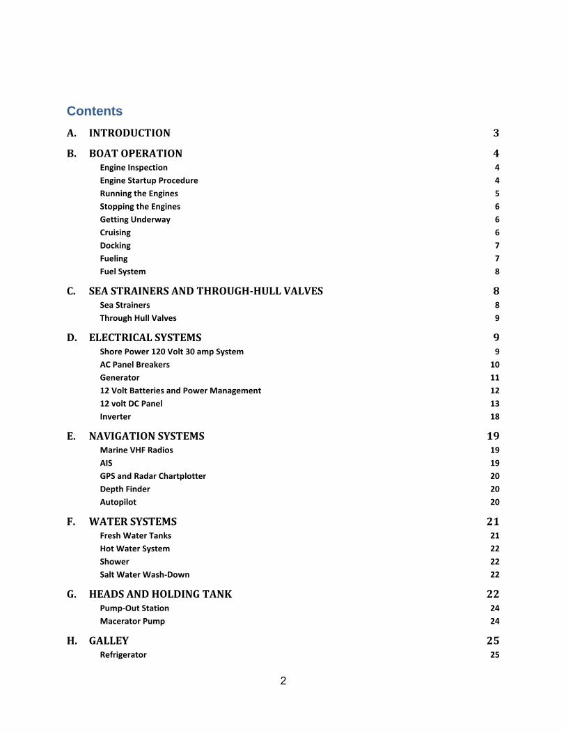
Contents
A. INTRODUCTION 3
B. BOAT OPERATION 4
Engine Inspection 4
Engine Startup Procedure 4
Running the Engines 5
Stopping the Engines 6
Getting Underway 6
Cruising 6
Docking 7
Fueling 7
Fuel System 8
C. SEA STRAINERS AND THROUGH-HULL VALVES 8
Sea Strainers 8
Through Hull Valves 9
D. ELECTRICAL SYSTEMS 9
Shore Power 120 Volt 30 amp System 9
AC Panel Breakers 10
Generator 11
12 Volt Batteries and Power Management 12
12 volt DC Panel 13
Inverter 18
E. NAVIGATION SYSTEMS 19
Marine VHF Radios 19
AIS 19
GPS and Radar Chartplotter 20
Depth Finder 20
Autopilot 20
F. WATER SYSTEMS 21
Fresh Water Tanks 21
Hot Water System 22
Shower 22
Salt Water Wash-Down 22
G. HEADS AND HOLDING TANK 22
Pump-Out Station 24
Macerator Pump 24
H. GALLEY 25
Refrigerator 25

3
Galley Stove 25
I. CABIN HEAT AND THERMOSTAT 26
Diesel Furnace 26
Electric Space Heaters – Use only with Shore Power 26
J. ENTERTAINMENT SYSTEMS 27
AM/FM Stereo Radios 27
TV/VCR 27
K. ANCHORING – USE WINDLASS ONLY WITH ENGINES RUNNING 27
L. BARBEQUE 28
M. DINGHY AND DAVIT CLIPS 29
N. OUTBOARD MOTOR 30
O. SAFETY EQUIPMENT 31
P. SPARE PARTS AND TOOLS 31
Q. END OF CHARTER 32
R. NAN SEA JEAN UPDATE 2016 33
A. Introduction
The Nan Sea Jean is an Ocean Alexander 43 motor vessel built in 1983 by Alexander
Marine Co., Ltd at Kaohsiung, Taiwan, ROC. She has a displacement of 30,000 pounds
with a length of 42 ft 8 in overall, 38 ft 2 in on the waterline, a beam of 14 ft 6in, and a
draft of 3 ft 6 in. She has twin Lehman 120 hp diesel engines with two 25.5 in. props on
2 in. diameter shafts.
The Nan Sea Jean is a tri-cabin trawler with a spacious aft cabin that includes a walk-
around queen bed, lots of storage, a full size shower and private head. The main salon
has a 7-ft settee on the port side and an L-shaped settee on starboard, with a free
standing dining/coffee table. The engine room is below the main salon. The galley is
forward of the main salon down 4 steps where there is a dinette table with booth seating
to starboard of the galley. The forward cabin has 2 bunks to port and a ½ head to
starboard. The heads are vacu-flush.
There is a helm station in the lower main salon, forward on the starboard side and
another helm station on the flying bridge. There is ample deck space above the aft
cabin and the main salon, with room for deck chairs and a small table on the bridge.
The dinghy is kept on davits on the aft swim platform.

4
B. Boat Operation
Engine Inspection
The Nan Sea Jean has two Ford Lehman 120 hp diesel engines, model no. 2715E. The
oil check dip sticks are located on the inboard side of each engine. Remember to check
your “WOBBS” every morning: Water (Coolant), Oil, Bilges (Inspect and Pump-out),
Belts and Sea Strainer.
Before starting the engines,
Check the level of OIL in each engine by checking your dipsticks located on the
inboard side of each engine. Look at the etch marks on each dipstick that
indicate the proper oil level. DO NOT OVERFILL OIL! Only add oil if oil levels are
below the ½ way mark, which indicates that a quart of oil should be added.
Please use a paper towel or oil rag to check the oil levels, not the dish towels!
Check the general condition of the BELTS, HOSES, and FUEL LINES
Observe the glass of each RAW WATER STRAINER for debris. If necessary,
close the seacock, open the strainer cover being careful not to lose the sealing
washer under the wing nut, clean the strainer, and reassemble. Use a bucket to
rinse and clean the strainers; discard debris appropriately. Remember to reopen
the seacock
Ensure the valve on each RAW WATER THRU-HULL is in the ‘open’ position
(lever in-line with valve)
Check the level of COOLANT in the expansion tanks
Check the generator oil and coolant levels after using the generator.
Engine Startup Procedure
Before starting the engines, do your WOBBS inspection described above. Normally,
plan to start the port engine first.
1. Place the BATTERY SWITCH to START, check that the autopilot is off or on
Compass mode. Note: do not move the battery switch when the engines are
running.
2. Place the TRANSMISSION SHIFT LEVERS (black knobs) in the NEUTRAL
(straight up) positions and run the THROTTLE LEVERS (red knobs) up and
down and leave near the IDLE (aft) positions
3. Turn IGNITION KEY on for the engine to be started, the oil pressure warning
buzzer will sound. Start only one engine at a time
4. Press the START BUTTON for no longer than 10 seconds and give the engine
some fuel with the throttle. Release the button when the engine starts. If the
engine does not start after 10 seconds, release the start button and wait a few
seconds before attempting to start the engine. If the engine does not crank over,
check that the corresponding SHIFT LEVER in the neutral position. Engines will
not crank if transmissions are not in neutral.
5
5. After starting the engines, idle the engines at about 800 to 1000 rpm for at least 5
to 10 minutes to warm up the engines; check that oil pressure registers and that
both alternators are charging and both engines have RPMs.
6. Always check that cooling water is exiting the exhaust pipes at the corners of the
stern. If no or low water is coming out, shut the engines down and check the
strainers and valves
7. Turn on the DC panel switches for Radio and the “L”, “R”, and “A” pull-out
switches for the depth finder, Radar/Chartplotter, and Autopilot, respectively.
Then turn on BOTH Furuno units and the Impulse Depth Sounder. Note: if Both
Furuno units are not on, the lower help VHF Radio will alarm loudly after 10
minutes.
8. Idle the engines before placing transmissions in gear.
During warm-up, move the THROTTLE to raise the engine speed to 800 to 1000 rpm on
the TACHOMETER. Warm the engines for at least 10 minutes before engaging
transmissions. Observe the readings of the gauges. The oil pressure will register about
40 PSI. The engine temperature should rise slowly. Check that cooling water is coming
out of the exhaust pipes at the stern of the boat.
Note -- If oil pressure is low, shut down engine, and inspect engine compartment and
look for possible cause (for example, loss of oil.) Caution -- If an engine is overheating
or there is lack of raw water expelled in the engine exhaust, stop the engine
immediately. Recheck the raw water-cooling system to ensure the seacock is ‘open’
(handle in the UP position). Next, check the raw water strainer for debris. Remove the
strainer, clean, re-assemble, and reopen the raw water intake valve (seacock). Restart
the engine and re-check water flow from the exhaust. If water is not flowing properly, the
intake hoses or the RAW WATER PUMP may need to be serviced. Seek help.
Running the Engines
While operating the engines keep the battery switch on the start battery bank. The
temperature gages should be between about 180 and 200 degrees F and the
alternators should charge at >12 to 14 volts. Cruising speed is most economical at
engine speeds of 1500 to 1700 rpm, which will make about 6.5 knots. The depth finder
shows the speed of the boat through the water, while the chart plotter/GPS shows the
speed of the boat over the ground (SOG). The difference between the two speeds is the
speed of the tidal current if present. Engine oil pressure should be over 30 psi, but
NOTE that the port oil pressure often reads high; you can disregard the high reading.

6
Stopping the Engines
Before shutting down, allow the engines ‘idle’ for about 5 minutes to cool them gradually
and uniformly. The time engaged in preparing to dock the boat is usually sufficient. To
turn off the engines:
1. Make sure that the engines are IDLING and the transmissions are in NEUTRAL
and the IGNITION KEY for each engine is in the “ON” position
2. Press the stop button for the engine to be stopped; the engine should stop, if not,
check that the IGNITION KEY is in the ON position
3. After a few seconds the engine oil pressure alarm will sound
4. Turn off the IGNITION KEY to silence the alarm.
5. After engine shut-down, as an option, run the engine room BLOWER FAN for 5-
10 minutes (after switching to the house battery) to cool the engine room and to
keep the heat from the engines from rising into the cabin, especially on a warm
day.
6. Switch the battery switch to the house bank if on mooring or anchor, or to BOTH
if on shore power.
7. Leave Keys in the ignition at all times!
Getting Underway
DISCONNECT and stow the shore power cord (see 110-Volt operations below). Close
the PORTHOLES, WINDOWS, and FORWARD HATCH. Turn on the VHF radios, depth
finder, and both chart plotters. Ready the BOAT HOOKS for quick access and ASSIGN
crew members their various positions to work dock lines and for lookout. After exiting
the marina, idle the engines while crew brings in fenders and lines. Stow fenders and
dock lines securely on the aft deck for passage making. Never cruise with the fenders
out.
Cruising
All close quarters maneuvering should always take place at the upper helm where
visibility is best. Engage the GEARSHIFTS. Ensure the throttles are in the ‘idle’ position
before engaging the gearshifts to avoid transmission damage. Cruising speed is a
maximum of about 1750 RPM. If you run at 1650 RPM you will cruise at 6 to 6.5 knots
and use only 2 gallons of diesel per hour. Your speed will vary depending upon the
weight and load and weather conditions and current. The Nan Sea Jean has a full
displacement hull so there are no trim tabs to put the boat in a “bow down” position.
Note -- Avoid higher engine speeds >1750 RPM as it causes higher engine
temperature, possible damage, and significantly higher fuel and oil consumption with no
significant increase in speed.

7
While cruising turn on the inverter with ONLY the AC “OUTLETS” breaker on to enable
device charging, etc., turn off the inverter before docking or anchoring to preserve
battery voltage.
Docking
Before arriving at the dock, have your crew ready the lines and fenders and give clear
instructions on how you will be docking. Often times your crew will need to step off from
the swim step with the stern line and or the mid-ships line. Another crew member will
need to be at the bow or mid-ships to hand over the next lines.
During docking, use the FLYBRIDGE HELM for greater visibility to the stern. Use the
rudder to assist with turning operations, because the Nan Sea Jean has a substantial
keel, using props only for turning is not adequate.
Fueling
Open the FUEL FILLER CAP(s) located on both sides of the cabin in the walk way at
mid ships with a DECK FITTING KEY which is kept in the lower helm step locker below
the cabin door.
MAKE SURE YOU HAVE THE RIGHT FUEL! DIESEL! DIESEL! DIESEL! MAKE SURE
IT IS GOING INTO THE RIGHT DECK FILL AT MIDSHIPS! DOUBLE-CHECK!
Before pumping fuel, have an oil/fuel sorbs mat handy to soak up spilled fuel. You
should have a rough idea of the number of gallons you will need by the engine hour
indicator (assume about 2.5 gph) as the site tube fuel gauges in the engine room only
register after 110 or so gallons are used. You must listen carefully at the filler deck
fitting while fueling for a change in fill sound.
Place the DIESEL nozzle into the tank opening, pump slowly and evenly, and note the
sound of the fuel flow. Pumping too fast may not allow enough time for air to escape,
which may result in spouting from the tank opening. As the tank fills, the sound will rise
in pitch or gurgle. Pay attention to the TANK OVERFLOW VENT on the outside of the
hull near the tank opening. The GURGLING sound will indicate that the tank is nearly
full. Stop fueling when you hear fuel gurgling up into the filler tube at the top of the tank.
DO NOT TOP OFF. Be prepared to catch spilled fuel from the tank vent on the outside
of the hull and from the filler cap area. Spillage may result in a nasty fine from law
enforcement.
Replace each tank cap and tighten snugly with the deck key. Caution -- Clean up
splatter and spillage immediately for environmental and health reasons. Wash hands
with soap and water thoroughly after fueling.

8
Fuel System
Both engines have Racor primary fuel filters mounted on the fuel tank bulk heads, with
secondary fuel filters on each engine. The starboard fuel valve manifold is for fuel
supply and the port fuel valve manifold is for fuel return of unused fuel back to the tanks.
Under normal conditions all fuel valves will be open and ready for the engines to be
started. Please leave the fuel valves in the ‘on’ positions unless there is a need to close
a valve due to a leaking fuel line, etc. Clear tubing sight gages are located on each tank
forward of the engines. Turn valves above and below the sight gage tubes to the
parallel position to view the fuel levels. Unless the engines have been operated
extensively, the fuel sight gages will typically show full. Please keep the fuel level sight
tube valves in the off (perpendicular) position when not viewing fuel level in the sight
tubes.
C. Sea Strainers and Through-Hull Valves
Sea Strainers
The sea strainers filter out sand, seaweed, and other debris from the sea water cooling
intakes so that the debris does not foul the engine cooling systems. Check the engine
cooling sea strainers daily before start-up to make sure that no seaweed or other debris
are present that could clog the cooling systems.
There are four (4) raw sea water through-hull sea cocks and strainers at the following
locations:
forward of the starboard engine for that engine cooling intake
forward of the port engine for that engine cooling intake
forward engine room on the starboard side for the salt water wash-down system
In the starboard aft deck lazarette for the genset engine cooling water intake.
To check the sea strainer, shine a flashlight through the glass. If you cannot see clearly
through the strainer, the strainer needs to be physically checked. Close the seacock
adjacent to the strainer and remove the top wingnut and cap of the strainer – don’t lose
the white gasket under the wingnut. Lift out the strainer and clean the screen contents in
a bucket of water. Discard the debris appropriately (not in the bilge). Replace the
strainer and the cap and top nut and tighten appropriately. Open the seacock and make
sure that the strainer is not leaking. Keep the seacocks open to insure cooling water for
the engines.
Note: Do not operate in shallow waters less than 6 ft deep or in kelp and seaweed beds
or in such a way that prop wash will stir up sand and debris that will then be sucked into
the sea strainers. Be sure to check the sea strainers if operations in shallow water stir
up mud and sand or after operating in seaweed or sea grass.

9
Through Hull Valves
The Nan Sea Jean has the following through-hull fittings with seacocks.
Port engine raw sea water – engine room forward the port engine
Starboard engine raw sea water – engine room forward the starboard engine
Sea water wash down intake – engine room foreword starboard side
VacuFlush Sanitary System discharge – engine room port side behind hot water
heater
Forward head sea water intake (plugged and abandoned) – bilge below galley
Forward head former discharge (plugged and abandoned) – forward head below
sink
Aft head sea water intake (abandoned) – aft cabin bilge
Aft head former discharge (plugged and abandoned) – aft head below sink
Genset raw sea water intake and sea strainer – aft deck locker starboard side
Engine room bilge pump – forward engine room starboard side hull
Aft bilge pump – aft deck locker at stern transom
Aft Shower sump pump – port side mid ship
D. Electrical Systems
The electrical system is divided into two distribution systems: 110-volt AC and 12-volt
DC. The systems are controlled from the AC ELECTRICAL PANEL and the DC
ELECTRICAL PANEL, which are both located at the helm station in the main cabin. The
BATTERY SWITCHES are located at the top of the DC PANEL. When not connected to
shore power and not running the engines or operating the generator, batteries are
providing all power. Therefore, monitor the use of onboard electricity carefully with your
volt meter located on the DC PANEL and at the MAGNUM CONTROL PANEL, which is
located in the overhead panel at mid ships above the galley.
DC circuit breakers that are “ON” are in the UP position and may be signified by RED
lights, but not all circuit breakers have lights that illuminate, check the switch position.
Turn off electrical devices that are not needed such as the RADIO switch on the DC
panel and the L, RADAR, and A pull out switches for the Depth Finder, FURUNO
Radar/Chartplotter, and the Autopilot, respectively, when not cruising.
Shore Power 120 Volt 30 amp System
SHORE POWER supports all AC equipment and receptacles on board, as well as the
battery chargers. To connect to shore power:
1) Plug the 30 amp POWER CORD into the boat by inserting the connector into the
receptacle and then turning the connector slightly to the right (clockwise) to lock

10
the connector into the receptacle. Screw the keeper ring on the connector to the
right to secure the connection.
2) Plug the POWER CORD into the dock receptacle. Check the power rating/plug
size of the nearest dock receptacle (50 amp, 30 amp, 20 amp, or 15 amp
connectors are all configured differently). If necessary, add a CORD ADAPTER
located in the step locker at the lower helm station. Secure the power cord to
prevent trips and do not let the cord dip into the water. Cords coming off the bow
can be wrapped loosely around the bow line.
3) Turn ON the dock power circuit breaker.
4) At the AC ELECTRICAL PANEL, Turn the AC power selection switch to SHORE
POWER (note that the shorter pointed end of the switch should point to the
desired switch position).
5) Turn on the top row of AC circuit breakers for the outlets, battery charger, water
heater, and microwave. Watch your volt meter for load. If the load exceeds the
rated amperage, you will pop your breaker. If this occurs, wait to turn on one of
your systems (i.e. water heater) until your amps drop. Note that the bottom row of
AC circuit breakers are all spares and not used.
6) Be sure that the INVERTER is turned off on the MAGNUM control panel before
turning AC power on, either from shore power or the generator.
The shore power cord connection is located on the starboard side of the cabin forward
of the cabin door. Connect the shore power cord to the vessel with the shore power
switch on the electric panel in the OFF position. When the shore power cord is
connected, turn on the shore power breaker switch on the dock before turning the shore
power switch at the electric panel to the “shore” setting. When disconnecting the shore
power cord, turn off the individual AC breakers before turning off the SHORE POWER
switch.
AC Panel Breakers
There are AC Panel breakers at the lower helm station and breakers located inside the
lower helm electrical access door. There are 6 AC Panel breakers on the upper bank of
breakers at the lower helm station:
Outlets – turns on 120 Volt outlets
REFR – obsolete, not used with new refrigerator installed in 2013
Stove – obsolete, not used
Battery Charger – obsolete, not used
Water Heater – turn on 120 volts to the water heater to heat water when on shore
power. Note: the water heater also heats the water when the port engine is
operated. Note, turn off the Water Heater breaker when using the inverter!
Microwave – turns on 120 volt power to the microwave.

11
The lower bank of AC breakers is not in use.
The breaker for the main MAGNUM battery charger is located inside the electrical
systems access door behind the lower helm and aft of the galley table bench seat.
Please leave this breaker on at all times. The main battery charger is located under
the aft salon seat below the entertainment cabinet.
Generator
The Nan Sea Jean has a 5.5 KW NextGen (genset). The generator is located in the aft
deck locker at mid-ships. Before starting the generator, be sure that the raw water
seacock is open and that the Generator/Shore Power switch on the AC panel is in the
“OFF” position. (Note that the short pointed end of the switch points to the desired
position, not the long end of the switch handle.)
To START the genset,
1) Hold the PREHEAT/STOP rocker switch on the AC Service Panel to the
PREHEAT (downward) position for about 20 seconds, depending on ambient
temperature, then release the switch back to the neutral (center) position.
2) Move the rocker switch to the START position until the genset starts (about 5 to
10 seconds). Repeat if necessary, but do not crank the starter for over 10
seconds at a time.
3) After the genset is running, turn the AC power selector switch to the left position
pointing to the generator controls by pushing in on the white selector knob to
direct the power to the electrical outlets; Check the Service Panel AC voltage
meter for 120 volt power; there will be a delay of several seconds before AC
power is available.
4) Turn on only those AC breakers that are needed for use with the generator.
5) The Generator has its own isolated batteries for starting the generator, which is
located in the wooden battery box to starboard of the generator in the aft deck
lazarette. The generator batteries are automatically charged when the battery
selector switch is to BOTH during charging
6) Place the Main Battery Switch at the top of the DC panel should to BOTH to
charge both battery banks while the generator is running.
7) Make sure that cooling water is exiting with the exhaust at the stern transom port
side, if cooling water is not exiting the exhaust, shut down the generator and
check the raw water intake strainer and valve.
To STOP the generator,
1. Take the load off the generator by turning off the AC breakers.
2. Turn the AC distribution switch from Generator POWER to OFF.
3. Kill the generator by moving the Start/Stop switch to STOP (down position) and
holding until the generator completely stops.

12
4. Be sure to change the DC battery selector switch back to the HOUSE bank
(Number 1) setting after charging is completed. (See below)
12 Volt Batteries and Power Management
The Nan Sea Jean has a battery switch on the DC control panel that selects between
two 12 volt battery banks. When running the engines, when on shore power, and when
operating the generator, leave the battery switch to the “Both” position.
Battery switch position “1” is the HOUSE BATTERY bank that has two 8D
batteries containing 275 amp-hours each for a total of 550 amp-hours
Battery switch position “2” is the STARTER BATTERY bank that has one 8D
battery containing 275 amp-hours
Note -- Do not change the position of the battery switch while the engines are running or
the alternator diodes will be damaged; change the battery switch position with the
engines off
When at anchor, and after the engines are switched off, turn the battery switch to the “1”
position to use battery power from the HOUSE BANK only. Turn the battery switch back
to “START” before starting the engines and while running the engines. The DC voltage
and amperes being used at any time will be displayed on the volt and ammeter gages
on the DC panel. The voltage of the HOUSE battery bank is constantly displayed on the
overhead MAGNUM control panel.
The HOUSE BATTERY BANK (Battery Switch #1 Position) should be used to provide
power for all DC systems including the automatic bilge pumps while on anchor or
mooring. When disconnected from shore power, all 12-volt devices should be used on
the house battery, which will drain at a rate depending on load. Use electrical devices
only as needed to preserve battery power. The DC voltmeter and ammeter on the DC
panel can be switched between the HOUSE Battery Bank (switch position #1) and the
STARTER BATTERY bank switch position #2) to measure charging or resting battery
voltages.
When the battery banks are being charged, the voltage will read from about 13.1 volts
to 14.4 volts depending upon state-of-charge of the battery bank. When the battery
bank is at rest (that is, not being charged), the voltmeter and ammeter on the Magnum
display will provide an indication of the state-of-charge of the battery bank.
With the BATTERY SELECTION SWITCH set to the START battery with the engines
running, the house bank will be charged automatically by the starboard engine and the
start bank will be charged by the port engine. With the BATTERY SELECTION SWITCH
set to BOTH, both battery banks are charged by the BATTERY CHARGER when
connected to shore power or operating the generator. Be sure that the main Battery
Charger breaker in the access door behind the galley table is always left “ON”.

13
Do not let the batteries discharge to below 12.2 volts to prevent over discharge and
possible damage to the batteries and 12 volt systems. Table 1 lists the approximate
battery voltage and battery charge state.
Table 1. Battery Charge State Voltage
Voltage (Wet Cell Battery) Battery Charge State
12.65 volts 100%
12.47 volts 75%
12.25 volts 50%
11.95 volts 25%
11.70 volts 0%
12 volt DC Panel
Figure 1 shows the DC panel breakers, which are described in detail on the following
pages. The 12 volt DC electric panel has the following breaker switches listed from the
top row, left to right:

14
Figure 1. The 12 Volt DC Breaker Panel
Navigation Light – turns power on to lower helm panel switch that enables the
navigation light switch. Navigation lights are all LED.
Deck Light – turns on small courtesy deck lights located on side decks and bow
deck above the center windshield. Note, not LED lights.

15
Anchor Light – turns power on to lower helm panel switch enabling anchor light
switch. The anchor light is LED.
Spread Light – turns on the spreader lights located on arch at rear of flying
bridge – note these are not LED and use about 20 amps! Use cautiously or when
engines are running only!
Horn – turns power on to helm panels enabling the horn buttons
Wiper – turns power on to lower helm panel enabling the three wiper switches
Panel Light – turns power on to panel lights and cigarette outlets on upper and
lower helms to enable panel gage lights to operate. Also turns on power to the 12
volt adapter plug at the lower helm (looks like cigarette lighter) when the side
panel light is pushed in – note that there is an on/off toggle switch also located on
the lower helm panel and there is also a switch on the panel light adapter that fits
in the outlet. The upper helm Panel switch turns on the upper helm gage lights
Salon Light – turns power on to salon lights
Note additional salon light switches that are typically behind curtains:
Wall switch aft of starboard entry door turns on ceiling light over lower
helm
Wall switch on port wall below brass wall light near bar – turns on the
brass wall light and the ceiling light above bar
Wall switch on port wall behind couch curtains – turns on both aft salon
ceiling lights and the starboard brass wall light, which each have
individual on/off switches
AFT Cabin Light – turns on lights to the aft cabin
Note additional light switches to the aft cabin area:
Wall switch on companionway to aft cabin turns on 3 ceiling lights
Wall switch on port side of shower door turns on ceiling light in shower
Wall switch on wall starboard side of aft head door turns on light in
head
Wall switches beneath aft cabin brass wall lights turn on the brass
reading lights, which also have switches
FWD Cabin Light – turns on lights to the forward cabin area
Note additional light switches to the forward cabin area:
Wall switch to starboard of companionway above dinette turns on the
galley ceiling light and light over galley table
Wall switch below galley sink turns on fluorescent light behind sink
counter. NOTE not LED, uses a lot of amperage
Wall switch below galley sink turns on night light at galley floor. NOTE:
lights that are not LED, use more battery power.

16
Wall switch in fwd cabin to left of fwd head door turns on the forward head
ceiling light
Wall switch in fwd cabin below bunks turns on night lights at floor
Fwd cabin brass bunk lights have individual switches.
Inter Telephone – turns power on to the telephone intercom system. Note
number codes at lower helm for ringing the different telephones
Windscreen Washer – turns power on the windshield fresh water switch that is
located to starboard of the lower helm wheel.
Outlet – turns power on the galley stove gas system and to the 12-volt outlets
located under bunks in fwd cabin, under dinette table, in aft cabin starboard wall
behind head door, and in upper helm dashboard to left of starboard access
doors. The upper helm stereo located in starboard dash locker is also powered
by the Outlet switch. When onboard, keep the Outlet Switch turned on.
REFR – turns 12 volt power on to the refrigerator
FWD Head – turns power on to operate the VacuFlush system for the fwd head –
note also that there is an on/off toggle switch in the fwd head
AFTER Head - turns power on to operate the VacuFlush system for the aft head
– note also that there is an on/off toggle switch in the aft head
RADIO – turns power on to the VHF radios at both helms
STEREO – turns power on to the stereo and television cabinet located in the
salon
FW Pump – turns power on to the fresh water pump. There is a fresh water deck
spigot located at the stern deck to port of the salt water wash down spigot
SW Pump – turns power on to the salt water wash-down pump. Salt water wash
down spigots are located at the bow to starboard of the windless and the stern to
port of the fresh water spigot.
ENG RM Bilge P – turns power on to the engine room bilge pump – note LEAVE
ON AT ALL TIMES. Test by moving temporarily to MANUAL. The bilge pump
below galley is connected to the engine room bilge pump and operates
simultaneously with the engine room bilge pump.
AFTER Bilge P – turns power on to the aft bilge pump located in aft cabin – note
LEAVE ON AT ALL TIMES. Test by moving temporarily to MANUAL.
Sump Pump 1 – shower sump pump 1 – note LEAVE ON AT ALL TIMES
Sump Pump 2 – shower sump pump 2 - note LEAVE ON AT ALL TIMES
Spare
Anchor Windless (Labeled “Anchor”) – Turns power on to the anchor windless
breaker. If windless has no power, check the main windless breaker, located
adjacent to the large electrical access door aft of the galley settee. Spare

17
Holding Tank P - turns power on to macerator pump to pump out holding tank,
be sure that through-hull sea cock is open to port of hot water heater in engine
room
Eng RM Blower – turns on the engine room blowers to vent engine room air
Eng RM Light – turns on the engine room lights – be sure to turn off when not in
use
Six Auto/Manual Toggle Switches for Bilge and Sump Pumps – keep the 6
toggle switches in the AUTO position – check operation by moving to manual
temporarily.
Switch #1 is the forward bilge pumps,
Switch #2 is the aft bilge pump
Switch #3 is spare
Switch #4 is the aft shower sump pump
Switch #5 is spare
Switch #6 is spare
“L” Pullout Switch – turns power on to the DEPTH FINDER
“R” Pullout Switch – turns power on to the Furuno Radar/GPS system
“A” Pullout Switch – turns power on to the Autopilot
The 100 Amp windlass breaker is located on the forward facing wall adjacent to the
large electrical access door just aft of the galley dining table. Leave on during normal
operations.
Figure 2 shows the lower helm panel switches that control the following lights and
functions: Similar switches are on the upper helm panel.
Navigation lights (be sure DC panel breaker is also on)
Horn
Anchor light (be sure DC panel breaker is also on)
Wipers (be sure DC panel breaker is also on)
Fan
Panel lights (light that plugs into the cigarette adapter at each helm), and the
upper helm Panel switch turns on the rudder indicator
Compass lights

18
Figure 2. Lower helm panel switches.
Inverter
Turn the inverter off before anchoring or using the generator or connecting to shore
power. Turn off the inverter by pressing the “INVERTER” button at the lower left corner
of the MAGNUM POWER remote control and monitor, which is located at the lower
helm overhead panel at midship.
The battery charger is equipped with an inverter that provides 120 volt power, 1500
watts maximum to the 120 volt panel when not connected to shore power or on genset
power. When operating the inverter, only the AC OUTLET breaker should be turned on,
all other AC breakers must be off. Generally only use the inverter while running the
motors as the current draw will quickly deplete the batteries. Turn off the inverter if
connected to shore power or while running the generator. Note: the microwave takes a
lot of battery power and should be used on inverter when running engines or with only
the microwave AC panel switch on. Use the microwave for brief periods only while using
the inverter.
19
On Anchor - use the inverter only for short periods of time, be sure the battery switch
set to the #1 house bank and make sure that all the 120 volt breaker switches are in the
off position except for the OUTLETS breaker, and that any electric heaters or high
power 120 volt appliances are unplugged or off.
Turn on the inverter by pressing the “INVERTER” button at the lower left corner of the
MAGNUM POWER remote control and monitor, which is located at the lower helm
overhead panel at mid ships. With the inverter on, ONLY turn on the 120 volt breaker for
the AC OUTLETS – unplug any electrical devices that are not to be used if outlets are
turned on. Note that the inverter will supply a maximum of 1000 watts, so be sure that
no appliances or devices will use anything close to that amount of power. Do not use
the inverter for extended periods as the batteries will be quickly drained. Use of the
inverter for larger power devices such as hair dryers is discouraged; use the generator
instead.
Underway - The inverter can be used while cruising with engines on to charge
computers and devices, etc. Be sure that only the OUTLETS AC switch is on. Don’t use
the AC hot water heater while using the inverter; the hot water will heat off the port
engine cooling water.
E. Navigation Systems
Marine VHF Radios
The lower helm has a Standard Horizon Gx 1250 Marine VHF radio with digital select
calling (DSC) and automated identification system (AIS). The upper helm has a Uniden
marine VHF radio. Helmsmen should monitor channel 16 during operation of the vessel
and follow marine VHF radio protocols. Use lower power to transmit when in port or
when issuing a security when transiting a narrow passage. An auxiliary hand-held
marine VHF radio is located on a charger base in the aft port salon. Monitor VHF
channel 16 while underway and follow proper marine radio protocols. Do not attempt
conversations on channel 16 or the Coast Guard will intervene; go to a working channel
after making contact on channel 16. Press and hold the CLR/WX button on the lower
helm VHF radio for a few seconds to access the marine weather radio channels.
AIS
The lower helm VHF radio is equipped with automatic identification system (AIS) and
marine mobile service identity (MMSI). The AIS is automated and does not need to be
turned on separately when the radio is powered up. The range for the AIS is about the
same as for the VHF radio signals – which is approximately line of sight. Other vessels

20
with AIS will show on the small circular display on the radio screen and the range of the
display can be changed by pressing the range soft button twice and selecting the
desired range. The AIS data are integrated with the Furuno Chart Plotter. The images of
other vessels on the Furuno Chart Plotter are elongated triangles showing the location,
bearing line, and track line of each vessel that is broadcasting AIS. The same
information from the Nan Sea Jean will be displayed on the screen of any other vessel
with AIS. Both of the Furuno chart plotters at the lower helm and upper helm stations
must be “ON” for the AIS to be displayed on the chartplotters. Move the cursor ball over
an AIS target on the screen to see additional information about vessels – press the
center button to return the display curser and boat location to the center of the chart
screen after moving the cursor.
GPS and Radar Chartplotter
The Nan Sea Jean is equipped with two Furuno model 1834C chartplotters with a 24”
radome and a 4.0 KW transmitter with 36 NM radius, integrated with GPS, marine
navigation charts, AIS, and depth finder into a 10.4 inch color LCD display at both helm
stations. Press the Power/Brill button to turn the Furuno GPS chart plotter on and off.
The Select the display button and select between several preset displays for the chart
plotter/radar/depth information. Press the range +/- toggle switch to expand or reduce
the scale of the views, depending on which display is active. The roller-ball mouse
moves the cursor on the screen; press the large selector button in to make selections.
Remember that operating in fog, at night, or in extreme weather conditions is not
allowed. A hand-held Garmin GPS Map 76C and a Garmin GPS Map 76 are located in
the drawer beneath the lower helm seat for emergency backup use.
Depth Finder
After enabling power to the depth finder with the “L” pullout switch on the DC panel,
press the power button to turn on the Impulse 2000+ Fishfinder, which is located to the
right side of the lower helm station, and then select the Digital display mode. The depth
finder displays the depth and the speed through the water in the Digital mode. The
Furuno system has an independent depth system that is displayed in on-screen data
fields in the plotter views on the Furuno system. The Impulse depth finder displays the
speed of the vessel through the water, which can be compared with the speed over
ground from the Furuno GPS to determine the relative speed of any current that the
vessel may be experiencing.
Autopilot
The autopilot is a Robertson AP 100 DC system. The autopilot is powered on by the “A”
pullout switch on the DC panel. The operations manual is located in the boat systems
binder. When not using the autopilot keep in the “OFF” or “COMP” compass mode. The
modes include:

21
OFF – autopilot is off
COMP – compass mode, the autopilot screen shows the compass heading in the
readout
PWR ST – power steering mode, the autopilot can be used to steer the boat but
will not keep a course – DO NOT USE
AUTO – auto pilot mode, the autopilot will keep the course set in the readout –
Use this setting
NAV – navigation mode, do not use, not programmed for use.
To use the autopilot, steer the boat on the course desired, and turn the Mode selector
switch to AUTO. Wheel steering is disabled and the ship will be steered on the course
set in the autopilot readout. Turn the Course knob to select the magnetic course to be
steered. The rudder selector should be set to MID2 for normal autopilot use.
Turn the autopilot to off or the COMP mode before entering harbor or for dodging
and manual course corrections while underway.
There is a remote autopilot control in the flying bridge starboard dash locker that can be
used to change course direction and place the autopilot in standby by pressing the
DODGE button. When reengaging the Auto Pilot from DODGE, the boat will return
immediately to the original heading prior to engaging DODGE. Turn the Autopilot OFF
or to Compass prior to reengaging if the heading was drastically changed. The remote
control will display an “A” and the course when in autopilot mode, and will display a
flashing P when in dodge mode. However, the remote cannot be used to change
autopilot modes, which can only be done at the lower helm station. Use the autopilot
with extreme caution and be sure that the autopilot is off or in compass mode when
starting the engines. The helm station wheels will not function when the autopilot
is in power steering or auto mode! Do not have the autopilot on while in
anchorages or marinas.
F. Water Systems
Fresh Water Tanks
The fresh water tanks are located beneath the aft cabin birth. There are two tanks that
hold 100 gallons each. The tanks are filled from the aft deck fresh water filler. Use the
deck key to open the fill cap. The tank vents are located on the stern beneath the swim
step. Fill the water tanks before departing and after returning the boat. Do not fill water
and diesel at the same time!
The FW Pump switch is located on the DC panel, which will turn on the fresh water
pump. The fresh water pump is located in the engine room behind and to port of the hot
water heater. Turn the pump switch off when departing the boat. The FW pump must be
on to use the VacuFlush heads. If the water pump runs constantly, you are either out of
water or might have an air lock and need to bleed the system by opening a faucet. If
22
you run out of water, SHUT OFF the FW PUMP switch on the DC panel and the HOT
WATER HEATER switch on the AC panel. Serious damage can occur!
Note: if there is no water pressure, turn the FW switch on the DC panel off and on
again, wait a few moments and recheck for water pressure, let it run for a bit. The fresh
water pump is located in the engine room port side behind the hot water heater.
Hot Water System
The hot water system is a 6 gallon hot water tank that is located in the engine room
forward of the port engine. The hot water tank is heated when the port engine is running
and/or by switching on the 120 volt panel switch for the Hot Water Heater when on
shore power or when operating the generator. Do not heat water with the inverter on!
Shower
The shower is located on the port side forward of the aft cabin. Be sure the fresh water
(FW) pump switch and the shower sump pump switch on the DC panel are on before
using the shower. Also be sure that the shower floor drain strainer is clear of debris to
allow the shower to drain to the shower sump pump. Take only very short “boat”
showers (turning off water between soaping up and rinsing – use the on/off valve at the
shower head). To keep shower tidy wipe down the shower stall and floor. Check for
accumulation of hair in the shower and sink drains.
Salt Water Wash-Down
The salt water wash-down spigots are located at the bow near the anchor roller and on
the lower aft deck. At the aft deck the left spigot is salt water and the right spigot is fresh
water. The salt water pump, through-hull valve, and sea strainer are located in the
engine room forward the starboard engine. The salt water pump is turned on by the SW
Pump switch on the DC panel. Keep the SW Pump switch off when not needed. Rinse
the anchor and chain every time it is used to keep mud and seaweed out of the anchor
locker, which drains to the bilge, mud and slime from the anchor chain could foul a bilge
pump.
G. Heads and Holding Tank
It is important that every member of the crew be informed on the proper use of the
MARINE TOILET. The valves, openings, and pumps are small and may clog easily.
Please do not put anything but human waste in the toilets – Please put toilet
paper in the head waste cans and dispose of toilette paper with trash. If the toilet
clogs, it is YOUR RESONSIBILITY!
Both heads are electric VacuFlush heads that use fresh water for flushing. Turn on the
following switches to operate the heads:

23
DC panel switches for the FWD and AFT Heads
DC panel switch for the FW pump,
The toggle switches located below the sinks in each head.
To flush the heads, simply push down the foot lever for 3-5 seconds to evacuate the
bowl and activate the vacuum system. Let the foot lever snap back to original position to
ensure the head valve closes. You will hear the fresh water pump operate for about 5
seconds and the vacuum pump operate for about 10 seconds after flushing the heads.
The head holding tank capacity is 35 gallons. The holding tank is located beneath the
galley floorboard. The tank can fill up quickly with use and should be emptied at least
every 2 to 4 days with a family of 4 using the heads. With an overfilled tank, it is
possible to break a hose, clog a vent, or burst the tank. The result will be an
indescribable catastrophe and an EXPENSIVE REPAIR and CLEANUP to you. Keep an
eye on the tank level and empty the tank EVERY THREE DAYS to avoid this problem.
The holding tank is emptied in one of two ways, as selected by the position of the WYE
VALVE, which is located in front of the tank as shown in Figure 3. The figure shows the
WYE Valve in position to empty the holding tank to the deck fitting, as indicated by the
arrow shown pointing to the right. Move the gray valve selector to cover the right arrow
and the left arrow indicator is uncovered, which will direct the flow to the macerator
pump, which is located at the far left in the photo.
Figure 3. Holding tank WYE valve in position discharge to the deck fitting.

24
Follow the following directions for emptying the waste holding tank.
Pump-Out Station
Make sure that the WYE VALVE is positioned as shown in the above photo
showing the discharge arrow to the starboard to discharge to the deck fitting.
Remove the WASTE DECK CAP located on the bow deck to port of the windlass.
Use the deck key, which is located in the lower helm step locker.
Insert the pump-out nozzle securely into the waste opening and hold securely in
place. Double-check the deck fitting seal with the pump-out nozzle to insure a
tight seal! Turn on the dockside waste pump and open the in-line valve located
on the pump-out hose. View waste discharged via the clear fitting at the hose
handle.
When pumping is finished, close the valve on the handle and remove the pump-
out nozzle.
If there is a fresh water hose on the dock, rinse the tank by adding about 2
minutes of water into the holding tank through the deck fitting, then re-pump the
holding tank to leave the tank rinsed for the next charter. (This eliminates head
odors.)
Repeat and flush-out the holding tank twice.
After pumping out, remove from pump-out hose from the waste cap and turn off
the dock-side vacuum pump.
Securely replace the waste cap at the deck fitting.
Macerator Pump
The holding tank’s contents can be discharged with the MACERATOR only in open
water locations in Canadian waters – not in marinas or high-traffic areas. The macerator
pump is located near the holding tank beneath the galley floor, as shown at the far left in
Figure 3. The WYE VALVE at the outlet of the holding tank must be repositioned to
show the arrow pointing to the left (Port) so outflow will pass to the macerator.
The macerator overboard through-hull valve is located in the engine room to port behind
the hot water heater. Be sure the through-hull valve is open before operating the
macerator.
To MACERATE WASTE OVERBOARD
Turn WYE VALVE so valve handle points to starboard and the arrow to port
shows (opposite as shown in above photo)
Check that THROUGH-HULL VALVE behind the hot water heater in engine room
is open

25
To operate the macerator pump, turn on the “Holding Tank P” switch on the DC
Panel and listen for the macerator pump sound. Open galley floor and watch the
level in the holding tank using a flashlight held to the top of the tank. When the
level is down to the outflow level and the pitch becomes higher, the tank is
empty. Do not run the macerator pump for longer than needed, and usually not
longer than about 1-2 minutes at a time.
Check for discharge on the port side at mid-ship.
Turn off “Holding Tank P” switch on DC Panel
Close Through-Hull Fitting
Return WYE VALVE to Deck fitting setting as shown in above photo.
H. Galley
Galley storage is located in the galley lockers and in the locker above the dinette and
under the aft dinette seat. There is a large galley stowage area located beneath the
counter to the right of the galley sink where a removable bin doubles as an ice box.
Additional dry storage is located under the port settee in the salon.
Refrigerator
The refrigerator operates only on the 12 volt DC system by turning on the REFRIG
switch on the DC panel. Note that the Refrig switch on the AC panel turns on an AC
outlet behind the refrigerator, but does not supply voltage to the new refrigerator that
was installed in 2013. The refrigerator uses about 6 amps/hr, and is a major power drain
on the house batteries when not running the engines or when not on shore power, as
when on anchor/mooring. So monitor the batteries accordingly. The house batteries
should provide adequate power for the refrigerator and other general uses for up to 24
hrs, but use power miserly when on anchor. When using the refrigerator, the batteries
should be charged by running the engines or the genset daily when cruising. Turn off
the refrigerator on cool nights to preserve batteries.
Galley Stove
The galley stove is a 3-burner propane stove. The stove is operated via the following
steps:
1. Open the valve on the propane tank located in the port side dash locker on the
flying bridge. The tank valve will need to be opened before using the galley
stove.
2. Turn on the OUTLETS switch on the DC Panel.
3. Turn on the propane safety gas shut-off valve located on the port galley wall to
the right of the stove. The DC panel switch for OUTLET needs to be on for the
propane valve switch to work. A red light will glow next to the valve switch when
26
the propane gas safety valve is open. When the galley stove is not in use, the
galley stove propane switch must be turned off.
4. Light the stove by pushing in on the appropriate burner knob and turning left 90
degrees to the automatic light setting. You will hear the tick, tick of the automatic
lighter, release the knob when the burner lights and adjust the flame as
appropriate by turning the knob further to the left. Hold the knob in for a few
seconds after lighting a burner for the thermocouple to warm up.
5. The oven can be lighted similarly, be sure the oven is empty before lighting.
When finished cooking
1. turn off gas at the stove
2. turn off the safety gas switch on the galley wall
3. turn off the valve at the gas bottle when departing vessel.
I. Cabin Heat and Thermostat
Diesel Furnace
Nan Sea Jean is equipped with a Webasto diesel forced air heating system that
provides heat in the same way as a household furnace. The control panel for the
heating system is located in the salon on the port side forward the settee and below the
bar. Set the thermostat to the desired temperature and place the on/off switch to the
“ON” position for heat. There is no panel switch for the heater, so please turn off the
heater switch when not needed. As with the refrigerator, the heater draws 5 to 10
amps/hr and will cause a significant drain on the batteries, so monitor batteries when
using the heater on anchor/mooring.
Check The furnace EXHAUST PORT, located on the port side hull at mid-ship, for any
obstruction such as fenders or lines. Do not block this opening when operating the
furnace. Heat from the exhaust will damage fiberglass or rubber. Once the heater is on,
allow it to run for at least 15 minutes before turning it off. Turn ‘OFF the furnace heater
by turning the switch to the “OFF” position.
Electric Space Heaters – Use only with Shore Power
Several small ELECTRIC SPACE HEATERS are available to heat the cabins when
connected to shore power. One heater is located in the forward cabin, another is
available in the aft cabin, and a third is available for the main salon. Make sure the AC
outlet breaker on the AC panel is on and the shore power cord is deployed as described
in the section for SHORE POWER. Be sure to keep combustibles away from the heater
to prevent fires. In addition to the space heaters, two dehumidifiers are located onboard
to keep humidity levels down; one is in the forward cabin, and another in the aft cabin.
Do not use electric heaters while using the inverter!

27
J. Entertainment Systems
AM/FM Stereo Radios
A Panasonic AM/FM/CD/USB/IPod-ready Stereo radio with remote is located in the
upper part of the entertainment cabinet, which is located at the aft of the main salon.
Turn on the STEREO breaker on the DC panel to operate the entertainment systems.
The stereos operate like a normal car radio. There are two speakers (stereo) in the
entertainment cabinet, two speakers in the front of the main salon, and two speakers in
the aft cabin. The FADER control directs sound between the main solon speakers and
the aft cabin speakers. The BALANCE controls the sound distribution in the left and
right side speakers.
A Sony AM/FM/CD/AUX input stereo radio is located in the flying bridge dash cabinet
inside the starboard access doors. This stereo is powered from the “OUTLETS” DC
panel switch and provides sound to the four speakers on the bridge.
TV/VCR
A flat panel TV/DVD with remote is located in the entertainment cabinet. To use, be
sure the STEREO breaker on the DC Panel is switched on. There is no TV antenna, so
the TV only functions as a standard DVD player. Insert a DVD on the right side of the
panel and select DVD to play DVDs.
K. Anchoring – Use windlass only with Engines running
The primary working anchor at the bow is a 35 lb Danforth attached to 275 ft of chain.
When the anchor is stored on the bow roller, keep the anchor secured to the windlass
cleat using the clip line. The Nan Sea Jean is equipped with a bow windlass for letting
out and retrieving the anchor. The anchor windlass has a 100 amp breaker on the back
wall of the lower helm above the dinette and a DC Panel switch; both must be on to use
the windless. There are two foot switches on the foredeck and a remote switch on the
flying bridge for operating the bidirectional windless motor. The windlass clutch handle
(for manual operation only) and anchor handling gloves are stowed in the lower helm
step locker below the salon door. Anchor chain is automatically stowed in the forward
anchor locker through an opening in the deck below the wildcat.
Let out sufficient ANCHOR RODE, at least 3:1, before setting the anchor. Colored
markers are placed at 30 ft from the anchor indicating the amount of rode that is out. If
the anchorage is crowded put down at least a 3 to 1 scope (60 feet for 20 feet of water),
set the anchor in with a short burst from the engine at idle. Then let out additional scope
dependent upon conditions.

28
Before raising the anchor, ALWAYS start the engines as the windlass uses large
amounts of power. Operate the windlass to retrieve chain as the boat moves toward the
anchor, to take up slack line. Give the windlass short rests as you are pulling up the
anchor. DO NOT LUG the WINDLASS!!! As the anchor rises, be careful not to allow it to
swing against the hull. Wash down the chain and anchor with the salt water hose at the
bow as the chain and anchor come aboard. Place yourself in position to guide the
anchor onto the roller. Do not use the windlass to slam the anchor into the final position.
Use short bursts of the windlass to position the anchor on the bow roller and pull the last
few inches of anchor chain in by hand.
Make sure that the anchor is properly seated on the bow roller. The anchor shaft should
be all the way aft on the bow roller and not sticking out forward. Reattach the anchor
line to the bow cleat after the anchor is shipped and set the wildcat brake and tighten
the wildcat clutch. Close the plastic covers on the FOOT PEDAL CONTROLS and turn
OFF the ANCHOR WINDLASS breaker switch on the DC Panel when not using.
A backup 45 lb CQR anchor that can be used replace the primary anchor, and a 20 lb
Danforth stern anchor are located in the aft deck port side locker. The stern anchor has
50 ft of 5/16” chain and 200 ft of 5/8 in. nylon rode. A dinghy clamshell anchor with 10 ft
of chain and nylon rode is also located in the aft deck locker.
L. Barbeque
The BARBECUE is located on the port side of the aft cabin deck. A propane gas line
from the propane tank is located in the port inspection hatch on the aft flying bridge.
Connect the gas line to the barbeque and follow all procedures for use of the galley
stove.
1. Open the valve on the propane tank located in the port side dash locker on the
flying bridge. The tank valve will need to be opened before using the galley
stove.
2. Turn on the OUTLETS switch on the DC Panel.
3. Turn on the propane safety gas shut-off valve located on the port galley wall to
the right of the stove. A red light will glow next to the valve switch when the
propane gas safety valve is open. When the galley stove and BBQ are not in
use, the galley stove propane safety switch must be turned off.
4. Attach the propane line to the BBQ by inverting the control connector 180
degrees and pushing in the connector, then revert the control unit to the normal
operating position.
5. Light the BBQ by pushing in on the control knob and turning to open the gas flow.
Press the lighter switch to light the burner or use a long-stem butane lighter.
Adjust the gas knob to the desired flame height.

29
6. A cutting board accessory tray is stored inside the BBQ, remove before lighting
and attach to the front of the grill.
There is also a regulator for use with disposable propane bottles stowed in the main
salon locker below the bar top. The barbecue generates a lot of heat and cooks hot and
fast. When finished, please check the grease collector at bottom of grill and clean as
needed so grease does not flow to the decks. Clean thoroughly with a paper towel
before storing to prevent grease and dirt soiling the boat. When finished cooking cover
the BBQ and be sure to shut down the propane system:
1. turn off gas at the stove and remove the gas line
2. replace gas line into inspection hatch and secure hatch cover
3. turn off the safety gas switch on the galley wall
4. turn off the valve at the gas bottle.
Note: There is a spare 5-gallon propane bottles in the propane locker with an adjustable
wrench for attaching to the bottles to the propane system. Propane is not supplied by
AYC. You will need to refill the tanks as needed. Caution -- For safety reasons, do not
store an opened propane bottle within the salon or engine compartment. Chances are
these will leak slightly once opened and propane gas could settle into low spaces. Store
these bottles in the bridge cabinet. Ensure gasoline and flammable materials are not
near the barbecue.
M. Dinghy and Davit Clips
The dinghy is a 10 ft AB ultra light hard bottom inflatable. The dinghy is rated for up to 5
adults. Oars are located on the upper aft deck and the air pump is located in a seat
locker on the flying bridge. The dinghy is attached to the aft swim step with davits that
enable quick release and attachment of the dingy with the boat. Two metal rod stand-
offs are attached to the stern of the Nan Sea Jean that attach to the upper inflatable
pontoon of the dinghy when stored upright on the davits. A hand ratchet pulley is
located on the aft cabin deck that attaches to the D-ring on the aft dinghy pontoon for
easily hand cranking the dinghy up and down on the davits. There is a lever on the
handle of the pulley that reverses the action of the pulley so that it winches the dinghy
both up and down.
To deploy the dinghy, clip the snap clip of the DINGHY WINCH LINE to the D-RING
near the upper oarlock on the dinghy inflatable pontoon. Holding the dinghy in place
with the WINCH LINE and the dinghy BOW LINE, detach the STANDOFF BARS from
the dinghy, and lower the dinghy with the DINGHY WINCH line into the water, noting
that the dinghy gets heavier as it nears the water.
30
Retrieve the dinghy by attaching to the davits and connect the WINCH LINE snap clip to
the D-RING, and winch the dinghy into the upright position. Reattach the metal
STANDOFF BARS, and secure the PAINTER to a stern cleat and the WINCH LINE to
the winch while cruising.
Attach the oars to the oar locks on the dinghy by pushing the locking pin into the locks
while the oar is in a position with the oar handle extending outward with the oar end in
the center of the dingy. Rotating the oar to operating position will lock the oar in place.
Remove the oars from the oar locks by similarly rotating the oar 180 degrees from the
normal operating position with the oar inboard and the handle outboard. Remover the
oars from the oar locks while the dinghy is stowed on the davits and when towing the
dinghy. Do not tow the dinghy with the motor mounted on the dinghy.
When towing the dinghy for short distances, always keep it tight to the boat so that
when you slow down or stop the painter will not fowl in a prop. Assign a crew member
as the “dinghy” person to be responsible for taking up slack. You don’t want to wrap the
painter around a propeller.
N. Outboard Motor
The outboard dinghy motor is a 4 stroke 5 hp Lehr that operates on propane gas. The
outboard motor is stored on a mount on the upper aft deck next to the steps to the flying
bridge. Spare propane bottles and spare oil are located in the port side aft seat locker
on the flying bridge. The combination lock code for the outboard padlock is 0060. The
motor should run about 1 hr on a small bottle of propane gas, but be sure to take spare
bottles in the dinghy with you in case the propane runs out.
To start the outboard,
1. Check the oil level at the dipstick beneath the outboard cover.
2. Be sure there is a small propane bottle installed in the aft end of the motor or that
a gas bottle is attached via a gas line to the front of the motor.
3. Be sure the red dead-man key is in position.
4. Be sure the transmission lever is in the NEUTRAL position, or the starter will not
turn the motor over. The forward and reverse lever is on the starboard side of the
motor.
5. Move the throttle position up a few clicks to start.
6. Take the slack out of the pull rope and PULL the starter rope. Because the
propane gas evaporates out of the carburetor, it may take several pulls to start.
7. When the engine starts, adjust the throttle to high idle to warm up for a few
seconds.

31
8. To stop the outboard, press the red stop button, it is not necessary to remove the
red dead-man key at any time.
O. Safety Equipment
SAFETY should be paramount in your daily cruising. A MAN OVERBOARD DRILL
should be discussed and practiced with a life jacket. Remember your lifejackets are
stowed in the starboard bridge seat lockers. A few should always be out and ready.
Your flares and safety equipment are located in the main salon locker below the bar.
Nan Sea Jean is equipped with two AUTOMATIC BILGE PUMPS. The master switch for
each pump is located on the DC panel. Normally, the bilge pump switches will be left in
the AUTO position. You may occasionally hear the pump operate due to condensation
and water from the shaft log accumulating in the bilge.
There is an EMERGENCY TILLER located in the aft deck locker, with a through-deck
fitting over the port rudder shaft. Be sure the AUTOPILOT is OFF or in COMP mode or
the hydraulic wheel steering at both helms will not operate. However, if the hydraulic
steering fails for some reason, the EMEGENCY TILLER can be used to steer the boat.
LIFE JACKETS are located in the starboard seat locker on the flying bridge
FIRE EXTINQUISHERS are located on the engine room door, the galley dinette
wall, and in the aft cabin. Spare fire extinguishers are located in the salon
starboard salon bench storage.
FIRST AID KITS are located in the forward and aft head cabinets
A LIFE SLING and a throw able LIFE SAVING RING are located on the aft deck.
The propane tank is located on the port side of the flying bridge dash locker.
Keep the tank valve off when not in use. A spare propane tank is also available in
the bridge dash locker.
The PROPANE GAS SAFETY SWITCH is located on the port galley wall to the
right of the stove. Turn on power to the SAFETY SWITCH VIA the DC panel
OUTLET switch. The gas will be on when the galley safety switch light is on and
the valve at the propane tank is open.
Flares are located in the salon locker below the bar.
A hand held marine VHF radio is located in the lower helm/salon area.
A hand held GPS is located in the lower helm seat drawer.
P. Spare Parts and Tools
Spare engine parts are located in the storage locker between engines and spare hoses
are located beneath the forward engine room floor panel on the starboard side ahead of

32
the starboard engine. Additional engine belts and hoses are located in the aft cabin in
port side lockers. A tool box is located in the aft cabin that has tools and a socket set
with additional tools is located in the socket tool box.
Spare fuses and light bulbs are located in a drawer below the forward dinette bench in
the galley and additional electrical spares are located in drawers in the forward cabin
upper starboard storage.
Q. End of Charter
At the end of your charter, please tidy up all cabins, galley, heads, and remove trash
from the boat. Be sure to fill both fuel tanks and pump out and flush the holding tank.
The fuel tank deck fittings are located on the side decks at mid ships and the pump out
port is located at the bow next to the windlass. The deck key is located in the lower
helm step below the entrance door.
Please plug in the shore power cord and turn the AC panel switch to shore power, and
turn on the AC switches for outlets and plug in the dehumidifiers. Turn off all non
essential DC panel switches, but leave on the bilge pump switches. Please wash the
salt and accumulated dirt etc off the windows and decks with fresh water. Remove trash
to the appropriate bins and recycle appropriately. We hope you enjoyed your cruise on
the Nan Sea Jean!

33
R. Nan Sea Jean Update 2016
The tachometer for the starboard engine on the flybridge may read too high rpm,
especially when the console is in the sun. Tune the engine RPMs using the lower
helm tachometers, then check to see how the upper tachometers are reading.
Turn on both Furuno Chart Plotters at startup or the lower helm VHF Radio will
sound a loud beeping alarm after 10 minutes without a GPS signal.
If the upper Furuno is in the bright sun on a warm day, the track ball will loosen
and engine vibration will move the screen cursor off center. Keep the trackball
shaded and out of the sun to prevent the cursor from moving randomly by placing
the face cover over the top of the unit. Use the red bungee to hold the cover in
place.
The port engine oil pressure sensor sometimes reads abnormally high pressure.
Don’t worry about this, only if it reads low oil pressure.
The microwave takes lots of power and should only be used on the inverter for
less than 3 or 4 minutes. To have enough voltage, turn off all other AC panel 120
volt breakers when using the microwave on the inverter. It is best to use the
microwave on the inverter when engines are running or use shore power or the
generator to use the microwave.
If shower bilge doesn’t drain, open the bilge access door in the center floor in the
aft cabin and tap on the sump pump assembly
The vaccu-flush vacuum pumps may occasionally pump the vacuum if the seal at
the bottom of the toilet is not properly set after a flush. Check both heads and
reflush letting the opening snap shut to make sure the seal is properly set.