Embed Size (px)
Citation preview
BUS DECIVESBUS DECIVES
MMESTR
AD
O EM
ESTR
AD
O EM
EEN
GEN
HA
RIA
N
GEN
HA
RIA
EELEC
TRO
TÉCN
ICA
E DE
LECTR
OTÉC
NIC
A E D
E Sistemas e Planeamento IndustrialSistemas e Planeamento Industrial
DOMÓTICADOMÓTICA
OctoberOctober 20092009
LECTR
OTÉC
NIC
A E D
E LEC
TRO
TÉCN
ICA
E DE CC
OM
PU
TAD
OR
ESO
MP
UTA
DO
RES
Eng.º Domingos Salvador dos Santos
email:[email protected]

OctoberOctober 2009 | 2009 | 22/29/29Bus DevicesBus DevicesMM
ESTRA
DO
EM
ESTRA
DO
EM EE
NG
ENH
AR
IA
NG
ENH
AR
IA EE
LECTR
OTÉC
NIC
A E D
E LEC
TRO
TÉCN
ICA
E DE
Table of Contents
� Introduction
� Internal Structure of a Bus Coupling Unit
� Type Definition of an Application Module
LECTR
OTÉC
NIC
A E D
E LEC
TRO
TÉCN
ICA
E DE CC
OM
PU
TAD
OR
ESO
MP
UTA
DO
RES
MEEC MEEC -- Sistemas e Planeamento Industrial Sistemas e Planeamento Industrial -- DOMÓTICADOMÓTICA
� Type Definition of an Application Module
� Principal KNX Standardised System Profiles
�Dimming With Start/Stop Telegram

OctoberOctober 2009 | 2009 | 33/29/29Bus DevicesBus DevicesMM
ESTRA
DO
EM
ESTRA
DO
EM EE
NG
ENH
AR
IA
NG
ENH
AR
IA EE
LECTR
OTÉC
NIC
A E D
E LEC
TRO
TÉCN
ICA
E DE
Table of Contents
�Dimming With Cyclical Telegrams
�Application Function: LF Dimming Actuator
�Application: Drive Control Sensor
LECTR
OTÉC
NIC
A E D
E LEC
TRO
TÉCN
ICA
E DE CC
OM
PU
TAD
OR
ESO
MP
UTA
DO
RES
MEEC MEEC -- Sistemas e Planeamento Industrial Sistemas e Planeamento Industrial -- DOMÓTICADOMÓTICA
�Application: Drive Control Sensor
�Application: Drive Control
�Drive Control Object Structure
OctoberOctober 2009 | 2009 | 44/29/29Bus DevicesBus DevicesMM
ESTRA
DO
EM
ESTRA
DO
EM EE
NG
ENH
AR
IA
NG
ENH
AR
IA EE
LECTR
OTÉC
NIC
A E D
E LEC
TRO
TÉCN
ICA
E DE
Introduction
� A functioning bus device (e.g. dimming actuator/drive control, multi-functional push button, fire sensor. .. ) principally consists of three parts:
• Bus coupling unit (BCU);
• Application module (AM);
• Application program (AP).
� Bus coupling units and application modules are offered on the market
LECTR
OTÉC
NIC
A E D
E LEC
TRO
TÉCN
ICA
E DE CC
OM
PU
TAD
OR
ESO
MP
UTA
DO
RES
MEEC MEEC -- Sistemas e Planeamento Industrial Sistemas e Planeamento Industrial -- DOMÓTICADOMÓTICA
� Bus coupling units and application modules are offered on the market either separated or integrated into one housing. They must however be from the same manufacturer.
� If separated, the application module is connected to the BCU via a standardized application interface, the Physical External Interface or PEI.
� This 10 or 12 pin PEI serves as:
• An interface to exchange messages between both parts (5 pins);
• The power supply of the application module (2 pins)

OctoberOctober 2009 | 2009 | 55/29/29Bus DevicesBus DevicesMM
ESTRA
DO
EM
ESTRA
DO
EM EE
NG
ENH
AR
IA
NG
ENH
AR
IA EE
LECTR
OTÉC
NIC
A E D
E LEC
TRO
TÉCN
ICA
E DE
Introduction
LECTR
OTÉC
NIC
A E D
E LEC
TRO
TÉCN
ICA
E DE CC
OM
PU
TAD
OR
ESO
MP
UTA
DO
RES
MEEC MEEC -- Sistemas e Planeamento Industrial Sistemas e Planeamento Industrial -- DOMÓTICADOMÓTICA

OctoberOctober 2009 | 2009 | 66/29/29Bus DevicesBus DevicesMM
ESTRA
DO
EM
ESTRA
DO
EM EE
NG
ENH
AR
IA
NG
ENH
AR
IA EE
LECTR
OTÉC
NIC
A E D
E LEC
TRO
TÉCN
ICA
E DE
Introduction
� Some application modules can only be connected to a specific BCU type. When the bus coupling unit is a separate part of the bus device, it is mostly available in a wall mounted design.
� In case of TP1 devices, the connection to the bus is mostly ensured via the standardised bus terminal (dark grey/red); in case of DIN rail devices via contact blocks to the data rail.
LECTR
OTÉC
NIC
A E D
E LEC
TRO
TÉCN
ICA
E DE CC
OM
PU
TAD
OR
ESO
MP
UTA
DO
RES
MEEC MEEC -- Sistemas e Planeamento Industrial Sistemas e Planeamento Industrial -- DOMÓTICADOMÓTICA
via contact blocks to the data rail.
� When the BCU is an integrated part of the bus device, it has mostly been built into the bus device via a BIM (Bus Interface Module) or via a chip set by the manufacturer of the bus device.
� A chip set consists of the core of a BIM, i.e. the controller and the transceiver1.
1 This can be a discrete solution, an ASIC or in case of TP 1, the so called TP-UART.
OctoberOctober 2009 | 2009 | 77/29/29Bus DevicesBus DevicesMM
ESTRA
DO
EM
ESTRA
DO
EM EE
NG
ENH
AR
IA
NG
ENH
AR
IA EE
LECTR
OTÉC
NIC
A E D
E LEC
TRO
TÉCN
ICA
E DE
Introduction
� BCUs are currently available for connection to two different media:
� Twisted Pair 1 (Safety Extra Low Voltage 32V); or
� Powerline 110 (mains power);
A RF BCU is not available: KNX RF compatible devices are
LECTR
OTÉC
NIC
A E D
E LEC
TRO
TÉCN
ICA
E DE CC
OM
PU
TAD
OR
ESO
MP
UTA
DO
RES
MEEC MEEC -- Sistemas e Planeamento Industrial Sistemas e Planeamento Industrial -- DOMÓTICADOMÓTICA
� A RF BCU is not available: KNX RF compatible devices are integrated solutions.
� Each bus device has its own intelligence owing to the integrated BCU: this is the reason why KNX is run as a decentralized system and does not need a central supervising unit (e.g. a computer).
� Central functions (e.g. supervision) can however if needed be assumed by visualization and control software installed on PCs.
OctoberOctober 2009 | 2009 | 88/29/29Bus DevicesBus DevicesMM
ESTRA
DO
EM
ESTRA
DO
EM EE
NG
ENH
AR
IA
NG
ENH
AR
IA EE
LECTR
OTÉC
NIC
A E D
E LEC
TRO
TÉCN
ICA
E DE
Introduction
� Bus devices can principally be divided into three classes: sensors, actuators and controllers.
• Sensor: The application module transfers information to the BCU. The latter codes this data and sends it on the bus. The BCU therefore checks the state of the application module at appropriate intervals.
• Actuator: The BCU receives telegrams from the bus, decodes them and
LECTR
OTÉC
NIC
A E D
E LEC
TRO
TÉCN
ICA
E DE CC
OM
PU
TAD
OR
ESO
MP
UTA
DO
RES
MEEC MEEC -- Sistemas e Planeamento Industrial Sistemas e Planeamento Industrial -- DOMÓTICADOMÓTICA
• Actuator: The BCU receives telegrams from the bus, decodes them and passes on this information to the application module.
• A controller will influence the interaction between sensors and actuators (e.g. logical module)
� The device receives its specific function once the appropriate application program for the application module has been loaded into the BCU, via the ETS.
OctoberOctober 2009 | 2009 | 99/29/29Bus DevicesBus DevicesMM
ESTRA
DO
EM
ESTRA
DO
EM EE
NG
ENH
AR
IA
NG
ENH
AR
IA EE
LECTR
OTÉC
NIC
A E D
E LEC
TRO
TÉCN
ICA
E DE
Internal Structure of a Bus Coupling Unit
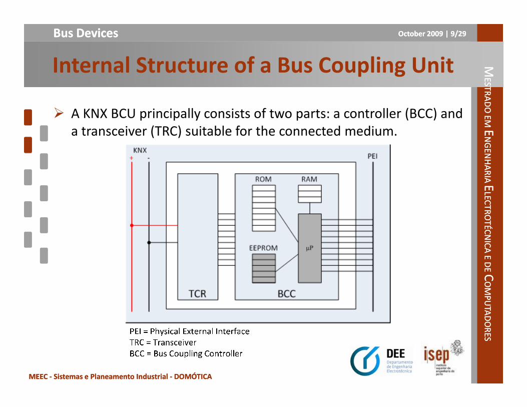
� A KNX BCU principally consists of two parts: a controller (BCC) and a transceiver (TRC) suitable for the connected medium.
LECTR
OTÉC
NIC
A E D
E LEC
TRO
TÉCN
ICA
E DE CC
OM
PU
TAD
OR
ESO
MP
UTA
DO
RES
MEEC MEEC -- Sistemas e Planeamento Industrial Sistemas e Planeamento Industrial -- DOMÓTICADOMÓTICA

OctoberOctober 2009 | 2009 | 1010/29/29Bus DevicesBus DevicesMM
ESTRA
DO
EM
ESTRA
DO
EM EE
NG
ENH
AR
IA
NG
ENH
AR
IA EE
LECTR
OTÉC
NIC
A E D
E LEC
TRO
TÉCN
ICA
E DE
Internal Structure of a Bus Coupling Unit
� In the different types of a memory of the microprocessor (µP) inside the controller, the following data is stored:
a) The system software: stored in ROM memory, the different standardised KNX system software profiles are identified by their “mask version” or “device descriptor type”. The mask version
LECTR
OTÉC
NIC
A E D
E LEC
TRO
TÉCN
ICA
E DE CC
OM
PU
TAD
OR
ESO
MP
UTA
DO
RES
MEEC MEEC -- Sistemas e Planeamento Industrial Sistemas e Planeamento Industrial -- DOMÓTICADOMÓTICA
“mask version” or “device descriptor type”. The mask version consists of 2 bytes where:
� the first digit y refers to the corresponding medium:0 for TP1, 1 for PL 110, 2 for RF and 5 for KNXnet/IP.
All software profiles not always contain the previously mentioned media.
� The last digit x refers to the current version of the software profile. ETS is informed about the mentioned system profiles by the next mask versions:

OctoberOctober 2009 | 2009 | 1111/29/29Bus DevicesBus DevicesMM
ESTRA
DO
EM
ESTRA
DO
EM EE
NG
ENH
AR
IA
NG
ENH
AR
IA EE
LECTR
OTÉC
NIC
A E D
E LEC
TRO
TÉCN
ICA
E DE
Internal Structure of a Bus Coupling Unit
Mask Versions• y01xh: System 12
• y02xh: System 23
• y70xh: System 74
• y7Bxh: System B
• y300h: LTE
• 091xh: TP1 Line/area coupler - Repeater
LECTR
OTÉC
NIC
A E D
E LEC
TRO
TÉCN
ICA
E DE CC
OM
PU
TAD
OR
ESO
MP
UTA
DO
RES
MEEC MEEC -- Sistemas e Planeamento Industrial Sistemas e Planeamento Industrial -- DOMÓTICADOMÓTICA
• 091xh: TP1 Line/area coupler - Repeater
• 190xh: Media coupler TP1-PL 110
• 2010h: RF bi-directional devices
• 2110h: RF unidirectional devices
Devices based on the latter two system profiles can for the time being not be handled by ETS. The system software is usually stored in ROM or Flash memory and can mostly not be overwritten.
2 Previously referred to as BCU13 Previously referred to as BCU24 Previously referred to as BIM M 112

OctoberOctober 2009 | 2009 | 1212/29/29Bus DevicesBus DevicesMM
ESTRA
DO
EM
ESTRA
DO
EM EE
NG
ENH
AR
IA
NG
ENH
AR
IA EE
LECTR
OTÉC
NIC
A E D
E LEC
TRO
TÉCN
ICA
E DE
Internal Structure of a Bus Coupling Unit
b) Temporary values of the system and the application: these are usually stored in RAM memory and lost (if not stored to EEPROM or Flash memory before power loss);
c) The application program, the individual and group addresses: these are usually stored in EEPROM or Flash memory and can be overwritten.
LECTR
OTÉC
NIC
A E D
E LEC
TRO
TÉCN
ICA
E DE CC
OM
PU
TAD
OR
ESO
MP
UTA
DO
RES
MEEC MEEC -- Sistemas e Planeamento Industrial Sistemas e Planeamento Industrial -- DOMÓTICADOMÓTICA
� The manufacturer makes the application program available to the installer as an ETS database, who then loads it into the device
� The manufacturer's code for the application program and the bus coupling unit must be identical to be able to load the application program.

OctoberOctober 2009 | 2009 | 1313/29/29Bus DevicesBus DevicesMM
ESTRA
DO
EM
ESTRA
DO
EM EE
NG
ENH
AR
IA
NG
ENH
AR
IA EE
LECTR
OTÉC
NIC
A E D
E LEC
TRO
TÉCN
ICA
E DE
Internal Structure of a Bus Coupling Unit
� The TP1 transceiver has the following functions:
� Separation or superimposing of the direct current and data;
� Reverse voltage protection (RPP);
� Generation of stabilized voltages of 5 respectively 24V;
� Initialing a data back-up if the bus village drops below 18V;
� Triggering a processor reset if the voltage drops below 4.5V;
LECTR
OTÉC
NIC
A E D
E LEC
TRO
TÉCN
ICA
E DE CC
OM
PU
TAD
OR
ESO
MP
UTA
DO
RES
MEEC MEEC -- Sistemas e Planeamento Industrial Sistemas e Planeamento Industrial -- DOMÓTICADOMÓTICA
� Driver for transmitting and receiving;
� Sending and receiving logic.

OctoberOctober 2009 | 2009 | 1414/29/29Bus DevicesBus DevicesMM
ESTRA
DO
EM
ESTRA
DO
EM EE
NG
ENH
AR
IA
NG
ENH
AR
IA EE
LECTR
OTÉC
NIC
A E D
E LEC
TRO
TÉCN
ICA
E DE
Type Definition of an Application Module
� Via a resistor (R- Type) in the application module, the bus coupling unit is able to detect via pin 6 of the PEI, whether the application module mounted on the BCU fits to the loaded application program.
LECTR
OTÉC
NIC
A E D
E LEC
TRO
TÉCN
ICA
E DE CC
OM
PU
TAD
OR
ESO
MP
UTA
DO
RES
MEEC MEEC -- Sistemas e Planeamento Industrial Sistemas e Planeamento Industrial -- DOMÓTICADOMÓTICA
program.
� When the R-Type does not correspond to the one indicated in the application program, the BCU automatically halts the application program

OctoberOctober 2009 | 2009 | 1515/29/29Bus DevicesBus DevicesMM
ESTRA
DO
EM
ESTRA
DO
EM EE
NG
ENH
AR
IA
NG
ENH
AR
IA EE
LECTR
OTÉC
NIC
A E D
E LEC
TRO
TÉCN
ICA
E DE
Type Definition of an Application Module
� The table below gives an overview of the principal PEI types.
LECTR
OTÉC
NIC
A E D
E LEC
TRO
TÉCN
ICA
E DE CC
OM
PU
TAD
OR
ESO
MP
UTA
DO
RES
MEEC MEEC -- Sistemas e Planeamento Industrial Sistemas e Planeamento Industrial -- DOMÓTICADOMÓTICA

OctoberOctober 2009 | 2009 | 1616/29/29Bus DevicesBus DevicesMM
ESTRA
DO
EM
ESTRA
DO
EM EE
NG
ENH
AR
IA
NG
ENH
AR
IA EE
LECTR
OTÉC
NIC
A E D
E LEC
TRO
TÉCN
ICA
E DE
Principal KNX Standardised System Profiles
System 1 (TP1/PL 110) - TP1 System 2 - TP1 System 7
� System 1 technology is the first generation of KNX devices. Products based on System 1 and System 7, have also been available on the market for some time. The table below gives an overview of the principal characteristics of these KNX system components:
LECTR
OTÉC
NIC
A E D
E LEC
TRO
TÉCN
ICA
E DE CC
OM
PU
TAD
OR
ESO
MP
UTA
DO
RES
MEEC MEEC -- Sistemas e Planeamento Industrial Sistemas e Planeamento Industrial -- DOMÓTICADOMÓTICA
� The System 7 technology is especially intended for more complex bus devices, which assume centralized functions (e.g. application controllers, gateways ... ).
� Application programs designed for System 1 technology can also be loaded into a System 2.
5 Previously referred to as “communication objects”

OctoberOctober 2009 | 2009 | 1717/29/29Bus DevicesBus DevicesMM
ESTRA
DO
EM
ESTRA
DO
EM EE
NG
ENH
AR
IA
NG
ENH
AR
IA EE
LECTR
OTÉC
NIC
A E D
E LEC
TRO
TÉCN
ICA
E DE
Principal KNX Standardised System Profiles
System 2 and System 7 Characteristics
� Access Control
When a tool wants to access memory of System 2 and 7 devices (reading and/or writing), it must first get authorization by means of an authorization key of 4 Byte.
LECTR
OTÉC
NIC
A E D
E LEC
TRO
TÉCN
ICA
E DE CC
OM
PU
TAD
OR
ESO
MP
UTA
DO
RES
MEEC MEEC -- Sistemas e Planeamento Industrial Sistemas e Planeamento Industrial -- DOMÓTICADOMÓTICA
authorization key of 4 Byte.
A manufacturer can define up to 16 such keys for a System 7 product or 4 keys for a System 2 product: however some of these are reserved for access to system relevant memory (amongst others the highest access key 0) and are therefore not communicated to the customers. The ETS (from version 1.1 onwards) is able to address these access mechanisms of the above mentioned device types.
Access control is never needed for normal communication via group addresses. In this case access is always possible

OctoberOctober 2009 | 2009 | 1818/29/29Bus DevicesBus DevicesMM
ESTRA
DO
EM
ESTRA
DO
EM EE
NG
ENH
AR
IA
NG
ENH
AR
IA EE
LECTR
OTÉC
NIC
A E D
E LEC
TRO
TÉCN
ICA
E DE
Principal KNX Standardised System Profiles
System 2 and System 7 Characteristics
� Serial number
System 2 and System 7 devices use a serial number: this number, which is assigned to each device before leaving the factory, allows writing or reading the individual address (physical address) of a device without having to press the programming button of the device. This feature is however not yet supported in
LECTR
OTÉC
NIC
A E D
E LEC
TRO
TÉCN
ICA
E DE CC
OM
PU
TAD
OR
ESO
MP
UTA
DO
RES
MEEC MEEC -- Sistemas e Planeamento Industrial Sistemas e Planeamento Industrial -- DOMÓTICADOMÓTICA
programming button of the device. This feature is however not yet supported in ETS.
� Interface Objects
Interface Objects contain certain system and application properties (e.g. address table, parameters ... ), which can be read and/or written by a tool (e.g. ETS during download).

OctoberOctober 2009 | 2009 | 1919/29/29Bus DevicesBus DevicesMM
ESTRA
DO
EM
ESTRA
DO
EM EE
NG
ENH
AR
IA
NG
ENH
AR
IA EE
LECTR
OTÉC
NIC
A E D
E LEC
TRO
TÉCN
ICA
E DE
Dimming With Start/Stop Telegram
� The duration of the key operation determines whether the switching function or the dimming function is activated.
� If the time the key is pressed is shorter than t2 (e.g. <500 ms), a switch telegram is transmitted.
LECTR
OTÉC
NIC
A E D
E LEC
TRO
TÉCN
ICA
E DE CC
OM
PU
TAD
OR
ESO
MP
UTA
DO
RES
MEEC MEEC -- Sistemas e Planeamento Industrial Sistemas e Planeamento Industrial -- DOMÓTICADOMÓTICA
� Longer periods of key operation after the period t2 cause the transmission of a “start dimming” telegram. As soon as the key is released again, a “stop dimming” telegram is transmitted. The time t1 is used for key debouncing.
� Different group addresses are used for the switching and dimming telegrams to ensure that the dimming actuator executes the correct functions.

OctoberOctober 2009 | 2009 | 2020/29/29Bus DevicesBus DevicesMM
ESTRA
DO
EM
ESTRA
DO
EM EE
NG
ENH
AR
IA
NG
ENH
AR
IA EE
LECTR
OTÉC
NIC
A E D
E LEC
TRO
TÉCN
ICA
E DE
Dimming With Start/Stop Telegram
LECTR
OTÉC
NIC
A E D
E LEC
TRO
TÉCN
ICA
E DE CC
OM
PU
TAD
OR
ESO
MP
UTA
DO
RES
MEEC MEEC -- Sistemas e Planeamento Industrial Sistemas e Planeamento Industrial -- DOMÓTICADOMÓTICA

OctoberOctober 2009 | 2009 | 2121/29/29Bus DevicesBus DevicesMM
ESTRA
DO
EM
ESTRA
DO
EM EE
NG
ENH
AR
IA
NG
ENH
AR
IA EE
LECTR
OTÉC
NIC
A E D
E LEC
TRO
TÉCN
ICA
E DE
Dimming With Cyclical Telegrams
� In a system controlled by infrared light, the light beam might be interrupted as somebody passes by.
� In order to avoid a situation where the dimming actuator does not receive telegrams (e.g. the stop telegram), in most cases one will choose the setting “cyclical dimming” during
LECTR
OTÉC
NIC
A E D
E LEC
TRO
TÉCN
ICA
E DE CC
OM
PU
TAD
OR
ESO
MP
UTA
DO
RES
MEEC MEEC -- Sistemas e Planeamento Industrial Sistemas e Planeamento Industrial -- DOMÓTICADOMÓTICA
will choose the setting “cyclical dimming” during parameterization of an infrared control.
� The infrared sensor in these settings transmits the telegram “increase brightness by 12.5%”.
� The consequences of losing such a telegram are not as serious as the loss of a stop telegram, which is only sent once.

OctoberOctober 2009 | 2009 | 2222/29/29Bus DevicesBus DevicesMM
ESTRA
DO
EM
ESTRA
DO
EM EE
NG
ENH
AR
IA
NG
ENH
AR
IA EE
LECTR
OTÉC
NIC
A E D
E LEC
TRO
TÉCN
ICA
E DE
Dimming With Cyclical Telegrams
LECTR
OTÉC
NIC
A E D
E LEC
TRO
TÉCN
ICA
E DE CC
OM
PU
TAD
OR
ESO
MP
UTA
DO
RES
MEEC MEEC -- Sistemas e Planeamento Industrial Sistemas e Planeamento Industrial -- DOMÓTICADOMÓTICA
OctoberOctober 2009 | 2009 | 2323/29/29Bus DevicesBus DevicesMM
ESTRA
DO
EM
ESTRA
DO
EM EE
NG
ENH
AR
IA
NG
ENH
AR
IA EE
LECTR
OTÉC
NIC
A E D
E LEC
TRO
TÉCN
ICA
E DE
Application Function: LF Dimming Actuator
� During the dimming period, the bus coupling unit increases or decreases the digital brightness value according to the set regulating time. The brightness value is continuously passed on to the shift register (SR) in the application unit.
� The 8 bit long data word allows the generation of 28 = 256 brightness values.
LECTR
OTÉC
NIC
A E D
E LEC
TRO
TÉCN
ICA
E DE CC
OM
PU
TAD
OR
ESO
MP
UTA
DO
RES
MEEC MEEC -- Sistemas e Planeamento Industrial Sistemas e Planeamento Industrial -- DOMÓTICADOMÓTICA
brightness values.
� The data word is fed into the digital/analogue converter (DAC), which then generates the appropriate control voltage in the range of 0 to 10V.
� The dimmer's electronic choke uses the voltage to control the light emission of a fluorescent tube. The power circuit breaker in the application unit is used to (dis)connect the mains voltage.

OctoberOctober 2009 | 2009 | 2424/29/29Bus DevicesBus DevicesMM
ESTRA
DO
EM
ESTRA
DO
EM EE
NG
ENH
AR
IA
NG
ENH
AR
IA EE
LECTR
OTÉC
NIC
A E D
E LEC
TRO
TÉCN
ICA
E DE
Application Function: LF Dimming Actuator
LECTR
OTÉC
NIC
A E D
E LEC
TRO
TÉCN
ICA
E DE CC
OM
PU
TAD
OR
ESO
MP
UTA
DO
RES
MEEC MEEC -- Sistemas e Planeamento Industrial Sistemas e Planeamento Industrial -- DOMÓTICADOMÓTICA

OctoberOctober 2009 | 2009 | 2525/29/29Bus DevicesBus DevicesMM
ESTRA
DO
EM
ESTRA
DO
EM EE
NG
ENH
AR
IA
NG
ENH
AR
IA EE
LECTR
OTÉC
NIC
A E D
E LEC
TRO
TÉCN
ICA
E DE
Application: Drive Control Sensor
� The time t2 (e.g. 500 ms) acts as a “boundary” between the commands “slats open/close 1 step” and “blinds up/down”.
LECTR
OTÉC
NIC
A E D
E LEC
TRO
TÉCN
ICA
E DE CC
OM
PU
TAD
OR
ESO
MP
UTA
DO
RES
MEEC MEEC -- Sistemas e Planeamento Industrial Sistemas e Planeamento Industrial -- DOMÓTICADOMÓTICA

OctoberOctober 2009 | 2009 | 2626/29/29Bus DevicesBus DevicesMM
ESTRA
DO
EM
ESTRA
DO
EM EE
NG
ENH
AR
IA
NG
ENH
AR
IA EE
LECTR
OTÉC
NIC
A E D
E LEC
TRO
TÉCN
ICA
E DE
Application: Drive Control
� Depending on the telegram received, the BCU transmits the command “up” or the command “down” to the power circuit breaker S2.
� On receiving the telegrams “slats open/close 1 step”, the BCU energizes the circuit breaker S1 for the appropriate duration. LEC
TRO
TÉCN
ICA
E DE
LECTR
OTÉC
NIC
A E D
E CCO
MP
UTA
DO
RES
OM
PU
TAD
OR
ES
MEEC MEEC -- Sistemas e Planeamento Industrial Sistemas e Planeamento Industrial -- DOMÓTICADOMÓTICA
� If the motor was already switched on, this telegram halts the blind.
� On receiving the telegram “blinds up/down”, the BCU energizes the circuit breaker S1 for a period longer than the time the blind is in movement.
� As usual the limit switches bring the motor to a halt when one of the limit positions is reached.

OctoberOctober 2009 | 2009 | 2727/29/29Bus DevicesBus DevicesMM
ESTRA
DO
EM
ESTRA
DO
EM EE
NG
ENH
AR
IA
NG
ENH
AR
IA EE
LECTR
OTÉC
NIC
A E D
E LEC
TRO
TÉCN
ICA
E DE
Application: Drive Control
LECTR
OTÉC
NIC
A E D
E LEC
TRO
TÉCN
ICA
E DE CC
OM
PU
TAD
OR
ESO
MP
UTA
DO
RES
MEEC MEEC -- Sistemas e Planeamento Industrial Sistemas e Planeamento Industrial -- DOMÓTICADOMÓTICA

OctoberOctober 2009 | 2009 | 2828/29/29Bus DevicesBus DevicesMM
ESTRA
DO
EM
ESTRA
DO
EM EE
NG
ENH
AR
IA
NG
ENH
AR
IA EE
LECTR
OTÉC
NIC
A E D
E LEC
TRO
TÉCN
ICA
E DE
Drive Control Object Structure
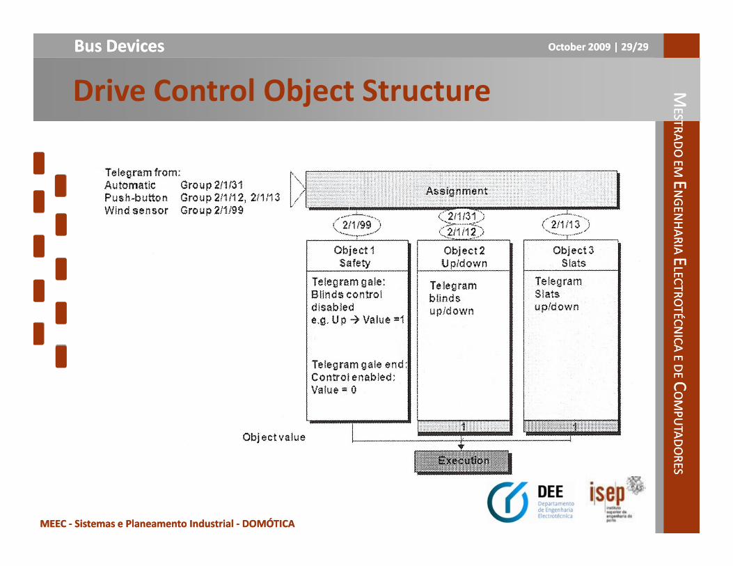
� If, for example, the sensor responsible for measuring the position of the sun triggers the telegram “blinds down” using the group address 2/31, the object group "up/down" is addressed and the corresponding command is executed.
� Brief operation of the key sensor transmits the 2/13 telegram “adjust slats” and long operation of the key sensor sends the 2/12 telegram
LECTR
OTÉC
NIC
A E D
E LEC
TRO
TÉCN
ICA
E DE CC
OM
PU
TAD
OR
ESO
MP
UTA
DO
RES
MEEC MEEC -- Sistemas e Planeamento Industrial Sistemas e Planeamento Industrial -- DOMÓTICADOMÓTICA
slats” and long operation of the key sensor sends the 2/12 telegram “open/close blinds completely”.
� Telegram 2/99 triggered by the wind sensor addresses the object group “security”.
� If a gale is developing, telegram 2/99 orders the blinds to be opened completely and disables any further operations.
� When the storm has eased off, a telegram is sent that enables blind operation again.
OctoberOctober 2009 | 2009 | 2929/29/29Bus DevicesBus DevicesMM
ESTRA
DO
EM
ESTRA
DO
EM EE
NG
ENH
AR
IA
NG
ENH
AR
IA EE
LECTR
OTÉC
NIC
A E D
E LEC
TRO
TÉCN
ICA
E DE
Drive Control Object Structure
LECTR
OTÉC
NIC
A E D
E LEC
TRO
TÉCN
ICA
E DE CC
OM
PU
TAD
OR
ESO
MP
UTA
DO
RES
MEEC MEEC -- Sistemas e Planeamento Industrial Sistemas e Planeamento Industrial -- DOMÓTICADOMÓTICA