Embed Size (px)
Citation preview
900MonteringsanvisningSCdefault
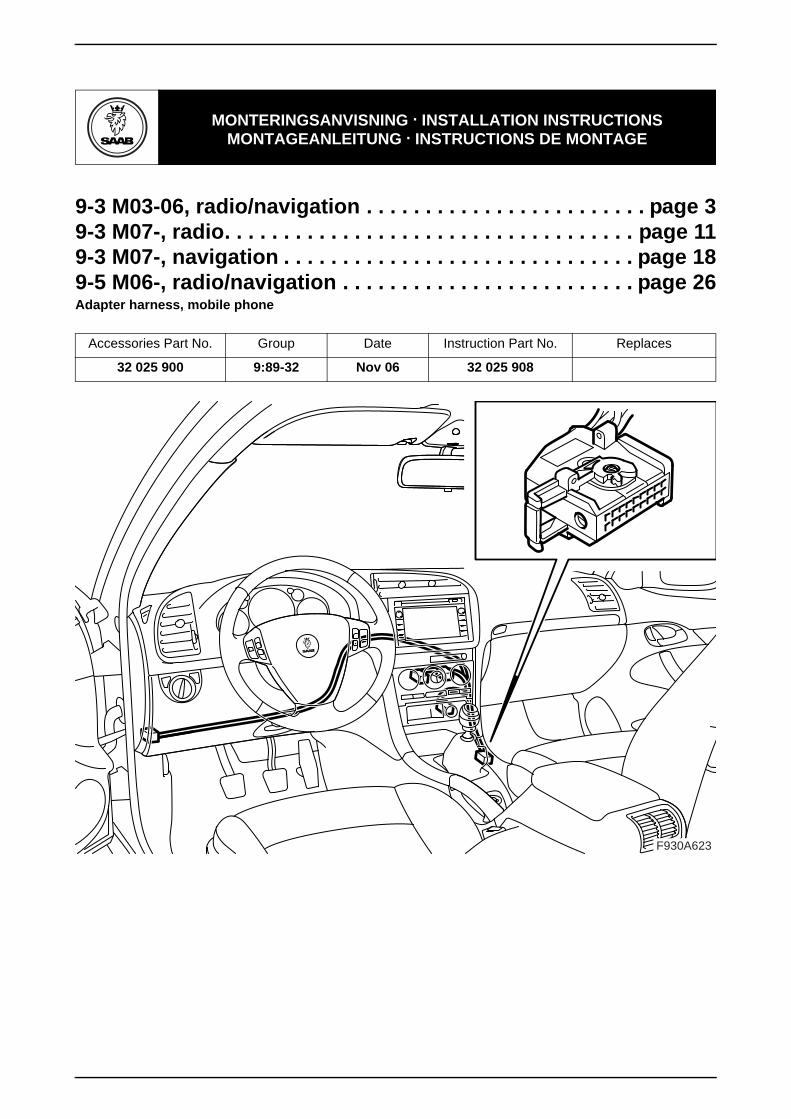
MONTERINGSANVISNING · INSTALLATION INSTRUCTIONS MONTAGEANLEITUNG · INSTRUCTIONS DE MONTAGE
SITdefault
9-3 M03-06, radio/navigation . . . . . . . . . . . . . . . . . . . . . . . . page 39-3 M07-, radio. . . . . . . . . . . . . . . . . . . . . . . . . . . . . . . . . . . page 119-3 M07-, navigation . . . . . . . . . . . . . . . . . . . . . . . . . . . . . . page 189-5 M06-, radio/navigation . . . . . . . . . . . . . . . . . . . . . . . . . page 26Adapter harness, mobile phone
Accessories Part No. Group Date Instruction Part No. Replaces
32 025 900 9:89-32 Nov 06 32 025 908
F930A623
2 32 025 908
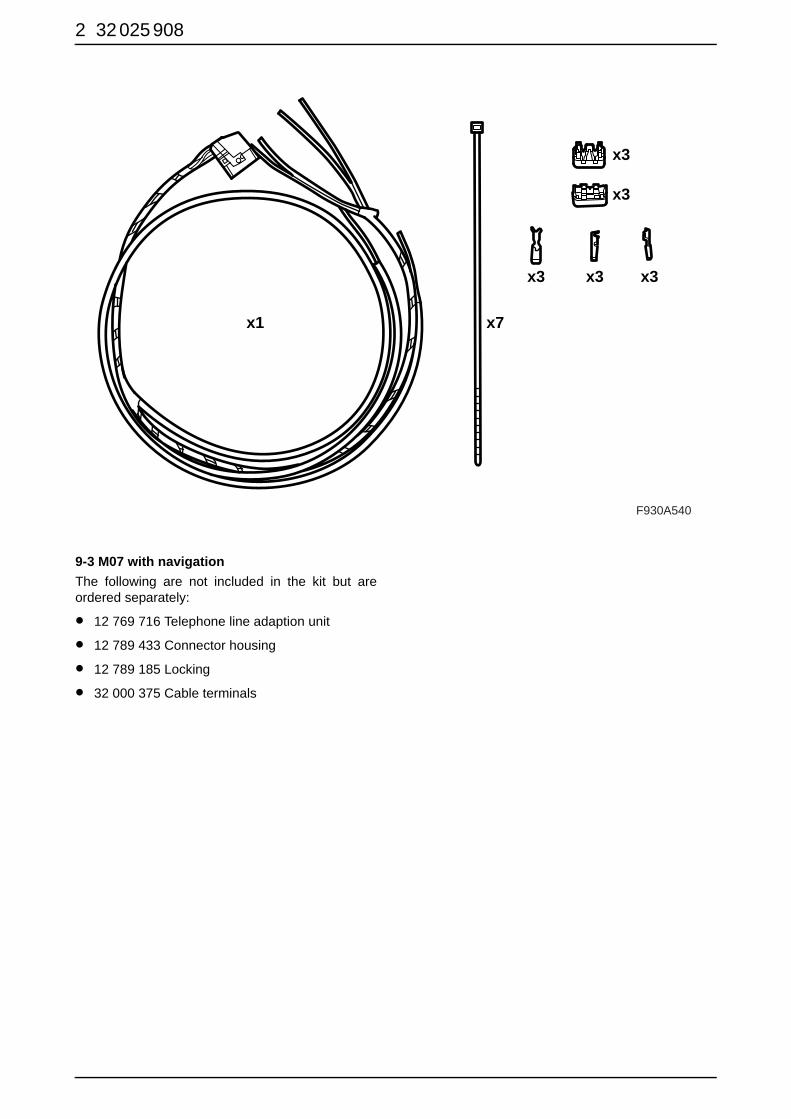
9-3 M07 with navigationThe following are not included in the kit but areordered separately:
• 12 769 716 Telephone line adaption unit
• 12 789 433 Connector housing
• 12 789 185 Locking
• 32 000 375 Cable terminals
F930A540
x1 x7
x3
x3
x3
x3 x3
32 025 908 3
9-3 M03-06, radio/navigation
9-3 M03-06, radio/navigation
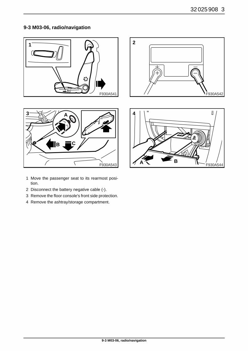
1 Move the passenger seat to its rearmost posi-tion.
2 Disconnect the battery negative cable (-).3 Remove the floor console's front side protection.4 Remove the ashtray/storage compartment.
F930A543
3
B C
A
F930A541
1
F930A542
2
F930A544A B
4
4 32 025 908
9-3 M03-06, radio/navigation
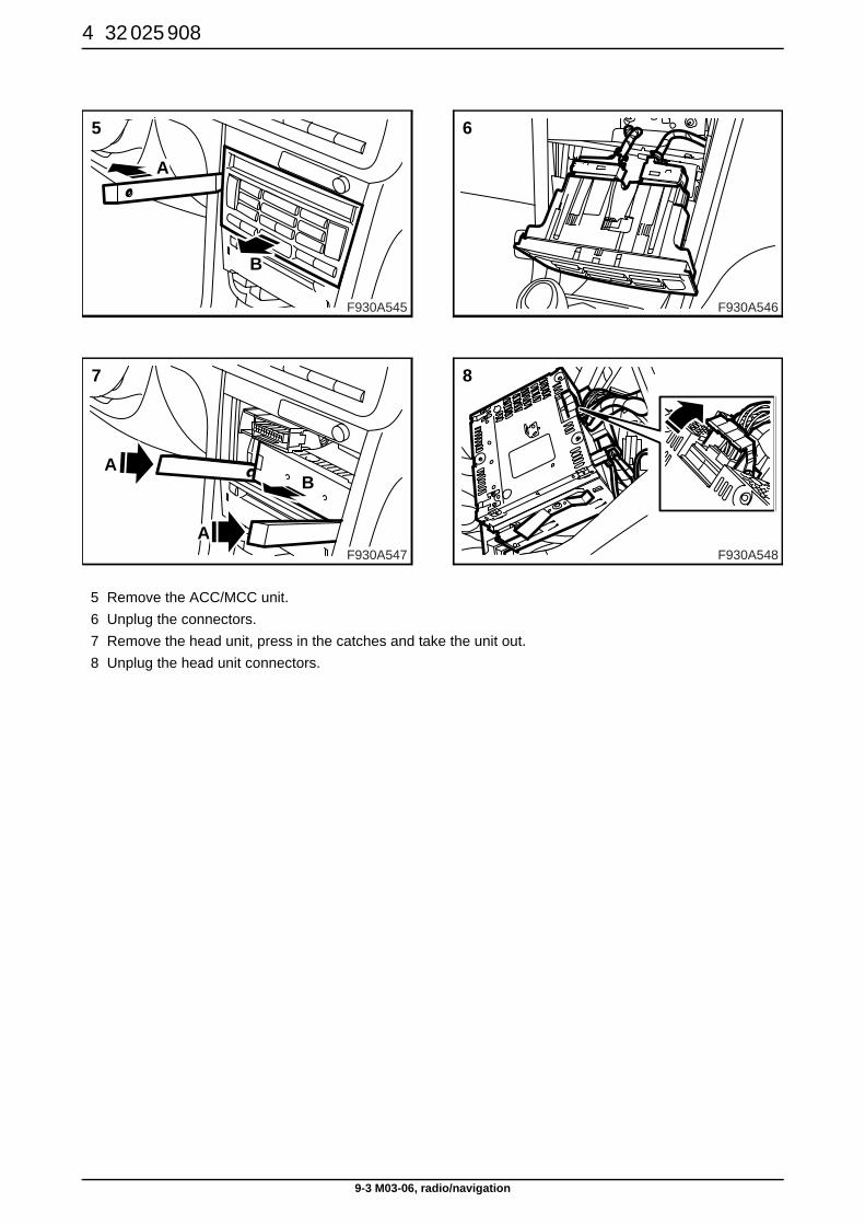
5 Remove the ACC/MCC unit. 6 Unplug the connectors.7 Remove the head unit, press in the catches and take the unit out.8 Unplug the head unit connectors.
F930A547
7
A
A
B
F930A545
5
A
B
F930A546
6
F930A548
8
32 025 908 5
9-3 M03-06, radio/navigation
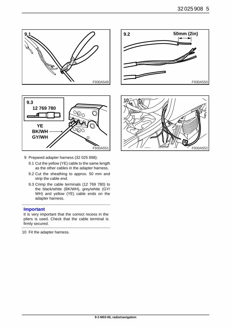
9 Prepared adapter harness (32 025 898): 9.1 Cut the yellow (YE) cable to the same length
as the other cables in the adapter harness.9.2 Cut the sheathing to approx. 50 mm and
strip the cable end.9.3 Crimp the cable terminals (12 769 780) to
the black/white (BK/WH), grey/white (GY/WH) and yellow (YE) cable ends on theadapter harness.
10 Fit the adapter harness.
ImportantIt is very important that the correct recess in thepliers is used. Check that the cable terminal isfirmly secured.
F930A551
12 769 780
YEBK/WHGY/WH
9.3
F930A549
9.1
F930A550
9.2 50mm (2in)
F930A552
10
6 32 025 908
9-3 M03-06, radio/navigation
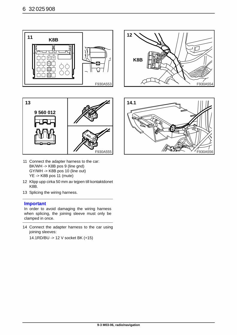
11 Connect the adapter harness to the car: BK/WH -> K8B pos 9 (line gnd)GY/WH -> K8B pos 10 (line out)YE -> K8B pos 11 (mute)
12 Klipp upp cirka 50 mm av tejpen till kontaktdonetK8B.
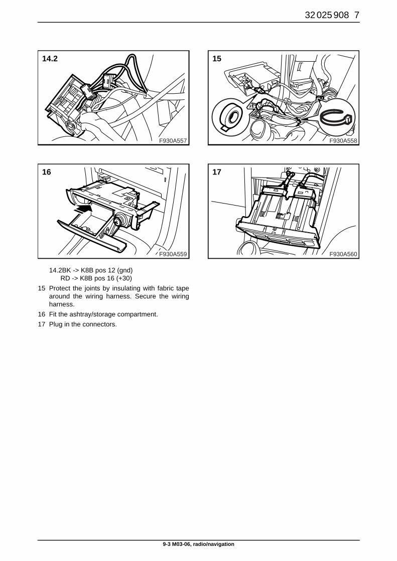
13 Splicing the wiring harness.
14 Connect the adapter harness to the car usingjoining sleeves:14.1RD/BU -> 12 V socket BK (+15)
ImportantIn order to avoid damaging the wiring harnesswhen splicing, the joining sleeve must only beclamped in once.
F930A555
13
9 560 012
YE
BK RD
GY
BKWH
WH
4
3
8
7
12
11
16
15
2
1
6
5
10
9
14
13
3
4
1
2
F930A553
11 K8B
F930A554
12
K8B
F930A556
14.1
32 025 908 7
9-3 M03-06, radio/navigation
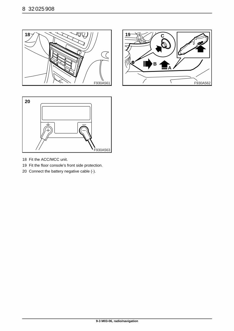
14.2BK -> K8B pos 12 (gnd)RD -> K8B pos 16 (+30)
15 Protect the joints by insulating with fabric tapearound the wiring harness. Secure the wiringharness.
16 Fit the ashtray/storage compartment.17 Plug in the connectors.
F930A559
16
F930A557
14.2
F930A558
15
F930A560
17
8 32 025 908
9-3 M03-06, radio/navigation
18 Fit the ACC/MCC unit. 19 Fit the floor console's front side protection.20 Connect the battery negative cable (-).
F930A563
20
F930A561
18
F930A562
BA
C19
32 025 908 9
9-3 M03-06, radio/navigation
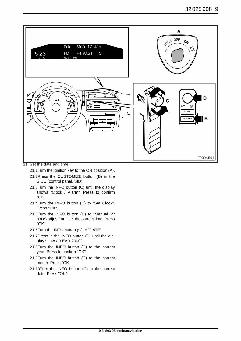
21 Set the date and time: 21.1Turn the ignition key to the ON position (A).21.2Press the CUSTOMIZE button (B) in the
SIDC (control panel, SID).21.3Turn the INFO button (C) until the display
shows “Clock / Alarm”. Press to confirm"OK".
21.4Turn the INFO button (C) to “Set Clock”.Press "OK".
21.5Turn the INFO button (C) to “Manual” or"RDS adjust" and set the correct time. Press"OK".
21.6Turn the INFO button (C) to "DATE".21.7Press in the INFO button (D) until the dis-
play shows "YEAR 2000".21.8Turn the INFO button (C) to the correct
year. Press to confirm "OK".21.9Turn the INFO button (C) to the correct
month. Press "OK".21.10Turn the INFO button (C) to the correct
date. Press "OK".
F930A564
A
B
C D
10 32 025 908
9-3 M03-06, radio/navigation
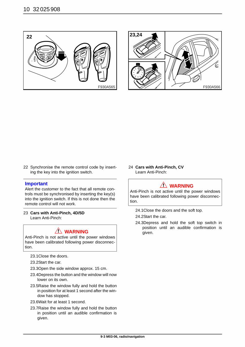
22 Synchronise the remote control code by insert-ing the key into the ignition switch.
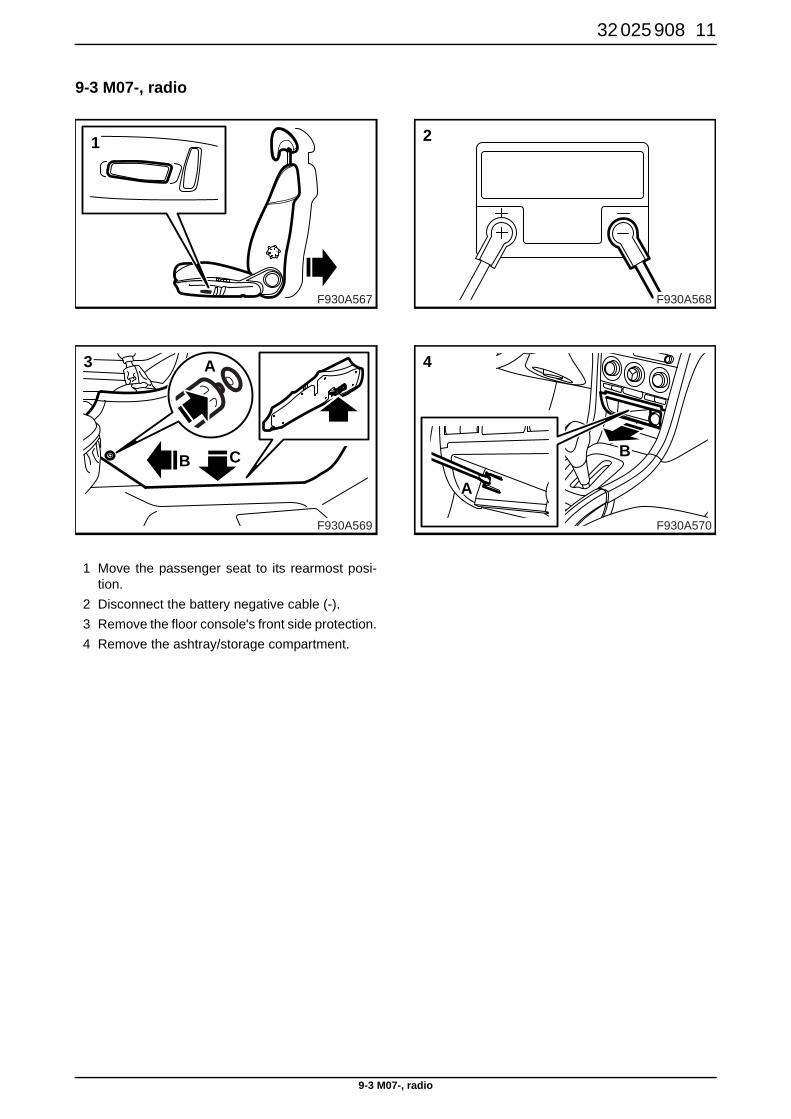
23 Cars with Anti-Pinch, 4D/5D Learn Anti-Pinch:
23.1Close the doors. 23.2Start the car.23.3Open the side window approx. 15 cm.23.4Depress the button and the window will now
lower on its own. 23.5Raise the window fully and hold the button
in position for at least 1 second after the win-dow has stopped.
23.6Wait for at least 1 second.23.7Raise the window fully and hold the button
in position until an audible confirmation isgiven.
24 Cars with Anti-Pinch, CV Learn Anti-Pinch:
24.1Close the doors and the soft top.24.2Start the car.24.3Depress and hold the soft top switch in
position until an audible confirmation isgiven.
ImportantAlert the customer to the fact that all remote con-trols must be synchronised by inserting the key(s)into the ignition switch. If this is not done then theremote control will not work.
WARNINGAnti-Pinch is not active until the power windowshave been calibrated following power disconnec-tion.
F930A565
22
F930A566
23,24
WARNINGAnti-Pinch is not active until the power windowshave been calibrated following power disconnec-tion.
32 025 908 11
9-3 M07-, radio
9-3 M07-, radio
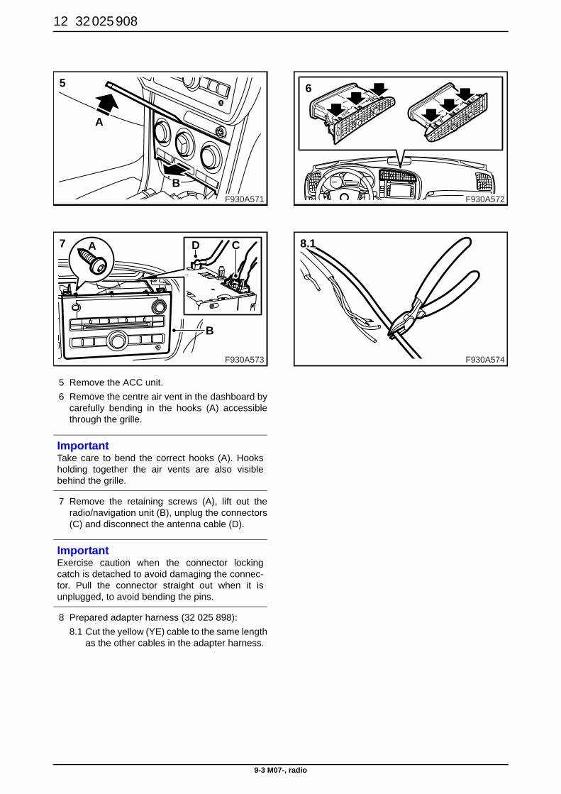
1 Move the passenger seat to its rearmost posi-tion.
2 Disconnect the battery negative cable (-).3 Remove the floor console's front side protection.4 Remove the ashtray/storage compartment.
F930A569
3
B C
A
F930A567
1
F930A568
2
F930A570
4
A
B
12 32 025 908
9-3 M07-, radio
5 Remove the ACC unit. 6 Remove the centre air vent in the dashboard by
carefully bending in the hooks (A) accessiblethrough the grille.
7 Remove the retaining screws (A), lift out theradio/navigation unit (B), unplug the connectors(C) and disconnect the antenna cable (D).
8 Prepared adapter harness (32 025 898): 8.1 Cut the yellow (YE) cable to the same length
as the other cables in the adapter harness.
ImportantTake care to bend the correct hooks (A). Hooksholding together the air vents are also visiblebehind the grille.
ImportantExercise caution when the connector lockingcatch is detached to avoid damaging the connec-tor. Pull the connector straight out when it isunplugged, to avoid bending the pins.
F930A573
7 A
B
D C
F930A571
5
A
BF930A572
6
F930A574
8.1

32 025 908 13
9-3 M07-, radio
8.2 Cut the sheathing to approx. 50 mm andstrip the cable end.
8.3 Crimp the cable terminals (12 769 135) tothe black/white (BK/WH), grey/white (GY/WH) and yellow (YE) cable ends on theadapter harness.
9 Connector, overview.10 Connect the adapter harness to the car:
10.1BK/WH -> K14 pos 5 (line gnd)10.2GY/WH -> K14 pos 4 (line out)10.3YE -> K16 pos 4 (mute)
ImportantIt is very important that the correct recess in thepliers is used. Check that the cable terminal isfirmly secured.
BK
BK
RD
WHGYWH
3 2
9101112
45
1
8
6
13
7
14
1
9
2
1016
8
15
7 6 5
14 13
4
12
3
11
YE
F930A578
9K14 K16
F930A575
8.2 50mm (2in)
F930A576
12 769 135
YEBK/WHGY/WH
8.3
F930A582
10
14 32 025 908
9-3 M07-, radio
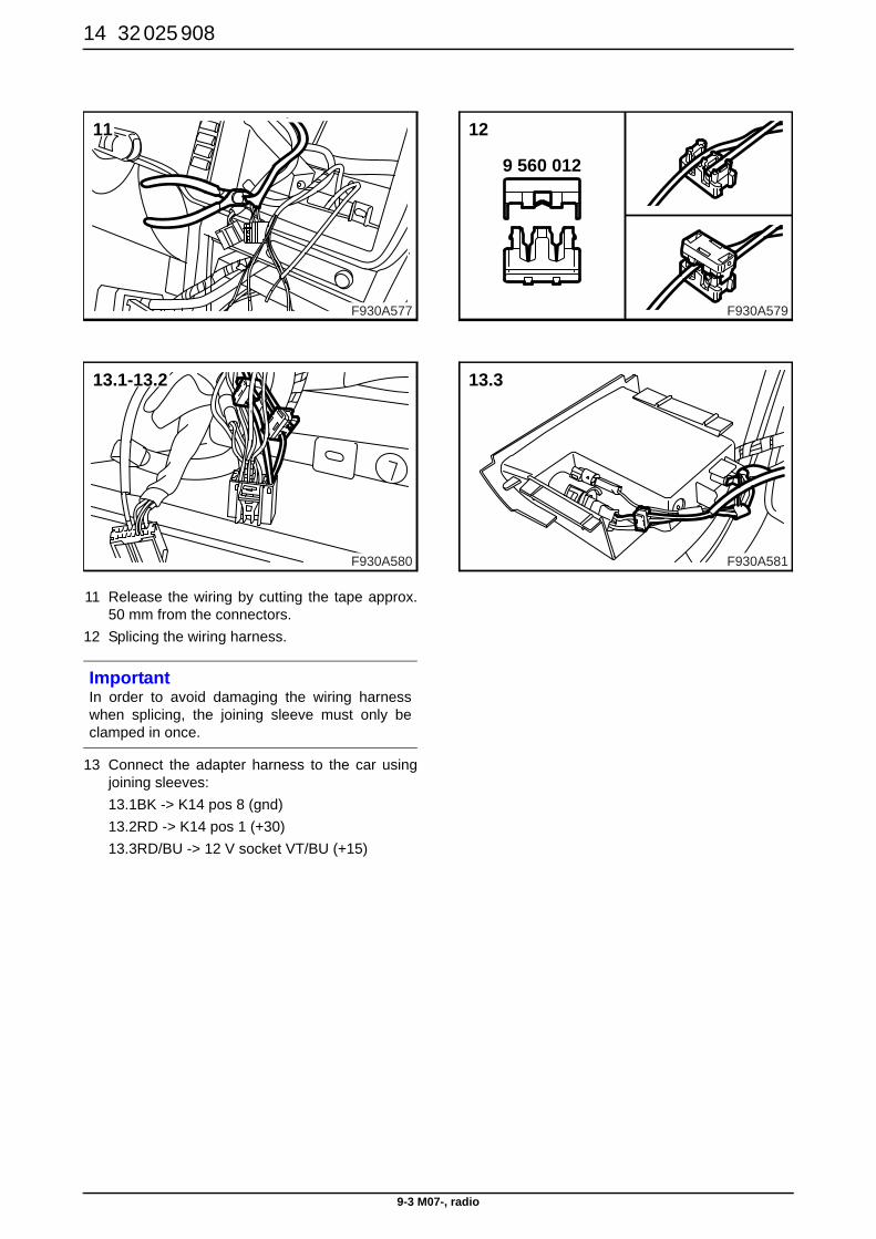
11 Release the wiring by cutting the tape approx.50 mm from the connectors.
12 Splicing the wiring harness.
13 Connect the adapter harness to the car usingjoining sleeves:13.1BK -> K14 pos 8 (gnd)13.2RD -> K14 pos 1 (+30)13.3RD/BU -> 12 V socket VT/BU (+15)
ImportantIn order to avoid damaging the wiring harnesswhen splicing, the joining sleeve must only beclamped in once.
F930A580
13.1-13.2
F930A577
11
F930A579
12
9 560 012
F930A581
13.3
32 025 908 15
9-3 M07-, radio
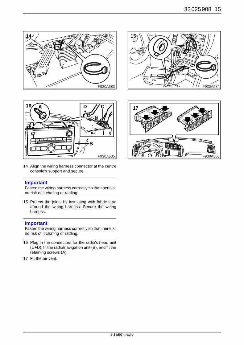
14 Align the wiring harness connector at the centreconsole's support and secure.
15 Protect the joints by insulating with fabric tapearound the wiring harness. Secure the wiringharness.
16 Plug in the connectors for the radio's head unit(C+D), fit the radio/navigation unit (B), and fit theretaining screws (A).
17 Fit the air vent.
ImportantFasten the wiring harness correctly so that there isno risk of it chafing or rattling.
ImportantFasten the wiring harness correctly so that there isno risk of it chafing or rattling.
F930A585
16 A
B
D C
F930A583
14
F930A584
15
F930A586
17
16 32 025 908
9-3 M07-, radio
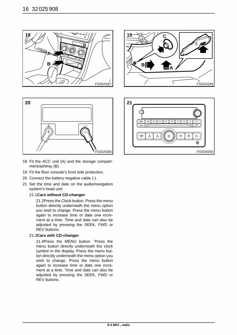
18 Fit the ACC unit (A) and the storage compart-ment/ashtray (B).
19 Fit the floor console's front side protection.20 Connect the battery negative cable (-).21 Set the time and date on the audio/navigation
system's head unit:21.1Cars without CD-changer:
21.2Press the Clock button. Press the menubutton directly underneath the menu optionyou wish to change. Press the menu buttonagain to increase time or date one incre-ment at a time. Time and date can also beadjusted by pressing the SEEK, FWD orREV buttons.
21.3Cars with CD-changer:21.4Press the MENU button. ‘Press themenu button directly underneath the clocksymbol in the display. Press the menu but-ton directly underneath the menu option youwish to change. Press the menu buttonagain to increase time or date one incre-ment at a time. Time and date can also beadjusted by pressing the SEEK, FWD orREV buttons.
F930A589
20
F930A587
18
B
A
F930A588
BA
C19
F930A590
21
32 025 908 17
9-3 M07-, radio
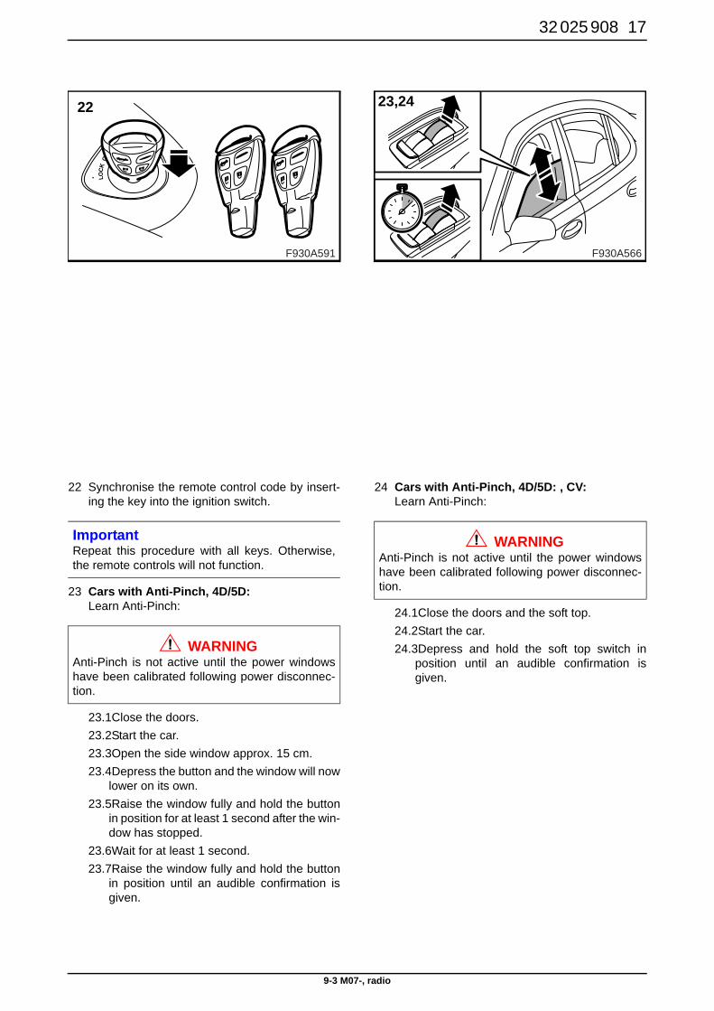
22 Synchronise the remote control code by insert-ing the key into the ignition switch.
23 Cars with Anti-Pinch, 4D/5D: Learn Anti-Pinch:
23.1Close the doors. 23.2Start the car.23.3Open the side window approx. 15 cm.23.4Depress the button and the window will now
lower on its own. 23.5Raise the window fully and hold the button
in position for at least 1 second after the win-dow has stopped.
23.6Wait for at least 1 second.23.7Raise the window fully and hold the button
in position until an audible confirmation isgiven.
24 Cars with Anti-Pinch, 4D/5D: , CV: Learn Anti-Pinch:
24.1Close the doors and the soft top.24.2Start the car.24.3Depress and hold the soft top switch in
position until an audible confirmation isgiven.
ImportantRepeat this procedure with all keys. Otherwise,the remote controls will not function.
WARNINGAnti-Pinch is not active until the power windowshave been calibrated following power disconnec-tion.
F930A591
22
F930A566
23,24
WARNINGAnti-Pinch is not active until the power windowshave been calibrated following power disconnec-tion.
18 32 025 908
9-3 M07-, navigation
9-3 M07-, navigation
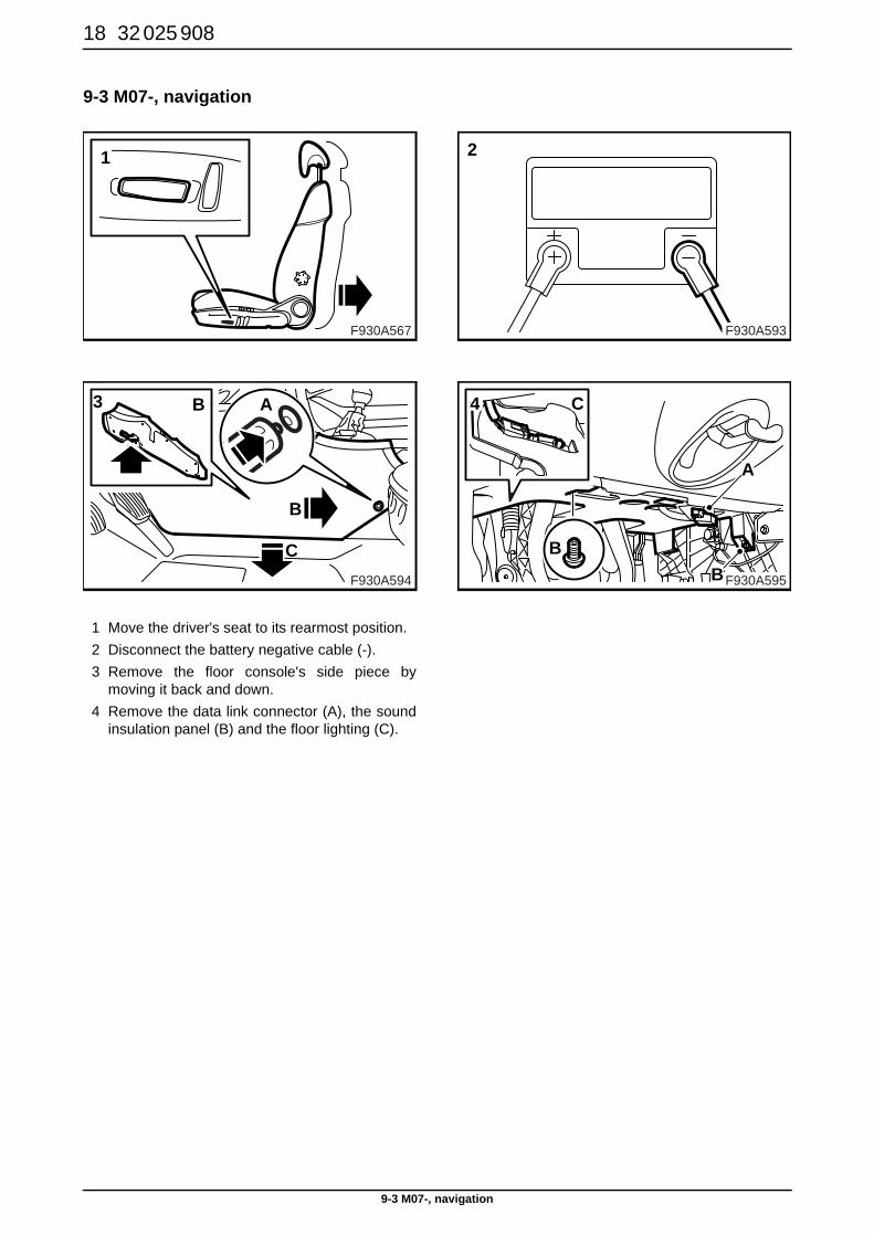
1 Move the driver's seat to its rearmost position. 2 Disconnect the battery negative cable (-).3 Remove the floor console's side piece by
moving it back and down.4 Remove the data link connector (A), the sound
insulation panel (B) and the floor lighting (C).
F930A594
B
B
C
A3
F930A567
1
F930A593
2
F930A595
B
4 C
A
B
32 025 908 19
9-3 M07-, navigation
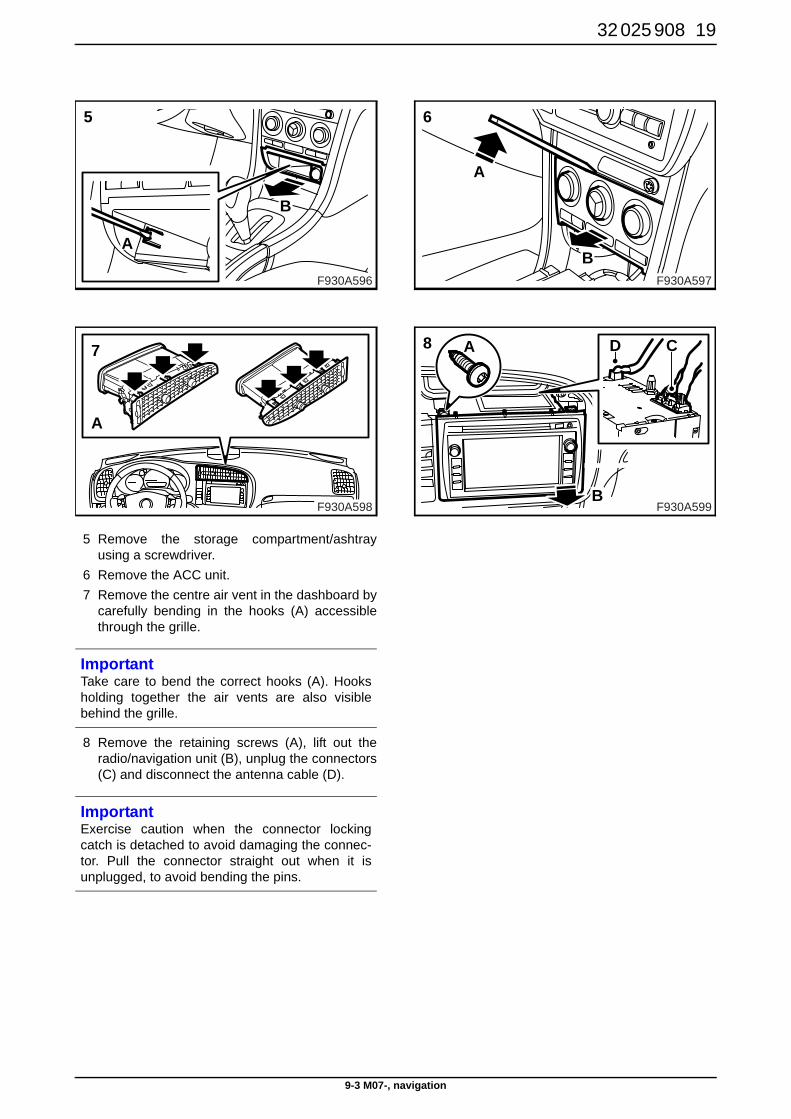
5 Remove the storage compartment/ashtrayusing a screwdriver.
6 Remove the ACC unit. 7 Remove the centre air vent in the dashboard by
carefully bending in the hooks (A) accessiblethrough the grille.
8 Remove the retaining screws (A), lift out theradio/navigation unit (B), unplug the connectors(C) and disconnect the antenna cable (D).
ImportantTake care to bend the correct hooks (A). Hooksholding together the air vents are also visiblebehind the grille.
ImportantExercise caution when the connector lockingcatch is detached to avoid damaging the connec-tor. Pull the connector straight out when it isunplugged, to avoid bending the pins.
F930A598
7
A
F930A596
5
A
B
F930A597
6
A
B
F930A599
8 A
B
D C
20 32 025 908
9-3 M07-, navigation
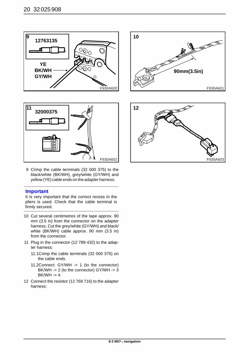
9 Crimp the cable terminals (32 000 375) to theblack/white (BK/WH), grey/white (GY/WH) andyellow (YE) cable ends on the adapter harness.
10 Cut several centimetres of the tape approx. 90mm (3.5 in) from the connector on the adapterharness. Cut the grey/white (GY/WH) and black/white (BK/WH) cable approx. 90 mm (3.5 in)from the connector.
11 Plug in the connector (12 789 432) to the adap-ter harness: 11.1Crimp the cable terminals (32 000 375) on
the cable ends. 11.2Connect: GY/WH -> 1 (to the connector)
BK/WH -> 2 (to the connector) GY/WH -> 3BK/WH -> 4.
12 Connect the resistor (12 769 716) to the adapterharness:
ImportantIt is very important that the correct recess in thepliers is used. Check that the cable terminal isfirmly secured.
11
F930A602
32000375
F930A600
12763135
YEBK/WHGY/WH
9
F930A601
10
90mm(3.5in)
F930A603
12
32 025 908 21
9-3 M07-, navigation
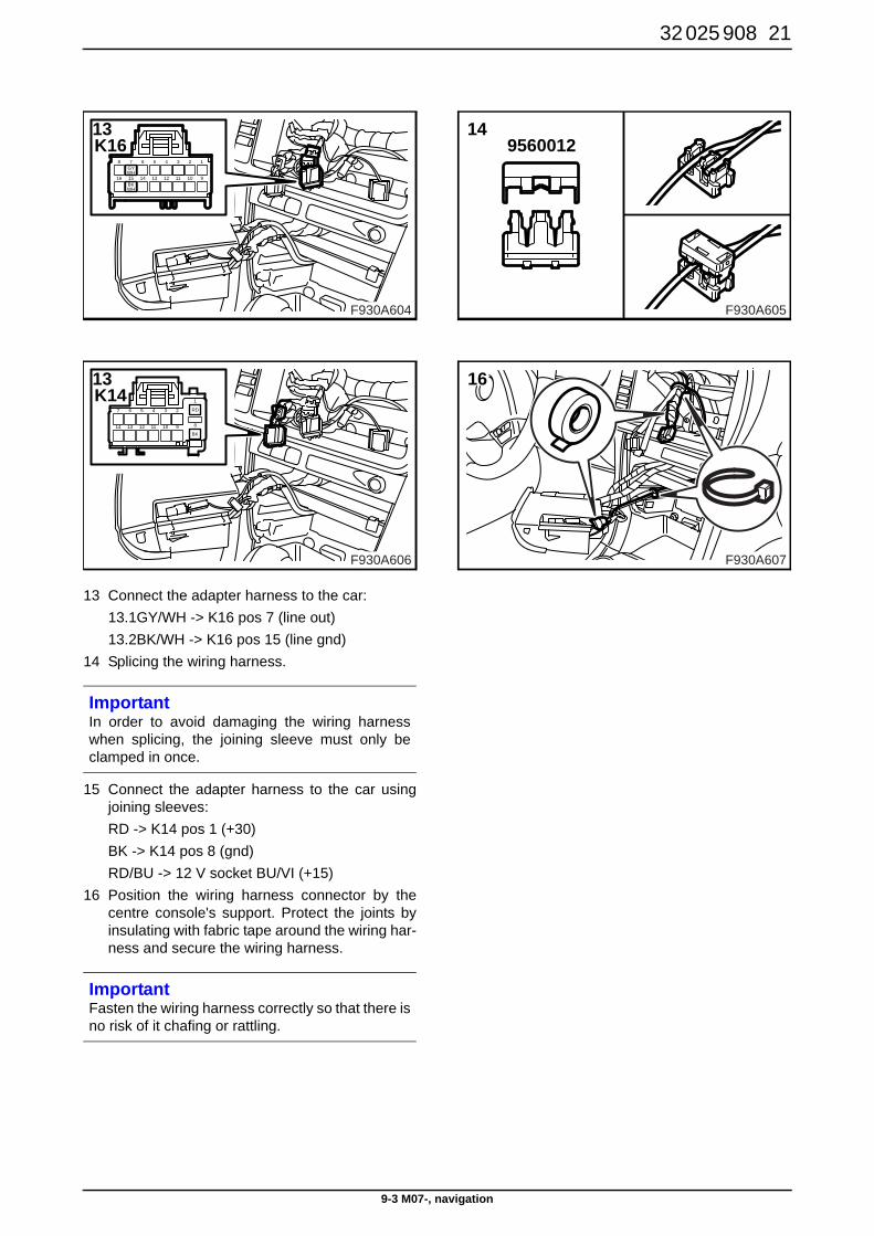
13 Connect the adapter harness to the car: 13.1GY/WH -> K16 pos 7 (line out)13.2BK/WH -> K16 pos 15 (line gnd)
14 Splicing the wiring harness.
15 Connect the adapter harness to the car usingjoining sleeves:RD -> K14 pos 1 (+30)BK -> K14 pos 8 (gnd)RD/BU -> 12 V socket BU/VI (+15)
16 Position the wiring harness connector by thecentre console's support. Protect the joints byinsulating with fabric tape around the wiring har-ness and secure the wiring harness.
ImportantIn order to avoid damaging the wiring harnesswhen splicing, the joining sleeve must only beclamped in once.
ImportantFasten the wiring harness correctly so that there isno risk of it chafing or rattling.
BK
RD3 2
9101112
45
1
8
6
13
7
14
F930A606
13K14
1
9
2
1016
8
15
7 6 5
14 13
4
12
3
11
GYWH
BKWH
F930A604
13K16
F930A605
149560012
F930A607
16
22 32 025 908
9-3 M07-, navigation
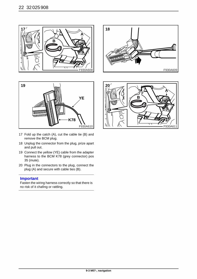
17 Fold up the catch (A), cut the cable tie (B) andremove the BCM plug.
18 Unplug the connector from the plug, prize apartand pull out.
19 Connect the yellow (YE) cable from the adapterharness to the BCM K78 (grey connector) pos35 (mute).
20 Plug in the connectors to the plug, connect theplug (A) and secure with cable ties (B).
ImportantFasten the wiring harness correctly so that there isno risk of it chafing or rattling.
F930A610
19
YE
K78
F930A608
A
B
17
F930A609
18
F930A611
A
B
20

32 025 908 23
9-3 M07-, navigation
21 Secure the adapter harness with cable ties.
22 Route the adapter harness on the right-handside of the centre console and secure with cabletie (A) and clip (B).
23 Plug in the connectors for the radio's head unit(C+D), fit the radio/navigation unit (B), and fit theretaining screws (A).
24 Fit the ACC unit (A) and the storage compart-ment/ashtray (B).
ImportantFasten the wiring harness correctly so that there isno risk of it chafing or rattling.
ImportantFasten the wiring harness correctly so that there isno risk of it chafing or rattling.
F930A614
23 A
B
D C
F930A612
21
F930A613
22
A
B
F930A615
B
A
24
24 32 025 908
9-3 M07-, navigation
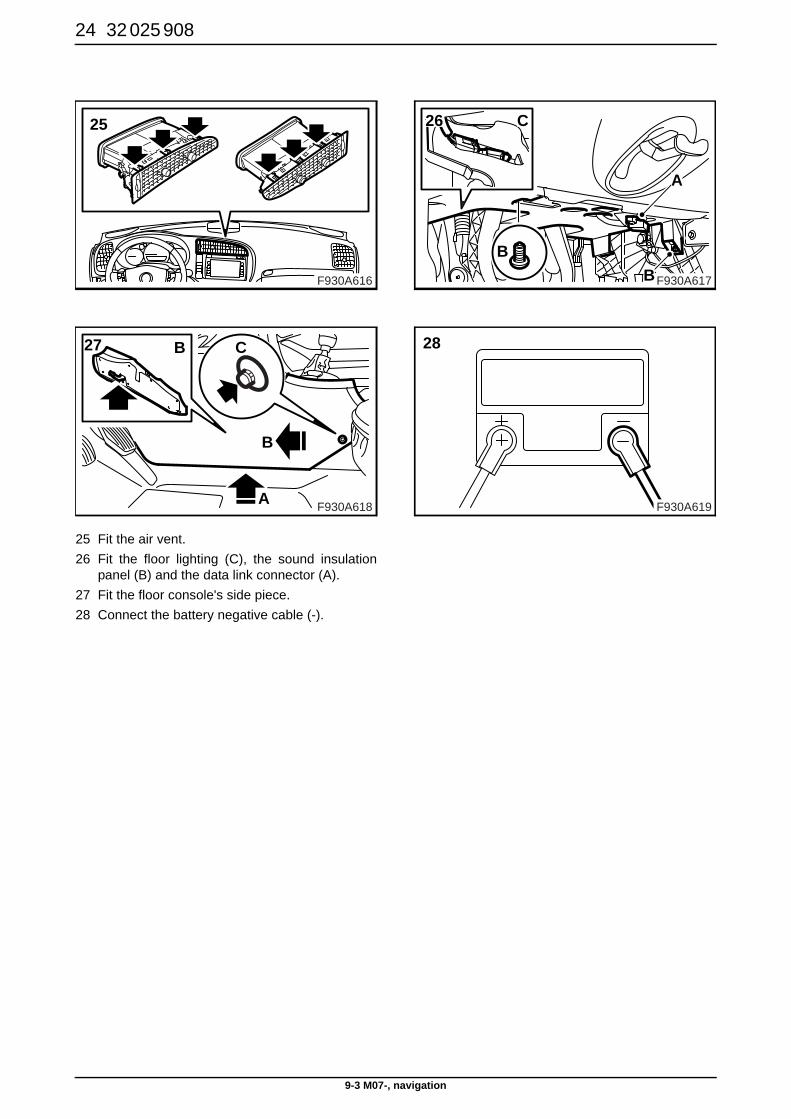
25 Fit the air vent. 26 Fit the floor lighting (C), the sound insulation
panel (B) and the data link connector (A).27 Fit the floor console's side piece. 28 Connect the battery negative cable (-).
F930A618
B
B
A
C27
F930A616
25
F930A617
B
C
A
B
26
F930A619
28
32 025 908 25
9-3 M07-, navigation
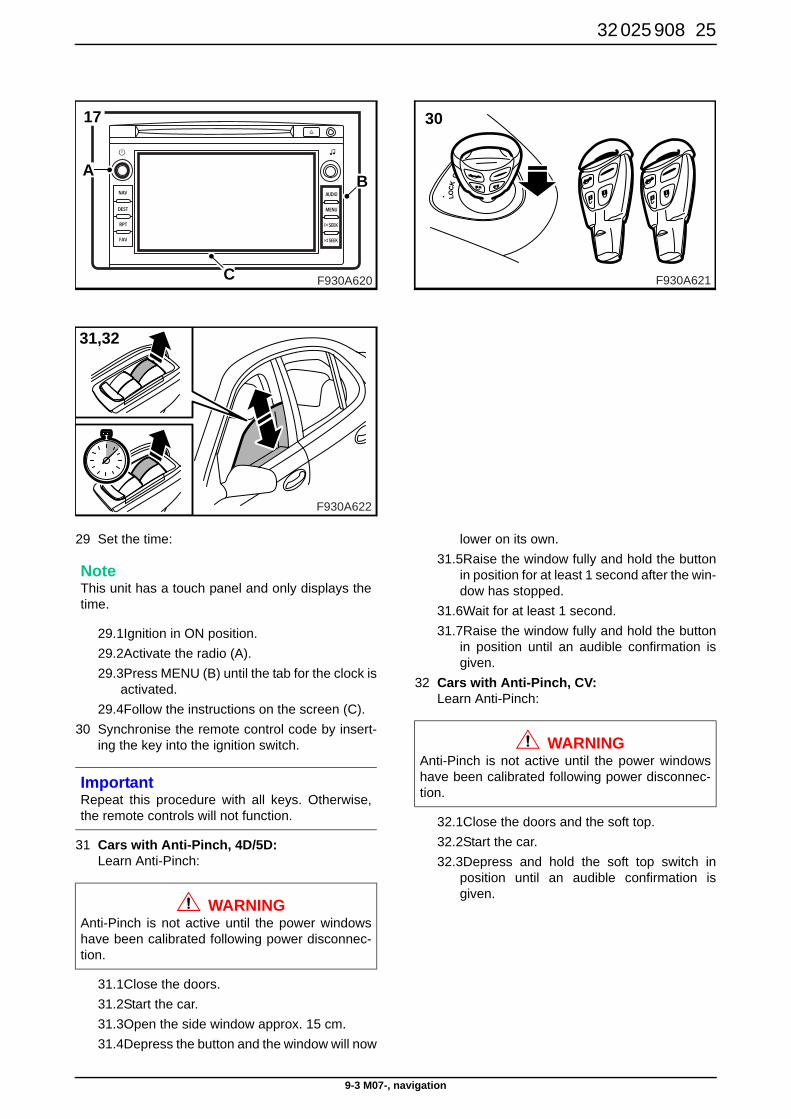
29 Set the time:
29.1Ignition in ON position.29.2Activate the radio (A).29.3Press MENU (B) until the tab for the clock is
activated. 29.4Follow the instructions on the screen (C).
30 Synchronise the remote control code by insert-ing the key into the ignition switch.
31 Cars with Anti-Pinch, 4D/5D: Learn Anti-Pinch:
31.1Close the doors. 31.2Start the car.31.3Open the side window approx. 15 cm.31.4Depress the button and the window will now
lower on its own. 31.5Raise the window fully and hold the button
in position for at least 1 second after the win-dow has stopped.
31.6Wait for at least 1 second.31.7Raise the window fully and hold the button
in position until an audible confirmation isgiven.
32 Cars with Anti-Pinch, CV: Learn Anti-Pinch:
32.1Close the doors and the soft top.32.2Start the car.32.3Depress and hold the soft top switch in
position until an audible confirmation isgiven.
NoteThis unit has a touch panel and only displays thetime.
ImportantRepeat this procedure with all keys. Otherwise,the remote controls will not function.
WARNINGAnti-Pinch is not active until the power windowshave been calibrated following power disconnec-tion.
F930A622
31,32
F930A620
B
C
A
17
F930A621
30
WARNINGAnti-Pinch is not active until the power windowshave been calibrated following power disconnec-tion.
26 32 025 908
9-5 M06-, radio/navigation
9-5 M06-, radio/navigation
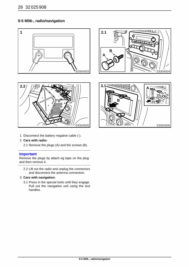
1 Disconnect the battery negative cable (-). 2 Cars with radio:
2.1 Remove the plugs (A) and the screws (B).
2.2 Lift out the radio and unplug the connectorsand disconnect the antenna connection.
3 Cars with navigation: 3.1 Press in the special tools until they engage.
Pull out the navigation unit using the toolhandles.
E930A505
2.2
E930A503
1
E930A504
2.1
AB
E930A506
A
BCLICK
3.1
ImportantRemove the plugs by attach eg tape on the plugand then remove it.
32 025 908 27
9-5 M06-, radio/navigation
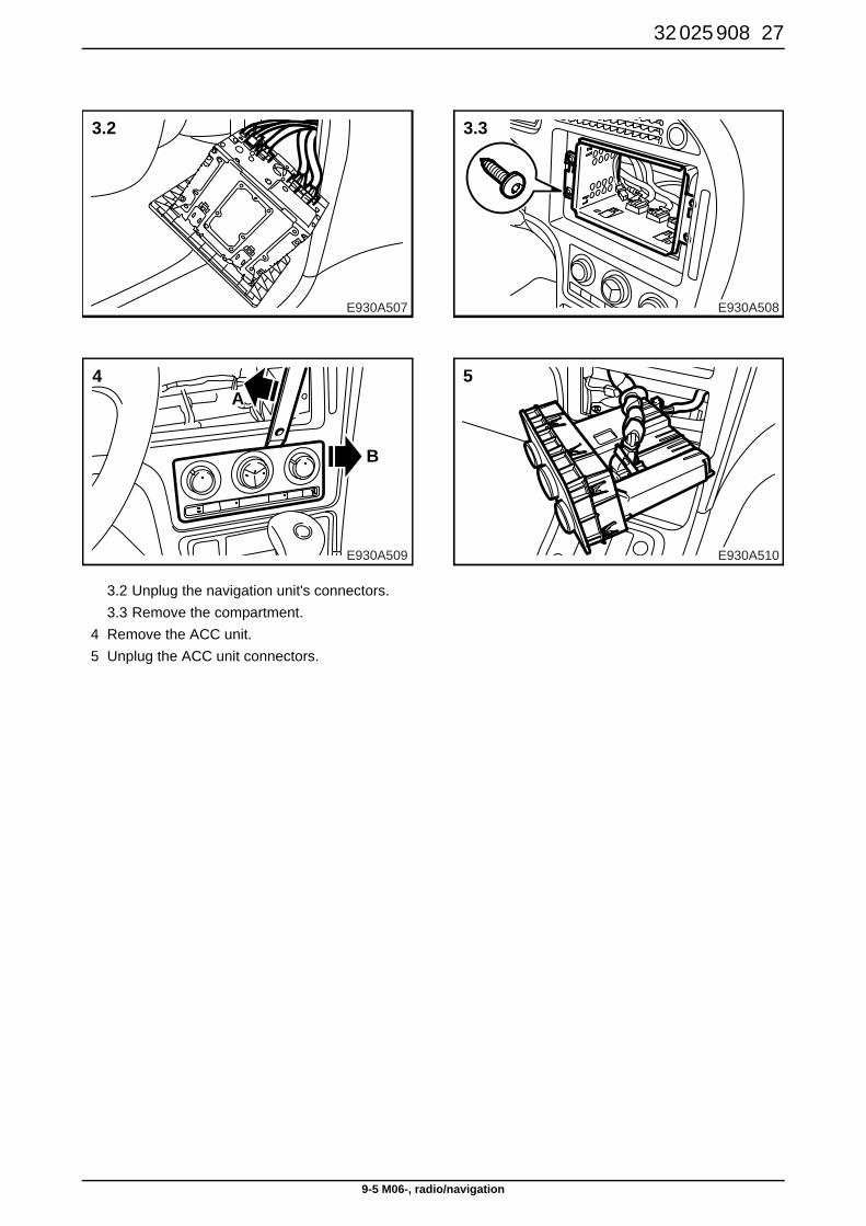
3.2 Unplug the navigation unit's connectors. 3.3 Remove the compartment.
4 Remove the ACC unit. 5 Unplug the ACC unit connectors.
E930A509
4A
B
E930A507
3.2
E930A508
3.3
E930A510
5
28 32 025 908
9-5 M06-, radio/navigation
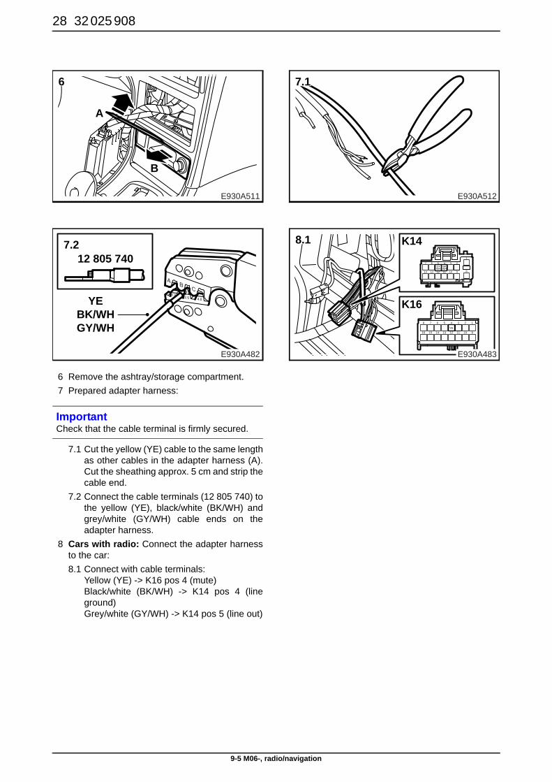
6 Remove the ashtray/storage compartment. 7 Prepared adapter harness:
7.1 Cut the yellow (YE) cable to the same lengthas other cables in the adapter harness (A).Cut the sheathing approx. 5 cm and strip thecable end.
7.2 Connect the cable terminals (12 805 740) tothe yellow (YE), black/white (BK/WH) andgrey/white (GY/WH) cable ends on theadapter harness.
8 Cars with radio: Connect the adapter harnessto the car:8.1 Connect with cable terminals:
Yellow (YE) -> K16 pos 4 (mute) Black/white (BK/WH) -> K14 pos 4 (lineground) Grey/white (GY/WH) -> K14 pos 5 (line out)
ImportantCheck that the cable terminal is firmly secured.
E930A482
12 805 740
YEBK/WHGY/WH
7.2
E930A511
6
A
B
E930A512
7.1
BKWH
GYWH
3 2
9101112
45
1
8
6
13
7
14
1
9
2
1016
8
15
7 6 5
14 13
4
12
3
11
YE
E930A483
K14
K16
8.1
32 025 908 29
9-5 M06-, radio/navigation
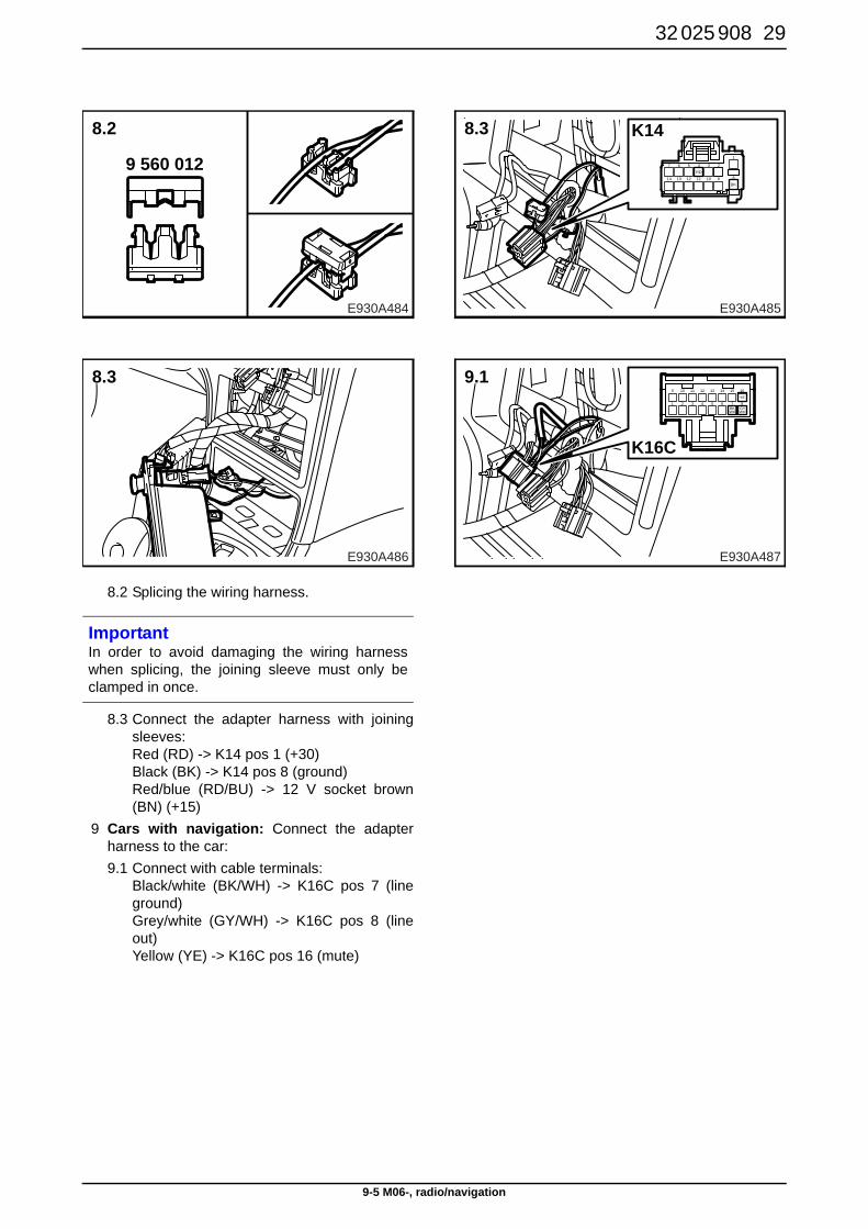
8.2 Splicing the wiring harness.
8.3 Connect the adapter harness with joiningsleeves:Red (RD) -> K14 pos 1 (+30) Black (BK) -> K14 pos 8 (ground) Red/blue (RD/BU) -> 12 V socket brown(BN) (+15)
9 Cars with navigation: Connect the adapterharness to the car:9.1 Connect with cable terminals:
Black/white (BK/WH) -> K16C pos 7 (lineground) Grey/white (GY/WH) -> K16C pos 8 (lineout) Yellow (YE) -> K16C pos 16 (mute)
ImportantIn order to avoid damaging the wiring harnesswhen splicing, the joining sleeve must only beclamped in once.
E930A486
8.3
E930A484
8.2
9 560 012RD
BK
3 2
9101112
45
1
8
6
13
7
14
K14
E930A485
8.3
1
9
2
10
3
11
4
12
5
13
6
14
BKWH
GY
YE
WH
7
15
8
16
E930A487
K16C
9.1
30 32 025 908
9-5 M06-, radio/navigation
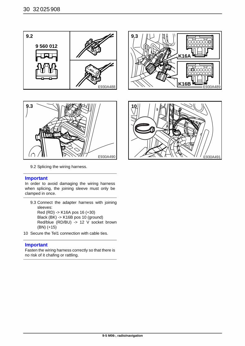
9.2 Splicing the wiring harness.
9.3 Connect the adapter harness with joiningsleeves: Red (RD) -> K16A pos 16 (+30) Black (BK) -> K16B pos 10 (ground) Red/blue (RD/BU) -> 12 V socket brown(BN) (+15)
10 Secure the Tel1 connection with cable ties.
ImportantIn order to avoid damaging the wiring harnesswhen splicing, the joining sleeve must only beclamped in once.
ImportantFasten the wiring harness correctly so that there isno risk of it chafing or rattling.
E930A490
9.3
E930A488
9.2
9 560 0121
9
2
10
3
11
4
12
5
13
6
14
RD
7
15
8
16
BK
K16A
1
9
2
10
3
11
4
12
5
13
6
14
7
15
8
16
K16BE930A489
9.3
E930A491
10
32 025 908 31
9-5 M06-, radio/navigation
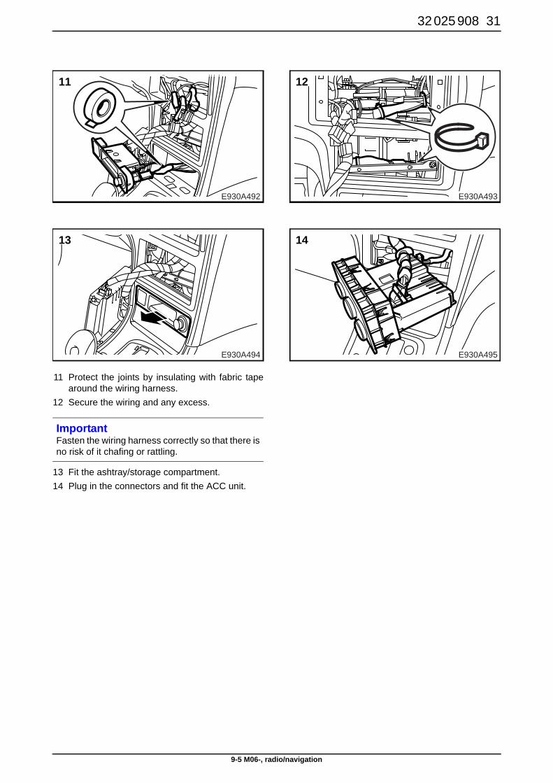
11 Protect the joints by insulating with fabric tapearound the wiring harness.
12 Secure the wiring and any excess.
13 Fit the ashtray/storage compartment. 14 Plug in the connectors and fit the ACC unit.
ImportantFasten the wiring harness correctly so that there isno risk of it chafing or rattling.
E930A494
13
E930A492
11
E930A493
12
E930A495
14
32 32 025 908
9-5 M06-, radio/navigation
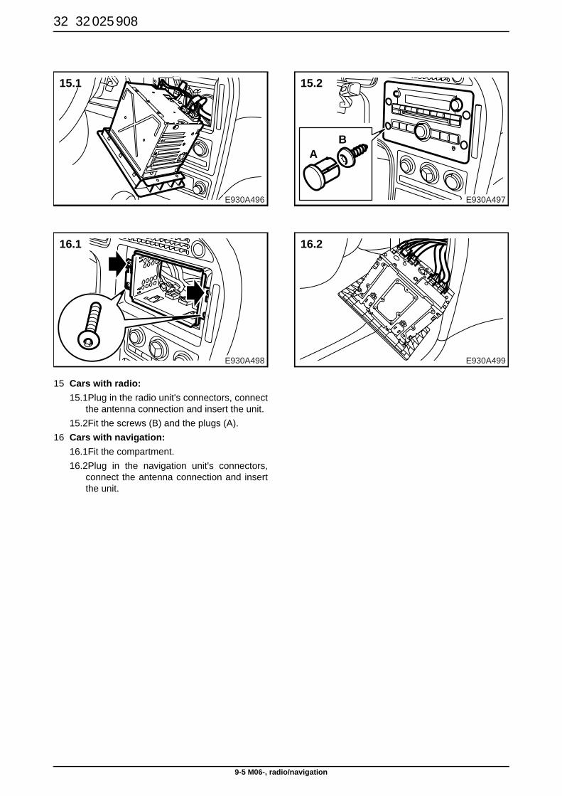
15 Cars with radio: 15.1Plug in the radio unit's connectors, connect
the antenna connection and insert the unit.15.2Fit the screws (B) and the plugs (A).
16 Cars with navigation: 16.1Fit the compartment.16.2Plug in the navigation unit's connectors,
connect the antenna connection and insertthe unit.
E930A498
16.1
E930A496
15.1
E930A497
15.2
AB
E930A499
16.2
32 025 908 33
9-5 M06-, radio/navigation
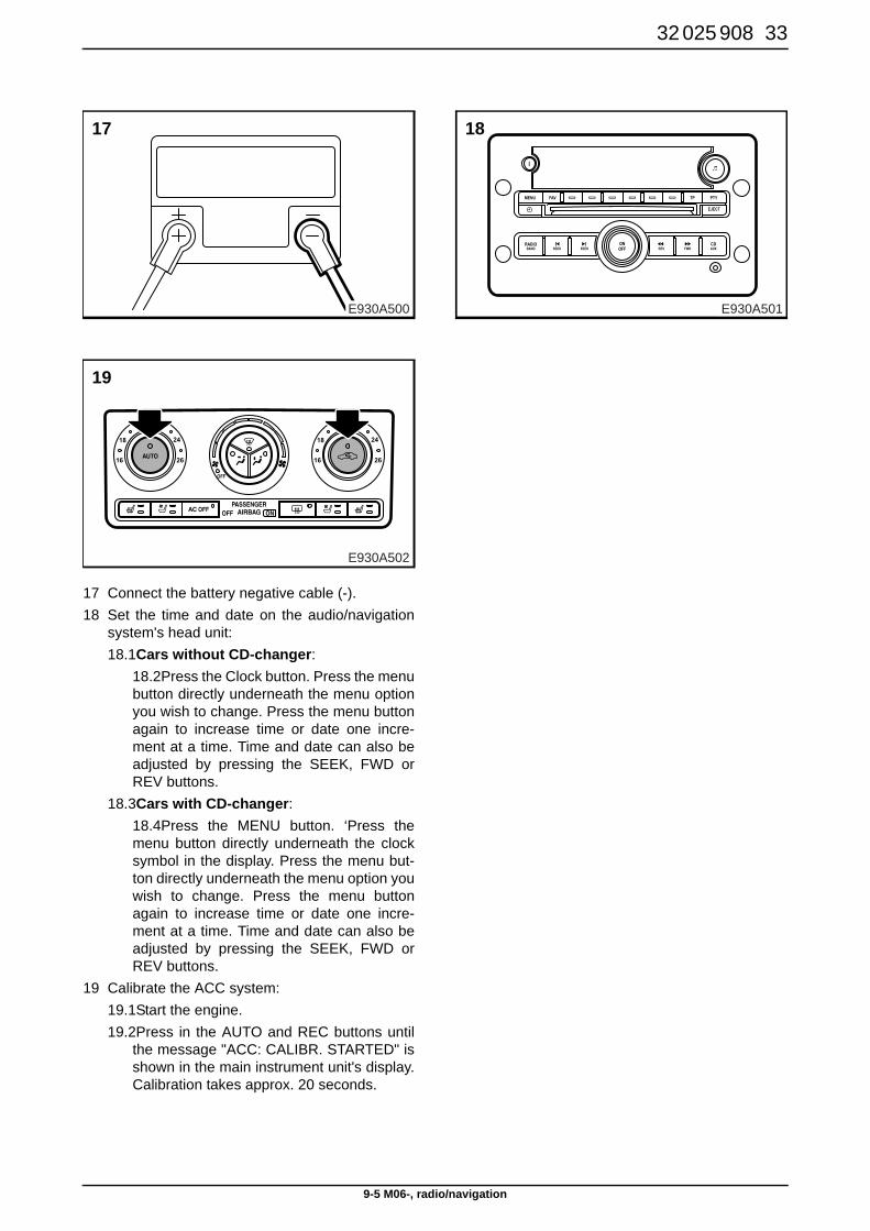
17 Connect the battery negative cable (-). 18 Set the time and date on the audio/navigation
system's head unit:18.1Cars without CD-changer:
18.2Press the Clock button. Press the menubutton directly underneath the menu optionyou wish to change. Press the menu buttonagain to increase time or date one incre-ment at a time. Time and date can also beadjusted by pressing the SEEK, FWD orREV buttons.
18.3Cars with CD-changer:18.4Press the MENU button. ‘Press themenu button directly underneath the clocksymbol in the display. Press the menu but-ton directly underneath the menu option youwish to change. Press the menu buttonagain to increase time or date one incre-ment at a time. Time and date can also beadjusted by pressing the SEEK, FWD orREV buttons.
19 Calibrate the ACC system:19.1Start the engine.19.2Press in the AUTO and REC buttons until
the message "ACC: CALIBR. STARTED" isshown in the main instrument unit's display.Calibration takes approx. 20 seconds.
E930A502
19
E930A500
17
E930A501
18