Embed Size (px)
Citation preview
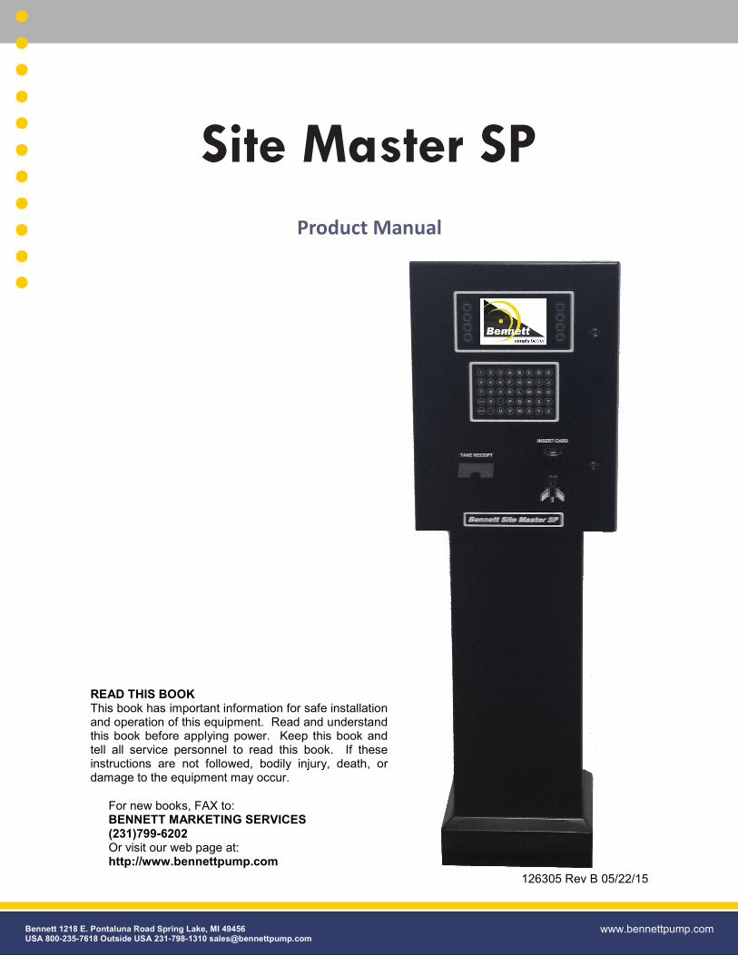
126305 Rev B 05/22/15
For new books, FAX to: BENNETT MARKETING SERVICES
(231)799-6202
Or visit our web page at: http://www.bennettpump.com
Site Master SP
Product Manual
Bennett 1218 E. Pontaluna Road Spring Lake, MI 49456 USA 800-235-7618 Outside USA 231-798-1310 [email protected]
www.bennettpump.com
READ THIS BOOK
This book has important information for safe installation and operation of this equipment. Read and understand this book before applying power. Keep this book and tell all service personnel to read this book. If these instructions are not followed, bodily injury, death, or damage to the equipment may occur.
2 126305 Rev B 05/22/15
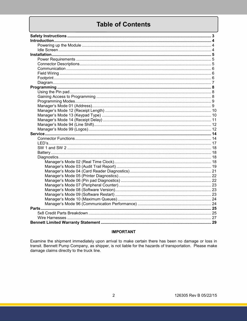
Table of Contents
Safety Instructions ................................................................................................................................. 3
Introduction ............................................................................................................................................. 4
Powering up the Module .................................................................................................................... 4
Idle Screen ......................................................................................................................................... 4
Installation ............................................................................................................................................... 5
Power Requirements ......................................................................................................................... 5
Connector Descriptions ...................................................................................................................... 5
Communication .................................................................................................................................. 6
Field Wiring ........................................................................................................................................ 6
Footprint ............................................................................................................................................. 6
Diagram .............................................................................................................................................. 7
Programming .......................................................................................................................................... 8
Using the Pin pad ............................................................................................................................... 8
Gaining Access to Programming ....................................................................................................... 8
Programming Modes .......................................................................................................................... 9
Manager’s Mode 01 (Address)........................................................................................................... 9
Manager’s Mode 12 (Receipt Length) ............................................................................................... 10
Manager’s Mode 13 (Keypad Type) .................................................................................................. 10
Manager’s Mode 14 (Receipt Delay) ................................................................................................. 11
Manager’s Mode 94 (Line Shift) ......................................................................................................... 12
Manager’s Mode 99 (Logos) .............................................................................................................. 12
Service ..................................................................................................................................................... 14
Connector Functions .......................................................................................................................... 14
LED’s .................................................................................................................................................. 17
SW 1 and SW 2 ................................................................................................................................. 18
Battery ................................................................................................................................................ 18
Diagnostics......................................................................................................................................... 18
Manager’s Mode 02 (Real Time Clock) ....................................................................................... 18
Manager’s Mode 03 (Audit Trail Report) ..................................................................................... 19
Manager’s Mode 04 (Card Reader Diagnostics) ......................................................................... 21
Manager’s Mode 05 (Printer Diagnostics) ................................................................................... 22
Manager’s Mode 06 (Pin pad Diagnostics) ................................................................................. 22
Manager’s Mode 07 (Peripheral Counter) ................................................................................... 23
Manager’s Mode 08 (Software Version) ...................................................................................... 23
Manager’s Mode 09 (Software Restart) ...................................................................................... 23
Manager’s Mode 10 (Maximum Queues) .................................................................................... 24
Manager’s Mode 96 (Communication Performance) .................................................................. 24
Parts ......................................................................................................................................................... 25
5x8 Credit Parts Breakdown .............................................................................................................. 25
Wire Harnesses ................................................................................................................................. 27
Bennett Limited Warranty Statement ................................................................................................... 29
IMPORTANT
Examine the shipment immediately upon arrival to make certain there has been no damage or loss in transit. Bennett Pump Company, as shipper, is not liable for the hazards of transportation. Please make damage claims directly to the truck line.
3 126305 Rev B 05/22/15
DANGER: Fire, explosion, injury or death will occur if fuel filters are changed by untrained personnel. Make sure only trained personnel change filters.
CAUTION: Do not drill holes in fuel dispensers. Holes can cause failure of the electronic equipment. The warranty will become void. Use only adhesive backed sign mounting brackets.
WARNING: Do not operate the equipment as a dispenser unless it is completely
WARNING: Make sure this equipment is correctly grounded. Failure to do will cause injury or damage equipment or improper operation. Improper grounding voids the warranty.
WARNING: You must have training in the operation and programming of this module before using it. READ THE OPERATORS MANUAL.
WARNING: The emergency shut-off valve (also called the fire valve, shear valve or impact valve) must be closed when service or maintenance is performed on this equipment.
WARNING: Electronic components are static sensitive. Use proper static precautions (static straps) before working on the equipment.
WARNING: To prevent electric shock, keep the electrical parts of the terminal dry.
WARNING: You must have training in the installation, service or maintenance of this equipment (dispenser, pump, console, control box or submerged pump) before working on it. Maintenance repairs must be done by authorized personnel only. Warranty work may only be performed by Bennett certified technicians.
DANGER: Disconnect all power to this equipment and associated submerged pump(s) during installation, service or any maintenance, i.e., changing filters.
DANGER: Gasoline is flammable. NO SMOKING OR OPEN FLAME.
DANGER: To prevent injury to you from vehicles and onlookers, always place a barrier around this equipment before performing service or maintenance.
WARNING ADVERTISSEMENT ADVERTENCIA
For the safe installation of this equipment, read and understand all warning and cautions. Look for these warnings:
“DANGER” means: If you do not follow the instructions, severe injury or death will occur.
“WARNING” means: If you do not follow the instructions, severe injury or death can occur.
“CAUTION” means: If you do not follow the instructions, damage can occur to the equipment.
Safety Instructions

4 126305 Rev B 05/22/15
Powering up the Module:
The module receives its power through the Power Supply. There are no power switches on the module. The only way to power on or off the module is by using the Circuit Breaker.
The Bennett Logo will appear for approximately 5 seconds when power is applied to the unit (see figure 1.1) .
After the Bennett Logo is displayed the screen will display the “Please Pay Inside” message.
NOTE: “Please Pay Inside” will be displayed only if the module and/or POS (Point of Sale) has not been configured or installed at this time (see figure 1.2). The message will return if the POS does not send a message to the module for 60 seconds.
Idle Screen:
Once everything is installed, programmed and configured properly (see installation section) the module should be ready to use. The idle screen of the module will prompt the user to either “Pay Here Credit” or “Pay Inside” (see figure 1.3).
FIGURE 1.1 - Bennett Logo
FIGURE 1.2 - “Please Pay Inside”
Introduction
FIGURE 1.3 - Idle Screen
5 126305 Rev B 05/22/15
Power Requirements:
120vac must be installed in the head of the unit and terminated on the terminal strip (see figure 2.1). Neutral and Hot will be labeled on the terminal strip. The Power Supply will be factory wired to the terminal strip.
The Power Supply converts the 120vac into the 12vdc and 24vdc needed for the module to operate.
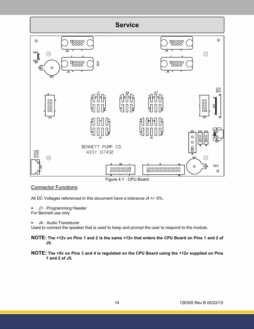
The module receives its power from the Power Supply through the J5 connector, on the CPU Board (see figure 2.2).
The module uses a 12vdc voltage source and 24vdc voltage source. Both sources are received through the J5 connector.
The following components use the 12vdc voltage source:
• Card Reader
• Display Backlight
• Receipt Printer Data
The following components use the 24vdc voltage source:
• Receipt Printer Power
• Display
Connector Descriptions:
All peripherals are plugged into the CPU Board. Following is a description of each connector.
• J1 - Programming Header • J4 - Audio Transducer • J5 - Power Input/Data Link • J6 - Card Swipe Reader • J7 - Receipt Printer Power • J8 - Receipt Printer Data • J9 - Auxiliary / Natural Gas Comm. Hub Board • J12 - Alpha Numeric Pin pad or Credit only Keypad • J13 - Left Side Soft Keys • J14 - Right Side Soft Keys • J17 - Fan Assembly • J19 - Display Data • J20 - Display Backlight • J22 - Amulet Chip Programming Interface
See the Service Section for more details on the connector pin-outs.
Installation
FIGURE 2.2 - J5 Incoming Power
J5 Connector
Terminal Strip
FIGURE 2.1 - Power
Power Supply
6 126305 Rev B 05/22/15
DANGER: Circuit Breaker must be off prior to plugging anything into or unplugging anything
from the module.
DANGER: When inserting the plugs into the connectors, make sure that the locking tab points
to the right side of the connector. Gently tug the wires to verify that the locking tab is engaged. Failure to plug these in correctly will damage the module!
Communication:
The data for the module is also received through the J5 connector. The module communicates directly to the POS via the strip in the head of the unit and Interconnect Box (see figure 2.2 - on previous page).
NOTE: • The Pedestal must be mounted at least 18” from any dispenser or any area that’s classified
as Class 1 Division 1.
• Installation must be in accordance with National Electric Code (NFPA 70), the Automotive and Marine Service Code (NFPA 30A) and all State and Local Codes.
• Use only Underwriters Listed Threaded Rigid Conduit and Listed Sealing Fitting with conductor seals.
• Field connections are done in the Upper Electrical Enclosure. Wire must extend 60 inches above base of the unit to make Electrical Connections.
• All conductors are to be stranded copper with THHN and gas and oil resistant insulation per National Electrical Code.
• Do not use wire smaller than 18 gauge.
• These data wires should be twisted together at least 3 times per foot to reduce the effects of electrical noise on the communication circuit. Due to the risk of noise causing possible problems with communication, Bennett highly recommends the use of the twisted wires, but does not require it.
• Do not use wire nuts on Data Lines. Do not splice Data wires. They must be direct runs.
• It is acceptable to pull the Data Lines in the same conduit as the terminal’s power.
• Shims should only be used under Bolts to ensure the unit is level. Improper shimming that results in misaligned frame is NOT covered under the Bennett Limited Warranty.
Field Wiring Diagram on Next Page�
Footprint:
Installation (continued...)
Field Wiring:
Data wires required for installation: (1) 18 gauge for Data +
(1) 18 gauge for Common
(1) 18 gauge for Data -
7 126305 Rev B 05/22/15
Installation (continued...)
FIGURE 2.3 - Field Wiring Diagram (Power)
FIGURE 2.4 - Field Wiring Diagram (Communication)
8 126305 Rev B 05/22/15
Programming
Gaining Access to Manager’s Mode:
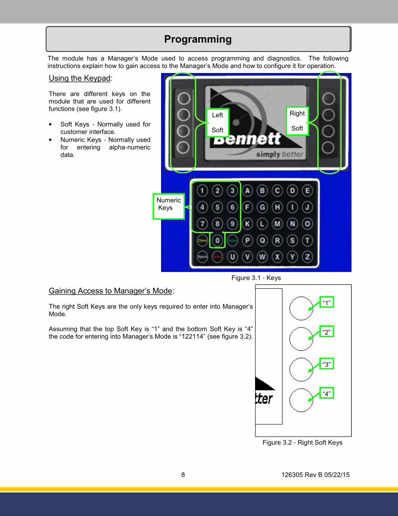
The right Soft Keys are the only keys required to enter into Manager’s Mode.
Assuming that the top Soft Key is “1” and the bottom Soft Key is “4” the code for entering into Manager’s Mode is “122114” (see figure 3.2).
Programming
The module has a Manager’s Mode used to access programming and diagnostics. The following instructions explain how to gain access to the Manager’s Mode and how to configure it for operation.
Using the Keypad:
There are different keys on the module that are used for different functions (see figure 3.1).
• Soft Keys - Normally used for customer interface.
• Numeric Keys - Normally used for entering alpha-numeric data.
Figure 3.2 - Right Soft Keys
“1”
“2”
“3”
“4”
Figure 3.1 - Keys
Left
Soft
Right
Soft
Numeric Keys
9 126305 Rev B 05/22/15
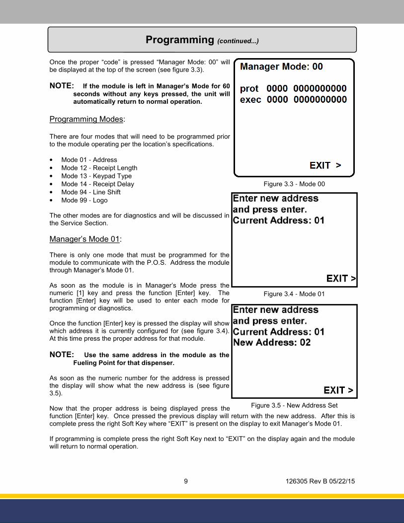
Once the proper “code” is pressed “Manager Mode: 00” will be displayed at the top of the screen (see figure 3.3).
NOTE: If the module is left in Manager’s Mode for 60
seconds without any keys pressed, the unit will automatically return to normal operation.
Programming Modes:
There are four modes that will need to be programmed prior to the module operating per the location’s specifications.
• Mode 01 - Address
• Mode 12 - Receipt Length
• Mode 13 - Keypad Type
• Mode 14 - Receipt Delay
• Mode 94 - Line Shift
• Mode 99 - Logo
The other modes are for diagnostics and will be discussed in the Service Section.
Manager’s Mode 01:
There is only one mode that must be programmed for the module to communicate with the P.O.S. Address the module through Manager’s Mode 01.
As soon as the module is in Manager’s Mode press the numeric [1] key and press the function [Enter] key. The function [Enter] key will be used to enter each mode for programming or diagnostics.
Once the function [Enter] key is pressed the display will show which address it is currently configured for (see figure 3.4). At this time press the proper address for that module.
NOTE: Use the same address in the module as the
Fueling Point for that dispenser.
As soon as the numeric number for the address is pressed the display will show what the new address is (see figure 3.5).
Now that the proper address is being displayed press the function [Enter] key. Once pressed the previous display will return with the new address. After this is complete press the right Soft Key where “EXIT” is present on the display to exit Manager’s Mode 01.
If programming is complete press the right Soft Key next to “EXIT” on the display again and the module will return to normal operation.
Programming (continued...)
Figure 3.3 - Mode 00
Figure 3.4 - Mode 01
Figure 3.5 - New Address Set
10 126305 Rev B 05/22/15
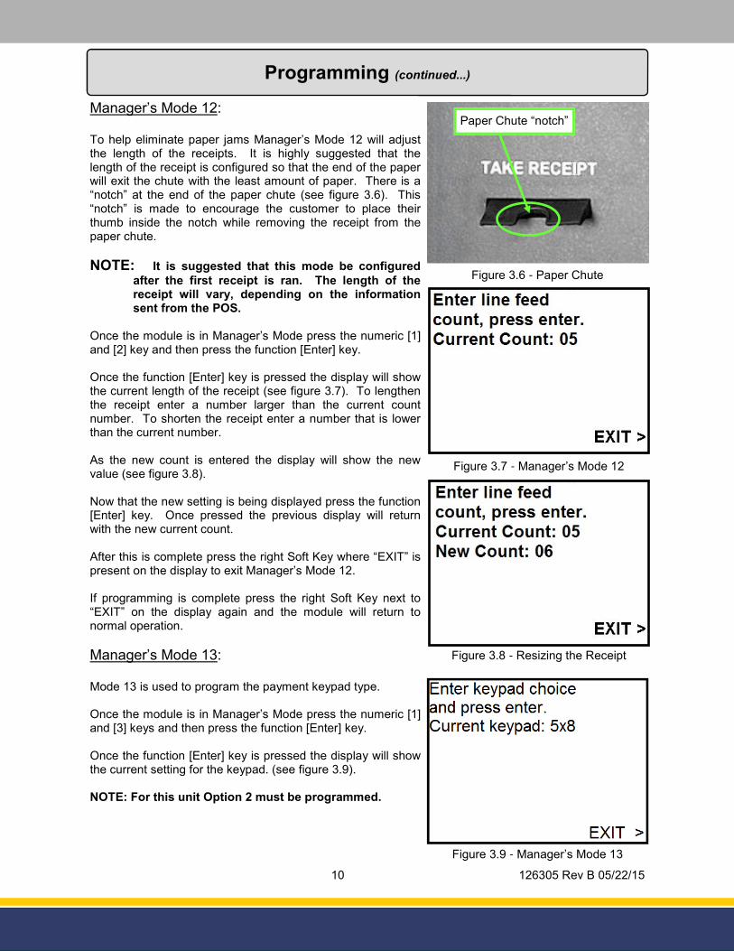
Manager’s Mode 12:
To help eliminate paper jams Manager’s Mode 12 will adjust the length of the receipts. It is highly suggested that the length of the receipt is configured so that the end of the paper will exit the chute with the least amount of paper. There is a “notch” at the end of the paper chute (see figure 3.6). This “notch” is made to encourage the customer to place their thumb inside the notch while removing the receipt from the paper chute.
NOTE: It is suggested that this mode be configured
after the first receipt is ran. The length of the receipt will vary, depending on the information sent from the POS.
Once the module is in Manager’s Mode press the numeric [1] and [2] key and then press the function [Enter] key.
Once the function [Enter] key is pressed the display will show the current length of the receipt (see figure 3.7). To lengthen the receipt enter a number larger than the current count number. To shorten the receipt enter a number that is lower than the current number.
As the new count is entered the display will show the new value (see figure 3.8).
Now that the new setting is being displayed press the function [Enter] key. Once pressed the previous display will return with the new current count.
After this is complete press the right Soft Key where “EXIT” is present on the display to exit Manager’s Mode 12.
If programming is complete press the right Soft Key next to “EXIT” on the display again and the module will return to normal operation.
Manager’s Mode 13:
Mode 13 is used to program the payment keypad type.
Once the module is in Manager’s Mode press the numeric [1] and [3] keys and then press the function [Enter] key.
Once the function [Enter] key is pressed the display will show the current setting for the keypad. (see figure 3.9).
NOTE: For this unit Option 2 must be programmed.
Programming (continued...)
Figure 3.6 - Paper Chute
Paper Chute “notch”
Figure 3.7 - Manager’s Mode 12
Figure 3.8 - Resizing the Receipt
Figure 3.9 - Manager’s Mode 13
11 126305 Rev B 05/22/15
Programming (continued...)
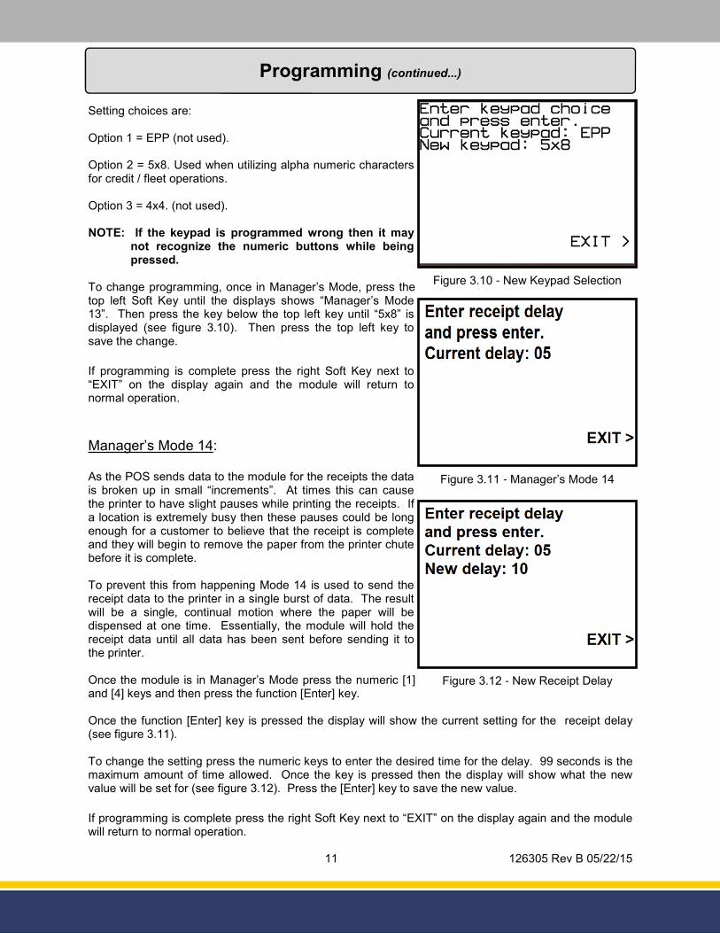
Setting choices are:
Option 1 = EPP (not used).
Option 2 = 5x8. Used when utilizing alpha numeric characters for credit / fleet operations.
Option 3 = 4x4. (not used).
NOTE: If the keypad is programmed wrong then it may not recognize the numeric buttons while being pressed.
To change programming, once in Manager’s Mode, press the top left Soft Key until the displays shows “Manager’s Mode 13”. Then press the key below the top left key until “5x8” is displayed (see figure 3.10). Then press the top left key to save the change.
If programming is complete press the right Soft Key next to “EXIT” on the display again and the module will return to normal operation.
Manager’s Mode 14:
As the POS sends data to the module for the receipts the data is broken up in small “increments”. At times this can cause the printer to have slight pauses while printing the receipts. If a location is extremely busy then these pauses could be long enough for a customer to believe that the receipt is complete and they will begin to remove the paper from the printer chute before it is complete.
To prevent this from happening Mode 14 is used to send the receipt data to the printer in a single burst of data. The result will be a single, continual motion where the paper will be dispensed at one time. Essentially, the module will hold the receipt data until all data has been sent before sending it to the printer.
Once the module is in Manager’s Mode press the numeric [1] and [4] keys and then press the function [Enter] key.
Once the function [Enter] key is pressed the display will show the current setting for the receipt delay (see figure 3.11).
To change the setting press the numeric keys to enter the desired time for the delay. 99 seconds is the maximum amount of time allowed. Once the key is pressed then the display will show what the new value will be set for (see figure 3.12). Press the [Enter] key to save the new value.
If programming is complete press the right Soft Key next to “EXIT” on the display again and the module will return to normal operation.
Figure 3.11 - Manager’s Mode 14
Figure 3.12 - New Receipt Delay
Figure 3.10 - New Keypad Selection
12 126305 Rev B 05/22/15
Programming (continued...)
Manager’s Mode 94:
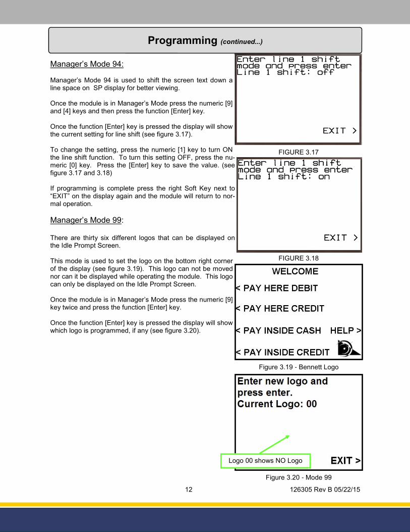
Manager’s Mode 94 is used to shift the screen text down a line space on SP display for better viewing.
Once the module is in Manager’s Mode press the numeric [9] and [4] keys and then press the function [Enter] key.
Once the function [Enter] key is pressed the display will show the current setting for line shift (see figure 3.17).
To change the setting, press the numeric [1] key to turn ON the line shift function. To turn this setting OFF, press the nu-meric [0] key. Press the [Enter] key to save the value. (see figure 3.17 and 3.18)
If programming is complete press the right Soft Key next to “EXIT” on the display again and the module will return to nor-mal operation.
Manager’s Mode 99:
There are thirty six different logos that can be displayed on the Idle Prompt Screen.
This mode is used to set the logo on the bottom right corner of the display (see figure 3.19). This logo can not be moved nor can it be displayed while operating the module. This logo can only be displayed on the Idle Prompt Screen.
Once the module is in Manager’s Mode press the numeric [9] key twice and press the function [Enter] key.
Once the function [Enter] key is pressed the display will show which logo is programmed, if any (see figure 3.20).
FIGURE 3.17
FIGURE 3.18
Figure 3.19 - Bennett Logo
Figure 3.20 - Mode 99
Logo 00 shows NO Logo

13 126305 Rev B 05/22/15
Programming (continued...)
There are currently thirty six options that are available for this mode:
NOTE: This list will increase through time so if the desired logo doesn’t seem available please
contact Bennett Pump Company for a complete list of logos.
As soon as the number for the desired logo is pressed the current logo will disappear. The new logo will not appear until the function [Enter] key is pressed (see figure 3.21).
After this is complete press the right Soft Key where “EXIT” is present on the display to exit Manager’s Mode 99.
If programming is complete press the right Soft Key next to “EXIT” on the display again and the module will return to normal operation.
00 - No Logo
01 - 76 Logo
02 - Air Products Logo
03 - Arco Logo
04 - Beacon Logo
05 - Bennett Logo
06 - BP Logo
07 - Chevron Logo
08 - Citgo Logo
09 - Clark Logo
10 - Conoco Logo
11 - Conoco Phillips Logo
12 - Exxon Logo
13 - Flying J Logo
14 - Fuel Depot Logo
15 - Getty Logo
16 - GoGas Logo
17 - Gulf Logo
18 - Hess Logo
19 - Irving Logo
20 - Lukoil Logo
21 - Mapco Logo
22 - Marathon Logo
23 - Mobil Logo
24 - Phillips 66 Logo
25 - Pure Oil Eagle Logo
26 - Pure Oil Logo
27 - Sapp Brothers Logo
28 - Shamrock Logo
29 - Shell Logo
30 - Sinclair Logo
31 - Sunoco Logo
32 - Tesoro Logo
33 - Texaco Logo
34 - Valero Logo
35 - VP Racing Fuels Logo
Figure 3.21 - Selecting Logo
14 126305 Rev B 05/22/15
Figure 4.1 - CPU Board
Service
Connector Functions:
All DC Voltages referenced in this document have a tolerance of +/- 5%.
• J1 - Programming Header For Bennett use only.
• J4 - Audio Transducer Used to connect the speaker that is used to beep and prompt the user to respond to the module.
NOTE: The +12v on Pins 1 and 2 is the same +12v that enters the CPU Board on Pins 1 and 2 of
J5.
NOTE: The +5v on Pins 3 and 4 is regulated on the CPU Board using the +12v supplied on Pins 1 and 2 of J5.
15 126305 Rev B 05/22/15
Service (continued...)
• J5 - Module Power, Module RS-485
Used to connect the debit system to an external power supply and connect the debit system’s RS-485 interface to the 3rd part controller.
• J6 (COM 0) - Card Swipe
This is dedicated to RS-232 used to interface the card swipe reader.
NOTE: The +12v on Pin 4 is the same +12v that enters the CPU Board on Pins 1 and 2 of J5.
• J7 - Receipt Printer Power
NOTE: The same +24v on Pins 1 and 2 is the same +24v from Pins 3 and 4 of J5.
NOTE: The same +12v on Pin 3 is the same +12v from Pins 1 and 2 of J5.
NOTE: The +5v is regulated on the CPU Board using the +12v supplied on Pins 1 and 2 of J5.
• J8 (COM 1) - Receipt Printer This is dedicated to RS-232 used to interface the receipt printer.
J9 (COM 2) - Auxiliary Connector / Natural Gas Com. Hub Board
J10 - Not Used
NOTE: The same +24v on Pins 1 and 2 is the same +24v from Pins 3 and 4 of J5.
NOTE: The same +12v on Pin 3 is the same +12v from Pins 1 and 2 of J5.
NOTE: The +5v is regulated on the CPU Board using the +12v supplied on Pins 1 and 2 of J5.
J11 (COM 3) - Not Used
NOTE: The +5v on Pins 4 and 6 is regulated on the CPU Board from the +12v supplied on Pins 1
and 2 of J5.
• J12 - Alpha Numeric Keyboard or Credit Only Keypad
This is used to connect the Alpha Numeric Keypad to the keypad matrix.
Pins: Pins:
1. +12v 6. RS-485 Return
2. +12v 7. RS-485 -
3. +24v 8. N/C
4. +24v 9. Ground
5. RS-485 + 10. Ground
16 126305 Rev B 05/22/15
Service (continued...)
• J13 - Right Side Soft Keys
This is used to connect the left side soft key push buttons to the keypad matrix.
• J14 - Left Side Soft Keys
This is used to connect the right side soft key push buttons to the keypad matrix.
• J17 - Auxiliary Power Used for peripheral power requirements
NOTE: The same +24v on Pins 1 and 2 is the same +24v from Pins 3 and 4 of J5.
NOTE: The same +12v on Pin 3 is the same +12v from Pins 1 and 2 of J5.
NOTE: The +5v is regulated on the CPU Board using the +12v supplied on Pins 1 and 2 of J5.
• J19 - Display Data
Connects to the flex ribbon coming from the graphics display. This ribbon contains the display data and display power.
• J20 - Display Backlight Provides +24v to the display for backlighting.
• J22 - Amulet Chip Programming
This connector is used for programming the Amulet Chip. Used for updating the SP software.
17 126305 Rev B 05/22/15
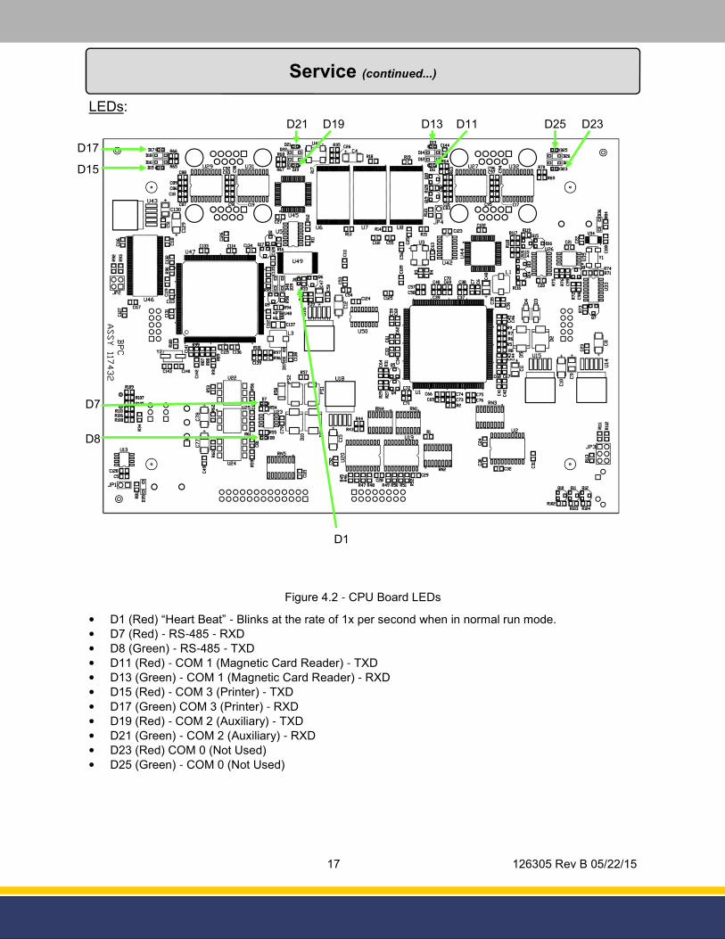
LEDs:
Service (continued...)
Figure 4.2 - CPU Board LEDs
D25 D21 D19 D13 D11
D1
D7
D8
D15
D17
D23
• D1 (Red) “Heart Beat” - Blinks at the rate of 1x per second when in normal run mode.
• D7 (Red) - RS-485 - RXD
• D8 (Green) - RS-485 - TXD
• D11 (Red) - COM 1 (Magnetic Card Reader) - TXD
• D13 (Green) - COM 1 (Magnetic Card Reader) - RXD
• D15 (Red) - COM 3 (Printer) - TXD
• D17 (Green) COM 3 (Printer) - RXD
• D19 (Red) - COM 2 (Auxiliary) - TXD
• D21 (Green) - COM 2 (Auxiliary) - RXD
• D23 (Red) COM 0 (Not Used)
• D25 (Green) - COM 0 (Not Used)

18 126305 Rev B 05/22/15
SW 1 and SW 2:
These switches are used in conjunction with J1 (Programming Header). With the switches moved away from the dot the unit is ready for receiving a new code. If the switches are moved towards the dot the unit is in normal run mode. There is a white dot on the board to indicate normal run mode.
NOTE: Use “SPM/SPP Programming Instructions” (Part Number 126036) for instructions on how to program the unit.
CAUTION: This is only to be used with the instruction of Bennett Pump Company.
Battery:
Refer to figure 4.1 for the location of the battery. BT2 - Lithium Button Cell Supports both real time clock (RTC).
NOTE: When this battery is fully discharged the RTC stops working and the debit system will
show a permanent door open condition.
Diagnostics:
There are ten diagnostic modes available with the module. These modes are used to help troubleshoot the software, keypad, printer, card reader or encryption. Here is a list of diagnostic modes:
• Mode 02 - Real Time Clock (RTC) Change
• Mode 03 - Audit Trail Print
• Mode 04 - Card Reader Test
• Mode 05 - Printer Test
• Mode 06 - Keypad Test
• Mode 07 - Power Control Counters
• Mode 08 - Software Version
• Mode 09 - Software Restart
• Mode 10 - Maximum Queue
• Mode 96 - Communication Performance
To gain access to these modes follow the same instructions used to enter the programming modes (see page 9).
Manager’s Mode 02:
There is a Real Time Clock (RTC) that the system uses to track two different Audit Events.
1. Software Restarts
2. RTC Changes
Use these events to help show how many times the software in the module has restarted and how many times the Real Time Clock has been changed. Each event will be stamped with a date and time.
NOTE: There is no way to reset these events.
Service (continued...)
19 126305 Rev B 05/22/15
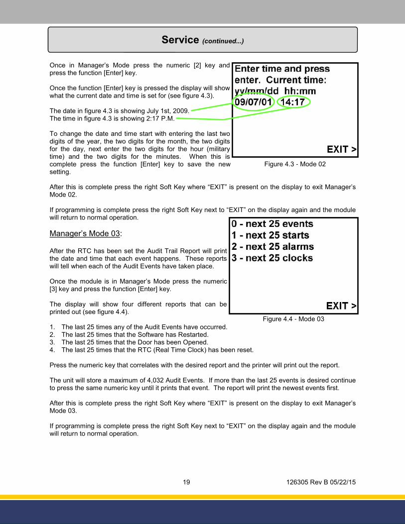
Once in Manager’s Mode press the numeric [2] key and press the function [Enter] key.
Once the function [Enter] key is pressed the display will show what the current date and time is set for (see figure 4.3).
The date in figure 4.3 is showing July 1st, 2009. The time in figure 4.3 is showing 2:17 P.M.
To change the date and time start with entering the last two digits of the year, the two digits for the month, the two digits for the day, next enter the two digits for the hour (military time) and the two digits for the minutes. When this is complete press the function [Enter] key to save the new setting.
After this is complete press the right Soft Key where “EXIT” is present on the display to exit Manager’s Mode 02.
If programming is complete press the right Soft Key next to “EXIT” on the display again and the module will return to normal operation.
Manager’s Mode 03:
After the RTC has been set the Audit Trail Report will print the date and time that each event happens. These reports will tell when each of the Audit Events have taken place.
Once the module is in Manager’s Mode press the numeric [3] key and press the function [Enter] key.
The display will show four different reports that can be printed out (see figure 4.4).
1. The last 25 times any of the Audit Events have occurred. 2. The last 25 times that the Software has Restarted. 3. The last 25 times that the Door has been Opened. 4. The last 25 times that the RTC (Real Time Clock) has been reset.
Press the numeric key that correlates with the desired report and the printer will print out the report.
The unit will store a maximum of 4,032 Audit Events. If more than the last 25 events is desired continue to press the same numeric key until it prints that event. The report will print the newest events first.
After this is complete press the right Soft Key where “EXIT” is present on the display to exit Manager’s Mode 03.
If programming is complete press the right Soft Key next to “EXIT” on the display again and the module will return to normal operation.
Service (continued...)
Figure 4.3 - Mode 02
Figure 4.4 - Mode 03
20 126305 Rev B 05/22/15
If programming is complete press the right Soft Key next to “EXIT” on the display again and the module will return to normal operation.
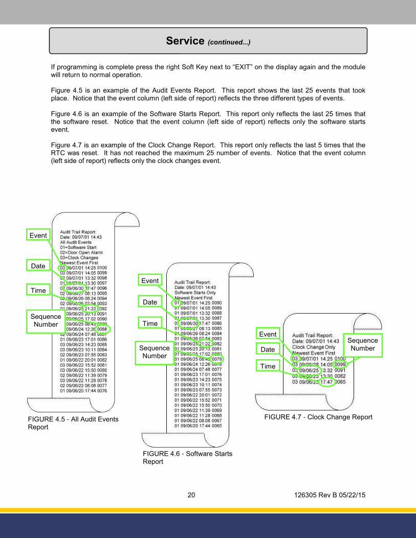
Figure 4.5 is an example of the Audit Events Report. This report shows the last 25 events that took place. Notice that the event column (left side of report) reflects the three different types of events.
Figure 4.6 is an example of the Software Starts Report. This report only reflects the last 25 times that the software reset. Notice that the event column (left side of report) reflects only the software starts event.
Figure 4.7 is an example of the Clock Change Report. This report only reflects the last 5 times that the RTC was reset. It has not reached the maximum 25 number of events. Notice that the event column (left side of report) reflects only the clock changes event.
Service (continued...)
FIGURE 4.5 - All Audit Events Report
Event
Date
Time
Sequence Number
FIGURE 4.6 - Software Starts Report
Event
Date
Time
Sequence Number
FIGURE 4.7 - Clock Change Report
Event
Date
Time
Sequence Number
21 126305 Rev B 05/22/15
FIGURE 4.10 - Tracks are Operational
Service (continued...)
Manager’s Mode 04:
This mode is used to test the card reader for the module.
Once the module is in Manager’s Mode press the numeric [4] key and press the function [Enter] key.
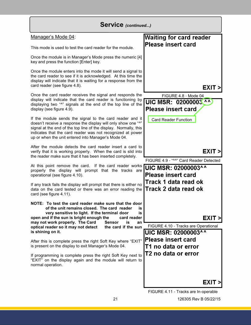
Once the module enters into the mode it will send a signal to the card reader to see if it is acknowledged. At this time the display will indicate that it is waiting for a response from the card reader (see figure 4.8).
Once the card reader receives the signal and responds the display will indicate that the card reader is functioning by displaying two “^” signals at the end of the top line of the display (see figure 4.9).
If the module sends the signal to the card reader and it doesn’t receive a response the display will only show one “^” signal at the end of the top line of the display. Normally, this indicates that the card reader was not recognized at power up or when the unit entered into Manager’s Mode 04.
After the module detects the card reader insert a card to verify that it is working properly. When the card is slid into the reader make sure that it has been inserted completely.
At this point remove the card. If the card reader works properly the display will prompt that the tracks are operational (see figure 4.10).
If any track fails the display will prompt that there is either no data on the card tested or there was an error reading the card (see figure 4.11).
NOTE: To test the card reader make sure that the door of the unit remains closed. The card reader is very sensitive to light. If the terminal door is open and if the sun is bright enough the card reader may not work properly. The Card Sensor is an optical reader so it may not detect the card if the sun is shining on it.
After this is complete press the right Soft Key where “EXIT” is present on the display to exit Manager’s Mode 04.
If programming is complete press the right Soft Key next to “EXIT” on the display again and the module will return to normal operation.
FIGURE 4.8 - Mode 04
FIGURE 4.9 - “^^” Card Reader Detected
Card Reader Function
FIGURE 4.11 - Tracks are In-operable
22 126305 Rev B 05/22/15
Service Service (continued...)
Manager’s Mode 05:
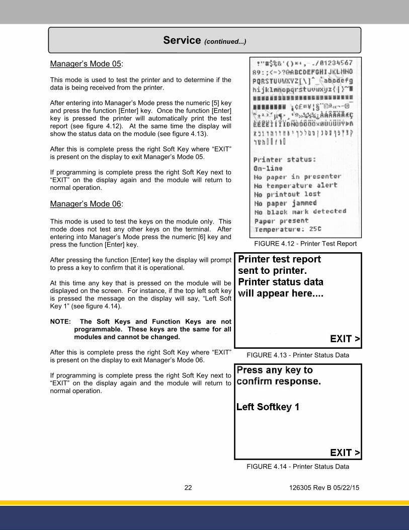
This mode is used to test the printer and to determine if the data is being received from the printer.
After entering into Manager’s Mode press the numeric [5] key and press the function [Enter] key. Once the function [Enter] key is pressed the printer will automatically print the test report (see figure 4.12). At the same time the display will show the status data on the module (see figure 4.13).
After this is complete press the right Soft Key where “EXIT” is present on the display to exit Manager’s Mode 05.
If programming is complete press the right Soft Key next to “EXIT” on the display again and the module will return to normal operation.
Manager’s Mode 06:
This mode is used to test the keys on the module only. This mode does not test any other keys on the terminal. After entering into Manager’s Mode press the numeric [6] key and press the function [Enter] key.
After pressing the function [Enter] key the display will prompt to press a key to confirm that it is operational.
At this time any key that is pressed on the module will be displayed on the screen. For instance, if the top left soft key is pressed the message on the display will say, “Left Soft Key 1” (see figure 4.14).
NOTE: The Soft Keys and Function Keys are not programmable. These keys are the same for all modules and cannot be changed.
After this is complete press the right Soft Key where “EXIT” is present on the display to exit Manager’s Mode 06.
If programming is complete press the right Soft Key next to “EXIT” on the display again and the module will return to normal operation.
FIGURE 4.12 - Printer Test Report
FIGURE 4.13 - Printer Status Data
FIGURE 4.14 - Printer Status Data
23 126305 Rev B 05/22/15
Service Service (continued...)
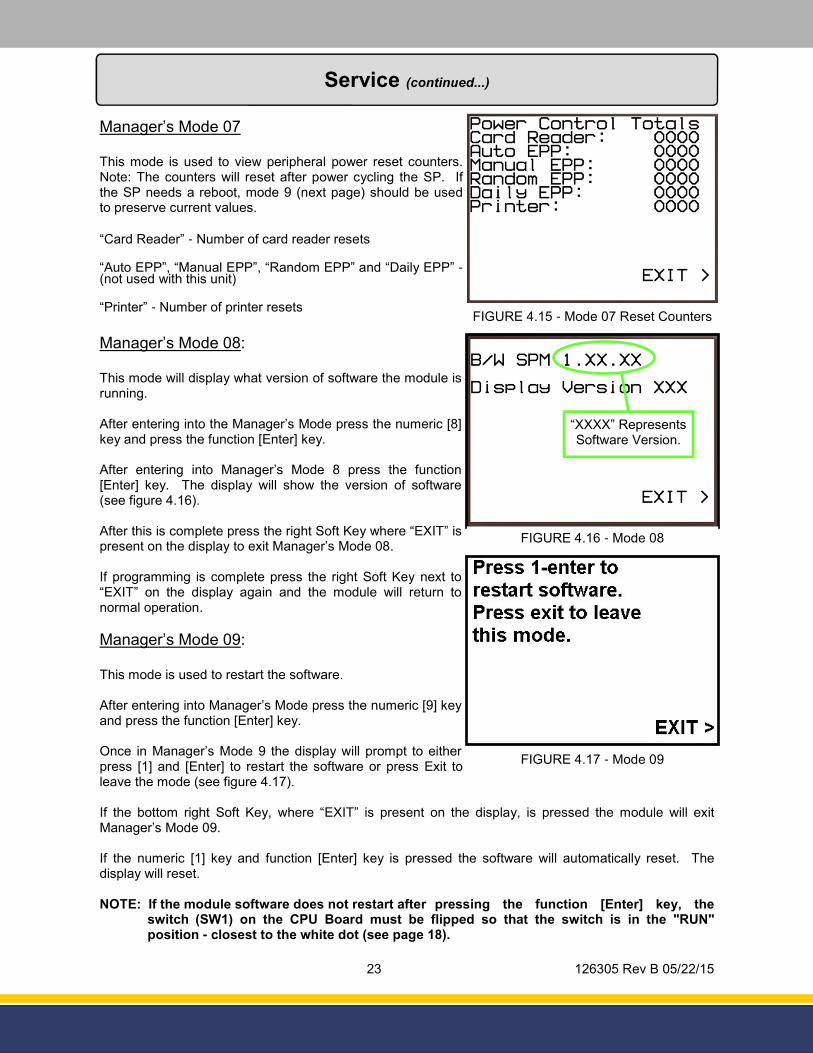
Manager’s Mode 07
This mode is used to view peripheral power reset counters. Note: The counters will reset after power cycling the SP. If the SP needs a reboot, mode 9 (next page) should be used to preserve current values.
“Card Reader” - Number of card reader resets
“Auto EPP”, “Manual EPP”, “Random EPP” and “Daily EPP” - (not used with this unit)
“Printer” - Number of printer resets
Manager’s Mode 08:
This mode will display what version of software the module is running.
After entering into the Manager’s Mode press the numeric [8] key and press the function [Enter] key.
After entering into Manager’s Mode 8 press the function [Enter] key. The display will show the version of software (see figure 4.16).
After this is complete press the right Soft Key where “EXIT” is present on the display to exit Manager’s Mode 08.
If programming is complete press the right Soft Key next to “EXIT” on the display again and the module will return to normal operation.
Manager’s Mode 09:
This mode is used to restart the software.
After entering into Manager’s Mode press the numeric [9] key and press the function [Enter] key.
Once in Manager’s Mode 9 the display will prompt to either press [1] and [Enter] to restart the software or press Exit to leave the mode (see figure 4.17).
If the bottom right Soft Key, where “EXIT” is present on the display, is pressed the module will exit Manager’s Mode 09.
If the numeric [1] key and function [Enter] key is pressed the software will automatically reset. The display will reset.
NOTE: If the module software does not restart after pressing the function [Enter] key, the switch (SW1) on the CPU Board must be flipped so that the switch is in the "RUN" position - closest to the white dot (see page 18).
FIGURE 4.16 - Mode 08
“XXXX” Represents Software Version.
FIGURE 4.15 - Mode 07 Reset Counters
FIGURE 4.17 - Mode 09
24 126305 Rev B 05/22/15
Service Service (continued...)
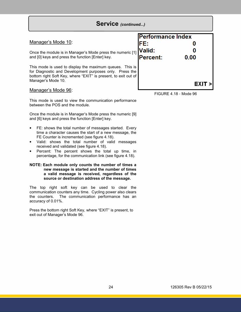
Manager’s Mode 10:
Once the module is in Manager’s Mode press the numeric [1] and [0] keys and press the function [Enter] key.
This mode is used to display the maximum queues. This is for Diagnostic and Development purposes only. Press the bottom right Soft Key, where “EXIT” is present, to exit out of Manager’s Mode 10.
Manager’s Mode 96:
This mode is used to view the communication performance between the POS and the module.
Once the module is in Manager’s Mode press the numeric [9] and [6] keys and press the function [Enter] key.
• FE: shows the total number of messages started. Every time a character causes the start of a new message, the FE Counter is incremented (see figure 4.18).
• Valid: shows the total number of valid messages received and validated (see figure 4.18).
• Percent: The percent shows the total up time, in percentage, for the communication link (see figure 4.18).
NOTE: Each module only counts the number of times a new message is started and the number of times a valid message is received, regardless of the source or destination address of the message.
The top right soft key can be used to clear the communication counters any time. Cycling power also clears the counters. The communication performance has an accuracy of 0.01%.
Press the bottom right Soft Key, where “EXIT” is present, to exit out of Manager’s Mode 96.
FIGURE 4.18 - Mode 96
25 126305 Rev B 05/22/15
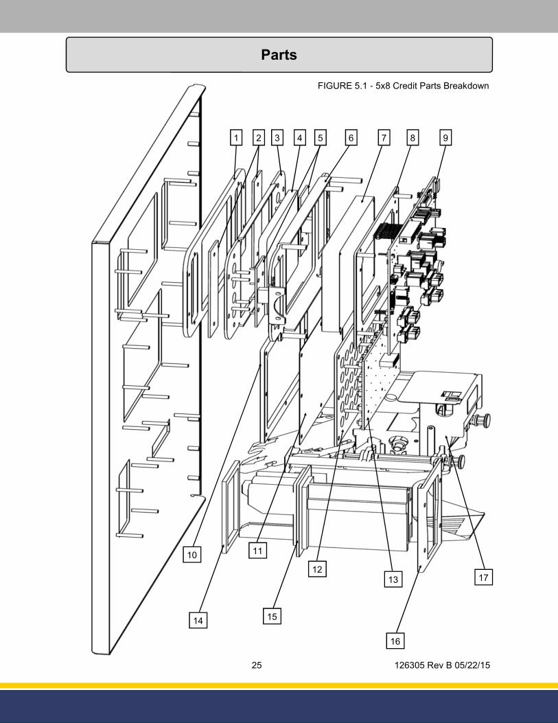
Parts
FIGURE 5.1 - 5x8 Credit Parts Breakdown
1 2 3 4 6 8 9
10
7
14
11
13
5
12
15
16
17
26 126305 Rev B 05/22/15
Parts
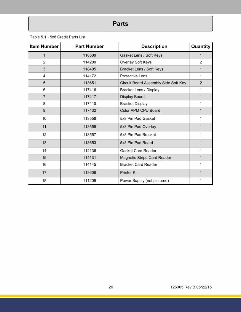
Table 5.1 - 5x8 Credit Parts List
Item Number Part Number Description Quantity
1 118509 Gasket Lens / Soft Keys 1
2 114209 Overlay Soft Keys 2
3 118495 Bracket Lens / Soft Keys 1
4 114172 Protective Lens 1
5 113651 Circuit Board Assembly Side Soft Key 2
6 117416 Bracket Lens / Display 1
7 117417 Display Board 1
8 117410 Bracket Display 1
9 117432 Color APM CPU Board 1
10 113558 5x8 Pin Pad Gasket 1
11 113559 5x8 Pin Pad Overlay 1
12 113557 5x8 Pin Pad Bracket 1
13 113653 5x8 Pin Pad Board 1
14 114136 Gasket Card Reader 1
15 114131 Magnetic Stripe Card Reader 1
16 114145 Bracket Card Reader 1
17 113606 Printer Kit 1
18 111209 Power Supply (not pictured) 1
27 126305 Rev B 05/22/15
Parts
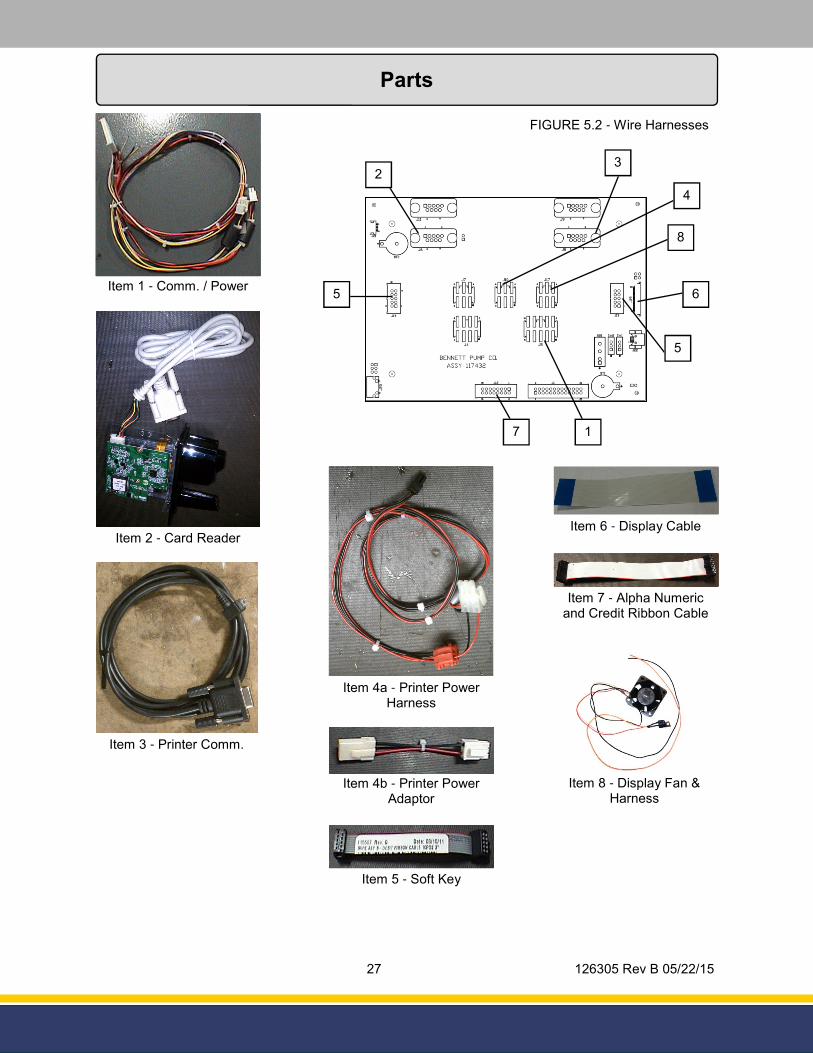
FIGURE 5.2 - Wire Harnesses
2
3
4
5
5
1
Item 2 - Card Reader
Item 4b - Printer Power Adaptor
Item 5 - Soft Key
Item 1 - Comm. / Power
Item 3 - Printer Comm.
Item 4a - Printer Power Harness
Item 6 - Display Cable
6
Item 7 - Alpha Numeric and Credit Ribbon Cable
7
Item 8 - Display Fan & Harness
8
28 126305 Rev B 05/22/15
Parts
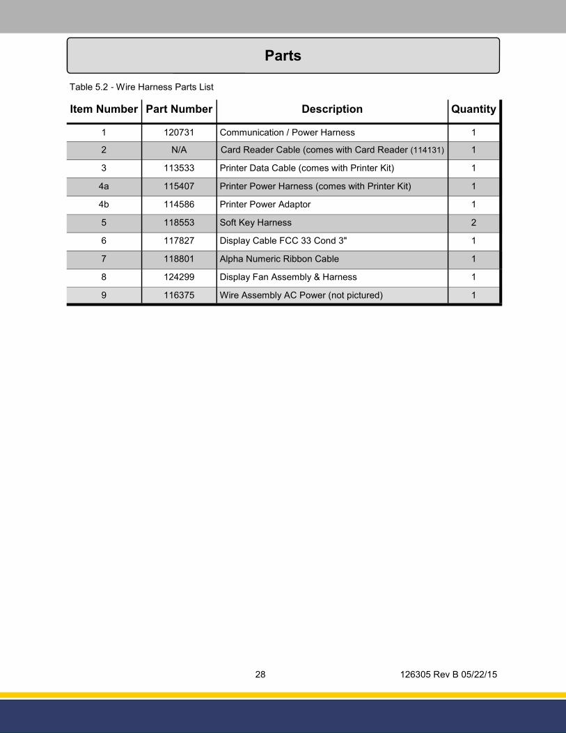
Item Number Part Number Description Quantity
1 120731 Communication / Power Harness 1
2 N/A Card Reader Cable (comes with Card Reader (114131) 1
3 113533 Printer Data Cable (comes with Printer Kit) 1
4a 115407 Printer Power Harness (comes with Printer Kit) 1
4b 114586 Printer Power Adaptor 1
5 118553 Soft Key Harness 2
6 117827 Display Cable FCC 33 Cond 3" 1
7 118801 Alpha Numeric Ribbon Cable 1
8 124299 Display Fan Assembly & Harness 1
9 116375 Wire Assembly AC Power (not pictured) 1
Table 5.2 - Wire Harness Parts List

29 126305 Rev B 05/22/15
Site Master Payment Terminal The payment terminal is warranted for parts, labor and travel for 12 months from date of installation or 18 months from date of original invoice, whichever comes first, except the receipt printer and driver board which is warranted for parts for ninety (90) days from the date of installation or 180 days from original invoice, whichever comes first.
Field Retrofit Card Readers, Payment Modules, Cash Acceptors, and all other field retrofit Accessories
The field retrofit assembly is warranted for parts only for 12 months from date of installation or 18 months from date of original invoice, whichever comes first, except the receipt printer and driver board which is warranted for parts for ninety (90) days from the date of installation or 180 days from original invoice, whichever comes first.
Consumable Items such as receipt paper are not warranted. The use of receipt paper not specified by Bennett will void the printer assembly warranty.
Model 515 Pump Controller, 621 Module, Fan Out Boxes
Warranty on parts, labor and travel is 12 months from the date of installation or 18 months from the date of original invoice, whichever comes first.
Software
Bennett Pump Company warrants Bennett products and software packages, whose operation is controlled by Bennett designed and developed software, shall be free of material defects and conform to current Bennett specifications for a period of ninety (90) days from the date of original invoice. Bennett shall use its best effort to correct such defects and to supply to purchaser at Bennett’s expense, a corrected version within a reasonable time after purchaser notifies Bennett in writing of any defects and provides the programs and instructions required to reproduce the claimed defect.
Warranty does not cover any modification to the program, the Bennett product, and/or connection to unapproved equipment made by any person or any defect caused by such modifications/connections.
Upgrade Kits
Bennett offers kits which are installed as an option to enhance operating features of an existing Bennett product are warranted for parts only for ninety (90) days from date of installation or 12 months from date of original invoice, whichever comes first. Upgrade Kit warranty applies to kit components only. Warranty status of the remainder of the product remains unchanged.
Spare Parts
For equipment under warranty: The warranty period for all spare parts replaced is the remainder of the original warranty. Spare Parts are warranted for the value of the parts only (no labor, mileage, or other charges).
For equipment not under warranty: The warranty period is 90 days from the date of invoice to the end user, or 12 months from the date of original invoice, whichever comes first. Spare Parts are warranted for the value of the parts only (no labor, mileage, or other charges).
General Exclusions
1. Warranty does not apply to any product which has been altered, subjected to unusual physical or electrical stress, an Act of God, damaged by accident, tampered with, or subjected to misuse or abuse including substituting parts or accessories from other manufacturers without the written consent of Bennett Pump Company. The above warranties shall not exist if the original identification marks have been removed or altered.
2. Bennett makes no warranty with respect to the Bennett equipment or Bennett’s performance of services under this agreement, express or implied, and Bennett hereby disclaims the implied warranties of merchantability and fitness for a particular purpose.
3. In no event shall Bennett be liable for any loss of profits, loss of use, interruption of business or indirect, special, incidental or consequential damages of any kind in connection with or arising out of the furnishing, performance, use or failure of the Bennett equipment, software or services acquired from Bennett, the distributor or the user, whether alleged as a breach of contract or tortuous conduct, including negligence. Bennett’s liability hereunder for damages shall not, in any event, exceed the amounts paid by the buyer to Bennett for equipment, software or services as to which the claim arose.
4. No action arising out of any claimed breach of the Warranty Agreement or transaction under this Warranty Agreement may be brought by either party more than two (2) years after the cause of action has accrued.
5. Use of non-Bennett replacement parts, unless specified by Bennett, will void the equipment warranty. 6. This warranty only applies to Bennett equipment installed in the United States of America and is non-transferable. 7. Failure to pay the Bennett invoice within stated invoice terms, covering the respective Bennett equipment purchased under this limited warranty
may, at Bennett’s discretion, void this limited product warranty.
THE FOREGOING WARRANTIES ARE IN LIEU OF ALL OTHER WARRANTIES EXPRESSED OR IMPLIED INCLUDING, WITHOUT LIMITATION, THE WARRANTY OF MERCHANTABILITY AND FITNESS FOR A PARTICULAR PURPOSE.
BENNETT PUMP COMPANY 1218 E. Pontaluna Road
Spring Lake, MI 49456
Tel: 231-798-1310 Fax: 231-799-6202
Bennett Limited Warranty for Products Installed in the United States - Site Master
Bennett Pump Company guarantees new Service Station Equipment manufactured by Bennett against defects in material or workmanship during the warranty period in accordance with the provisions stated below:
• The Site Audit Report issued with all equipment must be completed and returned at time of installation to Bennett Pump Company, Spring Lake,
MI to initiate warranty.
• Warranty service must be performed by the nearest Bennett Authorized Service Representative qualified to perform service on the defective
equipment. Only Authorized and Certified Service Representatives are allowed to perform warranty service. Use of service personnel other than qualified Bennett Service Representatives without prior approval by Bennett Pump Company will void payment of any warranty claims.
• Labor and travel costs incurred while servicing Bennett equipment will be paid at previously contracted rates subject to published standard repair
time allowances to qualified Bennett Service Representatives with travel cost limited to 200 miles. Travel cost shall be limited to 4 hours round trip.
• Bennett equipment has been installed according to the manufacturer’s instructions and diagrams.
• During the warranty period, Bennett Pump Company will, at its option, repair or replace defective parts returned to its factory, transportation
charges prepaid.
• The manufacturer reserves the right to make changes in the design or to make additions

30 126305 Rev B 05/22/15
Bennett 1218 E. Pontaluna Road Spring Lake, MI 49456 USA 800-235-7618 Outside USA 231-798-1310 [email protected]
www.bennettpump.com