Embed Size (px)
Citation preview
SITE /ROADWAY
OPTICALSYSTEMS
O p t i c a l S y s t e m sD E S I G N A N D A P P L I C A T I O N G U I D E
S I T E / R O A D W A Y

Table of Contents
Site Integration 2-3
Photometry Information 4-7
Distribution Types 8-10
Cutoff Description 11
Isofootcandle Plots 12-13
Application of Patterns 14
Modifiers 15
Optical Systems Design 16-17
Reflector Mechanical Design 18
Kim Systems Overview 19-20
Horizontal Lamp Luminaires 22
Vertical Lamp Luminaires 23
Horizontal Lamp 25-30
Two-Tier Vertical Lamp 31-36
Single-Tier Vertical Lamp 37-40
Applications Assistance 41
Footnotes 41
SITE / AREAPARKING STRUCTURE
ROADWAYARCHITECTURAL FLOOD
ACCENTLANDSCAPE
MAILING ADDRESS:P.O. BOX 60080
CITY OF INDUSTRY, CA 91716-0080
BUSINESS ADDRESS:16555 EAST GALE AVENUE
CITY OF INDUSTRY, CA 91745U.S.A.
PHONE 626 / 968 - 5666FAX 626 / 369 - 2695
ENTIRE CONTENTS© COPYRIGHT 1999 KIM LIGHTING, INC.
ALL RIGHTS RESERVEDREPRODUCTION IN WHOLE OR IN PART
WITHOUT PERMISSION IS STRICTLY PROHIBITED.
www.kimlighting.com
Audited to ISO9001 Standards
RvA Councilfor Accreditation
Printed in U.S.A.5502599253
Version 1.01 (6/06)
IntroductionThe design of Site/Roadway Lighting requiresan understanding of the unique informationused to represent elements of opticalperformance. This catalog includesdescriptions of the standards used to defineproduct characteristics and predict the appliedperformance of outdoor area luminaires.
Kim's unique approach to optical systemsdesign and reflector fabrication follows thesefundamental definitions. The descriptions offerinsight into the features and benefits of Kim'sinnovative optical systems.
The heart of this catalog is the Optical SystemsSpecifications. Used in Kim Site/Roadwayproducts, these reflector systems are the directresult of 70 years dedicated to providingsuperior performance in outdoor lighting.
Site / Roadway
Optical Systems

KKIIMM LIGHTING 11
More than the sum of its parts, each Kim reflector is acomposite of materials, technology, research, andcontinuous development. Designed to; efficientlydistribute light into desired luminous zones, control glare,and compliment Kim aesthetic designs, these simplelooking devices are the heart of a superior lighting system.
NeighboringResidential
Property
9999 9999 99 99 99 99
99
99
Shop99
99
Shop
KKIIMM LIGHTING 33
Site Integration
Design, Focused on Applied Performance
22 KKIIMM LIGHTING
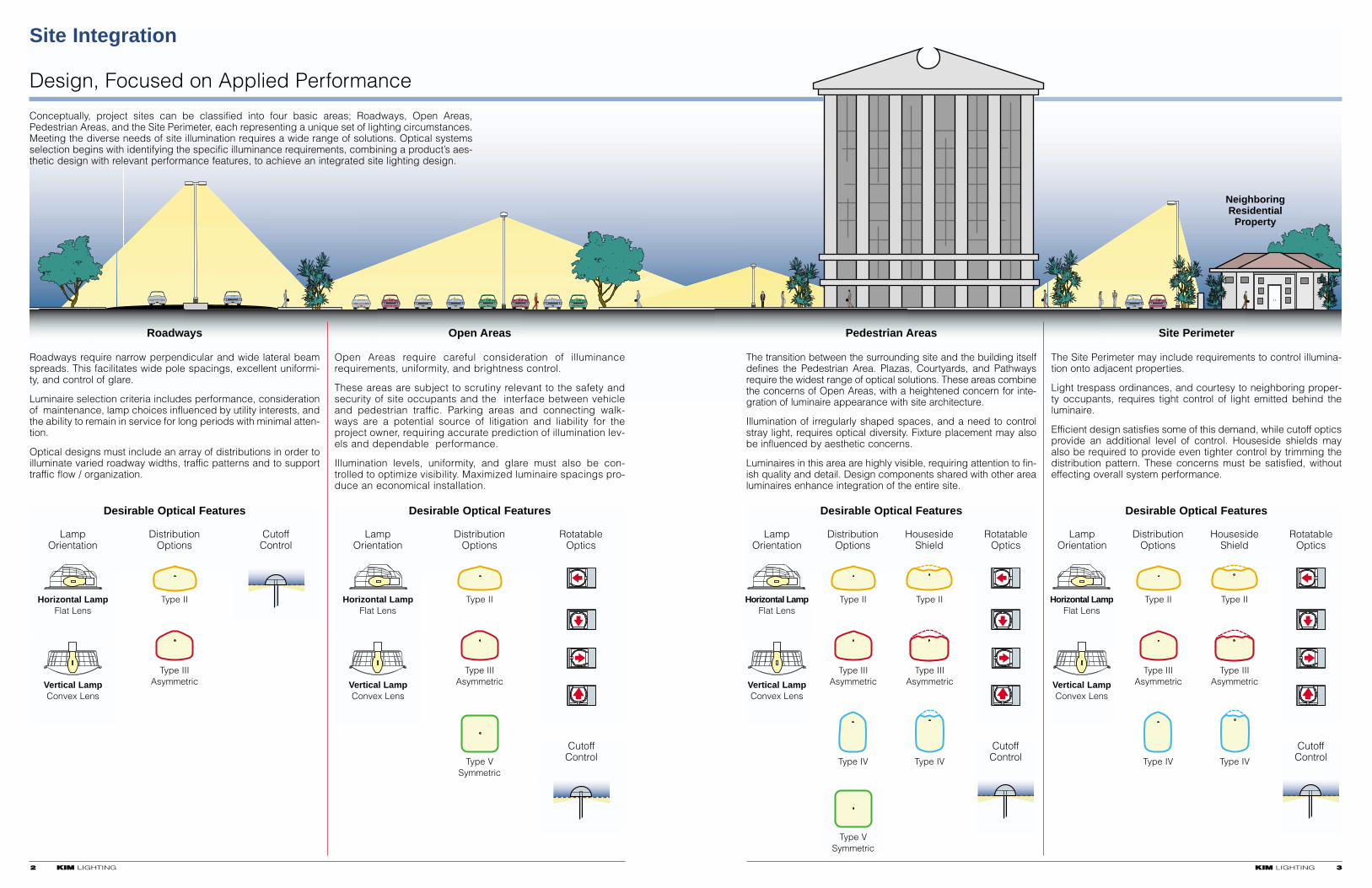
Conceptually, project sites can be classified into four basic areas; Roadways, Open Areas,Pedestrian Areas, and the Site Perimeter, each representing a unique set of lighting circumstances.Meeting the diverse needs of site illumination requires a wide range of solutions. Optical systemsselection begins with identifying the specific illuminance requirements, combining a product’s aes-thetic design with relevant performance features, to achieve an integrated site lighting design.
Roadways require narrow perpendicular and wide lateral beamspreads. This facilitates wide pole spacings, excellent uniformi-ty, and control of glare.
Luminaire selection criteria includes performance, considerationof maintenance, lamp choices influenced by utility interests, andthe ability to remain in service for long periods with minimal atten-tion.
Optical designs must include an array of distributions in order toilluminate varied roadway widths, traffic patterns and to supporttraffic flow / organization.
Open Areas require careful consideration of illuminancerequirements, uniformity, and brightness control.
These areas are subject to scrutiny relevant to the safety andsecurity of site occupants and the interface between vehicleand pedestrian traffic. Parking areas and connecting walk-ways are a potential source of litigation and liability for theproject owner, requiring accurate prediction of illumination lev-els and dependable performance.
Illumination levels, uniformity, and glare must also be con-trolled to optimize visibility. Maximized luminaire spacings pro-duce an economical installation.
The transition between the surrounding site and the building itselfdefines the Pedestrian Area. Plazas, Courtyards, and Pathwaysrequire the widest range of optical solutions. These areas combinethe concerns of Open Areas, with a heightened concern for inte-gration of luminaire appearance with site architecture.
Illumination of irregularly shaped spaces, and a need to controlstray light, requires optical diversity. Fixture placement may alsobe influenced by aesthetic concerns.
Luminaires in this area are highly visible, requiring attention to fin-ish quality and detail. Design components shared with other arealuminaires enhance integration of the entire site.
The Site Perimeter may include requirements to control illumina-tion onto adjacent properties.
Light trespass ordinances, and courtesy to neighboring proper-ty occupants, requires tight control of light emitted behind theluminaire.
Efficient design satisfies some of this demand, while cutoff opticsprovide an additional level of control. Houseside shields mayalso be required to provide even tighter control by trimming thedistribution pattern. These concerns must be satisfied, withouteffecting overall system performance.
Roadways Open Areas Pedestrian Areas Site Perimeter
Desirable Optical Features Desirable Optical Features Desirable Optical Features Desirable Optical Features
Lamp Distribution RotatableOrientation Options Optics
Lamp Distribution Houseside RotatableOrientation Options Shield Optics
Lamp Distribution Houseside RotatableOrientation Options Shield Optics
Type II Type II Type II
Type IIIAsymmetric
Type IIIAsymmetric
Type IIIAsymmetric
Type VSymmetric
Type IV
Type VSymmetric
Type IV
Lamp Distribution CutoffOrientation Options Control
Horizontal LampFlat Lens
Type II
Vertical LampConvex Lens
Type IIIAsymmetric
CutoffControl
CutoffControl
CutoffControl
Type II
Type IIIAsymmetric
Type IV
Type II
Type IIIAsymmetric
Type IV
Horizontal LampFlat Lens
Vertical LampConvex Lens
Horizontal LampFlat Lens
Vertical LampConvex Lens
Horizontal LampFlat Lens
Vertical LampConvex Lens
(34.42')
REPORT NUMBER: ITL44999
DATE: 02/02/99
PREPARED FOR: KIM LIGHTING INC.
CATALOG NUMBER: AR
LUMINAIRE: DIE CAST HOUSING, MULTI-FACETED PEENED
REFLECTOR ABOVE LAMP, MULTI-FACETED SPECULAR
REFLECTOR, DIFFUSE FORMER
LAMP: (1) 150W CLEAR E-23 H.P.S.
REPORT BASED ON 16000 LUMEN LAMP.
MAXIMUM PLANE AND CONE PLOTS OF CANDELAREPORT NUMBER: ITL44999
DATE: 02/02/99
PREPARED FOR: KIM LIGHTING INC.
CANDELA TABULATION
180.0
155.0
125.0
115.0
105.0
95.0
85.0
75.0
66.0
65.0
55.0
45.0
35.0
25.0
15.0
5.0
0.0
0.0
0.
0.
0.
0.
4.
7.
18.
327.
728.
782.
1674.
2219.
2110.
982.
582.
491.
363.
15.0
0.
0.
0.
0.
7.
9.
24.
491.
746.
810.
1983.
2192.
2165.
964.
600.
491.
363.
35.0
0.
0.
0.
0.
9.
15.
27.
700.
2492.
2465.
2610.
2310.
2092.
1137.
664.
491.
363.
55.0
0.
0.
5.
9.
12.
15.
36.
1701.
4011.
4339.
4066.
2392.
2092.
1674.
655.
491.
363.
71.0
0.
0.
0.
0.
9.
15.
36.
3893.
8595.
8295.
7104.
2301.
2056.
1946.
582.
455.
363.
75.0
0.
0.
5.
9.
15.
18.
45.
3993.
8232.
8141.
6631.
2228.
2047.
1956.
600.
464.
363.
95.0
0.
0.
9.
12.
15.
18.
36.
810.
3183.
3429.
3029.
1974.
1956.
1956.
746.
418.
363.
115.0
0.
0.
9.
12.
15.
18.
45.
500.
1783.
1810.
2001.
1865.
1910.
1874.
1101.
364.
363.
135.0
0.
0.
9.
12.
15.
18.
55.
300.
1674.
1737.
2010.
1865.
1846.
1792.
1264.
327.
363.
155.0
0.
0.
0.
0.
9.
12.
45.
518.
1437.
1483.
1655.
1719.
1774.
1728.
1392.
318.
363.
180.0
0.
0.
0.
0.
12.
12.
36.
382.
1037.
1110.
1492.
1674.
1746.
1674.
1346.
309.
363.
VERTICAL ANGLE
LATERAL ANGLE
HOUSE SIDESTREET SIDE
8400
5600
2800
2800
5600
8400
Maximum candela in vertical planeestablishes angle of cone for
lateral candela plot
Maximum candela angle in lateralplane establishes angle for
vertical candela plot
2800
5600
8400
House Side
Street Side
0° Lateral
Lateral candela plotis traced on the
surface of a cone
The vertical candelaplot is traced on a
vertical plane
Vert
ica
l Pla
ne
30°
60°
66° Vertical
Reference Line
71° Lateral71° Lateral
(71° Lateral)
Reference Line
8595 candela
House Side
Street Side
D VA (66˚ Vertical)
0,0
a (14.0')
LAb (31.44')
10.23' (.73 Mounting Heights)
fc = (8595 / 34.422) x .407 = 2.95 fc
Footcandles atMaximum Candela = 2.95
Maximum Candela Angle
Maximum Candela Angle
Maximum Candela Angle
Maximum candela corresponds to apoint @ 71° Lateral x 66° Vertical
from the reference line and 0° nadir
0° Vertical (nadir)
House Side
Street Side
Maximum Candela
figure 5.1
figure 5.2
figure 4.1
figure 4.2
180°
0°
180°
0°
90°
90°
HouseSide
StreetSide
LateralAngle
VerticalAngle
90°
Footcandles (fc) = [(Candela @ VA by LA) / D2] x cosine VA
0°
71° Lateral Angle66° Vertical Angle
29.73' (2.12 Mounting Heights)
KKIIMM LIGHTING 55
Photometry Information
Basic Language and Presentation
44 KKIIMM LIGHTING
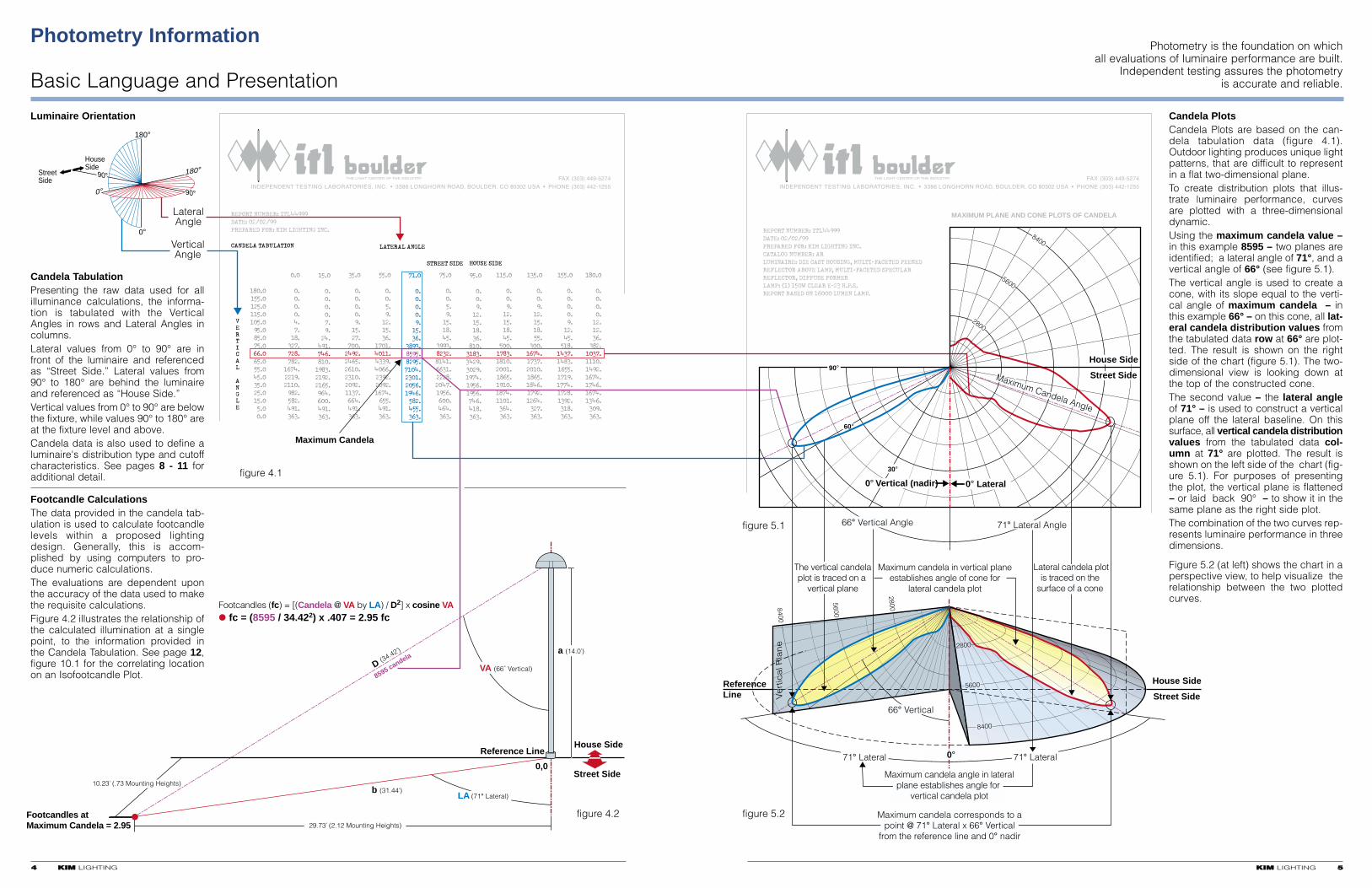
Candela TabulationPresenting the raw data used for allilluminance calculations, the informa-tion is tabulated with the VerticalAngles in rows and Lateral Angles incolumns. Lateral values from 0° to 90° are infront of the luminaire and referencedas “Street Side.” Lateral values from90° to 180° are behind the luminaireand referenced as “House Side.”Vertical values from 0° to 90° are belowthe fixture, while values 90° to 180° areat the fixture level and above.Candela data is also used to define aluminaire's distribution type and cutoffcharacteristics. See pages 8 - 11 foradditional detail.
Luminaire Orientation
Footcandle CalculationsThe data provided in the candela tab-ulation is used to calculate footcandlelevels within a proposed lightingdesign. Generally, this is accom-plished by using computers to pro-duce numeric calculations. The evaluations are dependent uponthe accuracy of the data used to makethe requisite calculations.Figure 4.2 illustrates the relationship ofthe calculated illumination at a singlepoint, to the information provided inthe Candela Tabulation. See page 12,figure 10.1 for the correlating locationon an Isofootcandle Plot.
Candela PlotsCandela Plots are based on the can-dela tabulation data (figure 4.1).Outdoor lighting produces unique lightpatterns, that are difficult to representin a flat two-dimensional plane. To create distribution plots that illus-trate luminaire performance, curvesare plotted with a three-dimensionaldynamic.Using the maximum candela value –in this example 8595 – two planes areidentified; a lateral angle of 71°, and avertical angle of 66° (see figure 5.1). The vertical angle is used to create acone, with its slope equal to the verti-cal angle of maximum candela – inthis example 66° – on this cone, all lat-eral candela distribution values fromthe tabulated data row at 66° are plot-ted. The result is shown on the rightside of the chart (figure 5.1). The two-dimensional view is looking down atthe top of the constructed cone.The second value – the lateral angleof 71° – is used to construct a verticalplane off the lateral baseline. On thissurface, all vertical candela distributionvalues from the tabulated data col-umn at 71° are plotted. The result isshown on the left side of the chart (fig-ure 5.1). For purposes of presentingthe plot, the vertical plane is flattened– or laid back 90° – to show it in thesame plane as the right side plot.The combination of the two curves rep-resents luminaire performance in threedimensions.
Figure 5.2 (at left) shows the chart in aperspective view, to help visualize therelationship between the two plottedcurves.
Photometry is the foundation on whichall evaluations of luminaire performance are built.
Independent testing assures the photometryis accurate and reliable.
Photometry Testing
Variables Affecting Accurate Information
66 KKIIMM LIGHTING
The Importance of AccuracySite/Area Illumination design isconcerned with relatively largelamp sources, applied over largeareas. Visual acuity is greatlyinfluenced by control of glare anduniformity. In this, subtle varia-tions in the performance of lumi-naires have a dramatic effect onthe illuminated field. The only wayto accurately predict the perform-ance of a proposed design, isthrough the application of accu-rate performance data.
Comparing PerformanceIn addition to accurately predict-ing the performance of a singlesystem, comparisons of perform-ance between two systems, pro-duced by disparate providers,can only be accomplished if thedata provided by both is acquiredusing some form of mutuallyaccepted standard. Ideally, thiswould include an independentsource of testing, unbiased, utiliz-ing industry established stan-dards.True comparisons of differentoptical systems can only beaccomplished when the methodof testing is the same for bothsystems.
Assumptions andCompromisesTo save money, many manufac-turers utilize methods that com-promise accuracy under theassumption that small variancesare not important. Just how farthese assumptions are carried isnever clearly defined and variesfrom one provider to another. Thismakes it very difficult to deter-mine where actual test informa-tion and the compromises beginand end. To make the most qualified,informed decisions, accuracyand dependability of informationis vital. Compromises andassumptions have no place in theraw data being used to makeselections.
ProratingProrating is a common practice inthe representation of luminaireperformance. It is based onapplying multipliers, based onraw lamp lumens, to a known testresult. For example; A testaccomplished on a system with a10,000 lumen lamp, is pro-ratedto represent a system using a5,000 lumen lamp, by simplyapplying a .5 multiplier to the testdata on the base luminaire. This wrongly assumes that all otherfactors are exactly equal, that theonly variation is raw lumens.With High Intensity Discharge(H.I.D.) sources, every lamp isdifferent, based on:• Arc Tube Shape (Metal Halide
or High Pressure Sodium)• Arc Tube Size• Envelope size (ED-17 through
BT-56)• Base Size (medium or mogul)• Envelope shape• Intended operating position
(vertical, horizontal or universal)• Position of the arc tube within
the envelope• Whether or not the socket
design locks the lamp into agiven position (pin orientation).
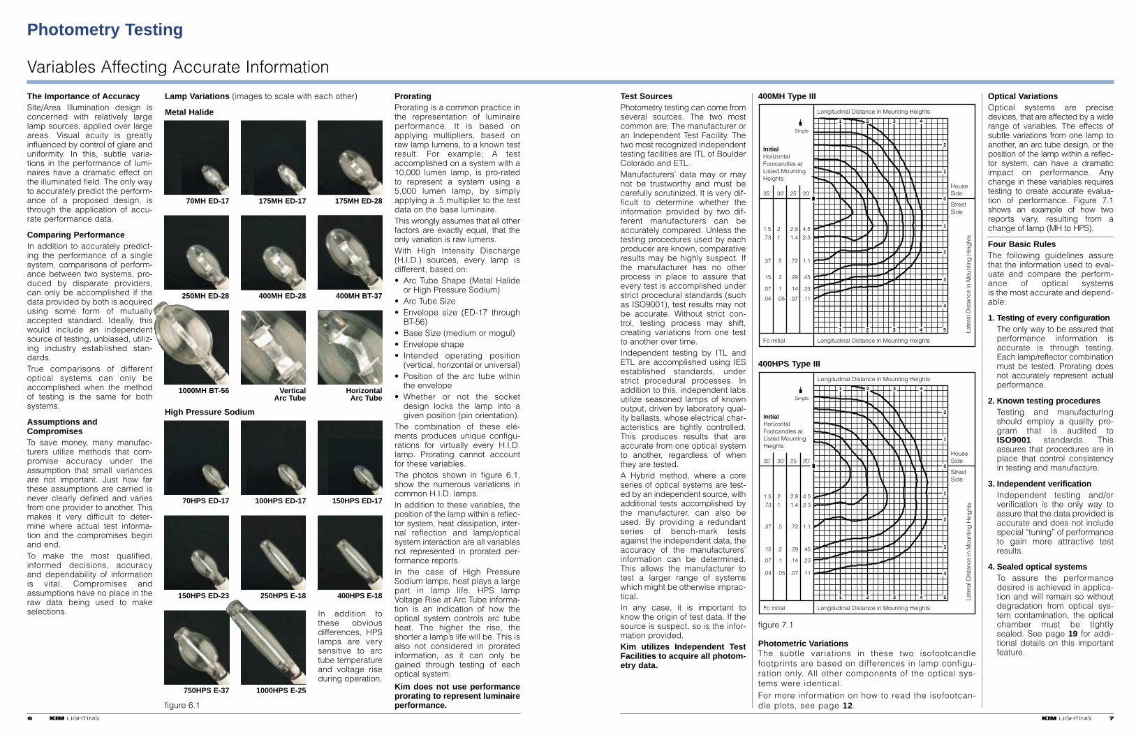
The combination of these ele-ments produces unique configu-rations for virtually every H.I.D.lamp. Prorating cannot accountfor these variables.The photos shown in figure 6.1,show the numerous variations incommon H.I.D. lamps. In addition to these variables, theposition of the lamp within a reflec-tor system, heat dissipation, inter-nal reflection and lamp/opticalsystem interaction are all variablesnot represented in prorated per-formance reports.In the case of High PressureSodium lamps, heat plays a largepart in lamp life. HPS lampVoltage Rise at Arc Tube informa-tion is an indication of how theoptical system controls arc tubeheat. The higher the rise, theshorter a lamp’s life will be. This isalso not considered in proratedinformation, as it can only begained through testing of eachoptical system.
Kim does not use performanceprorating to represent luminaireperformance.
Lamp Variations (images to scale with each other)
Metal Halide
figure 6.1
High Pressure Sodium
70MH ED-17 175MH ED-17 175MH ED-28
In addition tothese obviousdifferences, HPSlamps are verysensitive to arctube temperatureand voltage riseduring operation.
250MH ED-28 400MH ED-28 400MH BT-37
1000MH BT-56 Vertical HorizontalArc Tube Arc Tube
70HPS ED-17 100HPS ED-17 150HPS ED-17
150HPS ED-23 250HPS E-18 400HPS E-18
750HPS E-37 1000HPS E-25
KKIIMM LIGHTING 77
Test SourcesPhotometry testing can come fromseveral sources. The two mostcommon are; The manufacturer oran Independent Test Facility. Thetwo most recognized independenttesting facilities are ITL of BoulderColorado and ETL. Manufacturers’ data may or maynot be trustworthy and must becarefully scrutinized. It is very dif-ficult to determine whether theinformation provided by two dif-ferent manufacturers can beaccurately compared. Unless thetesting procedures used by eachproducer are known, comparativeresults may be highly suspect. Ifthe manufacturer has no otherprocess in place to assure thatevery test is accomplished understrict procedural standards (suchas ISO9001), test results may notbe accurate. Without strict con-trol, testing process may shift,creating variations from one testto another over time.Independent testing by ITL andETL are accomplished using IESestablished standards, understrict procedural processes. Inaddition to this, independent labsutilize seasoned lamps of knownoutput, driven by laboratory qual-ity ballasts, whose electrical char-acteristics are tightly controlled.This produces results that areaccurate from one optical systemto another, regardless of whenthey are tested.A Hybrid method, where a coreseries of optical systems are test-ed by an independent source, withadditional tests accomplished bythe manufacturer, can also beused. By providing a redundantseries of bench-mark testsagainst the independent data, theaccuracy of the manufacturers’information can be determined.This allows the manufacturer totest a larger range of systemswhich might be otherwise imprac-tical.In any case, it is important toknow the origin of test data. If thesource is suspect, so is the infor-mation provided.Kim utilizes Independent TestFacilities to acquire all photom-etry data.
Optical VariationsOptical systems are precisedevices, that are affected by a widerange of variables. The effects ofsubtle variations from one lamp toanother, an arc tube design, or theposition of the lamp within a reflec-tor system, can have a dramaticimpact on performance. Anychange in these variables requirestesting to create accurate evalua-tion of performance. Figure 7.1shows an example of how tworeports vary, resulting from achange of lamp (MH to HPS).
Four Basic RulesThe following guidelines assurethat the information used to eval-uate and compare the perform-ance of optical systems is the most accurate and depend-able:
1. Testing of every configurationThe only way to be assured thatperformance information isaccurate is through testing.Each lamp/reflector combinationmust be tested. Prorating doesnot accurately represent actualperformance.
2. Known testing proceduresTesting and manufacturingshould employ a quality pro-gram that is audited toISO9001 standards. Thisassures that procedures are inplace that control consistencyin testing and manufacture.
3. Independent verificationIndependent testing and/orverification is the only way toassure that the data provided isaccurate and does not includespecial “tuning” of performanceto gain more attractive testresults.
4. Sealed optical systemsTo assure the performancedesired is achieved in applica-tion and will remain so withoutdegradation from optical sys-tem contamination, the opticalchamber must be tightlysealed. See page 19 for addi-tional details on this importantfeature.
Photometric VariationsThe subtle variations in these two isofootcandlefootprints are based on differences in lamp configu-ration only. All other components of the optical sys-tems were identical.For more information on how to read the isofootcan-dle plots, see page 12.
figure 7.1
400MH Type III
400HPS Type III
35' 30' 25' 20'
InitialHorizontalFootcandles atListed MountingHeights
1.5
.73
.37
.15
.07
.04
2
1
.5
.2
.1
.05
2.9
1.4
.72
.29
.14
.07
4.5
2.3
1.1
.45
.23
.11
Single
Fc initial
HouseSide
StreetSide
Longitudinal Distance in Mounting Heights
Late
ral D
ista
nce
in M
ount
ing
Hei
ght
s
Longitudinal Distance in Mounting Heights
1
1
2
2
3
3
4
4
2
0
1
1
2
3
4
5
REPORT NUMBER: ITL44933
DATE: 02/02/99
PREPARED FOR: KIM LIGHTING INC.
CANDELA TABULATION
180.0
155.0
125.0
115.0
105.0
95.0
85.0
75.0
66.0
65.0
55.0
45.0
35.0
25.0
15.0
5.0
0.0
0.0
0.
0.
0.
0.
4.
7.
18.
327.
728.
782.
1674.
2219.
2110.
982.
582.
491.
363.
15.0
0.
0.
0.
0.
7.
9.
24.
491.
746.
810.
1983.
2192.
2165.
964.
600.
491.
363.
35.0
0.
0.
0.
0.
9.
15.
27.
700.
2492.
2465.
2610.
2310.
2092.
1137.
664.
491.
363.
55.0
0.
0.
5.
9.
12.
15.
36.
1701.
4011.
4339.
4066.
2392.
2092.
1674.
655.
491.
363.
71.0
0.
0.
0.
0.
9.
15.
36.
4325.
8595.
6913.
4325.
1946.
582.
455.
363.
75.0
0.
0.
5.
9.
15.
18.
45.
4325.
8232.
8141.
6631.
2228.
2047.
1956.
600.
464.
363.
90.0
0.
0.
9.
12.
15.
18.
36.
1256.
4302.
4466.
3250.
1974.
1956.
1956.
746.
418.
363.
115.0
0.
0.
9.
12.
15.
18.
45.
500.
1783.
1810.
2001.
1865.
1910.
1874.
1101.
364.
363.
135.0
0.
0.
9.
12.
15.
18.
55.
300.
1674.
1737.
2010.
1865.
1846.
1792.
1264.
327.
363.
155.0
0.
0.
0.
0.
9.
12.
45.
518.
1437.
1483.
1655.
1719.
1774.
1728.
1392.
318.
363.
180.0
0.
0.
0.
0.
12.
12.
36.
382.
1037.
1110.
1492.
1674.
1746.
1674.
1346.
309.
363.
VERTICAL ANGLE
LATERAL ANGLE
HOUSE SIDESTREET SIDE
House Side
Street Side
MH
1.75 MH
2.75 MH
2.25 MH3.75 MH6.0 MH
Reference Line
Type II
Type III
Type IV
SHORT RANGEMEDIUM RANGELONG RANGE
Point ofMaximum Candela
Outline of10% Maximum candela
1.0 MH
VERY SHORT RANGE
Minor deviation not considered
3
50% MaximumCandela Trace
figure 6.1
figure 6.2
KKIIMM LIGHTING 9988 KKIIMM LIGHTING
Distribution Types
Definitions and Methodology
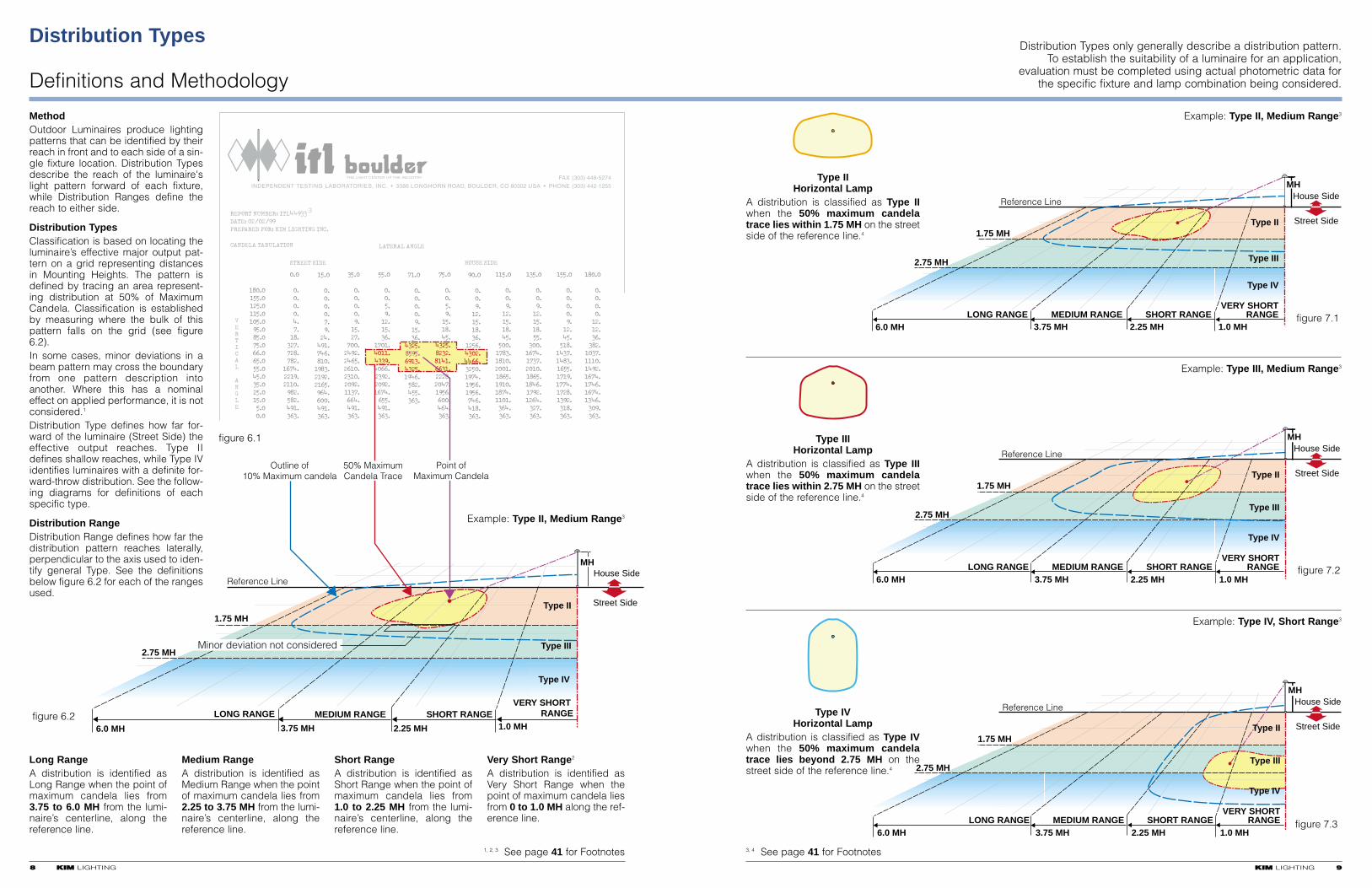
MethodOutdoor Luminaires produce lightingpatterns that can be identified by theirreach in front and to each side of a sin-gle fixture location. Distribution Typesdescribe the reach of the luminaire'slight pattern forward of each fixture,while Distribution Ranges define thereach to either side.
Distribution TypesClassification is based on locating theluminaire’s effective major output pat-tern on a grid representing distancesin Mounting Heights. The pattern isdefined by tracing an area represent-ing distribution at 50% of MaximumCandela. Classification is establishedby measuring where the bulk of thispattern falls on the grid (see figure6.2).In some cases, minor deviations in abeam pattern may cross the boundaryfrom one pattern description intoanother. Where this has a nominaleffect on applied performance, it is notconsidered.1
Distribution Type defines how far for-ward of the luminaire (Street Side) theeffective output reaches. Type IIdefines shallow reaches, while Type IVidentifies luminaires with a definite for-ward-throw distribution. See the follow-ing diagrams for definitions of eachspecific type.
Distribution RangeDistribution Range defines how far thedistribution pattern reaches laterally,perpendicular to the axis used to iden-tify general Type. See the definitionsbelow figure 6.2 for each of the rangesused.
Long RangeA distribution is identified asLong Range when the point ofmaximum candela lies from3.75 to 6.0 MH from the lumi-naire’s centerline, along thereference line.
Medium RangeA distribution is identified asMedium Range when the pointof maximum candela lies from2.25 to 3.75 MH from the lumi-naire’s centerline, along thereference line.
Short RangeA distribution is identified asShort Range when the point ofmaximum candela lies from1.0 to 2.25 MH from the lumi-naire’s centerline, along thereference line.
Very Short Range2
A distribution is identified asVery Short Range when thepoint of maximum candela liesfrom 0 to 1.0 MH along the ref-erence line.
1, 2, 3 See page 41 for Footnotes
Example: Type II, Medium Range3
Distribution Types only generally describe a distribution pattern.To establish the suitability of a luminaire for an application,
evaluation must be completed using actual photometric data forthe specific fixture and lamp combination being considered.
Type IIHorizontal Lamp
A distribution is classified as Type IIwhen the 50% maximum candelatrace lies within 1.75 MH on the streetside of the reference line.4
Type IIIHorizontal Lamp
A distribution is classified as Type IIIwhen the 50% maximum candelatrace lies within 2.75 MH on the streetside of the reference line.4
Type IVHorizontal Lamp
A distribution is classified as Type IVwhen the 50% maximum candelatrace lies beyond 2.75 MH on thestreet side of the reference line.4
Street Side1.75 MH
2.75 MH
2.25 MH3.75 MH6.0 MH
Reference LineHouse Side
MH
1.0 MHfigure 7.1
Type II
Type III
Type IV
SHORT RANGEMEDIUM RANGELONG RANGEVERY SHORT
RANGE
Street Side1.75 MH
2.75 MH
2.25 MH3.75 MH6.0 MH
Reference Line
Type III
Type IV
SHORT RANGEMEDIUM RANGELONG RANGE
House SideMH
1.0 MH
VERY SHORTRANGE figure 7.2
Type II
Street Side1.75 MH
2.75 MH
2.25 MH3.75 MH6.0 MH
Reference Line
Type II
Type III
Type IV
SHORT RANGEMEDIUM RANGELONG RANGE
House SideMH
1.0 MH
VERY SHORTRANGE figure 7.3
Example: Type II, Medium Range3
Example: Type III, Medium Range3
Example: Type IV, Short Range3
3, 4 See page 41 for Footnotes
House Side
Street Side
Reference Line
1.0 MH
MH
1.0 MH
1.0 MH
figure 8.1
2.25 MH
Reference Line
NARROWWIDE
MH
1.0 MH
figure 8.2
House Side
Street Side
2.25 MH
Reference Line
NARROWWIDE
1.0 MH
1.0 MHMH
figure 8.3
House Side
Street Side
Distribution Types
Definitions
1100 KKIIMM LIGHTING
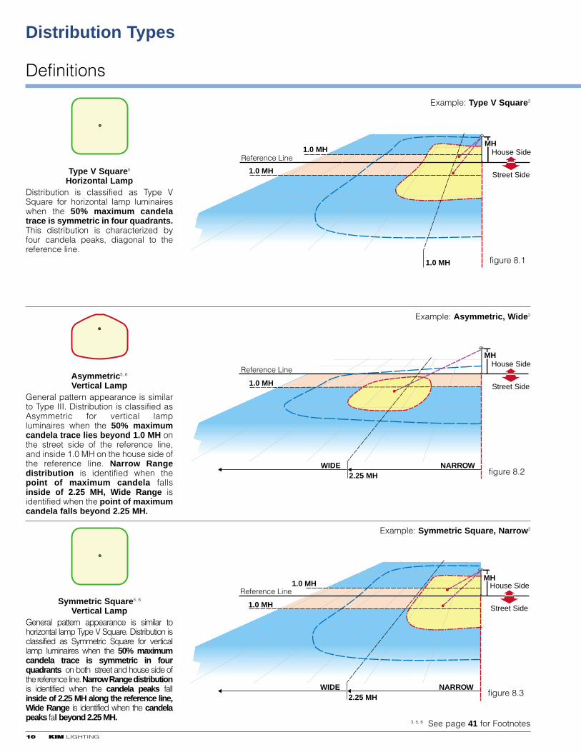
Type V Square5
Horizontal LampDistribution is classified as Type VSquare for horizontal lamp luminaireswhen the 50% maximum candelatrace is symmetric in four quadrants.This distribution is characterized byfour candela peaks, diagonal to thereference line.
Asymmetric5, 6
Vertical LampGeneral pattern appearance is similarto Type III. Distribution is classified asAsymmetric for vertical lampluminaires when the 50% maximumcandela trace lies beyond 1.0 MH onthe street side of the reference line,and inside 1.0 MH on the house side ofthe reference line. Narrow Rangedistribution is identified when thepoint of maximum candela fallsinside of 2.25 MH, Wide Range isidentified when the point of maximumcandela falls beyond 2.25 MH.
Symmetric Square5, 6
Vertical LampGeneral pattern appearance is similar tohorizontal lamp Type V Square. Distribution isclassified as Symmetric Square for verticallamp luminaires when the 50% maximumcandela trace is symmetric in fourquadrants on both street and house side ofthe reference line. Narrow Range distributionis identified when the candela peaks fallinside of 2.25 MH along the reference line,Wide Range is identified when the candelapeaks fall beyond 2.25 MH.
Example: Type V Square3
Example: Asymmetric, Wide3
Example: Symmetric Square, Narrow3
3, 5, 6 See page 41 for Footnotes
REPORT NUMBER: ITL44999
DATE: 02/02/99
PREPARED FOR: KIM LIGHTING INC.
CANDELA TABULATION
180.0
155.0
125.0
115.0
105.0
90.0
80.0
75.0
66.0
65.0
55.0
45.0
35.0
25.0
15.0
5.0
0.0
0.0
0.
0.
0.
0.
4.
7.
18.
327.
728.
782.
1674.
2219.
2110.
982.
582.
491.
363.
15.0
0.
0.
0.
0.
7.
9.
24.
491.
746.
810.
1983.
2192.
2165.
964.
600.
491.
363.
35.0
0.
0.
0.
0.
9.
15.
27.
700.
2492.
2465.
2610.
2310.
2092.
1137.
664.
491.
363.
55.0
0.
0.
5.
9.
12.
15.
36.
1701.
4011.
4339.
4066.
2392.
2092.
1674.
655.
491.
363.
71.0
0.
0.
0.
0.
9.
15.
36.
4325.
8595.
6913.
4325.
1946.
582.
455.
363.
75.0
0.
0.
5.Ł
9.Ł
15.
18.
45.
4325.
8232.
8141.
6631.
2228.
2047.
1956.
600.
464.
363.
90.0
0.
0.
9.
12.
15.
18.
36.
1256.
4302.
4466.
3250.
1974.
1956.
1956.
746.
418.
363.
115.0
0.
0.
9.
12.
15.
18.
45.
500.
1783.
1810.
2001.
1865.
1910.
1874.
1101.
364.
363.
135.0
0.
0.
9.
12.
15.
18.
55.
300.
1674.
1737.
2010.
1865.
1846.
1792.
1264.
327.
363.
155.0
0.
0.
0.
0.
9.
12.
45.
518.
1437.
1483.
1655.
1719.
1774.
1728.
1392.
318.
363.
180.0
0.
0.
0.
0.
12.
12.
36.
382.
1037.
1110.
1492.
1674.
1746.
1674.
1346.
309.
363.
VERTICAL ANGLE
LATERAL ANGLE
HOUSE SIDESTREET SIDE
80°
Cutoff Luminaire
0° nadir
Candela <2.5% of Rated Lumens(example: no more than 400)
Semicutoff Luminaire
0° nadir
Example Luminaire Rated Lamp Lumens = 16000
Candela <10% of Rated Lumens(example: no more than 1600)
Candela <5% of Rated Lumens(example: no more than 800)
Candela <20% of Rated Lumens(example: no more than 3200)
figure 9.1
figure 9.3
figure 9.4
Full Cutoff Luminaire
0° nadir
Candela = 0
Candela <10% of Rated Lumens(example: no more than 1600)
figure 9.2
90°
80°90°
80°90°
Maximum Candelaat vertical angle of 90°(shown: 18 candela)
KKIIMM LIGHTING 1111
Definitions and Methodology
Cutoff
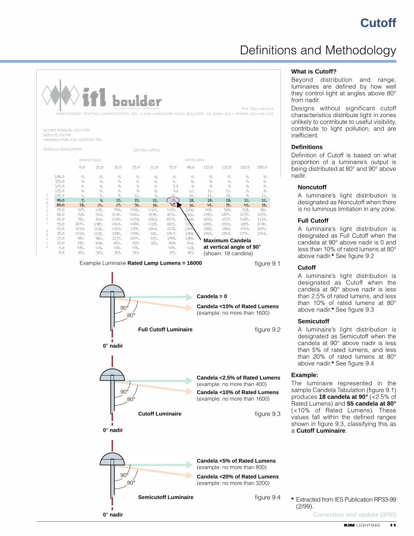
What is Cutoff?Beyond distribution and range,luminaires are defined by how wellthey control light at angles above 80°from nadir.Designs without significant cutoffcharacteristics distribute light in zonesunlikely to contribute to useful visibility,contribute to light pollution, and areinefficient.
DefinitionsDefinition of Cutoff is based on whatproportion of a luminaire’s output isbeing distributed at 80° and 90° abovenadir.
NoncutoffA luminaire’s light distribution isdesignated as Noncutoff when thereis no luminous limitation in any zone.
Full CutoffA luminaire’s light distribution isdesignated as Full Cutoff when thecandela at 90° above nadir is 0 andless than 10% of rated lumens at 80°above nadir.* See figure 9.2
CutoffA luminaire’s light distribution isdesignated as Cutoff when thecandela at 90° above nadir is lessthan 2.5% of rated lumens, and lessthan 10% of rated lumens at 80°above nadir.* See figure 9.3
SemicutoffA luminaire’s light distribution isdesignated as Semicutoff when thecandela at 90° above nadir is lessthan 5% of rated lumens, and lessthan 20% of rated lumens at 80°above nadir.* See figure 9.4
Example:The luminaire represented in thesample Candela Tabulation (figure 9.1)produces 18 candela at 90° (<2.5% ofRated Lumens) and 55 candela at 80°(<10% of Rated Lumens). Thesevalues fall within the defined rangesshown in figure 9.3, classifying this asa Cutoff Luminaire.
* Extracted from IES Publication RP33-99(2/99).
Correction and update (3/00)
KKIIMM LIGHTING 1133
Estimating Spacing and Uniformity
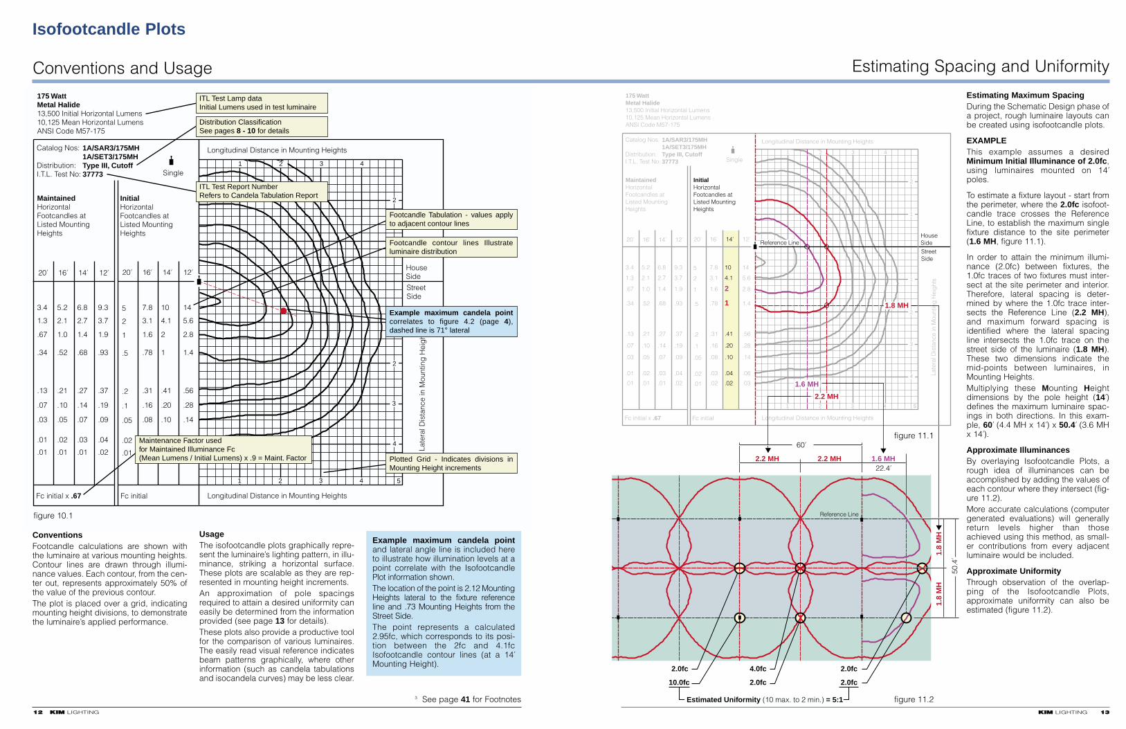
Estimating Maximum SpacingDuring the Schematic Design phase ofa project, rough luminaire layouts canbe created using isofootcandle plots.
EXAMPLEThis example assumes a desiredMinimum Initial Illuminance of 2.0fc,using luminaires mounted on 14'
poles.
To estimate a fixture layout - start fromthe perimeter, where the 2.0fc isofoot-candle trace crosses the ReferenceLine, to establish the maximum singlefixture distance to the site perimeter(1.6 MH, figure 11.1).
In order to attain the minimum illumi-nance (2.0fc) between fixtures, the1.0fc traces of two fixtures must inter-sect at the site perimeter and interior.Therefore, lateral spacing is deter-mined by where the 1.0fc trace inter-sects the Reference Line (2.2 MH),and maximum forward spacing isidentified where the lateral spacingline intersects the 1.0fc trace on thestreet side of the luminaire (1.8 MH).These two dimensions indicate themid-points between luminaires, inMounting Heights.Multiplying these Mounting Heightdimensions by the pole height (14')defines the maximum luminaire spac-ings in both directions. In this exam-ple, 60' (4.4 MH x 14') x 50.4' (3.6 MHx 14').
Approximate IlluminancesBy overlaying Isofootcandle Plots, arough idea of illuminances can beaccomplished by adding the values ofeach contour where they intersect (fig-ure 11.2).More accurate calculations (computergenerated evaluations) will generallyreturn levels higher than thoseachieved using this method, as small-er contributions from every adjacentluminaire would be included.
Approximate UniformityThrough observation of the overlap-ping of the Isofootcandle Plots,approximate uniformity can also beestimated (figure 11.2).
20' 16' 14' 12'20' 16' 14' 12'
MaintainedHorizontalFootcandles atListed MountingHeights
InitialHorizontalFootcandles atListed MountingHeights
3.4
1.3
.67
.34
.13
.07
.03
.01
.01
5.2
2.1
1.0
.52
.21
.10
.05
.02
.01
6.8
2.7
1.4
.68
.27
.14
.07
.03
.01
5
2
1
.5
.2
.1
.05
.02
.01
7.8
3.1
1.6
.78
.31
.16
.08
.03
.02
10
4.1
2
1
.41
.20
.10
.04
.02
14
5.6
2.8
1.4
.56
.28
.14
.06
.03
9.3
3.7
1.9
.93
.37
.19
.09
.04
.02
Fc initial x .67 Fc initial
Catalog Nos: Distribution:I.T.L. Test No:
1A/SAR3/175MH1A/SET3/175MHType III, Cutoff37773
1 2 3 4 5
1 2 3 4
1
2
1
2
3
4
HouseSideStreetSide
Longitudinal Distance in Mounting Heights
Late
ral D
ista
nce
in M
ount
ing
Hei
ght
s
Longitudinal Distance in Mounting Heights
Single
175 WattMetal Halide13,500 Initial Horizontal Lumens10,125 Mean Horizontal LumensANSI Code M57-175
1.8 MH
2.2 MH
Reference Line
2.2 MH
1.8
MH
50.4
'
2.0fc
10.0fc
4.0fc
2.0fc
2.0fc
2.0fc
Estimated Uniformity (10 max. to 2 min.) = 5:1
Reference Line
2.2 MH
1.8
MH
1.6 MH
1.6 MH22.4'
60'
figure 11.1
figure 11.2
Isofootcandle Plots
Conventions and Usage
1122 KKIIMM LIGHTING
ConventionsFootcandle calculations are shown withthe luminaire at various mounting heights.Contour lines are drawn through illumi-nance values. Each contour, from the cen-ter out, represents approximately 50% ofthe value of the previous contour.The plot is placed over a grid, indicatingmounting height divisions, to demonstratethe luminaire’s applied performance.
3 See page 41 for Footnotes
Example maximum candela pointand lateral angle line is included hereto illustrate how illumination levels at apoint correlate with the IsofootcandlePlot information shown. The location of the point is 2.12 MountingHeights lateral to the fixture referenceline and .73 Mounting Heights from theStreet Side.The point represents a calculated2.95fc, which corresponds to its posi-tion between the 2fc and 4.1fcIsofootcandle contour lines (at a 14'
Mounting Height).
20' 16' 14' 12'20' 16' 14' 12'
MaintainedHorizontalFootcandles atListed MountingHeights
InitialHorizontalFootcandles atListed MountingHeights
3.4
1.3
.67
.34
.13
.07
.03
.01
.01
5.2
2.1
1.0
.52
.21
.10
.05
.02
.01
6.8
2.7
1.4
.68
.27
.14
.07
.03
.01
5
2
1
.5
.2
.1
.05
.02
.01
7.8
3.1
1.6
.78
.31
.16
.08
.03
.02
10
4.1
2
1
.41
.20
.10
.04
.02
14
5.6
2.8
1.4
.56
.28
.14
.06
.03
9.3
3.7
1.9
.93
.37
.19
.09
.04
.02
Fc initial x .67 Fc initial
Catalog Nos: Distribution:I.T.L. Test No:
1A/SAR3/175MH1A/SET3/175MHType III, Cutoff37773
1 2 3 4 5
1 2 3 4
1
2
1
2
3
4
HouseSide
StreetSide
Longitudinal Distance in Mounting Heights
Late
ral D
ista
nce
in M
ount
ing
Hei
ght
s
Longitudinal Distance in Mounting Heights
Single
175 WattMetal Halide13,500 Initial Horizontal Lumens10,125 Mean Horizontal LumensANSI Code M57-175
ITL Test Lamp dataInitial Lumens used in test luminaire
Distribution ClassificationSee pages 8 - 10 for details
Plotted Grid - Indicates divisions in Mounting Height increments
3
figure 10.1
Maintenance Factor usedfor Maintained Illuminance Fc (Mean Lumens / Initial Lumens) x .9 = Maint. Factor
ITL Test Report NumberRefers to Candela Tabulation Report
Example maximum candela point correlates to figure 4.2 (page 4), dashed line is 71° lateral
Footcandle contour lines Illustrate luminaire distribution
Footcandle Tabulation - values apply to adjacent contour lines
UsageThe isofootcandle plots graphically repre-sent the luminaire’s lighting pattern, in illu-minance, striking a horizontal surface.These plots are scalable as they are rep-resented in mounting height increments.An approximation of pole spacingsrequired to attain a desired uniformity caneasily be determined from the informationprovided (see page 13 for details).These plots also provide a productive toolfor the comparison of various luminaires.The easily read visual reference indicatesbeam patterns graphically, where otherinformation (such as candela tabulationsand isocandela curves) may be less clear.
1144 KKIIMM LIGHTING
Application
Distribution Pattern Uses
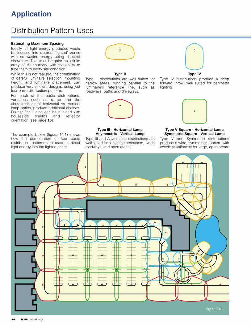
Estimating Maximum SpacingIdeally, all light energy produced wouldbe focused into desired “lighted” zoneswith no wasted energy being directedelsewhere. This would require an infinitearray of distributions, with the ability totune them to every site condition. While this is not realistic, the combinationof careful luminaire selection, mountingheight, and luminaire placement, canproduce very efficient designs, using justfour basic distribution patterns.For each of the basic distributions,variations such as range and thecharacteristics of horizontal vs. verticallamp optics, produce additional choices.Further fine tuning can be attained withhouseside shields and reflectororientation (see page 15).
The example below (figure 14.1) showshow the combination of four basicdistribution patterns are used to directlight energy into the lighted zones.
Type IIType II distributions are well suited fornarrow areas, running parallel to theluminaire's reference line, such asroadways, paths and driveways.
Type IVType IV distributions produce a deepforward throw, well suited for perimeterlighting.
Type III - Horizontal LampAsymmetric - Vertical Lamp
Type III and Asymmetric distributions arewell suited for site / area perimeters, wideroadways, and open areas.
Type V Square - Horizontal LampSymmetric Square - Vertical Lamp
Type V and Symmetric distributionsproduce a wide, symmetrical pattern withexcellent uniformity for large, open areas.
figure 14.1

KKIIMM LIGHTING 1155
Important Features for Fine-Tuning Designs
Square vs. Round DistributionFor large areas, symmetric distributionsprovide maximum pole spacing in bothlateral and longitudinal directions. Rounddistributions, however, do not reach welldiagonally between pole locations,reducing uniformity and requiring shorterdistances between luminaires. Kimsquare distribution patterns arespecifically engineered to maximize polespacing by improving uniformitydiagonally between fixture locations.
Houseside ShieldsWhen luminaires are located close tostructures, or areas where the illuminationemitted on the houseside of the referenceline is objectionable, houseside shieldsoffer additional control.These devices “trim” light emitted by thelamp, as well as light reflected from withinthe optical system. These are applied toType II, Type III and Type IV (horizontallamp) and Asymmetric (vertical lamp)optical systems only.Houseside shields are not applied to Type Vor Symmetric optical systems, as they willnot function properly.
Reflector Orientation / Rotatable OpticsOrientation of luminaires is oftencontrolled by available pole locations andproduct aesthetic design. The luminairehead, arm or yoke may dictate anorientation that varies from the desiredoptical orientation.The ability to rotate optical systemsprovides a high degree of flexibility totailor luminaire performance to specificapplications, while maintaining aestheticcontinuity of the luminaires used.The combination of optical distributions inmultiple luminaire applications producesadditional unique “footprints,” creatingcustomized performance and/orincreased illumination levels to suit a verywide range of needs.The illustrations shown at left are just afew examples based on a simple twinmounting arrangement.
Max./Min. Ratio5:1
Max/Min Ratio4.5:1
4fc
WideSpacing
12fc
20fc
2fc 2fc
9fc
NarrowSpacing
Typical Round Pattern OverlapPoor diagonal overlap requires tighterpole spacing to maintain acceptableuniformity.
Kim Type V Square Pattern OverlapImproved diagonal overlap allows widerpole spacing while maintaining excellentuniformity.
Type II
Type IIIAsymmetric
Type IV
Type IV
Type IV with Houseside Shield Reference Line
Street SideHouse Side
Building Structureor Adjacent Property
Building Structureor Adjacent Property
Type III, AsymmetricType II Type IV
Angled Shield
Street Side House Side
Angled Shield
Street Side House Side
Angled Shield
Street Side House Side Street Side House Side
Flat Shield with Louvers
Raw LampDistribution
ReflectorMain Distribution
System Footprint
Direct distribution from lamp provides illumination directly below luminaire
Raw lamp distribution
CompactProfile
Upper reflector directs light to higher angles
KKIIMM LIGHTING 1177
Design Considerations
Optical System Design
Lamp and Reflector System Integration
1166 KKIIMM LIGHTING
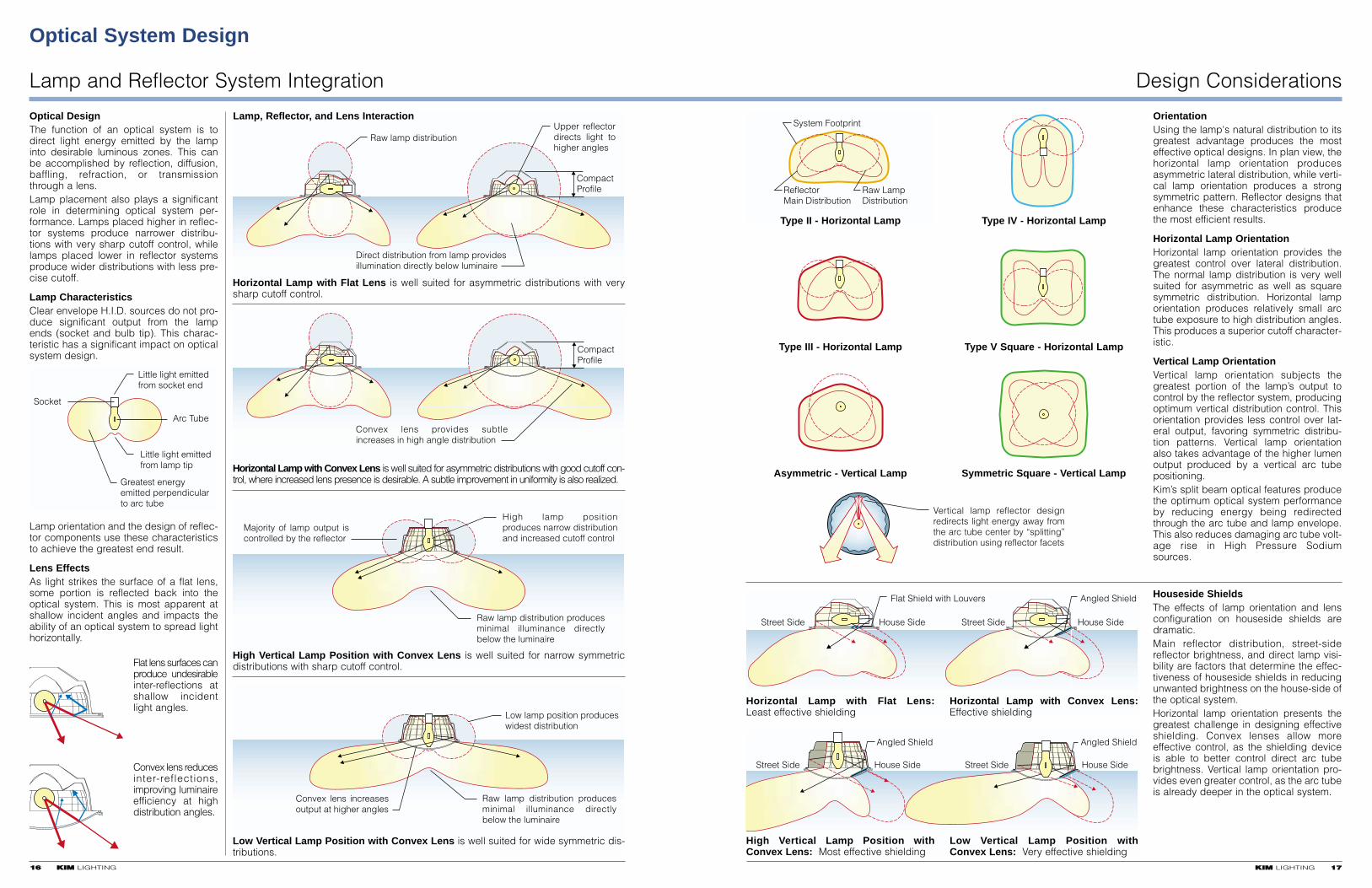
Optical DesignThe function of an optical system is todirect light energy emitted by the lampinto desirable luminous zones. This canbe accomplished by reflection, diffusion,baffling, refraction, or transmissionthrough a lens. Lamp placement also plays a significantrole in determining optical system per-formance. Lamps placed higher in reflec-tor systems produce narrower distribu-tions with very sharp cutoff control, whilelamps placed lower in reflector systemsproduce wider distributions with less pre-cise cutoff.
Lamp CharacteristicsClear envelope H.I.D. sources do not pro-duce significant output from the lampends (socket and bulb tip). This charac-teristic has a significant impact on opticalsystem design.
Lamp orientation and the design of reflec-tor components use these characteristicsto achieve the greatest end result.
Lens EffectsAs light strikes the surface of a flat lens,some portion is reflected back into theoptical system. This is most apparent atshallow incident angles and impacts theability of an optical system to spread lighthorizontally.
Flat lens surfaces canproduce undesirableinter-reflections atshallow incidentlight angles.
Convex lens reducesinter-reflections,improving luminaireefficiency at highdistribution angles.
Little light emitted from socket end
Little light emitted from lamp tip
Greatest energyemitted perpendicularto arc tube
Arc Tube
Socket
Lamp, Reflector, and Lens Interaction
Horizontal Lamp with Flat Lens is well suited for asymmetric distributions with verysharp cutoff control.
CompactProfile
Convex lens provides subtle increases in high angle distribution
Horizontal Lamp with Convex Lens is well suited for asymmetric distributions with good cutoff con-trol, where increased lens presence is desirable. A subtle improvement in uniformity is also realized.
Raw lamp distribution produces minimal illuminance directly below the luminaire
High lamp position produces narrow distribution and increased cutoff control
Majority of lamp output is controlled by the reflector
High Vertical Lamp Position with Convex Lens is well suited for narrow symmetricdistributions with sharp cutoff control.
Low lamp position produceswidest distribution
Raw lamp distribution produces minimal illuminance directly below the luminaire
Convex lens increases output at higher angles
Low Vertical Lamp Position with Convex Lens is well suited for wide symmetric dis-tributions.
OrientationUsing the lamp's natural distribution to itsgreatest advantage produces the mosteffective optical designs. In plan view, thehorizontal lamp orientation producesasymmetric lateral distribution, while verti-cal lamp orientation produces a strongsymmetric pattern. Reflector designs thatenhance these characteristics producethe most efficient results.
Horizontal Lamp OrientationHorizontal lamp orientation provides thegreatest control over lateral distribution.The normal lamp distribution is very wellsuited for asymmetric as well as squaresymmetric distribution. Horizontal lamporientation produces relatively small arctube exposure to high distribution angles.This produces a superior cutoff character-istic.
Vertical Lamp OrientationVertical lamp orientation subjects thegreatest portion of the lamp’s output tocontrol by the reflector system, producingoptimum vertical distribution control. Thisorientation provides less control over lat-eral output, favoring symmetric distribu-tion patterns. Vertical lamp orientationalso takes advantage of the higher lumenoutput produced by a vertical arc tubepositioning.Kim’s split beam optical features producethe optimum optical system performanceby reducing energy being redirectedthrough the arc tube and lamp envelope.This also reduces damaging arc tube volt-age rise in High Pressure Sodiumsources.
Houseside ShieldsThe effects of lamp orientation and lensconfiguration on houseside shields aredramatic. Main reflector distribution, street-sidereflector brightness, and direct lamp visi-bility are factors that determine the effec-tiveness of houseside shields in reducingunwanted brightness on the house-side ofthe optical system. Horizontal lamp orientation presents thegreatest challenge in designing effectiveshielding. Convex lenses allow moreeffective control, as the shielding deviceis able to better control direct arc tubebrightness. Vertical lamp orientation pro-vides even greater control, as the arc tubeis already deeper in the optical system.
Type II - Horizontal Lamp Type IV - Horizontal Lamp
Type III - Horizontal Lamp Type V Square - Horizontal Lamp
Asymmetric - Vertical Lamp Symmetric Square - Vertical Lamp
Vertical lamp reflector design redirects light energy away from the arc tube center by “splitting” distribution using reflector facets
High Vertical Lamp Position withConvex Lens: Most effective shielding
Low Vertical Lamp Position withConvex Lens: Very effective shielding
Horizontal Lamp with Convex Lens:Effective shielding
Horizontal Lamp with Flat Lens:Least effective shielding
Reflector Mechanical Design
General Methods of Construction
1188 KKIIMM LIGHTING
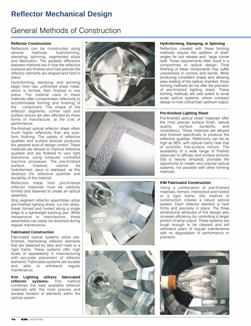
Reflector ConstructionReflectors can be constructed usingseveral methods; hydroforming,stamping, spinning, segmented stripsand fabrication. The greatest differencebetween methods lies in how the reflectivesurfaces are finished and how precise thereflector elements are shaped and held inplace. Hydroforming, stamping, and spinningbegin from raw, unfinished sheet metal,which is formed, then finished in onepiece. The material used in thesemethods often compromises reflectivity toaccommodate forming and finishing ofthe component. The shape of thereflector segments, corner radii andsurface texture are also affected by theseforms of manufacture, at the cost ofperformance.Pre-finished optical reflector sheet offersmuch higher reflectivity than any post-form finishing. The variety of reflectivequalities and surface textures producesthe greatest level of design control. Thesematerials are alloyed to improve reflectivequalities and are finished to very tighttolerances, using computer controlledmachine processes. The pre-finishedsurface, however, cannot behydroformed, spun or stamped, as thisdestroys the reflective qualities anddurability of the material. Reflectors made from pre-finishedreflector materials must be carefullyformed and fastened to create an opticalassembly.Strip segment reflector assemblies utilizepre-finished lighting sheet, cut into strips,break formed and riveted along a singleedge to a lightweight backing pan. Whileinexpensive to manufacture, theseassemblies can easily be distorted duringregular maintenance.
Fabricated ConstructionFabricated optical systems utilize pre-finished, interlocking reflector elementsthat are fastened by tabs and rivets to arigid frame. These systems offer highlevels of repeatability in manufacturingwith accurate placement of reflectorelements. Fabricated systems are durableand able to withstand regularmaintenance.
Kim Lighting utilizes fabricatedreflector systems. This methodcombines the best available reflectormaterials with the most precise anddurable location of elements within theoptical system.
Hydroforming, Stamping, or SpinningReflectors created with these formingmethods require the addition of draft-angles for tool release and large cornerradii. These requirements often result in acompromise to optical design. Finalfinishing of these components may sufferunevenness in corners and bends. Whileproducing consistent shape and allowingeasy sealing of the optical chamber, theseforming methods do not offer the precisionof pre-finished lighting sheet. Theseforming methods are well suited to smallscale optical systems, where compactdesign is more critical than optimum output.
Pre-finished Lighting SheetPre-finished optical sheet materials offerthe most precise surface finish, opticalquality, surface durability andconsistency. These materials are alloyedand finished specifically to produce thereflective qualities. Reflectivity can be ashigh as 98%, with optical clarity near thatof scientific first-surface mirrors. Theavailability of a wide range of finishes(specular to diffuse) and surface textures(flat to heavily dimpled), provides theopportunity to create very precise opticalsystems, not possible with other formingmethods.
KIM Fabricated ConstructionUsing a combination of pre-finishedmaterials, formed, interlocked and rivetedto a rigid frame, this method ofconstruction creates a robust opticalsystem. Each reflector element is heldfirmly and precisely in place. The threedimensional attributes of this design alsoincrease efficiency by controlling a largerportion of lamp output. These systems aretough enough to be cleaned and willwithstand years of regular maintenancewith no degradation of performance orprecision.
KKIIMM LIGHTING 1199
Fabricated Construction Features
Kim Optical Systems
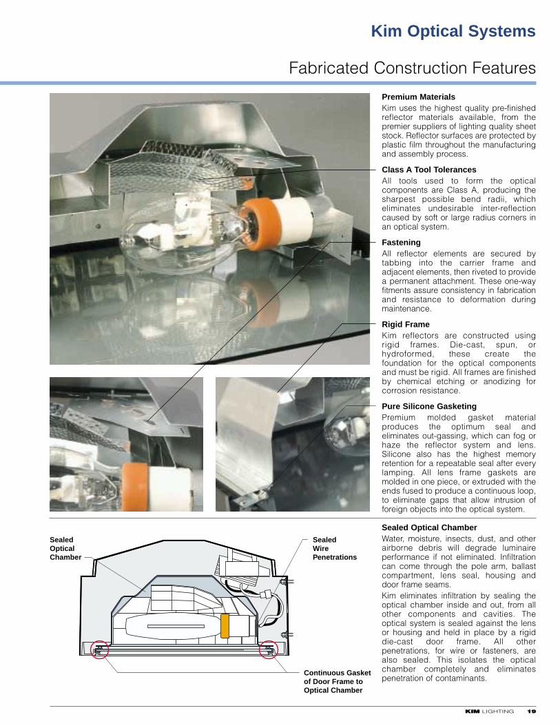
Premium MaterialsKim uses the highest quality pre-finishedreflector materials available, from thepremier suppliers of lighting quality sheetstock. Reflector surfaces are protected byplastic film throughout the manufacturingand assembly process.
Class A Tool TolerancesAll tools used to form the opticalcomponents are Class A, producing thesharpest possible bend radii, whicheliminates undesirable inter-reflectioncaused by soft or large radius corners inan optical system.
FasteningAll reflector elements are secured bytabbing into the carrier frame andadjacent elements, then riveted to providea permanent attachment. These one-wayfitments assure consistency in fabricationand resistance to deformation duringmaintenance.
Rigid FrameKim reflectors are constructed usingrigid frames. Die-cast, spun, orhydroformed, these create thefoundation for the optical componentsand must be rigid. All frames are finishedby chemical etching or anodizing forcorrosion resistance.
Pure Silicone GasketingPremium molded gasket materialproduces the optimum seal andeliminates out-gassing, which can fog orhaze the reflector system and lens.Silicone also has the highest memoryretention for a repeatable seal after everylamping. All lens frame gaskets aremolded in one piece, or extruded with theends fused to produce a continuous loop,to eliminate gaps that allow intrusion offoreign objects into the optical system.
Sealed Optical ChamberWater, moisture, insects, dust, and otherairborne debris will degrade luminaireperformance if not eliminated. Infiltrationcan come through the pole arm, ballastcompartment, lens seal, housing anddoor frame seams.Kim eliminates infiltration by sealing theoptical chamber inside and out, from allother components and cavities. Theoptical system is sealed against the lensor housing and held in place by a rigiddie-cast door frame. All otherpenetrations, for wire or fasteners, arealso sealed. This isolates the opticalchamber completely and eliminatespenetration of contaminants.
SealedOpticalChamber
SealedWirePenetrations
Continuous Gasketof Door Frame toOptical Chamber
Kim Optical Systems
Three Core Systems for Maximum Adaptability
2200 KKIIMM LIGHTING
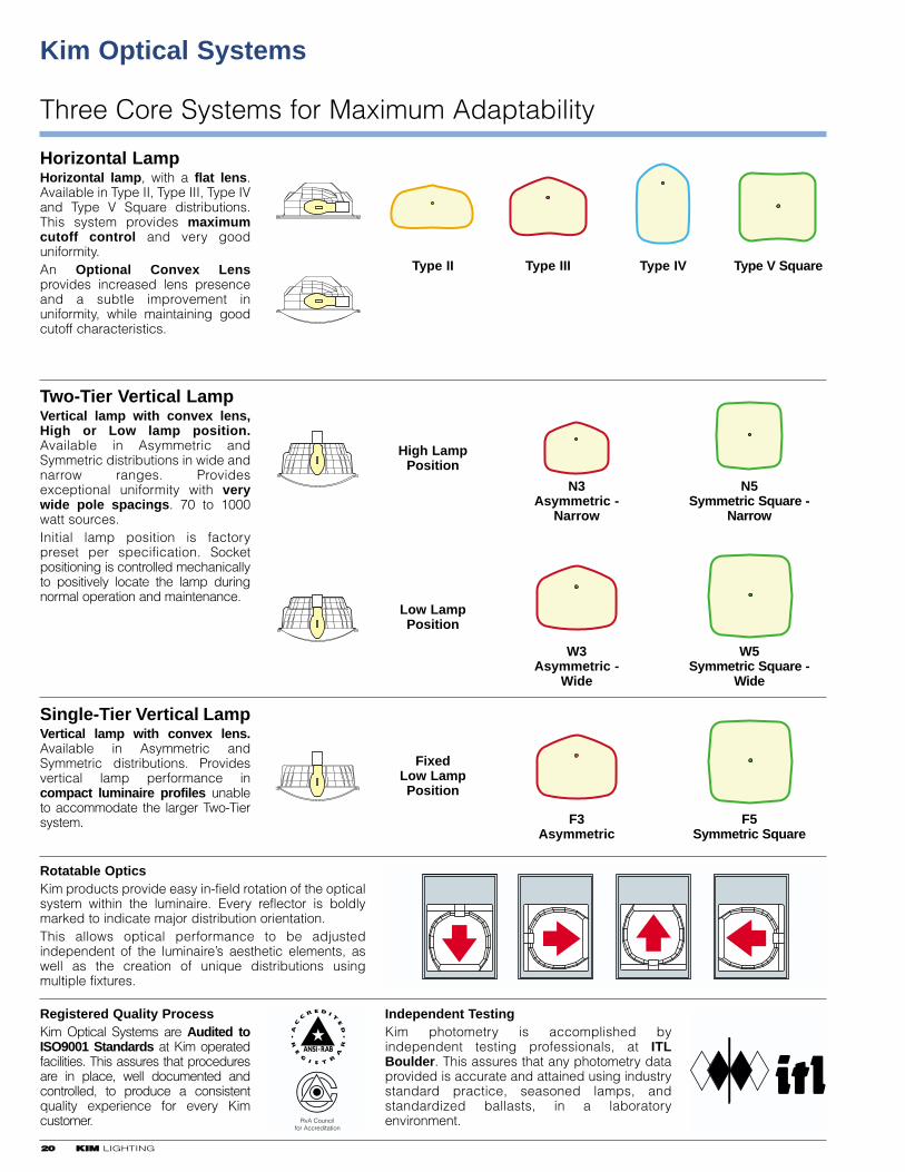
Horizontal LampHorizontal lamp, with a flat lens.Available in Type II, Type III, Type IVand Type V Square distributions.This system provides maximumcutoff control and very gooduniformity.An Optional Convex Lensprovides increased lens presenceand a subtle improvement inuniformity, while maintaining goodcutoff characteristics.
Two-Tier Vertical LampVertical lamp with convex lens,High or Low lamp position.Available in Asymmetric andSymmetric distributions in wide andnarrow ranges. Providesexceptional uniformity with verywide pole spacings. 70 to 1000watt sources.Initial lamp position is factorypreset per specification. Socketpositioning is controlled mechanicallyto positively locate the lamp duringnormal operation and maintenance.
Single-Tier Vertical LampVertical lamp with convex lens.Available in Asymmetric andSymmetric distributions. Providesvertical lamp performance incompact luminaire profiles unableto accommodate the larger Two-Tiersystem.
Registered Quality ProcessKim Optical Systems are Audited toISO9001 Standards at Kim operatedfacilities. This assures that proceduresare in place, well documented andcontrolled, to produce a consistentquality experience for every Kimcustomer.
Type II Type III Type IV Type V Square
N3Asymmetric -
Narrow
N5Symmetric Square -
Narrow
W3Asymmetric -
Wide
W5Symmetric Square -
Wide
F3Asymmetric
F5Symmetric Square
Independent TestingKim photometry is accomplished byindependent testing professionals, at ITLBoulder. This assures that any photometry dataprovided is accurate and attained using industrystandard practice, seasoned lamps, andstandardized ballasts, in a laboratoryenvironment. RvA Council
for Accreditation
High LampPosition
Low LampPosition
FixedLow LampPosition
Rotatable OpticsKim products provide easy in-field rotation of the opticalsystem within the luminaire. Every reflector is boldlymarked to indicate major distribution orientation. This allows optical performance to be adjustedindependent of the luminaire’s aesthetic elements, aswell as the creation of unique distributions usingmultiple fixtures.
KKIIMM LIGHTING 2211

Kim Horizontal Lamp Luminaires
2222 KKIIMM LIGHTING
The Archetype®
AR – 150-400 HPS175-400 MH
SAR – 70-150 HPS70-175 MH
Type II, Type III, Type IV, andType V Square
The Entablature®
ET – 150-400 HPS175-400 MH
SET – 70-150 HPS70-175 MH
Type II, Type III, Type IV, andType V Square
Matrix™
MX21 – 150-400 HPS175-400 MH
Type II, Type III, Type IV, andType V Square
Also available with VerticalLamp Optics.
Curvilinear Cutoff17, 21, 25, and 29" Diameters
CC/CCS – 70-1000 HPS70-1000 MH
Type II, Type III, Type IV, andType V Square
Also available with VerticalLamp Optics.
NeoSphere®
NS1 – Hemispherical LensNS2 – Flat Lens
70-150 HPS70-175 MH
Type II, Type III, Type IV, andType V Square
Also available with VerticalLamp Optics.
Wide Throw HorizontalWTH – 150-250 HPS
175-250 MH
Type II, Type III, Type IV, andType V Square
Also available with VerticalLamp Optics.
KKIIMM LIGHTING 2233
Kim Vertical Lamp Luminaires
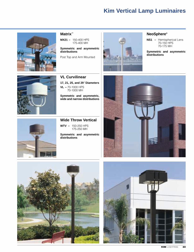
Matrix™
MX21 – 150-400 HPS175-400 MH
Symmetric and asymmetricdistributions
Post Top and Arm Mounted
VL Curvilinear17, 21, 25, and 29" Diameters
VL – 70-1000 HPS70-1000 MH
Symmetric and asymmetric,wide and narrow distributions
Wide Throw VerticalWTV – 150-250 HPS
175-250 MH
Symmetric and asymmetricdistributions
NeoSphere®
NS1 – Hemispherical Lens70-150 HPS70-175 MH
Symmetric and asymmetricdistributions
2244 KKIIMM LIGHTING
KKIIMM LIGHTING 2255
Horizontal Lamp
All Kim Horizontal MH socketsare pin-oriented (except pulsestart) and include a moldedsilicone lamp stabilizer.
Molded Lamp Stabilizer
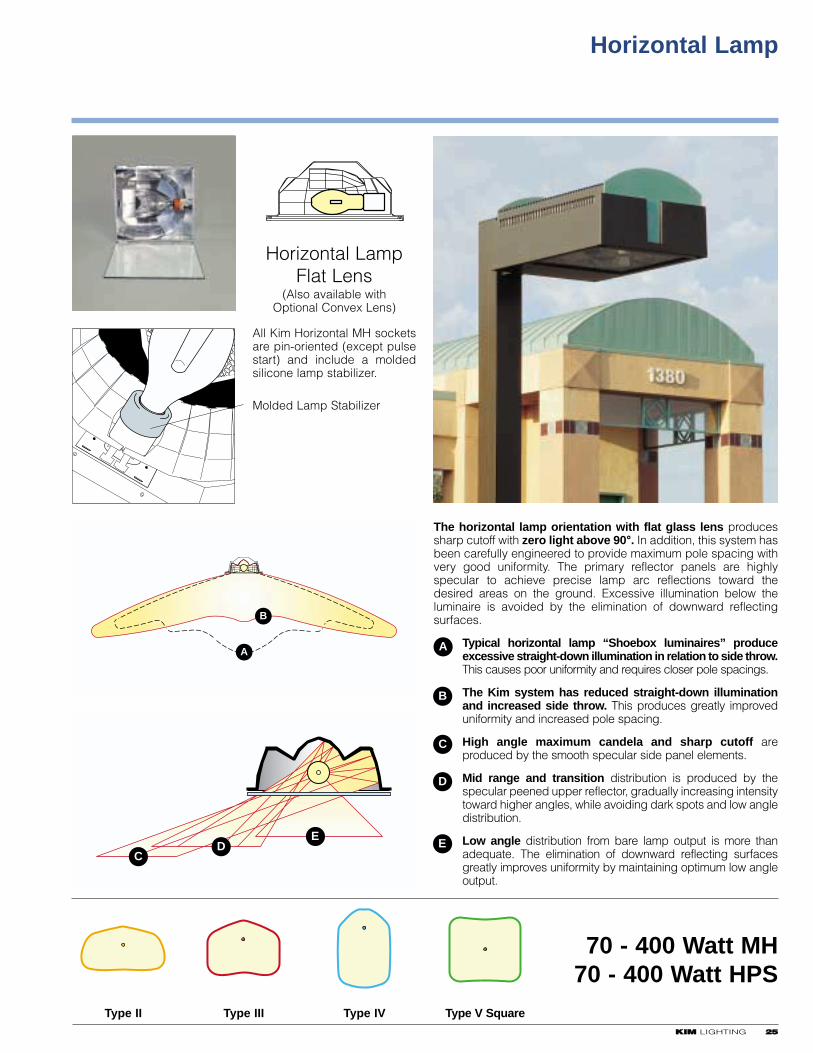
The horizontal lamp orientation with flat glass lens producessharp cutoff with zero light above 90°. In addition, this system hasbeen carefully engineered to provide maximum pole spacing withvery good uniformity. The primary reflector panels are highlyspecular to achieve precise lamp arc reflections toward thedesired areas on the ground. Excessive illumination below theluminaire is avoided by the elimination of downward reflectingsurfaces.
Typical horizontal lamp “Shoebox luminaires” produceexcessive straight-down illumination in relation to side throw.This causes poor uniformity and requires closer pole spacings.
The Kim system has reduced straight-down illuminationand increased side throw. This produces greatly improveduniformity and increased pole spacing.
High angle maximum candela and sharp cutoff areproduced by the smooth specular side panel elements.
Mid range and transition distribution is produced by thespecular peened upper reflector, gradually increasing intensitytoward higher angles, while avoiding dark spots and low angledistribution.
Low angle distribution from bare lamp output is more thanadequate. The elimination of downward reflecting surfacesgreatly improves uniformity by maintaining optimum low angleoutput.
B
A
CD
E
Type II Type III Type IV Type V Square
70 - 400 Watt MH70 - 400 Watt HPS
A
B
C
D
E
Horizontal LampFlat Lens
(Also available with Optional Convex Lens)
Horizontal Lamp
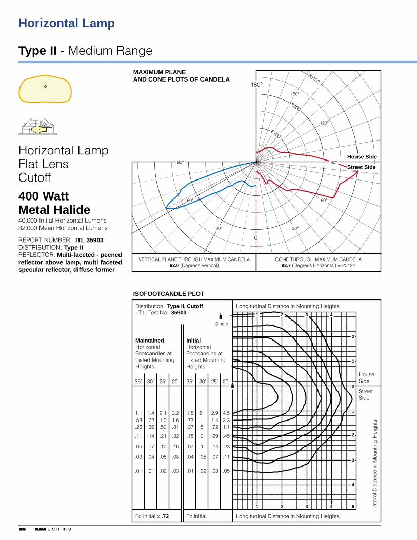
Type II - Medium Range
2266 KKIIMM LIGHTING
35' 30' 25' 20'35' 30' 25' 20'
MaintainedHorizontalFootcandles atListed MountingHeights
InitialHorizontalFootcandles atListed MountingHeights
1.1.53.26
.11
.05
.03
.01
1.4.72.36
.14
.07
.04
.01
2.11.0.52
.21
.10
.05
.02
1.5.73.37
.15
.07
.04
.01
21.5
.2
.1
.05
.02
2.91.4.72
.29
.14
.07
.03
4.52.31.1
.45
.23
.11
.05
3.21.6.81
.32
.16
.08
.03
Distribution: Type II, CutoffI.T.L. Test No: 35903
Single
Fc initial x .72
VERTICAL PLANE THROUGH MAXIMUM CANDELA63.0 (Degrees Vertical)
CONE THROUGH MAXIMUM CANDELA83.7 (Degrees Horizontal) = 20122
Fc initial
HouseSide
StreetSide
Longitudinal Distance in Mounting Heights
Late
ral D
ista
nce
in M
ount
ing
Hei
ght
s
Longitudinal Distance in Mounting Heights
ISOFOOTCANDLE PLOT
1
1
2
2
3
3
4
4
2
0
1
1
2
3
4
5
MAXIMUM PLANE AND CONE PLOTS OF CANDELA
House Side
Street Side
0
180°
30°
60°
90°
30°
60°
90°
6700
13400
20100
150°
120°
Horizontal LampFlat LensCutoff
400 WattMetal Halide40,000 Initial Horizontal Lumens32,000 Mean Horizontal Lumens
REPORT NUMBER: ITL 35903DISTRIBUTION: Type IIREFLECTOR: Multi-faceted - peenedreflector above lamp, multi facetedspecular reflector, diffuse former
2266 KKIIMM LIGHTING
KKIIMM LIGHTING 2277
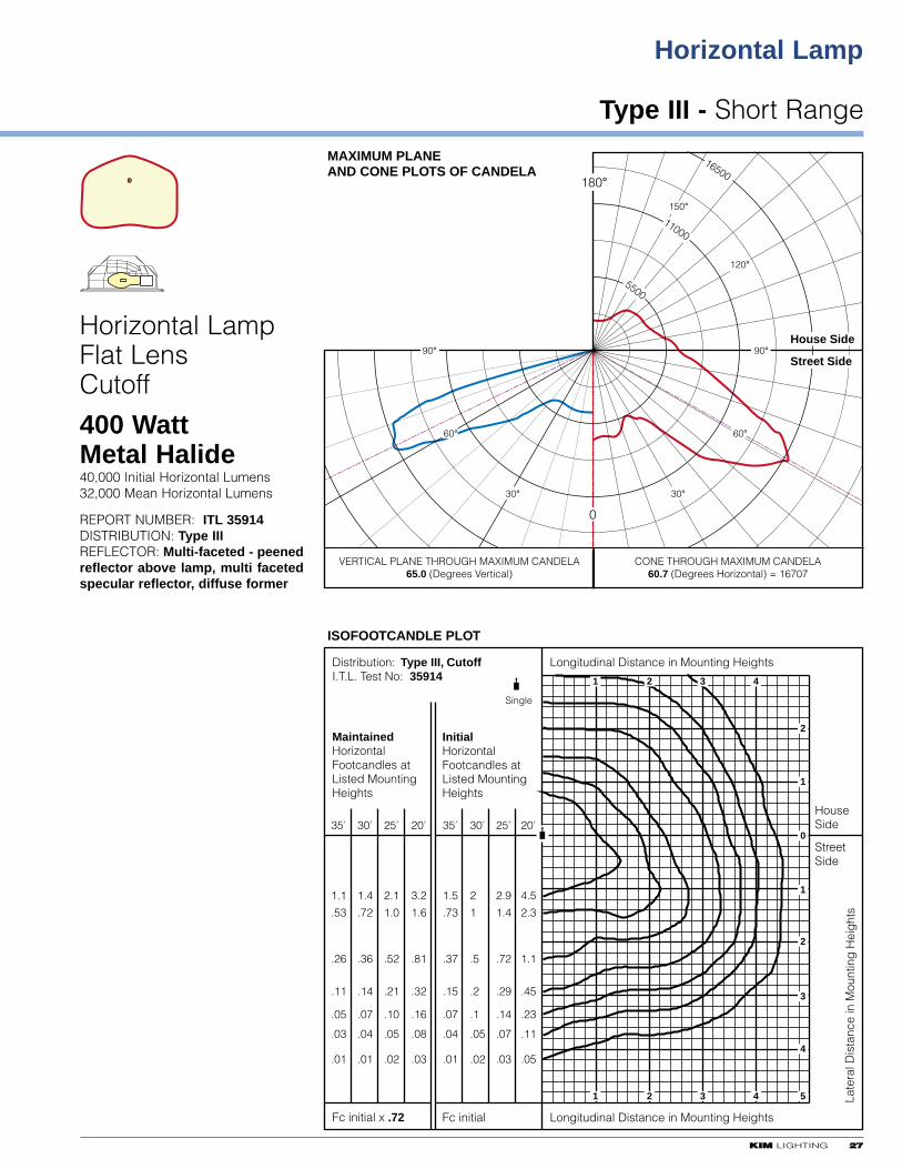
Type III - Short Range
Horizontal Lamp
35' 30' 25' 20'35' 30' 25' 20'
MaintainedHorizontalFootcandles atListed MountingHeights
InitialHorizontalFootcandles atListed MountingHeights
1.1
.53
.26
.11
.05
.03
.01
1.4
.72
.36
.14
.07
.04
.01
2.1
1.0
.52
.21
.10
.05
.02
1.5
.73
.37
.15
.07
.04
.01
2
1
.5
.2
.1
.05
.02
2.9
1.4
.72
.29
.14
.07
.03
4.5
2.3
1.1
.45
.23
.11
.05
3.2
1.6
.81
.32
.16
.08
.03
Distribution: Type III, CutoffI.T.L. Test No: 35914
Single
Fc initial x .72
VERTICAL PLANE THROUGH MAXIMUM CANDELA65.0 (Degrees Vertical)
CONE THROUGH MAXIMUM CANDELA60.7 (Degrees Horizontal) = 16707
Fc initial
HouseSide
StreetSide
Longitudinal Distance in Mounting Heights
Late
ral D
ista
nce
in M
ount
ing
Hei
ght
s
Longitudinal Distance in Mounting Heights
ISOFOOTCANDLE PLOT
1
1
2
2
3
3
4
4
2
0
1
1
2
3
4
5
MAXIMUM PLANE AND CONE PLOTS OF CANDELA
House Side
Street Side
0
180°
30°
60°
90°
30°
60°
90°
5500
11000
16500
150°
120°
Horizontal LampFlat LensCutoff
400 WattMetal Halide40,000 Initial Horizontal Lumens32,000 Mean Horizontal Lumens
REPORT NUMBER: ITL 35914DISTRIBUTION: Type IIIREFLECTOR: Multi-faceted - peenedreflector above lamp, multi facetedspecular reflector, diffuse former
Horizontal Lamp
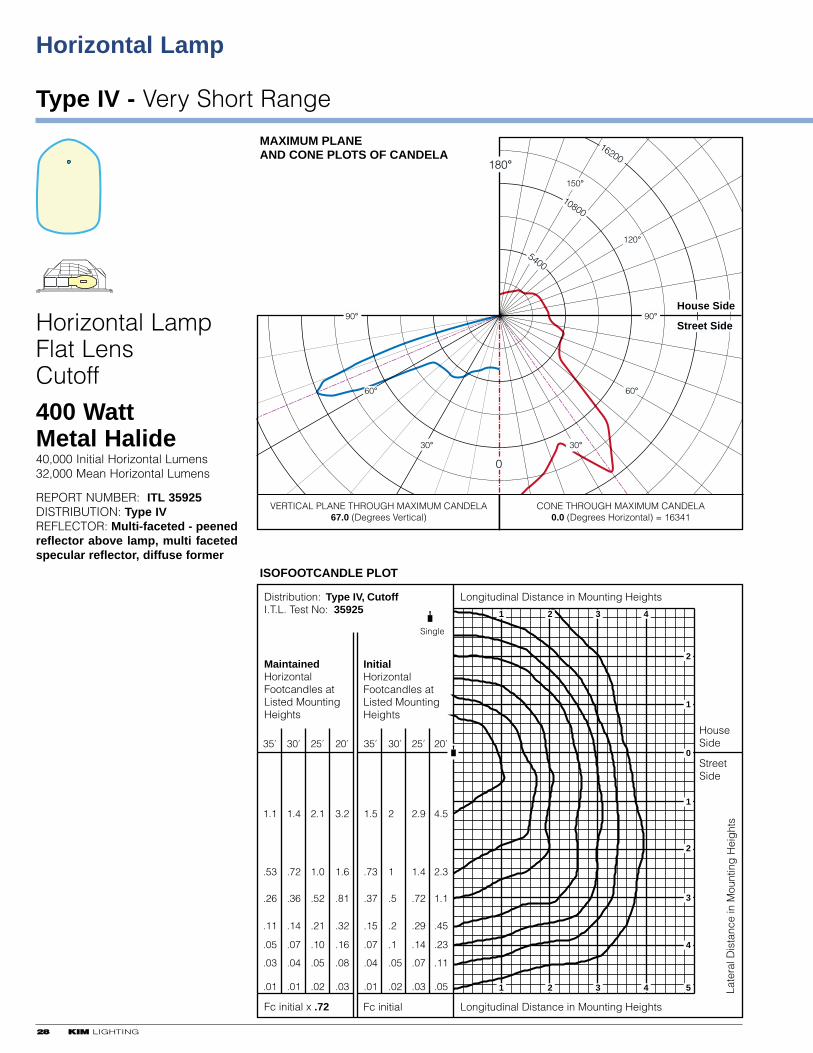
Type IV - Very Short Range
2288 KKIIMM LIGHTING
35' 30' 25' 20'35' 30' 25' 20'
MaintainedHorizontalFootcandles atListed MountingHeights
InitialHorizontalFootcandles atListed MountingHeights
1.1
.53
.26
.11
.05
.03
.01
1.4
.72
.36
.14
.07
.04
.01
2.1
1.0
.52
.21
.10
.05
.02
1.5
.73
.37
.15
.07
.04
.01
2
1
.5
.2
.1
.05
.02
2.9
1.4
.72
.29
.14
.07
.03
4.5
2.3
1.1
.45
.23
.11
.05
3.2
1.6
.81
.32
.16
.08
.03
Distribution: Type IV, CutoffI.T.L. Test No: 35925
Single
Fc initial x .72
VERTICAL PLANE THROUGH MAXIMUM CANDELA67.0 (Degrees Vertical)
CONE THROUGH MAXIMUM CANDELA0.0 (Degrees Horizontal) = 16341
Fc initial
HouseSide
StreetSide
Longitudinal Distance in Mounting Heights
Late
ral D
ista
nce
in M
ount
ing
Hei
ght
s
Longitudinal Distance in Mounting Heights
ISOFOOTCANDLE PLOT
1
1
2
2
3
3
4
4
2
0
1
1
2
3
4
5
MAXIMUM PLANE AND CONE PLOTS OF CANDELA
House Side
Street Side
0
180°
30°
60°
90°
30°
60°
90°
5400
10800
16200
150°
120°
Horizontal LampFlat LensCutoff
400 WattMetal Halide40,000 Initial Horizontal Lumens32,000 Mean Horizontal Lumens
REPORT NUMBER: ITL 35925 DISTRIBUTION: Type IVREFLECTOR: Multi-faceted - peenedreflector above lamp, multi facetedspecular reflector, diffuse former
KKIIMM LIGHTING 2299
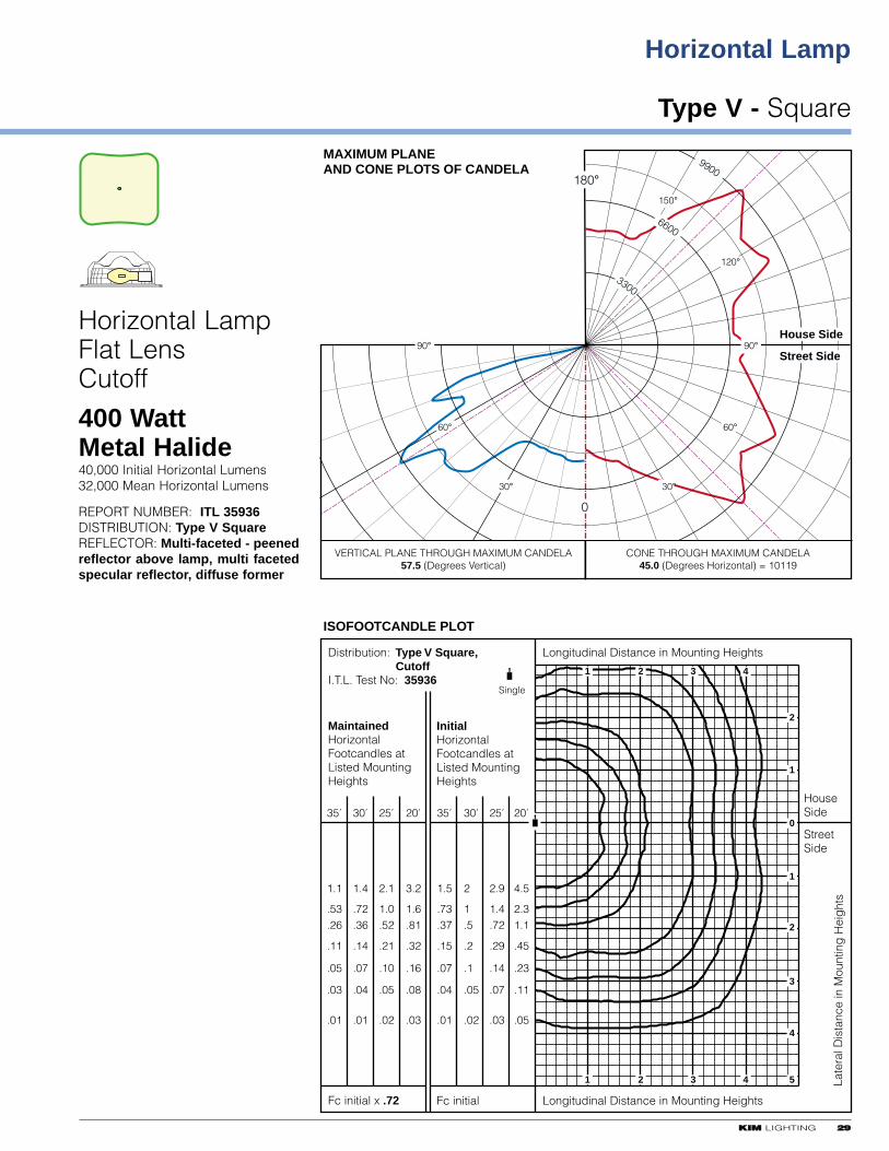
Type V - Square
Horizontal Lamp
35' 30' 25' 20'35' 30' 25' 20'
MaintainedHorizontalFootcandles atListed MountingHeights
InitialHorizontalFootcandles atListed MountingHeights
1.1
.53
.26
.11
.05
.03
.01
1.4
.72
.36
.14
.07
.04
.01
2.1
1.0.52
.21
.10
.05
.02
1.5
.73
.37
.15
.07
.04
.01
2
1.5
.2
.1
.05
.02
2.9
1.4.72
.29
.14
.07
.03
4.5
2.31.1
.45
.23
.11
.05
3.2
1.6.81
.32
.16
.08
.03
Distribution: Type V Square,Cutoff
I.T.L. Test No: 35936Single
Fc initial x .72
VERTICAL PLANE THROUGH MAXIMUM CANDELA57.5 (Degrees Vertical)
CONE THROUGH MAXIMUM CANDELA45.0 (Degrees Horizontal) = 10119
Fc initial
HouseSide
StreetSide
Longitudinal Distance in Mounting Heights
Late
ral D
ista
nce
in M
ount
ing
Hei
ght
s
Longitudinal Distance in Mounting Heights
ISOFOOTCANDLE PLOT
1
1
2
2
3
3
4
4
2
0
1
1
2
3
4
5
MAXIMUM PLANE AND CONE PLOTS OF CANDELA
House Side
Street Side
0
180°
30°
60°
90°
30°
60°
90°
3300
6600
9900
150°
120°
Horizontal LampFlat LensCutoff
400 WattMetal Halide40,000 Initial Horizontal Lumens32,000 Mean Horizontal Lumens
REPORT NUMBER: ITL 35936DISTRIBUTION: Type V SquareREFLECTOR: Multi-faceted - peenedreflector above lamp, multi facetedspecular reflector, diffuse former

Horizontal Lamp
Flat Louvered Shield for Horizontal Lamp with Flat Lens
3300 KKIIMM LIGHTING
Street Side House Side
Streetside distribution passesthrough louver
Houseside distributionreduced with insert on streetside of reflector
Houseside distributionblocked by shield
Houseside Shield: Stamped aluminum with louvers that pass streetside light and blockhouseside light. Clear anodized finish. Attaches to lens frame on any of four sides toinsure correct orientation with reflector. Black panel added to reflector on the street sideto reduce houseside reflection. Use with clear lamps only. Not for use on Type V Squaredistributions
35' 30' 25' 20'
InitialHorizontalFootcandles atListed MountingHeights
1.5
.73
.37
.15
.07
.04
.01
2
1
.5
.2
.1
.05
.02
2.9
1.4
.72
.29
.14
.07
.03
4.5
2.3
1.1
.45
.23
.11
.05
Single
Fc initial
HouseSide
StreetSide
Longitudinal Distance in Mounting Heights
Late
ral D
ista
nce
in M
ount
ing
Hei
ght
s
Longitudinal Distance in Mounting Heights
1
1
2
2
3
3
4
4
2
0
1
1
2
3
4
5
HorizontalLampType IV400 WattMetal Halide
WithFlat Lens /HousesideShield
ITL Test No.36046
Street Side House Side
Shield allows streetside distributionto pass unobstructed
Houseside distributionblocked by shield
Houseside distributionreduced with insert on streetside of reflector
Houseside Shield: Stamped aluminum. Clear anodized finish. Attaches to lens frame(or reflector frame) on any of four sides to insure correct orientation with reflector. Blackpanel added to reflector to reduce houseside reflection. Use with clear lamps only. Notfor use on Type V distributions.
Formed Shields for Horizontal Lamp with Optional Convex Lens
KKIIMM LIGHTING 3311
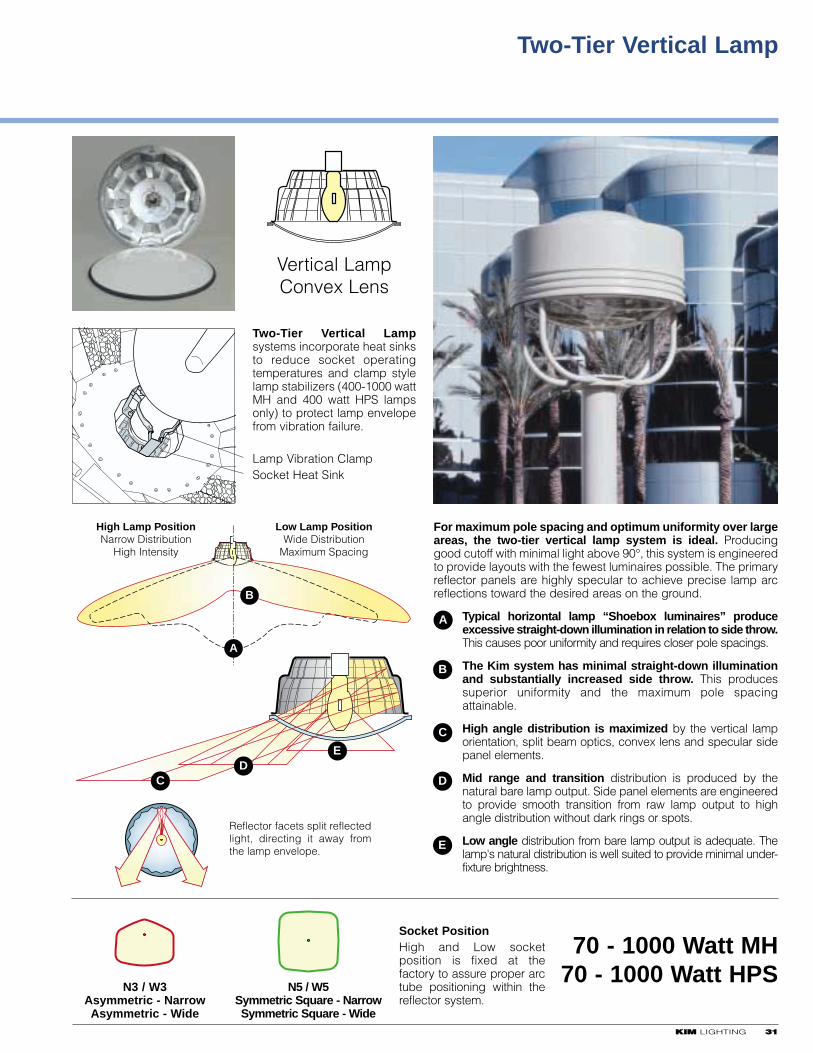
Two-Tier Vertical Lamp
Two-Tier Vertical Lampsystems incorporate heat sinksto reduce socket operatingtemperatures and clamp stylelamp stabilizers (400-1000 wattMH and 400 watt HPS lampsonly) to protect lamp envelopefrom vibration failure.
Lamp Vibration ClampSocket Heat Sink
For maximum pole spacing and optimum uniformity over largeareas, the two-tier vertical lamp system is ideal. Producinggood cutoff with minimal light above 90°, this system is engineeredto provide layouts with the fewest luminaires possible. The primaryreflector panels are highly specular to achieve precise lamp arcreflections toward the desired areas on the ground.
Typical horizontal lamp “Shoebox luminaires” produceexcessive straight-down illumination in relation to side throw.This causes poor uniformity and requires closer pole spacings.
The Kim system has minimal straight-down illuminationand substantially increased side throw. This producessuperior uniformity and the maximum pole spacingattainable.
High angle distribution is maximized by the vertical lamporientation, split beam optics, convex lens and specular sidepanel elements.
Mid range and transition distribution is produced by thenatural bare lamp output. Side panel elements are engineeredto provide smooth transition from raw lamp output to highangle distribution without dark rings or spots.
Low angle distribution from bare lamp output is adequate. Thelamp's natural distribution is well suited to provide minimal under-fixture brightness.
B
A
Low Lamp PositionWide Distribution
Maximum Spacing
High Lamp PositionNarrow Distribution
High Intensity
E
CD
N3 / W3Asymmetric - NarrowAsymmetric - Wide
N5 / W5Symmetric Square - NarrowSymmetric Square - Wide
Socket PositionHigh and Low socketposition is fixed at thefactory to assure proper arctube positioning within thereflector system.
70 - 1000 Watt MH70 - 1000 Watt HPS
A
B
C
D
E
Reflector facets split reflected light, directing it away from the lamp envelope.
Vertical LampConvex Lens
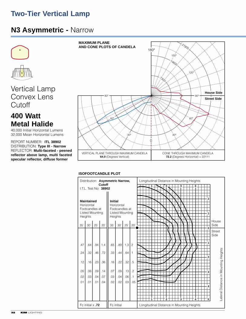
Two-Tier Vertical Lamp
N3 Asymmetric - Narrow
3322 KKIIMM LIGHTING
35' 30' 25' 20'35' 30' 25' 20'
MaintainedHorizontalFootcandles atListed MountingHeights
InitialHorizontalFootcandles atListed MountingHeights
.65
.33
.16
.07
.03
.02
.89
.44
.22
.09
.04
.02
1.3
.64
.32
.13
.06
.03
2
1
.5
.2
.1
.05
.47
.24
.12
.05
.02
.01
.64
.32
.16
.06
.03
.01
.94
.46
.23
.09
.04
.01
1.4
.72
.36
.14
.07
.04
Distribution: Asymmetric Narrow,Cutoff
I.T.L. Test No: 38902
Fc initial x .72
VERTICAL PLANE THROUGH MAXIMUM CANDELA64.0 (Degrees Vertical)
CONE THROUGH MAXIMUM CANDELA72.2 (Degrees Horizontal) = 22111
Fc initial
HouseSide
StreetSide
Longitudinal Distance in Mounting Heights
Late
ral D
ista
nce
in M
ount
ing
Hei
ght
s
Longitudinal Distance in Mounting Heights
ISOFOOTCANDLE PLOT
1
1
2
2
3
3
4
4
2
0
1
1
2
3
4
5
MAXIMUM PLANE AND CONE PLOTS OF CANDELA
House Side
Street Side
0
180°
30°
60°
90°
30°
60°
90°
7300
14600
21900
150°
120°
Vertical LampConvex LensCutoff
400 WattMetal Halide40,000 Initial Horizontal Lumens32,000 Mean Horizontal Lumens
REPORT NUMBER: ITL 38902DISTRIBUTION: Type III - NarrowREFLECTOR: Multi-faceted - peenedreflector above lamp, multi facetedspecular reflector, diffuse former
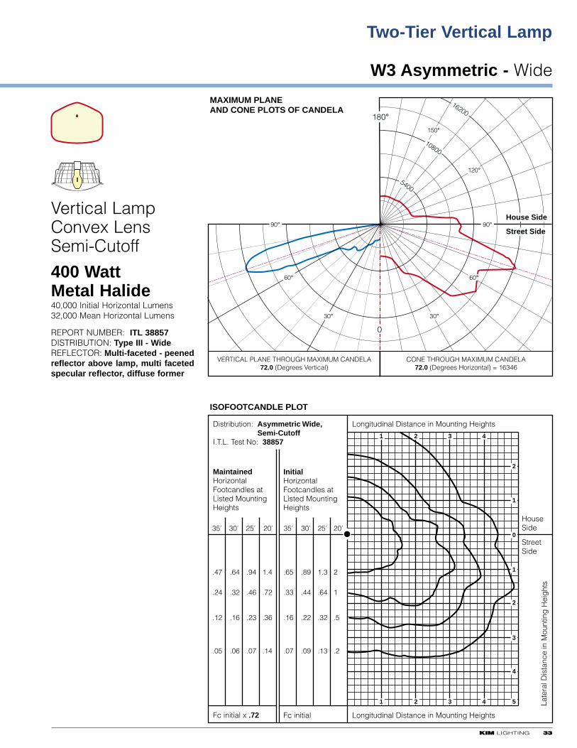
KKIIMM LIGHTING 3333
W3 Asymmetric - Wide
Two-Tier Vertical Lamp
35' 30' 25' 20'35' 30' 25' 20'
MaintainedHorizontalFootcandles atListed MountingHeights
InitialHorizontalFootcandles atListed MountingHeights
.65
.33
.16
.07
.89
.44
.22
.09
1.3
.64
.32
.13
2
1
.5
.2
.47
.24
.12
.05
.64
.32
.16
.06
.94
.46
.23
.07
1.4
.72
.36
.14
Distribution: Asymmetric Wide,Semi-Cutoff
I.T.L. Test No: 38857
Fc initial x .72
VERTICAL PLANE THROUGH MAXIMUM CANDELA72.0 (Degrees Vertical)
CONE THROUGH MAXIMUM CANDELA72.0 (Degrees Horizontal) = 16346
Fc initial
HouseSide
StreetSide
Longitudinal Distance in Mounting Heights
Late
ral D
ista
nce
in M
ount
ing
Hei
ght
s
Longitudinal Distance in Mounting Heights
ISOFOOTCANDLE PLOT
1
1
2
2
3
3
4
4
2
0
1
1
2
3
4
5
MAXIMUM PLANE AND CONE PLOTS OF CANDELA
House Side
Street Side
0
180°
30°
60°
90°
30°
60°
90°
5400
10800
16200
150°
120°
Vertical LampConvex LensSemi-Cutoff
400 WattMetal Halide40,000 Initial Horizontal Lumens32,000 Mean Horizontal Lumens
REPORT NUMBER: ITL 38857DISTRIBUTION: Type III - WideREFLECTOR: Multi-faceted - peenedreflector above lamp, multi facetedspecular reflector, diffuse former
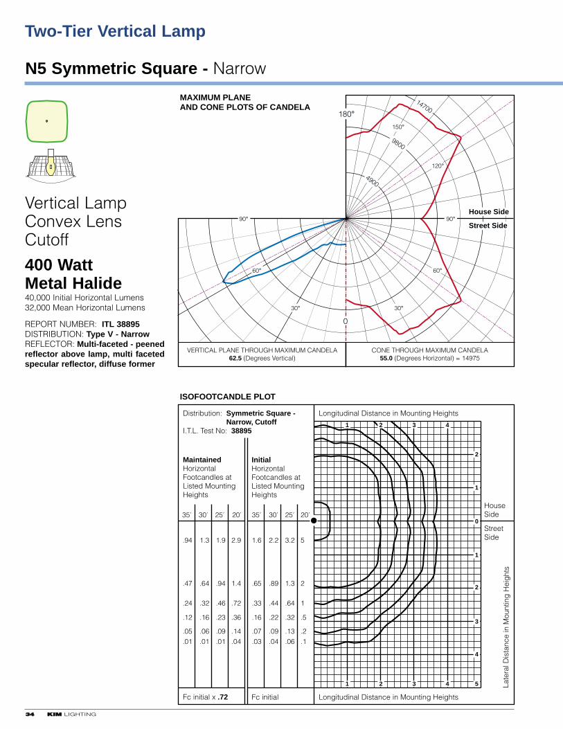
Two-Tier Vertical Lamp
N5 Symmetric Square - Narrow
3344 KKIIMM LIGHTING
35' 30' 25' 20'35' 30' 25' 20'
MaintainedHorizontalFootcandles atListed MountingHeights
InitialHorizontalFootcandles atListed MountingHeights
1.6
.65
.33
.16
.07
.03
2.2
.89
.44
.22
.09
.04
3.2
1.3
.64
.32
.13
.06
5
2
1
.5
.2
.1
.94
.47
.24
.12
.05
.01
1.3
.64
.32
.16
.06
.01
1.9
.94
.46
.23
.09
.01
2.9
1.4
.72
.36
.14
.04
Distribution: Symmetric Square -Narrow, Cutoff
I.T.L. Test No: 38895
Fc initial x .72
VERTICAL PLANE THROUGH MAXIMUM CANDELA62.5 (Degrees Vertical)
CONE THROUGH MAXIMUM CANDELA55.0 (Degrees Horizontal) = 14975
Fc initial
HouseSide
StreetSide
Longitudinal Distance in Mounting Heights
Late
ral D
ista
nce
in M
ount
ing
Hei
ght
s
Longitudinal Distance in Mounting Heights
ISOFOOTCANDLE PLOT
1
1
2
2
3
3
4
4
2
0
1
1
2
3
4
5
MAXIMUM PLANE AND CONE PLOTS OF CANDELA
House Side
Street Side
0
180°
30°
60°
90°
30°
60°
90°
4900
9800
14700
150°
120°
Vertical LampConvex LensCutoff
400 WattMetal Halide40,000 Initial Horizontal Lumens32,000 Mean Horizontal Lumens
REPORT NUMBER: ITL 38895DISTRIBUTION: Type V - NarrowREFLECTOR: Multi-faceted - peenedreflector above lamp, multi facetedspecular reflector, diffuse former
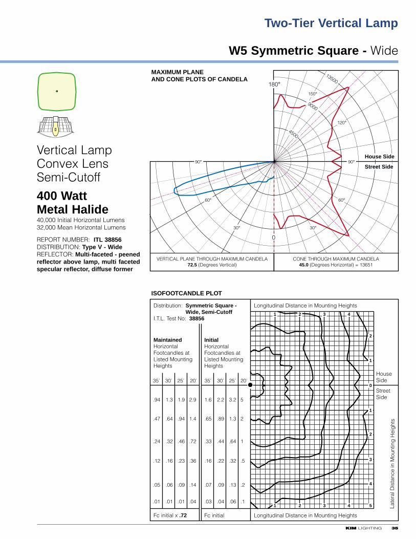
KKIIMM LIGHTING 3355
W5 Symmetric Square - Wide
Two-Tier Vertical Lamp
35' 30' 25' 20'35' 30' 25' 20'
MaintainedHorizontalFootcandles atListed MountingHeights
InitialHorizontalFootcandles atListed MountingHeights
1.6
.65
.33
.16
.07
.03
2.2
.89
.44
.22
.09
.04
3.2
1.3
.64
.32
.13
.06
5
2
1
.5
.2
.1
.94
.47
.24
.12
.05
.01
1.3
.64
.32
.16
.06
.01
1.9
.94
.46
.23
.09
.01
2.9
1.4
.72
.36
.14
.04
Distribution: Symmetric Square -Wide, Semi-Cutoff
I.T.L. Test No: 38856
Fc initial x .72
VERTICAL PLANE THROUGH MAXIMUM CANDELA72.5 (Degrees Vertical)
CONE THROUGH MAXIMUM CANDELA45.0 (Degrees Horizontal) = 13651
Fc initial
HouseSide
StreetSide
Longitudinal Distance in Mounting Heights
Late
ral D
ista
nce
in M
ount
ing
Hei
ght
s
Longitudinal Distance in Mounting Heights
ISOFOOTCANDLE PLOT
1
1
2
2
3
3
4
4
2
0
1
1
2
3
4
5
MAXIMUM PLANE AND CONE PLOTS OF CANDELA
House Side
Street Side
0
180°
30°
60°
90°
30°
60°
90°
4500
9000
13500
150°
120°
Vertical LampConvex LensSemi-Cutoff
400 WattMetal Halide40,000 Initial Horizontal Lumens32,000 Mean Horizontal Lumens
REPORT NUMBER: ITL 38856DISTRIBUTION: Type V - WideREFLECTOR: Multi-faceted - peenedreflector above lamp, multi facetedspecular reflector, diffuse former
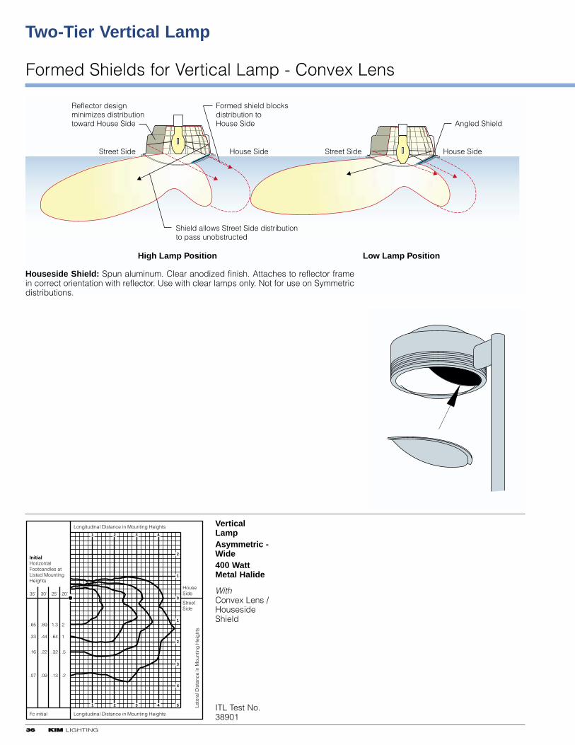
3366 KKIIMM LIGHTING
Two-Tier Vertical Lamp
Formed Shields for Vertical Lamp - Convex Lens
High Lamp Position
Angled Shield
Street Side House Side
Low Lamp Position
Formed shield blocksdistribution toHouse Side
Street Side House Side
Shield allows Street Side distributionto pass unobstructed
Reflector designminimizes distributiontoward House Side
Houseside Shield: Spun aluminum. Clear anodized finish. Attaches to reflector framein correct orientation with reflector. Use with clear lamps only. Not for use on Symmetricdistributions.
35' 30' 25' 20'
InitialHorizontalFootcandles atListed MountingHeights
.65
.33
.16
.07
.89
.44
.22
.09
1.3
.64
.32
.13
2
1
.5
.2
Fc initial
HouseSide
StreetSide
Longitudinal Distance in Mounting Heights
Late
ral D
ista
nce
in M
ount
ing
Hei
ght
s
Longitudinal Distance in Mounting Heights
1
1
2
2
3
3
4
4
2
0
1
1
2
3
4
5
VerticalLampAsymmetric - Wide400 WattMetal Halide
WithConvex Lens /HousesideShield
ITL Test No.38901
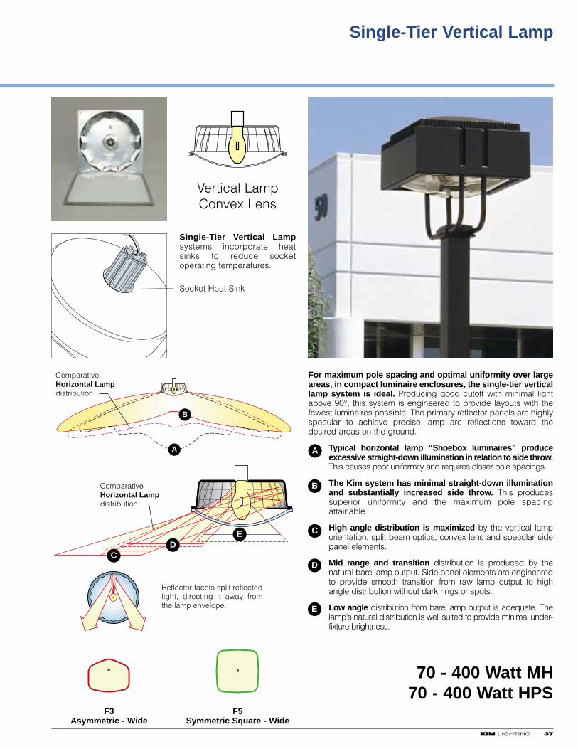
KKIIMM LIGHTING 3377
Single-Tier Vertical Lamp
Single-Tier Vertical Lampsystems incorporate heatsinks to reduce socketoperating temperatures.
Socket Heat Sink
For maximum pole spacing and optimal uniformity over largeareas, in compact luminaire enclosures, the single-tier verticallamp system is ideal. Producing good cutoff with minimal lightabove 90°, this system is engineered to provide layouts with thefewest luminaires possible. The primary reflector panels are highlyspecular to achieve precise lamp arc reflections toward thedesired areas on the ground.
Typical horizontal lamp “Shoebox luminaires” produceexcessive straight-down illumination in relation to side throw.This causes poor uniformity and requires closer pole spacings.
The Kim system has minimal straight-down illuminationand substantially increased side throw. This producessuperior uniformity and the maximum pole spacingattainable.
High angle distribution is maximized by the vertical lamporientation, split beam optics, convex lens and specular sidepanel elements.
Mid range and transition distribution is produced by thenatural bare lamp output. Side panel elements are engineeredto provide smooth transition from raw lamp output to highangle distribution without dark rings or spots.
Low angle distribution from bare lamp output is adequate. Thelamp's natural distribution is well suited to provide minimal under-fixture brightness.
A
ComparativeHorizontal Lampdistribution
B
ComparativeHorizontal Lampdistribution
C
ED
F3Asymmetric - Wide
F5Symmetric Square - Wide
70 - 400 Watt MH70 - 400 Watt HPS
A
B
C
D
E
Reflector facets split reflected light, directing it away from the lamp envelope.
Vertical LampConvex Lens

Single-Tier Vertical Lamp
F3 Asymmetric
3388 KKIIMM LIGHTING
35' 30' 25' 20'35' 30' 25' 20'
MaintainedHorizontalFootcandles atListed MountingHeights
InitialHorizontalFootcandles atListed MountingHeights
1.5
.73
.37
.15
.07
.04
2.0
1.0
.5
.2
.1
.05
2.9
1.4
.72
.29
.14
.07
4.5
2.3
1.1
.45
.23
.11
1.1
.53
.26
.11
.05
.03
1.4
.72
.36
.14
.07
.04
2.0
1.0
.52
.21
.1
.05
3.2
1.6
.81
.32
.16
.08
Distribution: Asymmetric - Wide,Semi-Cutoff
I.T.L. Test No: 44887
Fc initial x .72
VERTICAL PLANE THROUGH MAXIMUM CANDELA74.0 (Degrees Vertical)
CONE THROUGH MAXIMUM CANDELA50.3 (Degrees Horizontal) = 10090
Fc initial
HouseSide
StreetSide
Longitudinal Distance in Mounting Heights
Late
ral D
ista
nce
in M
ount
ing
Hei
ght
s
Longitudinal Distance in Mounting Heights
ISOFOOTCANDLE PLOT
1
1
2
2
3
3
4
4
2
0
1
1
2
3
4
5
MAXIMUM PLANE AND CONE PLOTS OF CANDELA
House Side
Street Side
0
180°
30°
60°
90°
30°
60°
90°
3300
6600
9900
150°
120°
Vertical LampConvex LensSemi-Cutoff
400 WattMetal Halide40,000 Initial Horizontal Lumens32,000 Mean Horizontal Lumens
REPORT NUMBER: ITL 44887DISTRIBUTION: Type III - WideREFLECTOR: Multi-faceted - peenedreflector above lamp, multi facetedspecular reflector, diffuse former
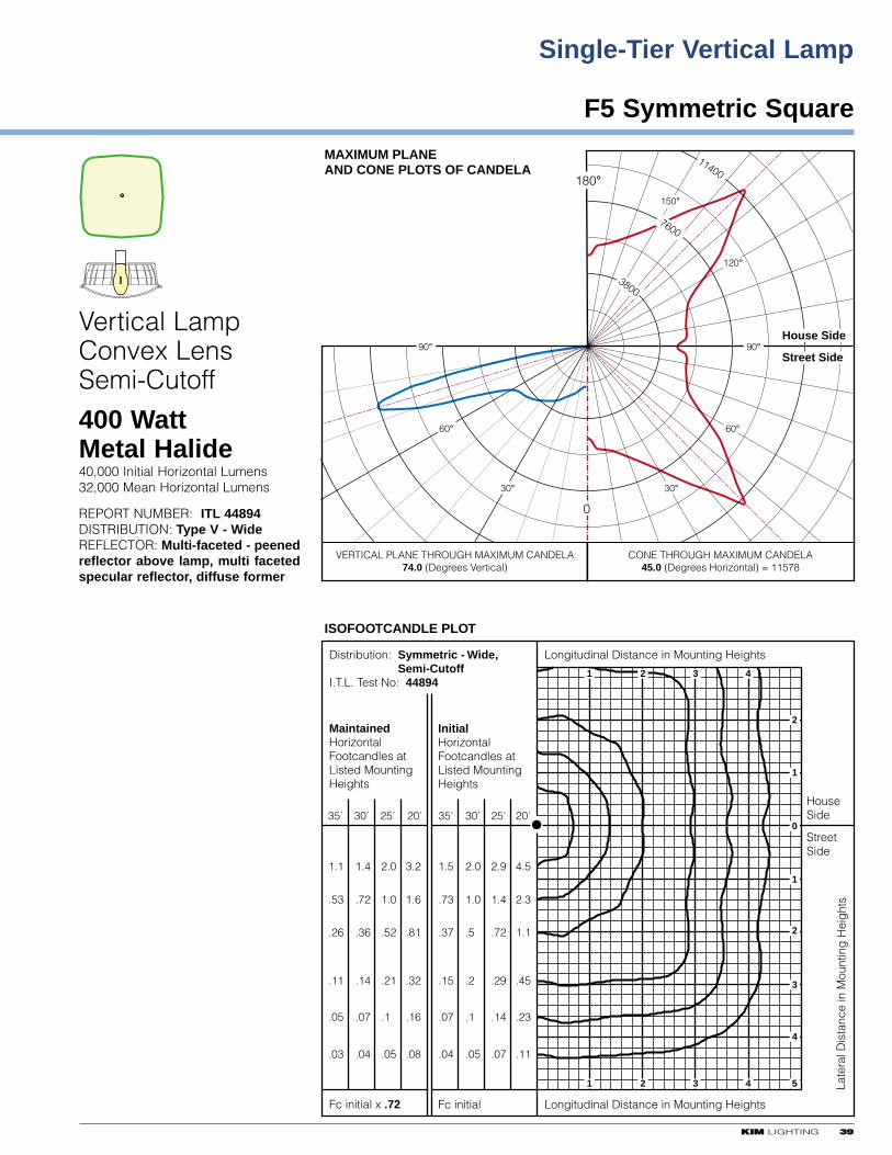
KKIIMM LIGHTING 3399
F5 Symmetric Square
Single-Tier Vertical Lamp
35' 30' 25' 20'35' 30' 25' 20'
MaintainedHorizontalFootcandles atListed MountingHeights
InitialHorizontalFootcandles atListed MountingHeights
1.5
.73
.37
.15
.07
.04
2.0
1.0
.5
.2
.1
.05
2.9
1.4
.72
.29
.14
.07
4.5
2.3
1.1
.45
.23
.11
1.1
.53
.26
.11
.05
.03
1.4
.72
.36
.14
.07
.04
2.0
1.0
.52
.21
.1
.05
3.2
1.6
.81
.32
.16
.08
Distribution: Symmetric - Wide,Semi-Cutoff
I.T.L. Test No: 44894
Fc initial x .72
VERTICAL PLANE THROUGH MAXIMUM CANDELA74.0 (Degrees Vertical)
CONE THROUGH MAXIMUM CANDELA45.0 (Degrees Horizontal) = 11578
Fc initial
HouseSide
StreetSide
Longitudinal Distance in Mounting Heights
Late
ral D
ista
nce
in M
ount
ing
Hei
ght
s
Longitudinal Distance in Mounting Heights
ISOFOOTCANDLE PLOT
1
1
2
2
3
3
4
4
2
0
1
1
2
3
4
5
MAXIMUM PLANE AND CONE PLOTS OF CANDELA
House Side
Street Side
0
180°
30°
60°
90°
30°
60°
90°
3800
7600
11400
150°
120°
Vertical LampConvex LensSemi-Cutoff
400 WattMetal Halide40,000 Initial Horizontal Lumens32,000 Mean Horizontal Lumens
REPORT NUMBER: ITL 44894DISTRIBUTION: Type V - WideREFLECTOR: Multi-faceted - peenedreflector above lamp, multi facetedspecular reflector, diffuse former
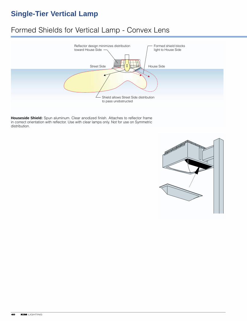
Single-Tier Vertical Lamp
Formed Shields for Vertical Lamp - Convex Lens
4400 KKIIMM LIGHTING
Street Side House Side
Formed shield blockslight to House Side
Reflector design minimizes distributiontoward House Side
Shield allows Street Side distributionto pass unobstructed
Houseside Shield: Spun aluminum. Clear anodized finish. Attaches to reflector framein correct orientation with reflector. Use with clear lamps only. Not for use on Symmetricdistribution.
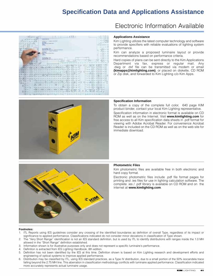
KKIIMM LIGHTING 4411
Electronic Information Available
Specification Data and Applications Assistance
Applications AssistanceKim Lighting utilizes the latest computer technology and softwareto provide specifiers with reliable evaluations of lighting systemperformance.Kim can analyze a proposed luminaire layout or providerecommendations based on performance criteria.Hard copies of plans can be sent directly to the Kim ApplicationsDepartment via fax, express or regular mail. Any .dwg or .dxf file can be transmitted via modem or email([email protected]), or placed on diskette, CD ROMor Zip disk, and forwarded to Kim Lighting c/o Kim Apps.
Footnotes:1. ITL Reports using IES guidelines consider any crossing of the identified boundaries as definition of overall Type, regardless of its impact or
significance to applied performance. Classifications indicated do not consider minor deviations in classification of Type shown.2. The “Very Short Range” identification is not an IES standard definition, but is used by ITL to identify distributions with ranges inside the 1.0 MH
allowed in the “Short Range” definition established.3. Information shown is for illustrative purposes only and does not represent a specific luminaire's performance.4. Definition is extracted from IES Lighting Handbook, 8th edition.5. Definition has not been identified by the IES at this time. Definition shown is based on Kim Lighting research and development efforts and
engineering of optical systems to improve applied performance.6. Distribution may be classified by ITL, using IES standard practices, as a Type IV distribution, due to a small portion of the 50% isocandela trace
falling beyond the 2.75 MH line. This aberration in classification methodology conflicts with luminaire applied performance. Classification indicatedmore accurately represents actual luminaire usage.
Photometric FilesKim photometric files are available free in both electronic andhard copy format.Electronic photometric files include .pdf file format pages forprinting and .ies files for use in lighting calculation software. Thecomplete .ies / .pdf library is available on CD ROM and on theinternet at www.kimlighting.com.
Specification InformationTo obtain a copy of the complete full color, 640 page KIMproduct binder, contact your local Kim Lighting representative.Specification information in electronic format is available on CDROM as well as on the Internet. Visit www.kimlighting.com forfree access to all Kim specification data sheets in .pdf format forviewing with Adobe Acrobat Reader. For convenience AcrobatReader is included on the CD ROM as well as on the web site forimmediate download.