Embed Size (px)
DESCRIPTION
Power Supplies
Citation preview

Siemens FI 01 · 2010 US Edition
7/2 Product overview
Isolating power supplies with HART7/3 SITRANS I100
Output isolators with HART7/6 SITRANS I200
You can download all instructions, cata-logs and certificates for SITRANS I free of charge at the following Internet ad-dress:www.siemens.com/sitransi
SITRANS IIsolating power suppliesand output isolators
© Siemens AG 2010

Isolating power supplies and output isolatorsProduct overview
7/2 Siemens FI 01 · 2010 US Edition
7
■ Overview
Area of application Description Catalog page
SITRANS I100 isolating power supply
Isolating power supply for supplying 2- and 3-wire transmitters and for connecting mA sources in the hazardous area
SITRANS I100Isolating power supply with HART for rail mounting, with intrinsically-safe input.
7/3
SITRANS I200 output isolator
Output isolator for controlling valve positioners, i/p converters or indicators in the hazardous area
SITRANS I200Output isolator with HART for rail mounting, with intrinsically-safe output
7/6
© Siemens AG 2010

Isolating power supplies and output isolatorsIsolating power supplies with HART
SITRANS I100
7/3Siemens FI 01 · 2010 US Edition
7
■ Overview
Analog input 0/4 ... 20 mA
The isolating power supplies are used for the intrinsically safe operation of 2- and 3-wire transmitters and for connecting to in-trinsically safe mA sources.
The 2- and 3-wire transmitters are supplied with auxiliary power from the transmitter supply unit.
For 2-wire transmitters the isolators transfer the HART communi-cation signal bidirectionally.
■ Benefits
• Active output 0/4 ... 20 mA• Suitable for 2-, 3-wire transmitters, 2-wire HART transmitters
and mA sources• Intrinsically safe input [Ex ia] IIC• Galvanic isolation between input, output and auxiliary power• Open-circuit and short-circuit monitoring and messaging for
input and output (can be switched off)• Installation possible in Zone 2 and Div. 2• Can be used up to SIL 2 (IEC 61508)
■ Design
The HART isolating power supply is comprised of a compact plastic enclosure (IP30) and is equipped with push-in screw terminals.
On the front are a green LED for indicating the power supplystatus and a red LED for signaling errors.
The auxiliary power supply can be connected individually using push-in screw terminals or jointly for up to 40 units using pac-Bus.
SITRANS I100 isolating power supply, function block diagram
■ Technical specifications
Zones
0 1 2 20 21 22
Ex i interfaces X X X X X X
Installation in X X
SITRANS I100 Isolating Power Supplies with HART
Ex i input
Input signal 0/4 ... 20 mA with HART
Functional range 0 ... 24 mA
Max. input current for mA sources 50 mA
Transmitter supply voltage ≥ 16 V at 20 mA (for 2-, 3-wire)
Supply voltage residual ripple ≤ 25 mVeff
No-load voltage ≤ 26 V
Short-circuit current ≤ 35 mA
Input resistance (AC impedance HART)
≈ 500 Ω
Input resistance for mA sources 30 Ω
Communication signal (on 2-wire transmitters)
Bidirectional HART transmission, 0.5 kHz ... 30 kHz
Output
Output signal 0/4 ... 20 mA with HART
Load resistance RL 0 ... 600 W (terminal 1+/2-)0 ... 379 W (terminal 3+/2-)(with internal 221 W resistance for HART)
Residual ripple ≤ 40 μAeff
No-load voltage ≤ 15,5 V
Communication signal Bidirectional HART transmission, 0.5 kHz ... 30 kHz
Response time (10 % ... 90 %) ≤ 25 ms
Transfer behaviorInput/Output
1:1(0 ... 20 mA --> 0 ... 20 mA,4 ... 20 mA --> 4 ... 20 mA)
Measuring accuracyAccuracy, typical data expressed as % of calibrated span at UN, 23 °C
Linearity error ≤ 0,1 %
Offset error ≤ 0,1 %
Temperature influence ≤ 0,1 %/10 K
Power supply effect within voltage range
≤ 0,01 %
Load resistance effect ≤ 0,02 %
Analoginput
4 ... 20 mAEx i
© Siemens AG 2010
Isolating power supplies and output isolatorsIsolating power supplies with HART
SITRANS I100
7/4 Siemens FI 01 · 2010 US Edition
7
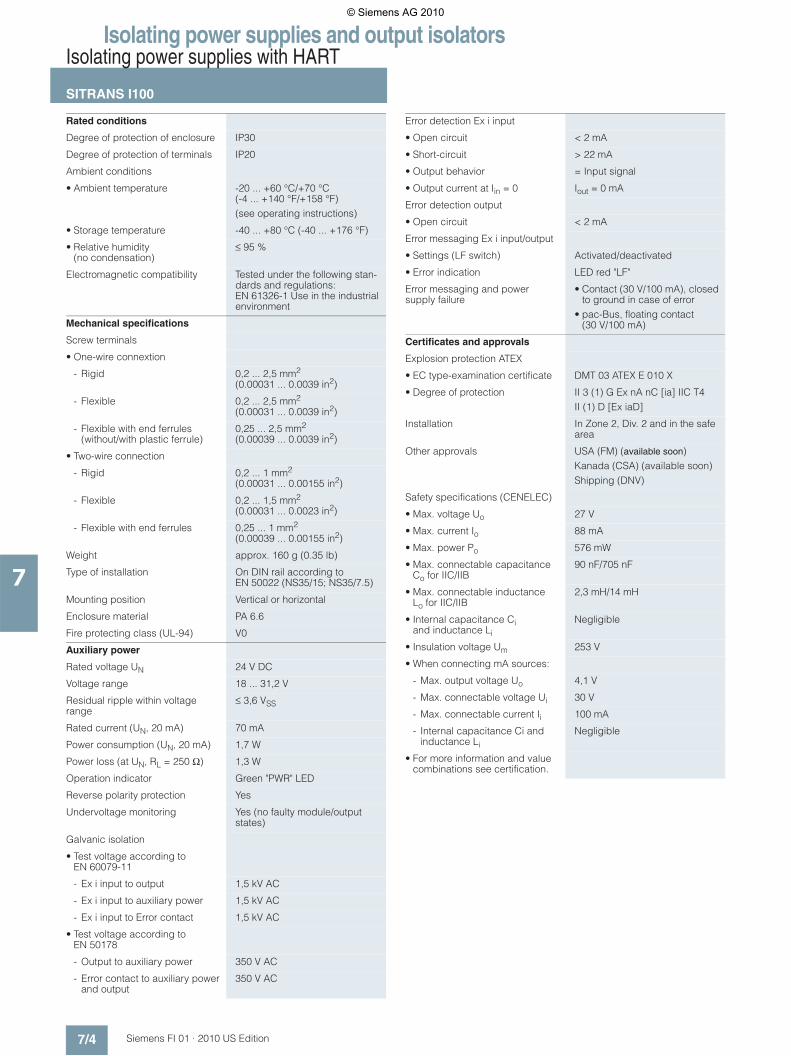
Rated conditions
Degree of protection of enclosure IP30
Degree of protection of terminals IP20
Ambient conditions
• Ambient temperature -20 ... +60 °C/+70 °C (-4 ... +140 °F/+158 °F)(see operating instructions)
• Storage temperature -40 ... +80 °C (-40 ... +176 °F)
• Relative humidity (no condensation)
≤ 95 %
Electromagnetic compatibility Tested under the following stan-dards and regulations: EN 61326-1 Use in the industrial environment
Mechanical specifications
Screw terminals
• One-wire connextion
- Rigid 0,2 ... 2,5 mm2 (0.00031 ... 0.0039 in2)
- Flexible 0,2 ... 2,5 mm2 (0.00031 ... 0.0039 in2)
- Flexible with end ferrules (without/with plastic ferrule)
0,25 ... 2,5 mm2 (0.00039 ... 0.0039 in2)
• Two-wire connection
- Rigid 0,2 ... 1 mm2 (0.00031 ... 0.00155 in2)
- Flexible 0,2 ... 1,5 mm2 (0.00031 ... 0.0023 in2)
- Flexible with end ferrules 0,25 ... 1 mm2 (0.00039 ... 0.00155 in2)
Weight approx. 160 g (0.35 lb)
Type of installation On DIN rail according to EN 50022 (NS35/15; NS35/7.5)
Mounting position Vertical or horizontal
Enclosure material PA 6.6
Fire protecting class (UL-94) V0
Auxiliary power
Rated voltage UN 24 V DC
Voltage range 18 ... 31,2 V
Residual ripple within voltage range
≤ 3,6 VSS
Rated current (UN, 20 mA) 70 mA
Power consumption (UN, 20 mA) 1,7 W
Power loss (at UN, RL = 250 Ω) 1,3 W
Operation indicator Green "PWR" LED
Reverse polarity protection Yes
Undervoltage monitoring Yes (no faulty module/output states)
Galvanic isolation
• Test voltage according to EN 60079-11
- Ex i input to output 1,5 kV AC
- Ex i input to auxiliary power 1,5 kV AC
- Ex i input to Error contact 1,5 kV AC
• Test voltage according to EN 50178
- Output to auxiliary power 350 V AC
- Error contact to auxiliary power and output
350 V AC
Error detection Ex i input
• Open circuit < 2 mA
• Short-circuit > 22 mA
• Output behavior = Input signal
• Output current at Iin = 0 Iout = 0 mA
Error detection output
• Open circuit < 2 mA
Error messaging Ex i input/output
• Settings (LF switch) Activated/deactivated
• Error indication LED red "LF"
Error messaging and power supply failure
• Contact (30 V/100 mA), closed to ground in case of error
• pac-Bus, floating contact (30 V/100 mA)
Certificates and approvals
Explosion protection ATEX
• EC type-examination certificate DMT 03 ATEX E 010 X
• Degree of protection II 3 (1) G Ex nA nC [ia] IIC T4II (1) D [Ex iaD]
Installation In Zone 2, Div. 2 and in the safe area
Other approvals USA (FM) (available soon)Kanada (CSA) (available soon)Shipping (DNV)
Safety specifications (CENELEC)
• Max. voltage Uo 27 V
• Max. current Io 88 mA
• Max. power Po 576 mW
• Max. connectable capacitance Co for IIC/IIB
90 nF/705 nF
• Max. connectable inductance Lo for IIC/IIB
2,3 mH/14 mH
• Internal capacitance Ci and inductance Li
Negligible
• Insulation voltage Um 253 V
• When connecting mA sources:
- Max. output voltage Uo 4,1 V
- Max. connectable voltage Ui 30 V
- Max. connectable current Ii 100 mA
- Internal capacitance Ci and inductance Li
Negligible
• For more information and value combinations see certification.
© Siemens AG 2010

Isolating power supplies and output isolatorsIsolating power supplies with HART
SITRANS I100
7/5Siemens FI 01 · 2010 US Edition
7
■ Selection and Ordering data
} Available ex stock.
■ Dimensional drawings
SITRANS I100 isolating power supply with HART, dimensions in mm (inch)
■ Schematics
SITRANS I100 isolating power supply with HART, connection diagram
SITRANS I100 isolating power supply with HART, output configuration
Order No.
SITRANS I100 Isolating Power Supply with HART
} 7NG4124-0AA00
For rail mounting, for supplying 2-/3-wire transmitters and for mA sources, output 0/4 ... 20 mA, with intrinsically safe input
Accessories
pac-Bus basic setWith 5 single elements and 1 ter-minal set (beginning and end)
} 7NG4998-1AA
pac-Bus extension setWith 5 single elements
} 7NG4998-1AB
122
(4.8
)
5 (4
.5)
,411
108 (4.25)
99 (3.9)17,6(0.7)
pac-Bus Division 2Zone 2
Safe areaHazardous area
Division 1Zone 0/1
Field device SPS / PCSSITRANS I100
IP
11-10
221 W
1+2-
7+8
3+
9-LF 24 V DC
-
24 V- +LF
112+
RL+-
© Siemens AG 2010
Isolating power supplies and output isolatorsOutput isolators with HART
SITRANS I200
7/6 Siemens FI 01 · 2010 US Edition
7
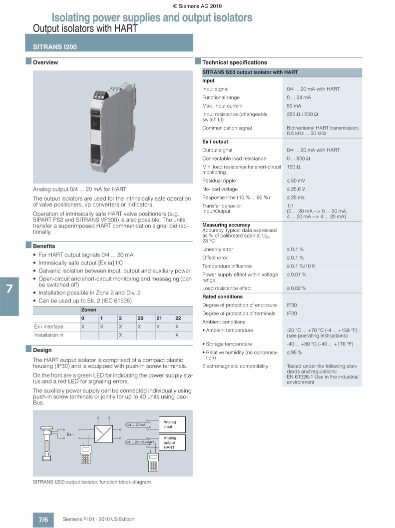
■ Overview
Analog output 0/4 ... 20 mA for HART
The output isolators are used for the intrinsically safe operation of valve positioners, i/p converters or indicators.
Operation of intrinsically safe HART valve positioners (e.g. SIPART PS2 and SITRANS VP300) is also possible. The units transfer a superimposed HART communication signal bidirec-tionally.
■ Benefits
• For HART output signals 0/4 ... 20 mA• Intrinsically safe output [Ex ia] IIC• Galvanic isolation between input, output and auxiliary power• Open-circuit and short-circuit monitoring and messaging (can
be switched off)• Installation possible in Zone 2 and Div. 2• Can be used up to SIL 2 (IEC 61508)
■ Design
The HART output isolator is comprised of a compact plastic housing (IP30) and is equipped with push-in screw terminals.
On the front are a green LED for indicating the power supply sta-tus and a red LED for signaling errors.
The auxiliary power supply can be connected individually using push-in screw terminals or jointly for up to 40 units using pac-Bus.
SITRANS I200 output isolator, function block diagram
■ Technical specifications
Zonen
0 1 2 20 21 22
Ex i interface X X X X X X
Installation in X X
Analoginput
Analogoutput HART
0/4 ... 20 mA
0/4 ... 20 mA HART
Ex i
SITRANS I200 output isolator with HART
Input
Input signal 0/4 ... 20 mA with HART
Functional range 0 ... 24 mA
Max. input current 50 mA
Input resistance (changeable switch LI)
225 Ω / 550 Ω
Communication signal Bidirectional HART transmission, 0.5 kHz ... 30 kHz
Ex i output
Output signal 0/4 ... 20 mA with HART
Connectable load resistance 0 ... 800 Ω
Min. load resistance for short-circuit monitoring
150 Ω
Residual ripple ≤ 50 mV
No-load voltage ≤ 25,6 V
Response time (10 % ... 90 %) ≤ 25 ms
Transfer behaviorInput/Output
1:1(0 ... 20 mA --> 0 ... 20 mA,4 ... 20 mA --> 4 ... 20 mA)
Measuring accuracyAccuracy, typical data expressed as % of calibrated span at UN, 23 °C
Linearity error ≤ 0,1 %
Offset error ≤ 0,1 %
Temperature influence ≤ 0,1 %/10 K
Power supply effect within voltage range
≤ 0,01 %
Load resistance effect ≤ 0,02 %
Rated conditions
Degree of protection of enclosure IP30
Degree of protection of terminals IP20
Ambient conditions
• Ambient temperature -20 °C ... +70 °C (-4 ... +158 °F) (see poerating instructions)
• Storage temperature -40 ... +80 °C (-40 ... +176 °F)
• Relative humidity (no condensa-tion)
≤ 95 %
Electromagnetic compatibility Tested under the following stan-dards and regulations: EN 61326-1 Use in the industrial environment
© Siemens AG 2010

Isolating power supplies and output isolatorsOutput isolators with HART
SITRANS I200
7/7Siemens FI 01 · 2010 US Edition
7
■ Selection and Ordering data
} Available ex stock.
Mechanical specification
Screw terminals
• One-wire connection
- Rigid 0,2 ... 2,5 mm2 (0.00031 ... 0.0039 in2)
- Flexible 0,2 ... 2,5 mm2 (0.00031 ... 0.0039 in2)
- Flexible with end ferrules (without/with plastic ferrule)
0,25 ... 2,5 mm2 (0.00039 ... 0.0039 in2)
• Two-wire connection
- Rigid 0,2 ... 1 mm2 (0.00031 ... 0.00155 in2)
- Flexible 0,2 ... 1,5 mm2 (0.00031 ... 0.0023 in2)
- Flexible with end ferrules 0,25 ... 1 mm2 (0.00039 ... 0.00155 in2)
Weight Approx. 160 g (0.35 lb)
Type of installation On DIN rail according to EN 50022 (NS35/15; NS35/7.5)
Mounting position Vertical or horizontal
Enclosure material PA 6.6
Fire protecting class (UL-94) V0
Auxiliary power
Rated voltage UN 24 V DC
Voltage range 18 ... 31,2 V
Residual ripple within voltage range
≤ 3,6 VSS
Rated current (UN, 20 mA) 80 mA
Power consumption (UN, 20 mA) 1,3 W
Power loss (at UN, RL = 500 Ω) 1,1 W
Operation indicator Green "PWR" LED
Reverse polarity protection Yes
Undervoltage monitoring Yes (no faulty module/output states)
Galvanic isolation
• Test voltage according to EN 60079-11
- Ex i output to input 1,5 kV AC
- Ex i output to auxiliary power 1,5 kV AC
- Error contact to Ex i output 1,5 kV AC
• Test voltage according to EN 50178
- Input to auxiliary power 350 V AC
- Error contact to auxiliary power and input
350 V AC
Error detection Ex i output
• Open circuit > 10 kΩ
• Short-circuit < 15 Ω
• Input behavior > 6 kΩ
• Open-circuit detection only for input current
≥ 3,6 mA
• Settings (LF switch) Activated/deactivated
• Error indication LED red "LF"
• Error messaging and power supply failure
• Contact (30 V/100 mA), closed to ground in case of error
• pac-Bus, floating contact (30 V/100 mA)
Certificates and approvals
Explosion protection ATEX
• EC type-examination certificate DMT 03 ATEX E 012 X
• Degree of protection II 3 (1) G Ex nA nC [ia] IIC T4II (1) D [Ex iaD]
Installation In Zone 2, Div. 2 and in the safe area
Other approvals USA (FM) (available soon)Canada (CSA) (available soon)Shipping (DNV)
Safety specifications (CENELEC)
• Max. voltage Uo 25,6 V
• Max. current Io 96 mA
• Max. power Po 605 mW
• Max. connectable capacitance Co for IIC/IIB
103 nF/800 nF
• Max. connectable inductance Lo for IIC/IIB
1,9 mH/11 mH
• Internal capacitance Ci and induc-tance Li
Negligible
• Insulation voltage Um 253 V
• For more information and value combinations see certification.
Order No.
SITRANS I200 output isolator with HART
} 7NG4131-0AA00
For rail mounting, input 0/4 ... 20 mA, output 0/4 ... 20 mA, intrinsically safe
Accessories
pac-Bus basic setWith 5 single elements and 1 terminal set (beginning and end)
} 7NG4998-1AA
pac-Bus extension setWith 5 single elements
} 7NG4998-1AB
© Siemens AG 2010

Isolating power supplies and output isolatorsOutput isolators with HART
SITRANS I200
7/8 Siemens FI 01 · 2010 US Edition
7
■ Dimensional drawings
SITRANS I200 output isolator with HART, dimensions in mm (inch)
■ Schematics
SITRANS I200 output isolator with HART, connection diagram
7
122
(4.8
)
5 (4
.5)
,411
108 (4.25)
99 (3.9)17,6(0.7)
pac-Bus Division 2Zone 2
Safe areaHazardous area
Division 1Zone 0/1
Field device SPS/PCSSITRANS I200
IP
11-
10+
LI1
1
7+8
2
+
9-
-
LF+
24 V DC-
24 V- +LF
© Siemens AG 2010