Embed Size (px)
Citation preview
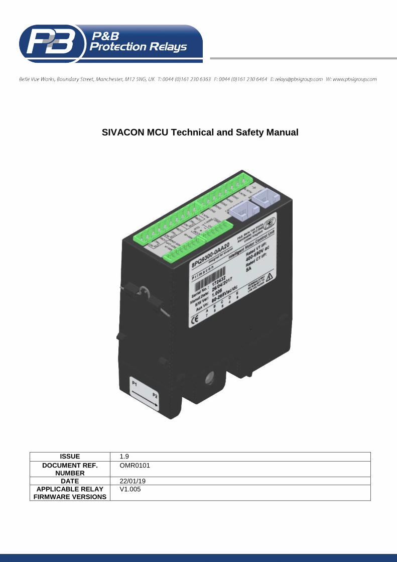
SIVACON MCU Technical and Safety Manual
ISSUE 1.9
DOCUMENT REF. NUMBER
OMR0101
DATE 22/01/19
APPLICABLE RELAY FIRMWARE VERSIONS
V1.005
SIVACON MCU Technical Manual Document Ref. OMR0101
Issue 1.9, 2019
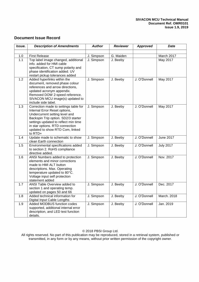
Document Issue Record
Issue. Description of Amendments Author Reviewer Approved Date
1.0 First Release J. Simpson G. Maiden March 2017
1.1 Top label image changed, additional info. added for HMI cable specification, CT sump polarity and phase identification added. UV restart pickup tolerances added
J. Simpson J. Beeby May 2017
1.2 Added hyperlinks within the document, removed phase colour references and arrow directions, updated acronym appendix. Removed DOW 2-speed reference. SIVACON MCU image(s) updated to include side label.
J. Simpson J. Beeby J. O’Donnell May 2017
1.3 Correction made to settings table for Internal Error Reset options, Undercurrent setting level and Backspin Trip option. SD2/3 starter settings updated to reflect min time in star options. RTD connection updated to show RTD Com, linked to RTD+
J. Simpson J. Beeby J. O’Donnell May 2017
1.4 Update made to schematic to show clean Earth connection
J. Simpson J. Beeby J. O’Donnell June 2017
1.5 Environmental specifications added to section 2. RoHS compliance directive added.
J. Simpson J. Beeby J. O’Donnell July 2017
1.6 ANSI Numbers added to protection elements and minor corrections made to HMI ALT button descriptions. Max. Operating temperature updated to 80°C. Voltage input self protection statement added
J. Simpson J. Beeby J. O’Donnell Nov. 2017
1.7 ANSI Table Overview added to section 1 and operating temp. updated on pages 50 and 66
J. Simpson J. Beeby J. O’Donnell Dec. 2017
1.8 Added technical information for Digital Input Cable Lengths
J. Simpson J. Beeby J. O’Donnell March. 2018
1.9 Added MODBUS function codes supported, additional internal error description, and LED test function details.
J. Simpson J. Beeby J. O’Donnell Jan. 2019
© 2018 PBSI Group Ltd.
All rights reserved. No part of this publication may be reproduced, stored in a retrieval system, published or transmitted, in any form or by any means, without prior written permission of the copyright owner.
Page 1
SIVACON MCU Technical Manual Document Ref. OMR0101
Issue 1.9, 2019
Contents
1. SIVACON MCU ........................................................................................................................ 3
Part Numbers and Component Details ...................................................................................... 3
1.1. Protective Functions. .......................................................................................................... 4 1.2. SIVACON MCU ANSI Device Numbers ............................................................................. 4 1.3. Engineering Data. ............................................................................................................... 5 1.4. HMI Panel ........................................................................................................................... 5 1.5. Starting Logic. .................................................................................................................... 6
1.6. Control Functions. .............................................................................................................. 6
1.7. Control Output Relays. ....................................................................................................... 7 1.8. Control Inputs. .................................................................................................................... 7
2. Technical Specification. ......................................................................................................... 8 3. SIVACON MCU TypeTests / Certification ............................................................................ 10 4. Analogue Inputs. ................................................................................................................... 11
4.1. Power Supply Live. ........................................................................................................... 11
4.2. Voltage Reference Inputs. ................................................................................................ 11
4.3. Current Sensor Inputs. ..................................................................................................... 11
4.4. Temperature Input(s). ....................................................................................................... 11 5. Control Outputs. ................................................................................................................... 12
5.1. Output Relays. .................................................................................................................. 12
5.2. Relay Settings. ................................................................................................................. 12
6. Control Inputs. ...................................................................................................................... 15 7. Serial Ports. ........................................................................................................................... 17
7.1. RS485 .............................................................................................................................. 17
7.2. Dual RS485 ...................................................................................................................... 17 7.3. RS232/HMI Interface ........................................................................................................ 17
8. SIVACON MCU HMI Operator Panel Functions. ................................................................. 18 8.1. HMI Pushbutton Functions ............................................................................................... 18 8.2. HMI LED Configuration ..................................................................................................... 19
8.3. Programming Communication Bus Address using HMI Operator Panel ........................... 19 9. Setting Sheets ....................................................................................................................... 20
9.1. SIVACON MCU System Settings Summary. .................................................................... 20 9.2. SIVACON MCU Control Setting Summary. ...................................................................... 21
9.3. Start & Stop Source configuration .................................................................................... 21 9.4. SIVACON MCU Protection Setting Summary. .................................................................. 22 9.5. SIVACON MCU Blank Protection Setting Summary. ........................................................ 23
10. Serial Settings. .................................................................................................................... 24 11. Motor Settings. .................................................................................................................... 26
12. Starting Methods. ................................................................................................................ 27 13. Starter Settings. .................................................................................................................. 30
14. Additional Starter Settings. ................................................................................................ 33 15. Protection Settings. ............................................................................................................ 34
15.1. Protection Functions. ...................................................................................................... 35
15.1.1. Maximum Start Time (ANSI 48/14) .......................................................................... 35 15.1.2. Thermal Model (ANSI 26/49) ................................................................................... 35
15.1.3. Undercurrent (ANSI 37) ........................................................................................... 37 15.1.4. Overcurrent (ANSI 50/51) ........................................................................................ 38 15.1.5. Single Phase (ANSI 46SP) ...................................................................................... 38 15.1.6. Unbalance Current (ANSI 46) .................................................................................. 39
Page 2
SIVACON MCU Technical Manual Document Ref. OMR0101
Issue 1.9, 2019
15.1.7. Undervoltage (ANSI 27) ........................................................................................... 40 15.1.8. U/V Lockout (ANSI 27/86) ........................................................................................ 40 15.1.9. Earth Fault (ANSI 50n/51n) ...................................................................................... 41 15.1.10. Over Temperature (ANSI 38/49) ............................................................................ 41
15.1.11. Too Many Starts (ANSI 66) .................................................................................... 42 15.1.12. Overvoltage (ANSI 59) ........................................................................................... 42 15.1.13. External 1 to 5 (ANSI 36) ....................................................................................... 42 15.1.14. Short Circuit (ANSI 50) .......................................................................................... 43 15.1.15. Contactor Fault (ANSI 48) ...................................................................................... 43
15.1.16. Phase Rotation (ANSI 47) ...................................................................................... 43
15.1.17. Back Spin (ANSI 86) .............................................................................................. 44 15.1.18. Serial Timeout (ANSI 74) ....................................................................................... 44
15.1.19. Serial Inhibit. .......................................................................................................... 44 15.1.20. Internal Error. ......................................................................................................... 44
16. System Settings. ................................................................................................................. 47 17. External Memory Storage (1-Wire Interface). .................................................................... 48
17.1. Programming the 1-Wire Interface. ................................................................................. 49 17.2. 1-Wire Interface Communication Status and Programming Commands ........................ 50
Appendix 1 ................................................................................................................................. 52 SIVACON MCU Installation – Main Unit .................................................................... 52 SIVACON MCU Installation – HMI Unit ..................................................................... 53
SIVACON MCU Installation – 1 Wire Module ............................................................ 54
Appendix 2 ................................................................................................................................. 55 Termination Numbers. ............................................................................................... 55
Appendix 3 ................................................................................................................................. 59
SIVACON MCU Schematic Diagrams. ...................................................................... 59 Integrated CT Module Installation. ............................................................................ 60
Appendix 5 ................................................................................................................................. 61 Thermal Overload Trip Times. ................................................................................... 61
Appendix 6 ................................................................................................................................. 62 Fast Scan Values. ..................................................................................................... 62
Appendix 7 ................................................................................................................................. 63
SIVACON MCU Drive Number/Protocol Programming Module................................. 63 Appendix 8 ................................................................................................................................. 67
SIVACON MCU-CONTROL (SIVACON MCU Starter Control Module) ..................... 67 Appendix 9 ................................................................................................................................. 68
Installation and Maintenance..................................................................................... 68 Appendix 10 ............................................................................................................................... 71
General Abbreviation KEY ........................................................................................ 71 Appendix 11 ............................................................................................................................... 72
Handling Guidelines. ................................................................................................. 72
Appendix 12 ............................................................................................................................... 73 Order Form / Code Structure..................................................................................... 73

Page 3
SIVACON MCU Technical Manual Document Ref. OMR0101
Issue 1.9, 2019
1. SIVACON MCU
P&B Protection Relays SIVACON MCU Protection Relay is a highly-sophisticated microprocessor based motor protection and control unit, specifically designed to be used with 3-phase motors of full load currents below 29 Amps as an integral part of any type or manufacture of Motor Control Centres. Full load currents in excess of 29A can utilise an external CT module, which interfaces directly to the SIVACON MCU relay via a low power interface. The SIVACON MCU, due to its small size and innovative design, is able to fit in to the smallest of starter compartments. All of the features required to allow flexible control, protection and monitoring of motor starters either by direct hard wired inputs and / or via any of the available serial ports, which support 1ms time stamping of events embedded into the SIVACON MCU relay. The SIVACON MCU Protection Relay can be used to control Direct On Line, Star-Delta 2 & 3, Direct On Line Reversing, Two Speed, Air Circuit Breaker, DOL with Heater, DOL Reversing with Heater and Variable Speed Drive motor starters. The SIVACON MCU can also function in a no starter mode configuration, offering protection only based functions. The SIVACON MCU monitors the 3-phase current and voltage along with single channel RTD temperature measurement to provide a comprehensive motor protection package. This is combined with all the necessary control and monitoring functions and a high-speed communication facility. The unit is a small, easily installed package supplied at a very competitive cost which makes this device one of the most attractive Motor Protection and Control device available today. All hard-wired control inputs are connected to the device via optically isolated inputs to enable all starting, stopping and tripping commands to be carried out by the unit. The status of all individual hard-wired contacts is provided via any of the communication ports. An optional HMI panel can be connected to the SIVACON MCU relay to provide a basic operator control panel. All Setting parameters are programmed independently for each unit via any of the communication ports and PC based software package. Setting parameters can be programmed via SCADA/DCS systems using the MODBUS RTU protocol. The SIVACON MCU can be configured to support the majority of motor starter applications, protective functions can be individually configured to enable or disable the tripping and alarm functions. The HMI operator offers 12 x Tri-Colour Light Emitting Diodes mounted on the front plate, this can provide visual indication of the motor status i.e. ON / INHIBIT / OFF and ALARM / FAULTY / HEALTHY conditions, MOTOR LOAD and individual TRIP status. Flexible high speed control via PLC or DCS systems is obtained through the SIVACON MCU communication ports, allowing computer access to full control and monitoring of motor data, including: running data, motor statistical data and control input status. SIVACON MCU – Motor Control Unit designed for SIVACON
Part Numbers and Component Details
Part Number Description
8PQ9300-0AA20 SIVACON MCU Relay with integrated CT's 0.1A - 5A
8PQ9300-0AA21 SIVACON MCU Relay with integrated CT's 3A - 29A
8PQ9300-0AA22 SIVACON MCU Relay with terminal for external CT connection
8PQ9300-0AA16 SIVACON MCU Touch Panel (HMI operator panel)
8PQ9300-0AA26 SIVACON MCU Identification Module (1 Wire Memory Module)

Page 4
SIVACON MCU Technical Manual Document Ref. OMR0101
Issue 1.9, 2019
1.1. Protective Functions.
Max Start Time Protection Thermal Overload Protection with adjustable t6x and hot/cold ratio and fixed pre-alarm Undercurrent Protection Overcurrent Protection Single Phase Protection Phase Unbalance Protection Undervoltage Protection Undervoltage Lockout protection Overvoltage Protection Earth Fault Protection Over Temperature Protection Too Many Starts Protection Short Circuit Protection Contactor Fault Protection Phase Rotation Protection Backspin Timer Protection Serial Timeout Protection Internal Error Protection Serial Inhibit Protection 5 x External Semi-Customised Protection Settings
1.2. SIVACON MCU ANSI Device Numbers
ANSI No. Description
27 Undervoltage
59 Overvoltage
37 Undercurrent
49 Thermal
46 & 46SP Unbalance and Single Phasing
50/51n Overcurrent, Short Circuit and Earth Fault
66 Too Many Starts
38 Over Temperature
14 Maximum Start Time/Speed Switch
48 Phase Rotation, Contactor Fault
86 Lockout/Inhibit
36 External Fault
74 Serial Timeout
Page 5
SIVACON MCU Technical Manual Document Ref. OMR0101
Issue 1.9, 2019
1.3. Engineering Data.
Individual Phase Currents (I1, I2 & I3) Average 3 Phase Current Earth Fault Current Individual Phase Voltages (V1, V2 & V3) Individual Power kW (P1, P2 & P3) Percentage Motor Load Percentage Thermal Capacity Individual Power Factors (PF1, PF2 & PF3) Temperature Measurement (RTD Input) Temperature Measurement (Internal) Hours Run This Start Hours Run Total Trip Status Alarm Status Inhibit Status Motor Status Test Mode Diagnostic Status
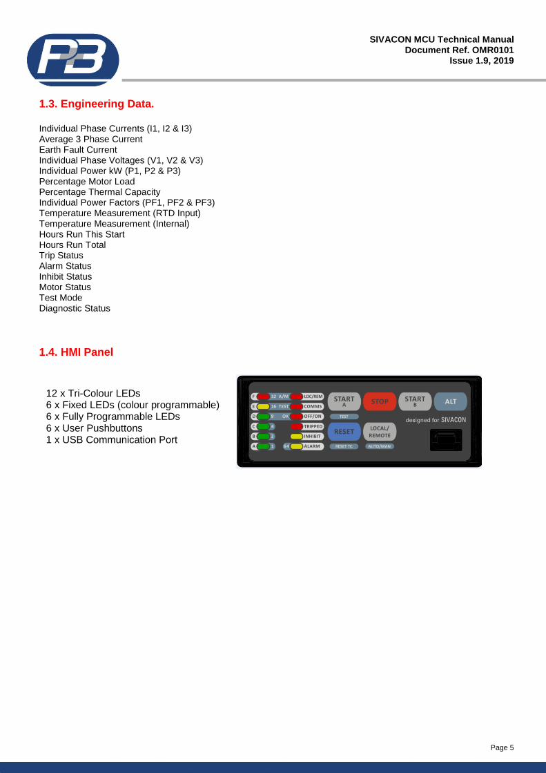
1.4. HMI Panel
12 x Tri-Colour LEDs 6 x Fixed LEDs (colour programmable) 6 x Fully Programmable LEDs 6 x User Pushbuttons 1 x USB Communication Port
Page 6
SIVACON MCU Technical Manual Document Ref. OMR0101
Issue 1.9, 2019
1.5. Starting Logic.
Direct-on-Line Star/Delta 2 Star/Delta 3 (includes line contactor) Direct-on-Line Reversing 2 Speed (separate winding and tapped winding motors) ACB (mechanically latched contactor) Direct-on-Line Heater (with a facility to inject winding heating supply) Direct-on-Line Reversing with Heater (with a facility to inject winding heating supply) Variable Speed Drive No Starter (protection only mode)
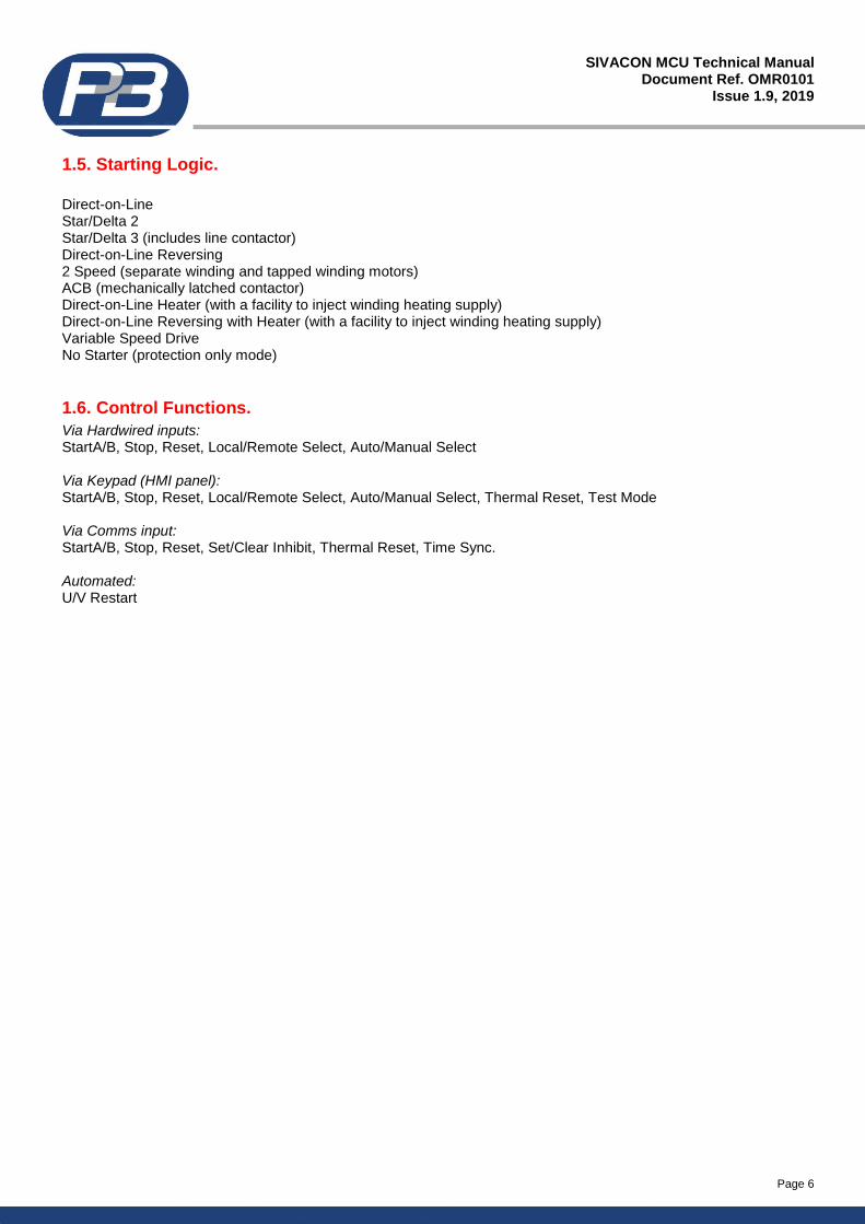
1.6. Control Functions.
Via Hardwired inputs: StartA/B, Stop, Reset, Local/Remote Select, Auto/Manual Select Via Keypad (HMI panel): StartA/B, Stop, Reset, Local/Remote Select, Auto/Manual Select, Thermal Reset, Test Mode Via Comms input: StartA/B, Stop, Reset, Set/Clear Inhibit, Thermal Reset, Time Sync. Automated: U/V Restart
Page 7
SIVACON MCU Technical Manual Document Ref. OMR0101
Issue 1.9, 2019
1.7. Control Output Relays.
Output Relay #1, Output Relay #2, Output Relay #3. Some of the Output Relays are pre-set depending on the Starter Type chosen. As shown below.
Others can be programmed by the user. They can be programmed as follows: - Not Used, Follow A, Follow B, Invert A, Invert B, Trip, Trip FS, Alarm, Alarm FS, Healthy, Healthy FS, Warning, Serial-Possible, Panel-Possible, Remote-Possible, U/V Restart, Internal Error, Auxiliary Trip, Indicator 1-5, Indicator FS 1-5, Inhibit, and Inhibit FS FS = Failsafe (normally energised)
1.8. Control Inputs.
The user can define the function of the five optically isolated inputs from the list of 17 below. 1. Not Used 9. Reset Faults 17. External Fault 5 2. Start A 10. Test Mode 3. Start B 11. Speed Switch 4. Stop 12. Restart 5. Contactor A 13. External Fault 1 6. Contactor B 14. External Fault 2 7. Auto / Manual 15. External Fault 3 8. Local / Remote 16. External Fault 4
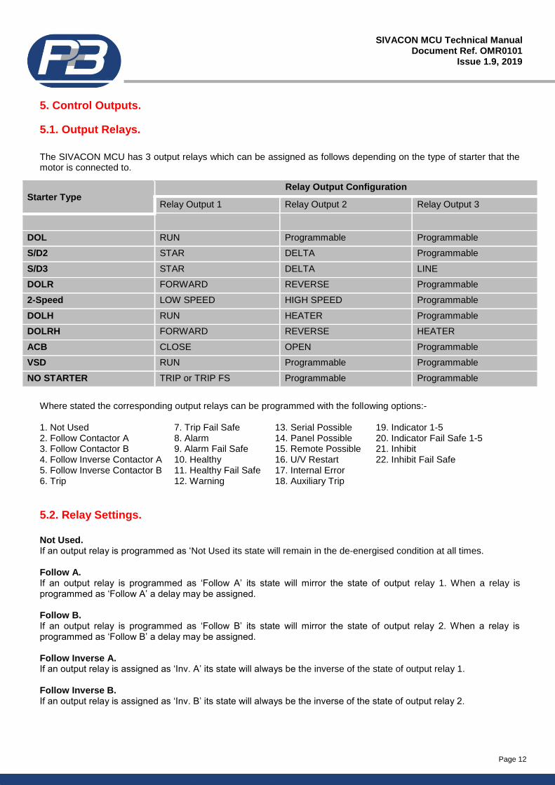
Starter Type Relay Output Configuration
Relay Output 1 Relay Output 2 Relay Output 3
DOL RUN Programmable Programmable
S/D2 STAR DELTA Programmable
S/D3 STAR DELTA LINE
DOLR FORWARD REVERSE Programmable
2-Speed LOW SPEED HIGH SPEED Programmable
DOLH RUN HEATER Programmable
DOLRH FORWARD REVERSE HEATER
ACB CLOSE OPEN Programmable
VSD RUN Programmable Programmable
NO STARTER TRIP or TRIP FS Programmable Programmable
Page 8
SIVACON MCU Technical Manual Document Ref. OMR0101
Issue 1.9, 2019
2. Technical Specification.
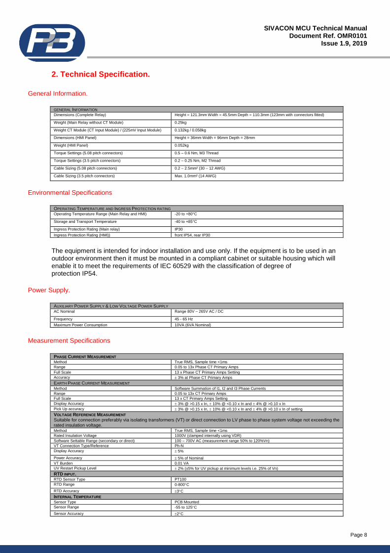
General Information.
GENERAL INFORMATION Dimensions (Complete Relay) Height = 121.3mm Width = 45.5mm Depth = 110.3mm (123mm with connectors fitted)
Weight (Main Relay without CT Module) 0.25kg
Weight CT Module (CT Input Module) / (225mV Input Module) 0.132kg / 0.058kg
Dimensions (HMI Panel) Height = 36mm Width = 96mm Depth = 28mm
Weight (HMI Panel) 0.052kg
Torque Settings (5.08 pitch connectors) 0.5 – 0.6 Nm, M3 Thread
Torque Settings (3.5 pitch connectors) 0.2 – 0.25 Nm, M2 Thread
Cable Sizing (5.08 pitch connectors) 0.2 – 2.5mm² (30 – 12 AWG)
Cable Sizing (3.5 pitch connectors) Max. 1.0mm² (14 AWG)
Environmental Specifications
OPERATING TEMPERATURE AND INGRESS PROTECTION RATING Operating Temperature Range (Main Relay and HMI) -20 to +80°C
Storage and Transport Temperature -40 to +85°C
Ingress Protection Rating (Main relay) IP30
Ingress Protection Rating (HMI)) front IP54, rear IP30
The equipment is intended for indoor installation and use only. If the equipment is to be used in an outdoor environment then it must be mounted in a compliant cabinet or suitable housing which will enable it to meet the requirements of IEC 60529 with the classification of degree of protection IP54.
Power Supply.
AUXILIARY POWER SUPPLY & LOW VOLTAGE POWER SUPPLY AC Nominal Range 80V – 265V AC / DC
Frequency 45 - 65 Hz
Maximum Power Consumption 10VA (6VA Nominal)
Measurement Specifications
PHASE CURRENT MEASUREMENT Method True RMS, Sample time <1ms
Range 0.05 to 13x Phase CT Primary Amps
Full Scale 13 x Phase CT Primary Amps Setting
Accuracy 3% at Phase CT Primary Amps
EARTH PHASE CURRENT MEASUREMENT Method Software Summation of I1, I2 and I3 Phase Currents
Range 0.05 to 13x CT Primary Amps
Full Scale 13 x CT Primary Amps Setting
Display Accuracy 3% @ >0.15 x In, 10% @ <0.10 x In and 4% @ >0.10 x In
Pick Up accuracy 3% @ >0.15 x In, 10% @ <0.10 x In and 4% @ >0.10 x In of setting
VOLTAGE REFERENCE MEASUREMENT Suitable for connection preferably via isolating transformers (VT) or direct connection to LV phase to phase system voltage not exceeding the rated insulation voltage. Method True RMS, Sample time <1ms
Rated Insulation Voltage 1000V (clamped internally using VDR)
Software Settable Range (secondary or direct) 100 – 700V AC (measurement range 50% to 120%Vn)
VT Connection Type/Reference Ph-N
Display Accuracy 5%
Power Accuracy 5% of Nominal
VT Burden 0.01 VA
UV Restart Pickup Level 2% (±5% for UV pickup at minimum levels i.e. 25% of Vn)
RTD INPUT. RTD Sensor Type PT100
RTD Range 0-800C
RTD Accuracy 3C
INTERNAL TEMPERATURE Sensor Type PCB Mounted
Sensor Range -55 to 125C
Sensor Accuracy 2C
Page 9
SIVACON MCU Technical Manual Document Ref. OMR0101
Issue 1.9, 2019
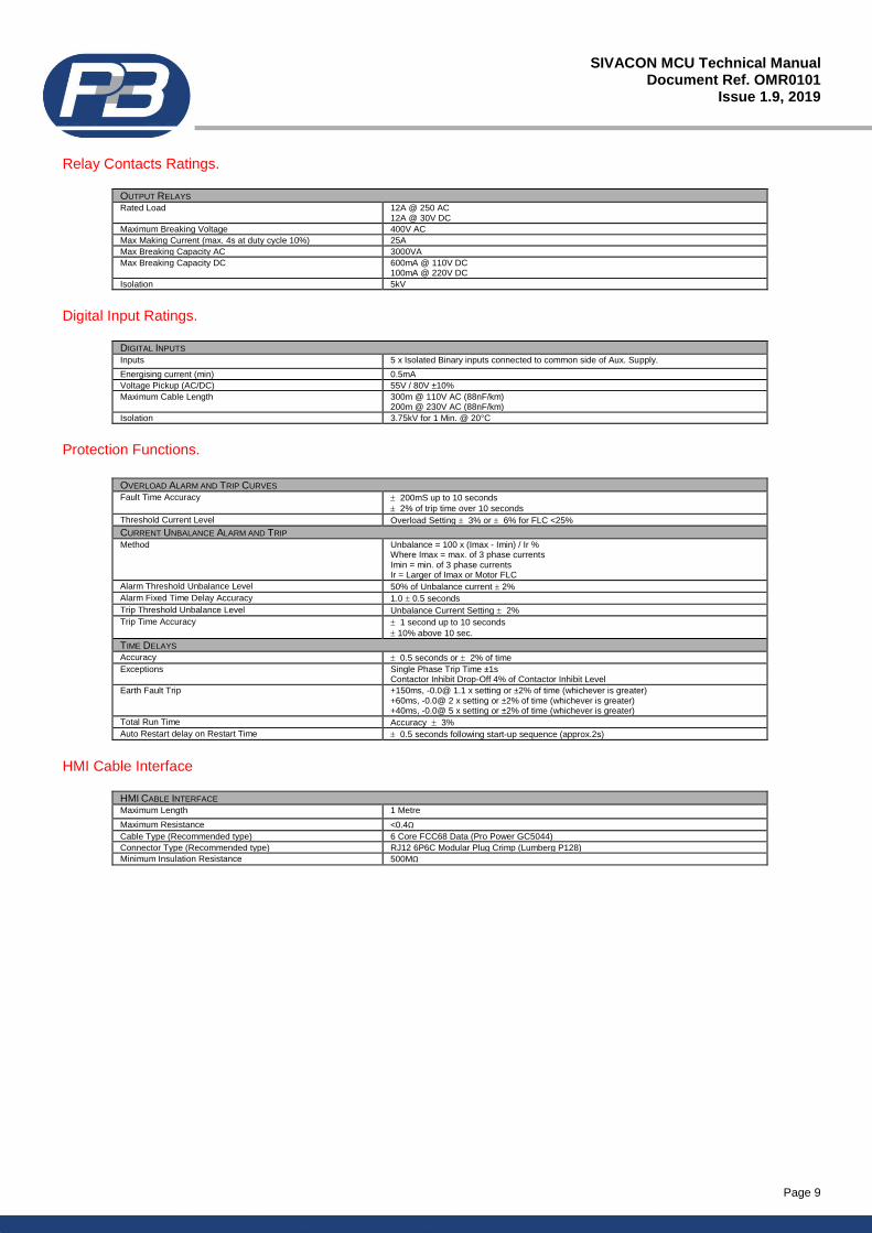
Relay Contacts Ratings.
OUTPUT RELAYS Rated Load 12A @ 250 AC
12A @ 30V DC
Maximum Breaking Voltage 400V AC
Max Making Current (max. 4s at duty cycle 10%) 25A
Max Breaking Capacity AC 3000VA
Max Breaking Capacity DC 600mA @ 110V DC 100mA @ 220V DC
Isolation 5kV
Digital Input Ratings.
DIGITAL INPUTS Inputs 5 x Isolated Binary inputs connected to common side of Aux. Supply.
Energising current (min) 0.5mA
Voltage Pickup (AC/DC) 55V / 80V ±10%
Maximum Cable Length 300m @ 110V AC (88nF/km) 200m @ 230V AC (88nF/km)
Isolation 3.75kV for 1 Min. @ 20°C
Protection Functions.
OVERLOAD ALARM AND TRIP CURVES Fault Time Accuracy 200mS up to 10 seconds
2% of trip time over 10 seconds
Threshold Current Level Overload Setting 3% or 6% for FLC <25%
CURRENT UNBALANCE ALARM AND TRIP Method Unbalance = 100 x (Imax - Imin) / Ir %
Where Imax = max. of 3 phase currents Imin = min. of 3 phase currents Ir = Larger of Imax or Motor FLC
Alarm Threshold Unbalance Level 50% of Unbalance current 2%
Alarm Fixed Time Delay Accuracy 1.0 0.5 seconds
Trip Threshold Unbalance Level Unbalance Current Setting 2%
Trip Time Accuracy 1 second up to 10 seconds
10% above 10 sec.
TIME DELAYS Accuracy 0.5 seconds or 2% of time
Exceptions Single Phase Trip Time ±1s Contactor Inhibit Drop-Off 4% of Contactor Inhibit Level
Earth Fault Trip +150ms, -0.0@ 1.1 x setting or ±2% of time (whichever is greater) +60ms, -0.0@ 2 x setting or ±2% of time (whichever is greater) +40ms, -0.0@ 5 x setting or ±2% of time (whichever is greater)
Total Run Time Accuracy 3%
Auto Restart delay on Restart Time 0.5 seconds following start-up sequence (approx.2s)
HMI Cable Interface
HMI CABLE INTERFACE Maximum Length 1 Metre
Maximum Resistance <0.4Ω
Cable Type (Recommended type) 6 Core FCC68 Data (Pro Power GC5044)
Connector Type (Recommended type) RJ12 6P6C Modular Plug Crimp (Lumberg P128)
Minimum Insulation Resistance 500MΩ
Page 10
SIVACON MCU Technical Manual Document Ref. OMR0101
Issue 1.9, 2019
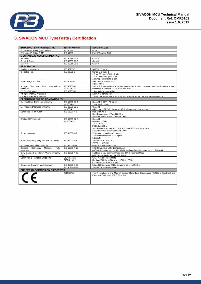
3. SIVACON MCU TypeTests / Certification
IP RATING / ENVIRONMENTAL TEST STANDARD SEVERITY LEVEL Enclosure IP Rating (Main Relay) IEC 60529 IP30
Enclosure IP Rating (HMI) IEC 60529 front IP54, rear IP30
MECHANICAL / ENVIRONMENTAL Vibration IEC 60255-21-1 Class I
Shock & Bump IEC 60255-21-2 Class I
Seismic IEC 60255-21-3 Class I
ELECTRICAL Insulation resistance IEC 60255-5 500 Vdc, 5 secs
Dielectric Test IEC 60255-5 Series C of table 1 2.5 kV CT Inputs 50Hz, 1 min 1.0 kV all other inputs. 1 min 1.5Kv open contacts, 1 min
High Voltage Impulse IEC 60255-5 5 kV peak 1.2/50uS,0.5J 3 pos, 3 neg
Voltage Dips and Short Interruptions immunity
IEC 60255-11 (61000-4-11)
3 dips & 3 interruptions at 10 sec intervals of duration between 10mS and 500mS at zero crossings. Variations 100%, 60% and 30%
DC Ripple Immunity IEC 60255-11 15% ripple of rated value
VT input Thermal Withstand 120% Vn, continuous
CT input Thermal Withstand 250xIn half wave,100xIn for 1 second 30xIn for 10 second and 4xIn continuous
ELECTROMAGNETIC COMPATIBILITY Electrical Fast Transients Immunity IEC 60255-22-4
(61000-4-4) Class III, 2.0 kV – All inputs 1 min each polarity
Electrostatic Discharge Immunity IEC 60255-22-2 (61000-4-2)
Class III 6 kV contact 8kV air discharge, 10 discharges at 1 sec intervals
Conducted RF Immunity IEC 61000-4-6 0.15 to 80 MHz Spot Frequencies: 27 and 68 MHz Severity 10V/m 80% modulated 1 kHz
Radiated RF Immunity IEC 60255-22-3 (61000-4-3)
Class III 80MHz to 1GHz 1.4 to 2GHz 2GHz to 2.7GHz Spot Frequencies: 80, 160, 380, 450, 900, 1850 and 2150 MHz Severity 10V/m 80% modulated 1 kHz
Surge Immunity IEC 61000-4-5 2kV common mode – All Inputs 1kV differential mode – All Inputs 1.2/50uS
Power Frequency Magnetic Field Immunity IEC 61000-4-8 300A/m for 3 seconds 30A/m for 1 minute
Pulse Magnetic Field Immunity IEC 61000-4-9 8/20uS, 300/1000A/m ±Ve
Damped Oscillatory Magnetic Field Immunity
IEC 61000-4-10 100KHz and 1.0 MHz, 100/1000A/m 40 Transients per second @ 100KHz and 400 Transients per second @1.0MHz
Slow Damped Oscillatory Wave Immunity (1MHz)
IEC 61000-4-18 1MHz @ 2.5kV Common Mode and 1kV Differential Mode 400 Transients per second @1.0MHz
Conducted & Radiated Emissions CISPR 16-2-3 CISPR 16-2-1
Class A interference limits Radiated 30Mhz to 1GHz and 1GHz to 2GHz Conducted 150KHz to 30MHz
Conducted Common Mode immunity IEC 61000-4-16 IEC 60255-22-7
50 and 60Hz sweep @10s durations 15Hz to 150KHz 100V/300V at 50 and 60Hz
EUROPEAN COMMISSION DIRECTIVES
2011/65/EU The Restriction of the Use of Certain Hazardous Substances (RoHS) in Electrical and Electronic Equipment (EEE) Directive
Page 11
SIVACON MCU Technical Manual Document Ref. OMR0101
Issue 1.9, 2019
4. Analogue Inputs.
4.1. Power Supply Live.
The SIVACON MCU requires an AC or DC Voltage to supply the unit, the same supply is used as a reference for the digital inputs, it is not possible to power the auxiliary supply of the relay from a different supply to the control inputs. The SIVACON MCU can alternatively be supplied with a Low Voltage Power Supply (PSU) and Low Voltage digital inputs. (24/48Vac/dc) – this must be requested at the point of order. The SIVACON MCU monitors the power supply assumed to be derived from the primary side of the contactor within the starter cubicle or from the MCC busbars to provide an Undervoltage Restart facility. When enabled in the Starter Settings page the SIVACON MCU monitors the supply and in the event of a failure will maintain the start signal to the motor for up to 200 milli-seconds. Beyond 200ms the unit will trip the motor and should the power supply be restored within the programmable Restart Time (0.2 to 200s) the unit will restart the motor after a programmable time delay (1-120s). Should the voltage not be restored within the programmable Restart Time the motor will not be automatically restarted. There is also a digital input that can be used to enable or block the Undervoltage Restart. If the input is closed then a restart can occur, if open, then the restart is blocked. If no digital input is set to Restart then a restart will always occur in line with the required conditions.
4.2. Voltage Reference Inputs.
The SIVACON MCU monitors 3 phase voltage, which can be directly connected for voltages up to 690V. In order that the SIVACON MCU can measure and display the actual voltage two software controlled options are available to configure the VT ratio, these programmable settings are shown as VT Primary and VT Secondary. With the use of external Voltage Transformer (VT or PT) the SIVACON MCU can monitor voltages up to 22kV. The voltage reference inputs on the SIVACON MCU are self-protected through the use of high impedance fusible resistors and voltage dependent resistors. There is no requirement to fit additional fusing to these inputs.
4.3. Current Sensor Inputs.
The current inputs to the SIVACON MCU are housed internally and use a ‘pass through’ cable design, which can help achieve the small size and form part of the integral starter cubicle. The SIVACON MCU has two CT options, one module for motor full load currents up to 10A and a second CT module for motor full load currents up to 29A. For full load currents greater than 29A traditional iron core protection interposing CT’s can be used (i.e. 100:5 5p10) To allow MCC manufacturers to use the smallest size compartments a low power CT interface module is available within the SIVACON MCU device, this can be used in place of traditional iron core CT’s where space is limited. Earth fault measurement is achieved through an internal residual summation of the 3 phase currents.
4.4. Temperature Input(s).
The SIVACON MCU is fitted with a single channel RTD temperature input Resistance Temperature Detectors (RTDs) can be connected to this input, if the resistance type of RTD is selected. For RTD devices all readings and protection
settings are shown in terms of degrees C. The alarm and tripping range for RTD sensors can be adjusted between 0
and 250C.
Page 12
SIVACON MCU Technical Manual Document Ref. OMR0101
Issue 1.9, 2019
5. Control Outputs.
5.1. Output Relays.
The SIVACON MCU has 3 output relays which can be assigned as follows depending on the type of starter that the motor is connected to.
Where stated the corresponding output relays can be programmed with the following options:- 1. Not Used 7. Trip Fail Safe 13. Serial Possible 19. Indicator 1-5 2. Follow Contactor A 8. Alarm 14. Panel Possible 20. Indicator Fail Safe 1-5 3. Follow Contactor B 9. Alarm Fail Safe 15. Remote Possible 21. Inhibit 4. Follow Inverse Contactor A 10. Healthy 16. U/V Restart 22. Inhibit Fail Safe 5. Follow Inverse Contactor B 11. Healthy Fail Safe 17. Internal Error 6. Trip 12. Warning 18. Auxiliary Trip
5.2. Relay Settings.
Not Used. If an output relay is programmed as ‘Not Used its state will remain in the de-energised condition at all times. Follow A. If an output relay is programmed as ‘Follow A’ its state will mirror the state of output relay 1. When a relay is programmed as ‘Follow A’ a delay may be assigned. Follow B. If an output relay is programmed as ‘Follow B’ its state will mirror the state of output relay 2. When a relay is programmed as ‘Follow B’ a delay may be assigned. Follow Inverse A. If an output relay is assigned as ‘Inv. A’ its state will always be the inverse of the state of output relay 1. Follow Inverse B. If an output relay is assigned as ‘Inv. B’ its state will always be the inverse of the state of output relay 2.
Starter Type Relay Output Configuration
Relay Output 1 Relay Output 2 Relay Output 3
DOL RUN Programmable Programmable
S/D2 STAR DELTA Programmable
S/D3 STAR DELTA LINE
DOLR FORWARD REVERSE Programmable
2-Speed LOW SPEED HIGH SPEED Programmable
DOLH RUN HEATER Programmable
DOLRH FORWARD REVERSE HEATER
ACB CLOSE OPEN Programmable
VSD RUN Programmable Programmable
NO STARTER TRIP or TRIP FS Programmable Programmable
Page 13
SIVACON MCU Technical Manual Document Ref. OMR0101
Issue 1.9, 2019
Trip. If an output relay is assigned as ‘Trip’ then this relay will change state from the de-energised to the energised relay contact when triggered by any protection function or external device connected to the relay that is configured to trip the motor.
Trip Fail Safe. If an output relay is assigned as ‘Trip FS’ (Trip Failsafe) then this relay will change state from energised to the de-energised relay contact when triggered by any protection function or external device connected to the relay that is configured to trip the motor. Alarm. If an output relay is assigned as ‘Alarm’ then this relay will change state from de-energised to the energised relay contact when triggered by any protection function or external device connected to the relay that is configured to alarm. Alarm Fail Safe. If an output relay is assigned as ‘Alarm FS’ then this relay will change state from energised to the de-energised relay contact when triggered by any protection function or external device connected to the relay that is configured to alarm. Healthy. If an output relay is assigned as “Healthy” this relay will be in its de-energised state at all times while the unit reports the motor as being healthy. This relay will be energised when the unit registers either an Alarm or Fault condition or the motor has been inhibited from starting. Healthy Fail Safe. If an output relay is assigned as ‘Healthy FS’ (Healthy Failsafe) this relay will be in its energised state at all times while the unit reports the motor as being healthy. This relay will be de-energised when the unit registers either an Alarm or Fault condition or the motor has been inhibited from starting. Warning. If an output relay is assigned as ‘Warning’ then it will change state when any enabled protection function has exceeded its pickup value. The relay is not latching. When the pickup setting is no longer violated the output relay assigned as ‘Warning’ will be de-energised. The ‘Warning’ relay does not wait until the expiry of a trip or alarm timer before being energised. It will energise immediately after an enabled protection feature has its pickup point violated or a digital input registers a fault status. Serial Possible. If an output relay is assigned as ‘Serial Pos’ this relay will be energised only when the motor is available to be started through the serial port, via a serial command. For details on configuring possible start sources see section13 Panel Possible If an output relay is assigned as ‘Panel Pos’ this relay will be energised only when the motor is available to be started from the front panel of the relay. For details on configuring possible start sources see section13 Remote Possible. If an output relay is assigned as ‘Remote Pos’ this relay will be energised only when the motor is available to be started from a remote station via a digital input. For details on configuring possible start sources see section13 U/V Restart If an output relay is assigned as “U/V Restart” when in No Starter mode this relay will energise when a U/V restart is in progress thereby allowing the motor to be started again. Once the unit goes into starting mode the U/V Restart relay will de-energise (see section 13 for more information on undervoltage restart) Internal Error If an output relay is assigned as “Internal. Error” this relay will energise when an Internal Error within the SIVACON MCU has been detected, either by the internal diagnostics or the watchdog facility. The Internal Error protection requires to be enabled for this output relay to function upon detection of an internal fault/error.
Page 14
SIVACON MCU Technical Manual Document Ref. OMR0101
Issue 1.9, 2019
Auxiliary Trip If an output relay is assigned as ‘Aux Trip’’ this relay will be energised when the phase currents are above the set value of Cont Inhibit setting (6 – 12 x FLC). This can allow an upstream breaker to open, one which is capable of breaking the entire available fault current. see section 15.1.14. Short Circuit. Indicator 1-5. If an output relay is assigned as any of the 5 available Indicators then this relay will change state from de-energised to the energised relay contact when triggered by any protection function or external device connected to the relay that is configured to indicate on that same indicator channel. An Indicator relay will only be energised following the expiry of the delay timer (if a delay is assigned) for a protection function or external device that registers its pickup setting or fault status has been violated. When the pickup setting or fault status is no longer violated the output relay assigned to the relevant Indicator will be de-energised. An Indicator is not latched. Typically these are used for single function signalling or used as output indicators to other drives when forming part of a hardwired permissive control system. Indicator 1-5 Fail Safe If an output relay is assigned as any of the 5 available Indicators then this relay will change state from energised to the de-energised relay contact when triggered by any protection function or external device connected to the relay that is configured to indicate on that same indicator channel. Inhibit If an output relay is assigned as ‘Inhibit’ then this relay will change state from de-energised to the energised relay contact when triggered by any protection function or external device connected to the relay that is configured to Inhibit. Inhibit Fail Safe. If an output relay is assigned as ‘Inhibit FS’ then this relay will change state from energised to the de-energised relay contact when triggered by any protection function or external device connected to the relay that is configured to Inhibit.
Page 15
SIVACON MCU Technical Manual Document Ref. OMR0101
Issue 1.9, 2019
6. Control Inputs.
The SIVACON MCU offers 5 digital inputs to provide full control and indication for the motor starter. The supply to these terminals is derived from the same supply as the auxiliary supply to the relay. The digital inputs are galvanically isolated. The 5 digital inputs are software selectable by the user from the list described in the following sections, please note that only 1 input function can be used per digital input, multiple instances of the same function are not allowed. Not Used If an input is set to ‘Not Used’ then regardless of the input’s actual status (i.e. energised or de-energised), no action will be taken or controlled using this input. The actual ON/OFF status of the input will however still be indicated via the communication interface. Start A and Start B Inputs. When one of these inputs are closed the corresponding output relay is energised as long as the Start Setup Sources has been set accordingly (see section 5.1 and section 13), and provided all other External Faults are in the healthy state. Start A only is used for DOL, DOL Forward, Star or Low Speed contactors whilst Start B is used for DOL Reverse or High Speed. The starter settings menu allows these Start inputs to be either momentary, i.e. from push buttons or maintained, i.e. from PLC outputs not both. Stop Input. If this input is open circuited the motor will be switched off and inhibited from starting as long as the Stop Setup Sources have been set to allow the stop to be active from the remote source. Contactor A and B Status. These status inputs from the contactors allow the SIVACON MCU to determine the status of both the A and B contactors, also known as Relays 1 and 2. Cont A is the feedback signal for a Start A command and Cont B is the feedback signal for a Start B command. Monitoring of these contacts also provides protection against 'Control Open' (when a SIVACON MCU START command is not confirmed by these inputs, Cont A and/or Cont B) and 'Welded Contact' (when SIVACON MCU STOP command is not confirmed by these inputs). Only when the Contactor Fault protection is enabled do these ‘active faults’ appear under warranted situations. Test Mode. When in the Test mode the SIVACON MCU will disable Undercurrent Protection, Undervoltage, Single Phase and Phase Sequence protection functions, as well as the External Faults if set to Disable in Test. This allows full functional testing to be performed without the need for voltage or current injection and will allow secondary injection testing to be carried out on all protective functions except for those disabled by the feature. Reset Fault. This input enables the operator to reset a SIVACON MCU Fault or Alarm condition. The Input can only perform a reset if the following conditions are met: 1. The Protection Settings for the specific fault or alarm are set to allow remote resets. 2. The condition that caused the Fault or Alarm to occur no longer exists. Providing conditions 1 and 2 are met an operator can override the settings in the Protection Settings by closing the Authorise digital input and pressing the Reset digital input. Auto/Manual and Local/Remote Inputs. These inputs are used to determine the source of both the Start Signal and Stop Signal to the motor. They are configured in the Start Setup Source and the Stop Setup Source. (see section 13) Speed Switch. Closing of this input reduces the trip time on the cold and hot curves by 50%. A tachometer is generally used on the rotor to determine if the shaft is turning the transducer is fed to this input. This provides a faster trip for stalled motors.
Page 16
SIVACON MCU Technical Manual Document Ref. OMR0101
Issue 1.9, 2019
External Faults 1-5. The flexibility of the External Fault inputs gives SIVACON MCU an intelligent PLC aspect to protective relaying. External Faults are voltage based and are assigned to digital inputs to perform a wide variety of roles. Multiple plant interlocking, process shutdown or for use as a gateway onto the serial network for digital signals via the SIVACON MCU. External Faults can be configured as independent protective functions and can be configured to any combination of; Trip, Alarm, Inhibit or just to Stop the drive. The normal reset types are available; Auto, Panel, Serial and Remote. The fault status of the input is programmable such that OFF = Fault or ON = Fault where the input is fed from either a normally closed (NC) or normally open (NO) source. The trip time (or time to take the configured action) is settable in the range 0.1 to 60 seconds. Restart. This input will inhibit or permit an Undervoltage Restart to take place. This is to allow the differentiation between power losses that would and would not allow an automated restart of the drive. If the input is closed a restart can occur and if the input is open then the restart will be blocked. If no digital input is set to Restart then an Undervoltage Restart would always occur, if enabled.
Page 17
SIVACON MCU Technical Manual Document Ref. OMR0101
Issue 1.9, 2019
7. Serial Ports.
7.1. RS485
The Serial Port supplied with SIVACON MCU as standard utilises a half-duplex RS485 protocol allowing up to 32 units to be daisy-chained together, or to be multi-drop connected with a single shielded twisted pair cable. The SIVACON MCU in addition to its very comprehensive protection and control features has been equipped with a very powerful data communications system. This extends its boundaries far beyond a motor protection controller into the realms of a complete motor management system. It provides high-speed data acquisition to supervisory computers to form a complete motor management system. Each SIVACON MCU can be connected to an isolated data highway using RS485 communications. Up to 32 units can be connected to each data highway. The host system can interrogate the unit to monitor motor status, running conditions, historical data and fault data as well as control functions such as a start and stop to the motor and reset fault / alarm conditions. The SIVACON MCU is available with P&B network gold (P&B protocol) installed for use with the Xcell Data Concentrator for fully Integrated Protection, Control & Monitoring Systems with full dual redundancy or with a Slave implementation of Modbus RTU protocol for small systems and direct Modbus access to devices where data concentration is not required. (see section 10 for more details)
7.2. Dual RS485
The SIVACON MCU can be supplied with an additional RS485 module (this must be specified at the time of ordering). The dual RS485 provides a second fully isolated RS485 connection, which can support a half-duplex RS485 protocol allowing up to 32 units to be daisy-chained together, or to be multi-drop connected with a single shielded twisted pair cable. The Dual RS485 SIVACON MCU relay provides dual redundant communication, each RS485 port can be individually programmed to support P&B network gold (P&B protocol) installed for use with the Xcell Data Concentrator for fully Integrated Protection, Control & Monitoring Systems or with a Slave implementation of Modbus RTU protocol.
7.3. RS232/HMI Interface
The unit is additionally fitted with a front mounted RS232 port. This port is primarily used to connect the SIVACON MCU to the HMI operator panel. However, for installations, which do not use or require the HMI operator panel, this port can be used as a standard RS232 port to allow relay interface using the P&B Protocol. The protocol setting for this port is fixed to operate on P&B protocol only, this is independent of the rear RS485 port(s) configuration. Full details of the protocols, device mapping and other support documents are available on request or via the PBSIGROUP website. Information on the Xcell Data Concentrator is contained in the P&B Integrated Protection & Control System Integrators Manual, available on request or via the PBSIGROUP website.
Page 18
SIVACON MCU Technical Manual Document Ref. OMR0101
Issue 1.9, 2019
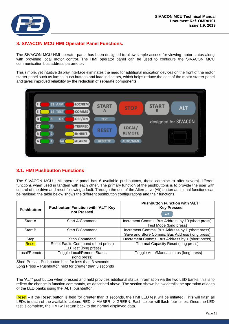
8. SIVACON MCU HMI Operator Panel Functions.
The SIVACON MCU HMI operator panel has been designed to allow simple access for viewing motor status along with providing local motor control. The HMI operator panel can be used to configure the SIVACON MCU communication bus address parameter. This simple, yet intuitive display interface eliminates the need for additional indication devices on the front of the motor starter panel such as lamps, push buttons and load indicators, which helps reduce the cost of the motor starter panel and gives improved reliability by the reduction of separate components.
8.1. HMI Pushbutton Functions
The SIVACON MCU HMI operator panel has 6 available pushbuttons, these combine to offer several different functions when used in tandem with each other. The primary function of the pushbuttons is to provide the user with control of the drive and reset following a fault. Through the use of the Alternative [Alt] button additional functions can be realised; the table below shows the different pushbutton configurations and their functions.
Pushbutton Pushbutton Function with ‘ALT’ Key
not Pressed
Pushbutton Function with ‘ALT’ Key Pressed
Start A Start A Command Increment Comms. Bus Address by 10 (short press)
Test Mode (long press)
Start B Start B Command Increment Comms. Bus Address by 1 (short press) Save and Store Comms. Bus Address (long press)
Stop Stop Command Decrement Comms. Bus Address by 1 (short press)
Reset Reset Faults Command (short press) LED Test (long press)
Thermal Capacity Reset (long press)
Local/Remote Toggle Local/Remote Status (long press)
Toggle Auto/Manual status (long press)
Short Press – Pushbutton held for less than 3 seconds Long Press – Pushbutton held for greater than 3 seconds The ‘ALT’ pushbutton when pressed and held provides additional status information via the two LED banks, this is to reflect the change in function commands, as described above. The section shown below details the operation of each of the LED banks using the ‘ALT’ pushbutton. Reset – if the Reset button is held for greater than 3 seconds, the HMI LED test will be initiated. This will flash all LEDs in each of the available colours RED -> AMBER -> GREEN. Each colour will flash four times. Once the LED test is complete, the HMI will return back to the normal displayed data.
Page 19
SIVACON MCU Technical Manual Document Ref. OMR0101
Issue 1.9, 2019
1 + 2 + 8 + 16 = 27
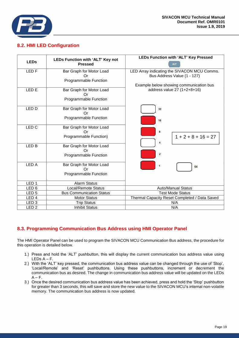
8.2. HMI LED Configuration
LEDs LEDs Function with ‘ALT’ Key not
Pressed
LEDs Function with ‘ALT’ Key Pressed
LED F Bar Graph for Motor Load
Or Programmable Function
LED Array indicating the SIVACON MCU Comms. Bus Address Value (1 - 127)
Example below showing communication bus
address value 27 (1+2+8+16)
LED E Bar Graph for Motor Load Or
Programmable Function
LED D Bar Graph for Motor Load Or
Programmable Function
LED C Bar Graph for Motor Load Or
Programmable Function)
LED B Bar Graph for Motor Load Or
Programmable Function
LED A Bar Graph for Motor Load Or
Programmable Function
LED 1 Alarm Status
LED 6 Local/Remote Status Auto/Manual Status
LED 5 Bus Communication Status Test Mode Status
LED 4 Motor Status Thermal Capacity Reset Completed / Data Saved
LED 3 Trip Status N/A
LED 2 Inhibit Status N/A
8.3. Programming Communication Bus Address using HMI Operator Panel
The HMI Operator Panel can be used to program the SIVACON MCU Communication Bus address, the procedure for this operation is detailed below.
1.) Press and hold the ‘ALT’ pushbutton, this will display the current communication bus address value using LEDs A – F.
2.) With the ‘ALT’ key pressed, the communication bus address value can be changed through the use of ‘Stop’, ‘Local/Remote’ and ‘Reset’ pushbuttons. Using these pushbuttons, increment or decrement the communication bus as desired. The change in communication bus address value will be updated on the LEDs A – F.
3.) Once the desired communication bus address value has been achieved, press and hold the ‘Stop’ pushbutton for greater than 3 seconds, this will save and store the new value to the SIVACON MCU’s internal non-volatile memory. The communication bus address is now updated.
Page 20
SIVACON MCU Technical Manual Document Ref. OMR0101
Issue 1.9, 2019
9. Setting Sheets
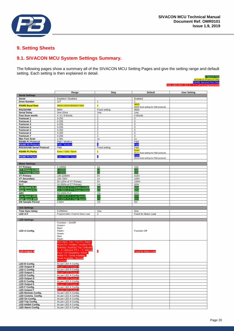
9.1. SIVACON MCU System Settings Summary.
The following pages show a summary all of the SIVACON MCU Setting Pages and give the setting range and default setting. Each setting is then explained in detail.
2-Speed Only MODBUS Protocol Only
RS485 Second Port Only Only valid when LED A – F is set to programmable
Range Step Default User Setting
Serial Settings
Serial Enabled / Disabled Enabled
Drive Number 127 1 1
RS485 Baud Rate 9600/19200/38400/57600 1 9600 (9600 fixed setting for P&B protocol)
RS232/HMI 9600 Fixed setting 9600
Serial Delay 0ms-20ms 1ms 1ms
Fast Scan words 4 / 6 / 8 Words 1 4 Words
Fastscan 1 0-255 2 0
Fastscan 2 0-255 2 0
Fastscan 3 0-255 2 0
Fastscan 4 0-255 2 0
Fastscan 5 0-255 2 0
Fastscan 6 0-255 2 0
Fastscan 7 0-255 2 0
Max Fast Scan 1-30s 1s 1s
RS485 P1 Protocol P&B / Modbus 1 P&B
RS485 P2 Protocol P&B / Modbus 1 P&B
RS232/USB Serial Protocol P&B Fixed setting P&B
RS485 P1 Parity Even / Odd / None 1 Even (Even fixed setting for P&B protocol)
RS485 P2 Parity Even / Odd / None 1 Even (Even fixed setting for P&B protocol)
Motor Settings
CT Primary 5-1000A 1A 10A
CT Primary (LOW) 5-1000A 1A 10A
CT Primary (HIGH) 5-1000A 1A 10A
VT Primary 100-22000V 5V 415V
VT Secondary 100-700V 1V 100V
Voltage 50-125% of VT Primary 5V 100%
FLC 10-200% of CT Primary 1% 50%
Low Speed FLC 10-200% of CT Primary (LOW) 1% 50%
High Speed FLC 10-200% of CT Primary (HIGH) 1% 50%
ARC 50-100% FLC 1% 50%
Low Speed ARC 50-100% FLC (Low Speed) 1% 50%
High Speed ARC 50-100% FLC (High Speed) 1% 50%
kW Sample Period 5-60m 1m 5m
Unit Settings
Time Sync Delay 0-2000ms 1ms 0ms
LED A-F Programmable / Fixed for Motor Load 1 Fixed for Motor Load
LED Settings
LED A Config.
Function – On/Off Green+ Red+ Flash+ Green- Red- Flash-
Function Off
LED Output A
Not Used / Trip / Trip FS / Alarm / Alarm FS / Healthy / Healthy FS / Warning / Auxiliary Trip / Indicator 1 – 5 / Indicator FS 1 – 5 / Internal Error / UV Restarting / Inhibit / Inhibit FS / Serial Available / Panel Available / Remote Available
1 Fixed for Motor Load
LED B Config. As per LED A Config.
LED Output B As per LED Output A
LED C Config. As per LED A Config.
LED Output C As per LED Output A
LED D Config. As per LED A Config.
LED Output D As per LED Output A
LED E Config. As per LED A Config.
LED Output E As per LED Output A
LED F Config. As per LED A Config.
LED Output F As per LED Output A
LED Remote Config. As per LED A Config.
LED Comms. Config. As per LED A Config.
LED On Config. As per LED A Config.
LED Trip Config. As per LED A Config.
LED Inhibit Config. As per LED A Config.
LED Alarm Config. As per LED A Config.
Page 21
SIVACON MCU Technical Manual Document Ref. OMR0101
Issue 1.9, 2019
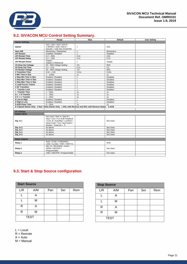
9.2. SIVACON MCU Control Setting Summary. Range Step Default User Setting
Starter Settings
Starter DOL / SD2 / SD3 / DOLR / 2-SPEED / ACB / DOLH / DOLRH / VSD /NO STARTER
1 DOL
Start A/B Momentary / Maintained 1 Momentary
U/V Restart Enabled / Disabled 1 Disabled
U/V Restart Time 0.2 – 200s 0.1s 2.0s
U/V Restart Delay 0.2 – 120s 0.1s 0.2s
U/V Restart Sense Supply / Supply or Reference
1 Supply
UV Drop Out Voltage 50 – 90% Voltage Setting 1% 65%
UV Drop Out Time 0.1 – 0.5s 0.1s 0.2
UV Restart Voltage 50 – 90% Voltage Setting 1% 65%
8 Transition Time 0.04 – 2.00 0.01s 0.20s
8 Min Time In Star 1 – 1200s 1s 1s
8 Stay Min Time in Star Enabled / Disabled 1 Disabled
8 Stay Max Time in Star Enabled / Disabled 1 Disabled
8 Stay Max Time in Star Enabled / Disabled 1 Disabled
8 Load Forces Transit Enabled / Disabled 1 Disabled
8 SC Transition Enabled / Disabled 1 Disabled
% Transfer Lock Enabled / Disabled 1 Disabled
% Transfer Time 1 – 300s 1s 1s
# L -> H Transfer 1 – 250s 1s 1s
# H -> L Transfer 1 – 250s 1s 1s
# Low to High Enabled / Disabled 1 Disabled
# High to Low Enabled / Disabled 1 Disabled
§ ACB Pulse Time 0 – 200s 1s 1s
# 2-Speed Starter Only 8 Star / Delta Starter Only % DOL with Reverse and DOL with Reverse Heater § ACB
I/O Settings
Digital Inputs
Dig_In 1
Not Used / Start A / Start B / Stop / Cont. A or ACB Feedback / Cont. B / Auto/Man / Loc/Rem / Reset Fault / Test / Spd Switch / Restart / External 1 - 5
Not Used
Dig_In 2 As above Not Used
Dig_In 3 As above Not Used
Dig_In 4 As above Not Used
Dig_In 5 As above Not Used
Relay Outputs
Relay 1 RUN / STAR / FORWARD / LOW / CLOSE / TRIP / TRIP FS
RUN
Relay 2 DELTA / REVERSE / HIGH / OPEN / HEATER / Programmable
Not Used
Relay 3 LINE / HEATER / Programmable Not Used
9.3. Start & Stop Source configuration
L = Local R = Remote A = Auto M = Manual
Start Source
L/R A/M Pan Ser Rem
L A
L M
R A
R M
TEST
Stop Source
L/R A/M Pan Ser Rem
L A
L M
R A
R M
TEST
Page 22
SIVACON MCU Technical Manual Document Ref. OMR0101
Issue 1.9, 2019
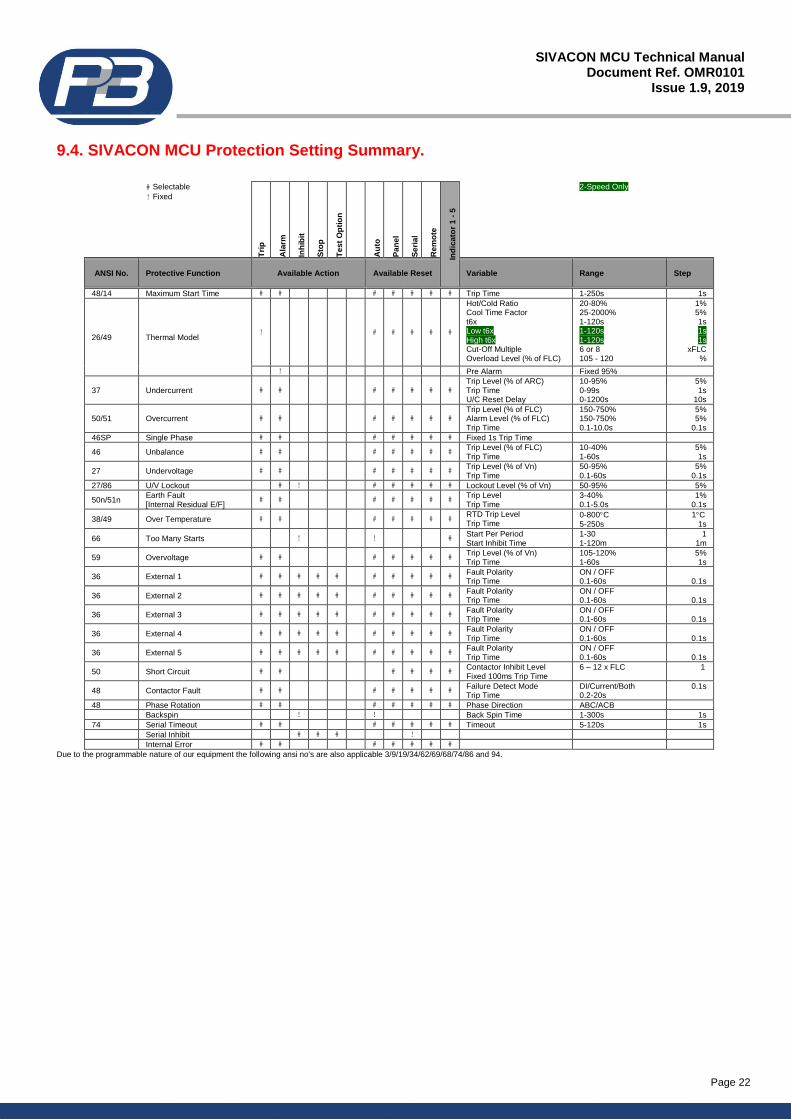
9.4. SIVACON MCU Protection Setting Summary.
# Selectable
! Fixed
Tri
p
Ala
rm
Inh
ibit
Sto
p
Te
st
Op
tio
n
Au
to
Pa
ne
l
Se
ria
l
Rem
ote
Ind
ica
tor
1 -
5
2-Speed Only
ANSI No. Protective Function Available Action Available Reset Variable Range Step
48/14 Maximum Start Time # # # # # # # Trip Time 1-250s 1s
26/49 Thermal Model !
# # # # #
Hot/Cold Ratio Cool Time Factor t6x Low t6x High t6x Cut-Off Multiple Overload Level (% of FLC)
20-80% 25-2000% 1-120s 1-120s 1-120s 6 or 8 105 - 120
1% 5% 1s 1s 1s
xFLC %
! Pre Alarm Fixed 95%
37 Undercurrent # #
# # # # # Trip Level (% of ARC) Trip Time U/C Reset Delay
10-95% 0-99s 0-1200s
5% 1s
10s
50/51 Overcurrent # #
# # # # # Trip Level (% of FLC) Alarm Level (% of FLC) Trip Time
150-750% 150-750% 0.1-10.0s
5% 5%
0.1s
46SP Single Phase # # # # # # # Fixed 1s Trip Time
46 Unbalance # #
# # # # # Trip Level (% of FLC) Trip Time
10-40% 1-60s
5% 1s
27 Undervoltage # # # # # # # Trip Level (% of Vn) Trip Time
50-95% 0.1-60s
5% 0.1s
27/86 U/V Lockout # ! # # # # # Lockout Level (% of Vn) 50-95% 5%
50n/51n Earth Fault [Internal Residual E/F]
# #
# # # # # Trip Level Trip Time
3-40% 0.1-5.0s
1% 0.1s
38/49 Over Temperature # #
# # # # # RTD Trip Level Trip Time
0-800C
5-250s
1C
1s
66 Too Many Starts !
! # Start Per Period Start Inhibit Time
1-30 1-120m
1 1m
59 Overvoltage # #
# # # # # Trip Level (% of Vn) Trip Time
105-120% 1-60s
5% 1s
36 External 1 # # # # #
# # # # # Fault Polarity Trip Time
ON / OFF 0.1-60s
0.1s
36 External 2 # # # # #
# # # # # Fault Polarity Trip Time
ON / OFF 0.1-60s
0.1s
36 External 3 # # # # #
# # # # # Fault Polarity Trip Time
ON / OFF 0.1-60s
0.1s
36 External 4 # # # # #
# # # # # Fault Polarity Trip Time
ON / OFF 0.1-60s
0.1s
36 External 5 # # # # #
# # # # # Fault Polarity Trip Time
ON / OFF 0.1-60s
0.1s
50 Short Circuit # #
# # # # Contactor Inhibit Level Fixed 100ms Trip Time
6 – 12 x FLC
1
48 Contactor Fault # #
# # # # # Failure Detect Mode Trip Time
DI/Current/Both 0.2-20s
0.1s
48 Phase Rotation # # # # # # # Phase Direction ABC/ACB
Backspin ! ! Back Spin Time 1-300s 1s
74 Serial Timeout # # # # # # # Timeout 5-120s 1s
Serial Inhibit # # # !
Internal Error # # # # # # #
Due to the programmable nature of our equipment the following ansi no's are also applicable 3/9/19/34/62/69/68/74/86 and 94.
Page 23
SIVACON MCU Technical Manual Document Ref. OMR0101
Issue 1.9, 2019
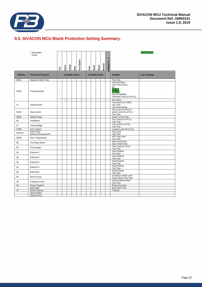
9.5. SIVACON MCU Blank Protection Setting Summary.
# Selectable
! Fixed
Tri
p
Ala
rm
Inh
ibit
Sto
p
Te
st
Op
tio
n
Au
to
Pa
ne
l
Se
ria
l
Rem
ote
Ind
ica
tors
1 -
5
2-Speed Only
ANSI No. Protective Function Available Action Available Reset Variable User Settings
48/14 Maximum Start Time Trip Time
26/49 Thermal Model !
Hot/Cold Ratio Cool Time Factor t6x Low t6x High t6x Cut-Off Multiple Overload Level (% of FLC)
! Pre Alarm
37 Undercurrent
Trip Level (% of ARC) Trip Time U/C Reset Delay
50/51 Overcurrent
Trip Level (% of FLC) Alarm Level (% of FLC) Trip Time
46SP Single Phase Fixed 1s Trip Time
46 Unbalance
Trip Level (% of FLC)
Trip Time
27 Undervoltage Trip Level (% of Vn)
Trip Time
27/86 U/V Lockout ! Lockout Level (% of Vn)
50n/51n Earth Fault [Internal Residual E/F]
Trip Level
Trip Time
38/49 Over Temperature
RTD Trip Level
Trip Time
66 Too Many Starts !
! Start Per Period
Start Inhibit Time
59 Overvoltage
Trip Level (% of Vn)
Trip Time
36 External 1
Fault Polarity Trip Time
36 External 2
Fault Polarity Trip Time
36 External 3
Fault Polarity Trip Time
36 External 4
Fault Polarity Trip Time
36 External 5
Fault Polarity Trip Time
50 Short Circuit
Contactor Inhibit Level
Fixed 100ms Trip Time
48 Contactor Fault
Failure Detect Mode
Trip Time
48 Phase Rotation Phase Direction
Back Spin ! ! Back Spin Time
74 Serial Timeout Timeout
Serial Inhibit !
Internal Error
Page 24
SIVACON MCU Technical Manual Document Ref. OMR0101
Issue 1.9, 2019
10. Serial Settings.
Serial Enabled / Disabled.
This setting allows the user to enable the SIVACON MCU serial communications port. This setting must be set to ‘Enable’ if communication with the relay through any serial link is required. Drive Number. This setting range 1 to 127 with a default setting of 1, identifies the SIVACON MCU unit to the Xcell unit (or any Master device connected to the Data highway) to which the RS485 port(s) are connected. RS485 Baud Rate This setting allows the user to configure the appropriate communications baud rate (9600/19200/38400/57600) such that the SIVACON MCU can communicate effectively on the Data Highway to which it is connected. The RS485 baud rate setting can be changed using the Vision Control software, HMI Operator Panel and the Drive Number/Protocol Programming module (see Appendix 8) Please Note: when the RS485 Protocol setting is set to ‘P&B’ the baud rate setting is fixed to 9600 and cannot be changed. Serial Delay.
The SIVACON MCU may be configured to respond to a request for information from the serial port instantly or after a designated delay. A communications delay may be beneficial to ensure the Master device on the Data Highway receives all information sent back by the SIVACON MCU without enduring data collisions on the network. Fast Scan Words.
A Fast Scan is a system used when operating in conjunction with the XCell Data Concentrator. As the XCell polls relays attached on its network, the fastscan settings allows the user to select important data to be read back faster. The data on the communications link is broken into Fast Scan Data (or Process Critical Data) and Slow Scan or Full Read Data (Electrical Engineering Data). The amount of Fast Scan Data to be sent back to the XCell in response to a request is configurable. This setting has the range 4, 6 or 8 Words. A setting of 4 Words will give 3 Fast Scans. The remaining Word is taken up by the Thermal Capacity. A setting of 6 Words will give 5 configurable Fast Scans and a setting of 8 Words will allow 7 configurable Fast Scans. The configuration of Fast Scan is not necessary unless the SIVACON MCU in used in conjunction with the XCell unit. Fast Scan 1 to 7.
Each FastScan number can be programmed to export important data when requested. This number references an internal address in SIVACON MCU and allows configurable data mapping between units. Typical data could be Average Phase Current, Motor Load and so on. A table of the FastScan reference numbers can be found in Appendix 6 Max Scan Time.
This setting need only be used in order to limit the amount of data traffic on a RS485 network. Dynamic data can change rapidly, this setting allows the SIVACON MCU to limit the number of updates it makes to its Fast Scan values.
Page 25
SIVACON MCU Technical Manual Document Ref. OMR0101
Issue 1.9, 2019
RS485 Protocol. The RS485 serial communications port may be configured to operate using a slave implementation of Modbus RTU® or P&B Engineering’s own protocol “P&B Standard” designed to remove some of the speed issues associated with a function based protocol like Modbus. The RS485 protocol setting can be changed using the Vision Control software, HMI Operator Panel and the Drive Number/Protocol Programming module (see Appendix 8) RS485 Parity. This setting allows the user to set the parity to match that of the host system on the serial link. The options are “Odd”, “Even” and “None” The RS485 parity setting can be changed using the Vision Control software, HMI Operator Panel and the Drive Number/Protocol Programming module (see Appendix 8) Please Note: when the RS485 Protocol setting is set to ‘P&B’ the parity setting is fixed to EVEN and cannot be changed. Serial Timeout Protection. This setting is a protective function and is described in detail in section 15.1.18 Serial Inhibit. This setting is a protective function and is described in detail in section 15.1.19 MODBUS Supported Function Codes
02 – Read Input Status 03 – Read Holding Status 04 – Read Input Registers 05 – Force Single Coil 06 – Preset Single Register
For further details on the actual communication mapping for each of the above codes, please refer to the SIVACON MCU MODBUS communication mapping document.
Page 26
SIVACON MCU Technical Manual Document Ref. OMR0101
Issue 1.9, 2019
11. Motor Settings.
CT Primary.
This setting allows the user to program the primary current rating of the protection class current transformers on the supply phases. It is assumed that all phase current transformers are of the same rating. The SIVACON MCU can be supplied with two CT options, these are 5A or 29A. For direct connection to the SIVACON MCU using these CT’s, then the CT primary setting shall be set to either 5A or 29A respectively, dependent on the rating of the CT sump fitted. Where external current transformers are used or the SIVACON MCU low power CT sump is used, the CT primary should then reflect the CT rating of the CT or external sensor, for example 100:5 CT, the CT primary shall be set to 100A. On selection of the two-speed starter types the ‘CT Primary’ setting will offer two settings, ‘CT Primary (LOW)’ and ‘CT Primary (HIGH)’. This allows connection of two independent sets of current transformers to the SIVACON MCU to monitor current in the fast and slow supply arms to the motor. If only one set of current transformers is used then these two values are set to the same ‘CT Primary’ value. It must be noted that although the Primary values can differ the Secondary values must be the same i.e. 5A or 29A VT Primary.
This setting allows the user to program the primary voltage rating of the voltage transformer (if used). VT Secondary.
This setting allows the user to program the secondary voltage rating of the voltage transformer (if used). The VT Primary and Secondary should be set to the same value if directly connecting the voltage input without a step-down transformer. Full Load Current (FLC).
The FLC is the motors continuous maximum Full Load Current rating as provided in the motor manufacturers data. The settable range is dependent on the ‘CT Primary’ setting. The ‘FLC’ setting enables all protective functions except Undercurrent and Load Increase to be set in terms of a percentage of FLC and enables the SIVACON MCU to display the “Motor Load” in terms of a percentage a FLC. Actual Running Current (ARC). This setting allows the user to program the motors Actual Running Current when supplying a typical load at normal speed. This value is typically less than the motor FLC rating and enables the protective functions (Under Current and Load Increased) to be set in terms of a percentage of this value. Voltage. This should be set to the line voltage of the supply. It is necessary for power calculations and is used for the Under / Overvoltage, Undervoltage Restart and Undervoltage Lockout protection features. KW Sample Period. This setting range 5 to 60 min in steps of 1min determines the period over which a measurement is taken to integrate the Kilowatt Hours value.
Page 27
SIVACON MCU Technical Manual Document Ref. OMR0101
Issue 1.9, 2019
12. Starting Methods.
The SIVACON MCU relay is designed to be used as an intelligent motor starter for LV systems offering comprehensive protection and control features. A number of starting methods are catered for;
Direct On Line (DOL) Direct On Line starting is used for electrically held contactors and allows the motor to be run in one direction only. It applies the full line voltage to the windings immediately upon starting. DOL Starter expects Start A to be used as a hardwired digital input control (momentary or maintained). Output Relay 1 (RUN) will close to pull in the contactor, Cont A digital input should be used if contactor feedback is required through the digital inputs or contactor fault protection is needed. Output 1 will release when stopped or tripped. Typically the inrush current of a 415V motor would be 6x FLC, hence the thermal model protection, t6x. Higher voltage systems generally have lower inrush demands.
Star / Delta 2 (S/D2) This starting technique is typically used to reduce the starting currents normally seen when starting a motor by Direct On Line. By reducing the voltage applied to the motor windings the current is also reduced, as is the starting torque. Care must be taken to ensure the motor can generate enough torque to accelerate on start-up when connected in STAR. Start A is used as the hardwired or remote start signal and closes Output Relay 1. This output is used to pull in a contactor which connects the motor in a star type connection. Cont A is used for feedback and / or contactor fault protection. The Star connection provides root 3 of the system voltage to the motor. This has the effect of limiting the inrush current to 2x (as opposed to 6x for normal 415V drives). Once the current increases and falls below 100% of FLC. Output relay 1 opens. If the current fails to fall below 100% FLC then Output Relay 1 opens after the Max time in star setting. After the transition time Output Relay 2 closes to pull in a contactor connecting the motor in a delta formation. Cont B is used for feedback and / or contactor fault protection of the delta contactor. Once the delta inrush current falls below FLC the SIVACON MCU will consider the motor as running. Maximum Start Time protection functions from the time at which the unit transfers to the delta starter. Output Relay 1 can be held closed for the duration of the Max Time in Star by setting Stay in Star to YES irrespective of the normal current based change-over. Star/Delta 3 (S/D3) For Star / Delta 3 the operation is the same as for the S/D2 type with the exception that Output Relay 3 controls the LINE contactor. Once a Start A command is received both the Star and Line contacts closes, upon transition the Star opens as normal. The line contact remains closed throughout and only released when the drive is stopped or tripped. For both S/D2 and S/D3 the Start Time (statistical data) is determined solely by the time taken from the motor starting in Star formation to the transition to the DELTA connection. Output Relay 1 can be held closed for the duration of the Max Time in Star by setting Stay in Star to YES irrespective of the normal current based change-over.
Page 28
SIVACON MCU Technical Manual Document Ref. OMR0101
Issue 1.9, 2019
Direct On Line Reversing (DOLR) With Direct On Line Reversing Output Relay 1 (FORWARD) is used to control the motor in the forward direction and Output Relay 2 (REVERSE) is used to control the motor in the reverse direction. The full line voltage is applied to the motor windings immediately upon starting in either direction. Start A and Cont A are the start command and feedback for the forward direction. Start B and Cont B are associated with the reverse direction. If an attached load is present when the motor direction is changed then it is possible that the momentum from the load could cause serious mechanical damage to a motor, due to this it is possible to enable a set time inhibit by setting transfer lock to enable and setting a transfer time which will stop the motor from changing direction till the set time has passed. 2-Speed In 2-Speed mode Start A controls Output Relay 1 (LOW) and is used to control the motor in the Low speed with Cont A used as feedback confirmation and / or protection. Start B controls Output Relay 2 (HIGH) and is used to control the motor in the high speed with Cont B used as feedback confirmation and / or protection. This type of starter is used on 2-Speed motors which typically have 2 sets of windings. Different sets of CT’s can be used if the windings are considerably different for one another. To allow for configuration of different CT configurations within the 2-speed motor starter a number of additional settings are available in this mode as follows: -
• CT Primary High (CT Primary Setting for High Speed Mode)
• CT Primary Low (CT Primary Setting for Low Speed Mode)
• FLC High (Full Load Current Setting for High Speed Mode)
• FLC Low (Full Load Current Setting for Low Speed Mode)
• ARC High (Actual Running Current Setting for High Speed Mode)
• ARC Low (Actual Running Current Setting for Low Speed Mode)
• t6x High (Thermal Protection t6x Setting for High Speed Mode)
• t6x Low (Thermal Protection t6x Setting for Low Speed Mode) Example. The high-speed winding is rated at 90 Amps, therefore 100/1A 5p10 2.5VA CT’s are used. If the low speed winding is rated at anything less than 50% of the CT Primary (100A) then a second set of CT’s would be required. In normal 2-Speed mode the motor must be stopped before transferring to the other speed. This transfer between speeds can be partly automated in order to avoid the need to press stop before changing motor speeds. Example. Low to High = Enabled, Low to High Transfer = 5seconds. If running in High speed in order switch to low speed the drive must be stopped using a Stop serial command, a Stop digital input or a Stop panel key press. The drive must then receive a Start A command to run in low speed. In this example, the drive can be started in low speed with Start A, if Start B is pressed the drive stops waits 5 seconds
then automatically starts in high speed. If configured to restart the last running speed before power loss would be used to restart the motor. Air Circuit Breaker (ACB) This starter type must be selected when the motor is controlled by a circuit breaker or mechanically held contactor rather than an electrical held contactor regardless if the motor is in actual fact a DOL starter. Start A drives Output Relay 1 (CLOSE) to close the circuit breaker and start the motor and Output Relay 2 (OPEN) is used to open the circuit breaker and stop the motor. The operation of the CLOSE and OPEN relays is momentary (pulse type) and has a programmable duration. A Digital Input can be programmed to provide Circuit Breaker status feedback, Cont A is renamed as ACB Feedback in ACB mode.
Page 29
SIVACON MCU Technical Manual Document Ref. OMR0101
Issue 1.9, 2019
Direct On Line with Heater (DOLH) This method of starting a motor is for applications where humidity / condensation causes problems in motor windings. Direct on Line with Heater ‘DOLH’ avoids starting a motor when the windings may be damp by energising Output Relay 2 (HEATER) whilst the motor is stopped. In typically situations this output relay would control a contactor feeding a heater embedded in the windings whilst the motor is stopped to evaporate any condensation which may otherwise have developed in the motor. This starter type is similar to Direct on Line ‘DOL’ where Start A is used to drive Output Relay 1 (RUN) to control the motor in one direction only. Output Relay 2 (HEATER) is used to control the Heater embedded in the windings or inject a current in the windings whilst the motor is stopped. Output Relay 2 will automatically energise after 1 hour when the motor is stopped and de-energise when the drive is started. Direct On Line Reversing Heater (DOLRH) This method of starting is the same as that above, but it is used with bi-directional motors. Start A drives Output Relay 1 (FORWARD) to control the motor in the forward direction and Start B drives Output Relay 2 (REVERSE) to control the motor in the reverse direction. Output Relay 3 (HEATER) follows the same function as with DOLH. If an attached load is present when the motor direction is changed then it is possible that the momentum from the load could cause serious mechanical damage to a motor, due to this it is possible to enable a set time inhibit by setting transfer lock to enable and setting a transfer time which will stop the motor from changing direction till the set time has passed. Variable Speed Drive (VSD) Variable Speed Drives allow precise control of the motor speed by varying the frequency or applied voltage to a motor. By the very nature of variable speed drives the initial large “inrush” current typically seen on Direct On Line started motors can be avoided. For all other starter types (except VSD) the SIVACON MCU requires the completion of a successful starting sequence (i.e. the current must exceed 105%FLC and return to or below 100% FLC before the motor is considered as running). This starter type allows the SIVACON MCU to consider the motor as running immediately after a start signal has been issued. Start A drives Output Relay 1 (RUN) to control the motor (which is assumed to be fed from an electrically held contactor). The VSD starter type should also be selected for other starters which do not exhibit inrush characteristics, such as soft starters. For all Starter Types except VSD the successful completion of a starting sequence is required before the motor will be considered running and protection features are enabled. It is recommended the CT’s fed into SIVACON MCU are primary to the VSD inverter.
NOTE: Starter settings under no circumstances should be modified if the device is in service. Following a change of starter settings, a reboot (i.e. power cycle the device by switching off and on the unit) of the SIVACON MCU relay shall be undertaken, prior to putting the device back into service. This is required to ensure that all output relays, related to the starter type chosen have been initialised to their correct state.
Page 30
SIVACON MCU Technical Manual Document Ref. OMR0101
Issue 1.9, 2019
13. Starter Settings.
Starting Method. The Starting method or starter type determines how the connected drive is to be controlled. Whether via a single contactor, a two coil operated breaker etc. Each Starter type is explained in full (see section 12) On selection of some starter types other parameter are also required to achieve correct operation (see section 14) For example, when Star/Delta 2 is selected, values for the transition time behaviour between star and delta closing is required. Start A/B.
This setting, (“Momentary” or “Maintained”) determines the type of digital input signal used to start and run a motor. A momentary input (such as a push button switch) starts the motor when the button is pushed. The motor will remain running after the push button is released. If the motor is started by a momentary switch select “Momentary” in the Start A/B “pop up option screen”. A maintained input starts the motor when the switch changes state from open to closed. The change of state from closed to open stops the motor. If the motor is started by a maintained signal select “Maintained” in the Start A/B option. The motor can be stopped by using the Stop digital input in either Maintained or Momentary modes. In some applications there may be two inputs for running motor control, i.e. one for forward direction and another for reverse (or one for slow and another for high speed). In such applications two switches may be wired to the digital inputs for control of relay A and relay B respectively. The Start A/B setting applies to both switches. They cannot be configured independently. Undervoltage Restart. This setting activates the Undervoltage restart (sometimes referred to as auto re-acceleration) function. A motor must be considered as running prior to voltage or auxiliary supply loss in order for a restart to take effect. The UV Restart facility employed in the SIVACON MCU relay has been designed to comply with the guidelines set-out in the Shell DEP specification DEP 33.67.01.31 The primary function of the UV restart is to detect a voltage dip within the power system when the motor is running and dependent on the duration of the voltage dip either restart (with or without delay) or do not restart the motor following restoration of the system voltage. The SIVACON MCU allows the UV Restart facility to be triggered from voltage dips both on the relay measuring inputs (V1, V2 and V3) and to the relay auxiliary supply. The latter being required for where the relay is powered from the system voltage and not from an Uninterruptable Power Supply (UPS). The UV Restart option within the SIVACON MCU relay can be disabled in this case no restart of the motor will be undertaken regardless of the additional setting parameters, which are used to configure the UV Restart function. The UV Restart is only active if the function is enabled within the SIVACON MCU relay. In some applications it may be desirable to inhibit a restart of a motor for process reasons even though the conditions exist which would ordinarily result in an automated restart taking place. In this case a digital input can be used to either block or allow this restart. (see section 6 “Restart”) UV Restart setting options available within the SIVACON MCU (these exceed the requirements set in DEP specification) Undervoltage Restart Time: 0.2s to 200s in 0.1s steps
This setting determines the allowable voltage dip duration time (the time a relay can be powered off or without nominal voltage) such that if the power is restored or the voltage returns to normal within this time a restart can occur. Voltage loss could be result of upstream supplies changing over, an HV motor starting or some other condition which causes downstream connected drives to either trip on undervoltage protection or cause contactors to drop out.
Page 31
SIVACON MCU Technical Manual Document Ref. OMR0101
Issue 1.9, 2019
Undervoltage Restart Delay: 0s to 120s in 0.1s steps
Once the voltage has been restored to the SIVACON MCU relay and the voltage level measured is above the UV Restart level, then a restart can take place. The restart delay can be used to help control the sequence of a process restart after an outage. This is a settable time to hold off automated start control after voltage restoration. This can be used to prevent an entire bus system of motor starters from trying to reaccelerate at the same time. *(See note below) Restart Sense: Supply – Supply or Reference This setting, which can be set to ‘Supply’ or ‘Supply or Reference’, determines the signal that is examined after a power loss to determine whether an Undervoltage Restart will occur. If it is set to ‘Supply’ then after a power loss and when the supply to the relay is active again a restart will occur. If it is set to ‘Supply or Reference’ the relay will examine if there is voltage on the Bus-bars that supply the motor. Specifically, if the voltage dips below UV Dropout Voltage level for longer than the UV Dropout Time of the line voltage then a Stop is called, if the voltage is restored above the UV Restart level of the line voltage (within the set Restart Time) then the SIVACON MCU will orchestrate the restart. This setting is for the case where the relay is powered from a UPS supply and not from the supplying Bus-bars (i.e. the relay is continually powered during any voltage dip)
When utilising the Aux. Supply for triggering of the UV Restart, the voltage must fall below the device’s minimum operating voltage by at least 15% to guarantee operation. This is to allow for operating tolerances of the power fail detection circuit within the relay. Typical power fail operating voltages are 75Vdc and 53Vac. The actual operating point may vary between devices and over temperature.
U/V Dropout Voltage: 50 to 90% Vn in 1% steps This setting is used to determine the level at which the measured voltage will trigger an undervoltage restart detection. Any of the three phase voltage inputs V1, V2 or V3 or any combination of these voltage inputs dropping below the set level will trigger the undervoltage restart detection. The U/V Dropout Voltage is used in conjunction with the U/V Dropout Time. Only when both conditions have been met will the U/V restart function be called. U/V Dropout Time: 0.1s to 0.5s in 0.1s steps This setting is used to determine the time period for which the measured voltage is below the U/V Dropout Voltage level threshold. The U/V Dropout Time is used in conjunction with the U/V Dropout Voltage. Only when both conditions have been met will the U/V restart function be called. U/V Restart Voltage: 50 to 90% Vn in 1% steps This setting is used to determine the level at which the measured voltage will trigger the restart of the motor following a voltage dip. All three phase voltage inputs V1, V2 and V3 need to be above this level, before a restart can occur. The U/V Restart Voltage is used in conjunction with the U/V Restart Time. Only when both conditions have been met will the U/V restart function be actioned. .
*NOTE: the extended start-up time, which may occur when booting due to reading of the 1 wire memory interface could impact on Undervoltage Restart times, if the restart time is very short. Typical delay introduced by the 1 wire module as around 400ms. The SIVACON MCU device can compensate for this time for restart delays >2.8s, but when restart delay is close to the boot-up time of the SIVACON MCU device <2s, then only limited compensation can be applied, for 2s restart delay, actual restart time will be in the region of 2.2s.
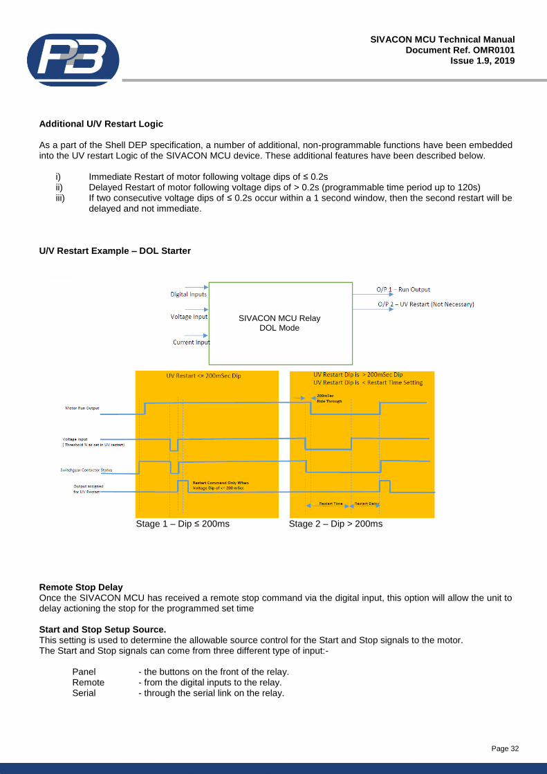
Page 32
SIVACON MCU Technical Manual Document Ref. OMR0101
Issue 1.9, 2019
Additional U/V Restart Logic As a part of the Shell DEP specification, a number of additional, non-programmable functions have been embedded into the UV restart Logic of the SIVACON MCU device. These additional features have been described below.
i) Immediate Restart of motor following voltage dips of ≤ 0.2s ii) Delayed Restart of motor following voltage dips of > 0.2s (programmable time period up to 120s) iii) If two consecutive voltage dips of ≤ 0.2s occur within a 1 second window, then the second restart will be
delayed and not immediate. U/V Restart Example – DOL Starter
Stage 1 – Dip ≤ 200ms Stage 2 – Dip > 200ms Remote Stop Delay Once the SIVACON MCU has received a remote stop command via the digital input, this option will allow the unit to delay actioning the stop for the programmed set time Start and Stop Setup Source. This setting is used to determine the allowable source control for the Start and Stop signals to the motor. The Start and Stop signals can come from three different type of input:- Panel - the buttons on the front of the relay. Remote - from the digital inputs to the relay. Serial - through the serial link on the relay.
SIVACON MCU Relay DOL Mode
Page 33
SIVACON MCU Technical Manual Document Ref. OMR0101
Issue 1.9, 2019
14. Additional Starter Settings.
The following settings are only configurable when specific starter types are selected. # 2-Speed Starter (not DOW)
! Star / Delta 2 & 3
% DOL with Reverse & With Heater
§ ACB Starter
#Low to High Transfer
In order to achieve dual speed control it is necessary to use both Start A and Start B when using hardwired digital inputs. This setting is the motor stopped time when switching between Low speed to High speed using only the Start A and Start B inputs i.e. no issued Stop command. An explanation is given in section 13 #High to Low Transfer
As above, for the application of High to Low speed transfer. #Low to High This setting allows the Low to High Transfer time to be used. If this is set to disabled then speed transfer can only be carried out if the motor is stopped after a Start A command prior to issuing a Start B command #High to Low As above, for the application of High to Low speed transfer. !Transition Time. This setting determines the time period between a change-over from de-energising the Star output to energising the Delta output. !Max Time in Star. This setting, determines the maximum time that the relay can hold the Star output closed. !Stay Max Time in Star If the inrush current falls below 100% of FLC the transition to delta would normally take place. If enabled this setting holds the star output closed for the duration of the Max Time in Star setting !Load Forces Transit If Enabled this setting forces the relay from Star to Delta at 80% FLC regardless of any other star/delta transition settings !SC Transition This setting Increases short circuit current on transition to 15 times FLC, also 100ms before star/delta transition the O/C protection level is increased by two times. After the delta phase transition the short circuit level is maintained for 500ms before returning back to normal.
Page 34
SIVACON MCU Technical Manual Document Ref. OMR0101
Issue 1.9, 2019
%Transfer Lock. Operates an inhibit period between switching from the forward to reverse direction or vice-versa. An attached load may continue to rotate after the supply power is removed, energising in the reverse direction against this momentum could cause serious mechanical damage to a motor. %Transfer Time. This is the settable inhibit time when the transfer lock is used. §ACB Pulse Time. The Close and Open output relays are closed only for the set ACB Pulse time.
15. Protection Settings.
Each protection function is configurable independently of the others. The available action, type of reset, various threshold levels and trip timers for each and every protection function can be found in (section 9.4) The below section describes in detail what each function does and how it operates. Alarm. An Alarm is considered as a high level function. If enabled, and the function activates it will be recorded as part of the alarm history and cause the SIVACON MCU to enter an alarm state; the alarm LED on the HMI if connected and configured will be illuminated. If an output relay is set as Alarm or Alarm FS it will change state with the fault. Trip. A Trip is considered as a high level function. If enabled, and the function activates it will be recorded as part of the trip history and cause SIVACON MCU to enter a trip state; the trip LED on the HMI if connected and configured will be illuminated. If an output relay is set as Trip or Trip FS it will change state with the fault. Even if no output relay is set as Trip the SIVACON MCU will stop the drive by releasing the RUN output (or pulsing the OPEN output). Inhibit. An Inhibit is considered as a high level function. If enabled and the function activates it will display in the Inhibit page. The drive may continue to run but cannot be restarted whilst the inhibit remains, the inhibit LED on the HMI if connected and configured will be illuminated.The Stop open condition will also cause an inhibit preventing the drive from starting unless; the input is closed or the drive is entered into a state whereby the remote stop source can be ignored. It is generally good practice to wire the stop signal through the contactor preventing it from closing whilst the stop is open unless the isolator or main power connector is out of service. Reset. The configuration of the reset allows that particular function to be cleared or reset to a healthy condition providing the condition that caused the fault, alarm or inhibit has been removed. Auto Reset. This option, when enabled, automatically resets the Fault when the situation that caused the trip has been removed. Panel-Reset. This option when selected, allows a reset of a fault to be carried out from the front panel of the relay. Once the fault has cleared, RST will appear in the bottom right of the display scroll screens. Serial-Reset. This option, when Enabled, allows a reset of a fault to be carried out through the serial communications of the relay. Remote-Reset. This option, when Enabled, allows a reset of a fault to be carried out through the digital inputs to the relay. A digital input must be set to Reset Faults and must be closed after the fault condition has been removed in order for the reset to operate.
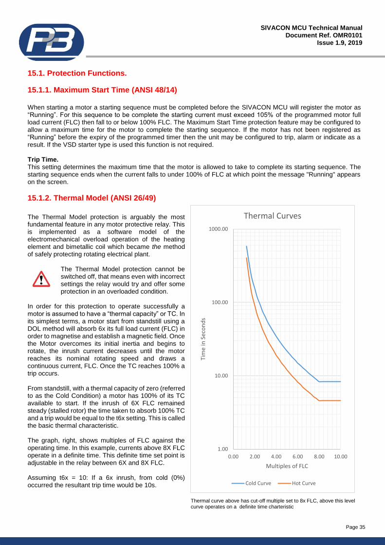
Page 35
SIVACON MCU Technical Manual Document Ref. OMR0101
Issue 1.9, 2019
15.1. Protection Functions.
15.1.1. Maximum Start Time (ANSI 48/14)
When starting a motor a starting sequence must be completed before the SIVACON MCU will register the motor as “Running”. For this sequence to be complete the starting current must exceed 105% of the programmed motor full load current (FLC) then fall to or below 100% FLC. The Maximum Start Time protection feature may be configured to allow a maximum time for the motor to complete the starting sequence. If the motor has not been registered as “Running” before the expiry of the programmed timer then the unit may be configured to trip, alarm or indicate as a result. If the VSD starter type is used this function is not required. Trip Time. This setting determines the maximum time that the motor is allowed to take to complete its starting sequence. The starting sequence ends when the current falls to under 100% of FLC at which point the message "Running" appears on the screen.
15.1.2. Thermal Model (ANSI 26/49)
The Thermal Model protection is arguably the most fundamental feature in any motor protective relay. This is implemented as a software model of the electromechanical overload operation of the heating element and bimetallic coil which became the method of safely protecting rotating electrical plant.
The Thermal Model protection cannot be switched off, that means even with incorrect settings the relay would try and offer some protection in an overloaded condition.
In order for this protection to operate successfully a motor is assumed to have a “thermal capacity” or TC. In its simplest terms, a motor start from standstill using a DOL method will absorb 6x its full load current (FLC) in order to magnetise and establish a magnetic field. Once the Motor overcomes its initial inertia and begins to rotate, the inrush current decreases until the motor reaches its nominal rotating speed and draws a continuous current, FLC. Once the TC reaches 100% a trip occurs. From standstill, with a thermal capacity of zero (referred to as the Cold Condition) a motor has 100% of its TC available to start. If the inrush of 6X FLC remained steady (stalled rotor) the time taken to absorb 100% TC and a trip would be equal to the t6x setting. This is called the basic thermal characteristic. The graph, right, shows multiples of FLC against the operating time. In this example, currents above 8X FLC operate in a definite time. This definite time set point is adjustable in the relay between 6X and 8X FLC. Assuming t6x = 10: If a 6x inrush, from cold (0%) occurred the resultant trip time would be 10s.
Thermal curve above has cut-off multiple set to 8x FLC, above this level curve operates on a definite time charteristic
1.00
10.00
100.00
1000.00
0.00 2.00 4.00 6.00 8.00 10.00
Tim
e in
Sec
on
ds
Multiples of FLC
Thermal Curves
Cold Curve Hot Curve
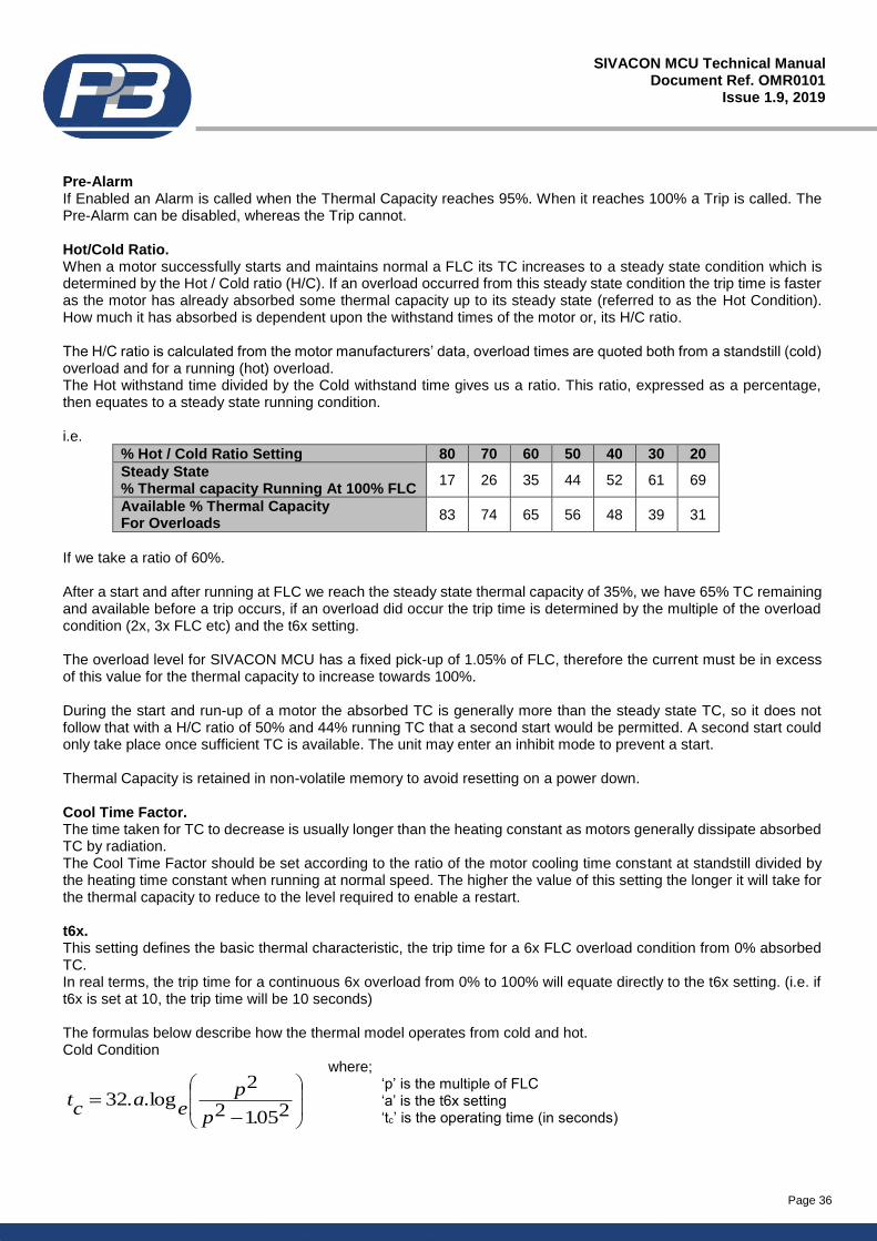
Page 36
SIVACON MCU Technical Manual Document Ref. OMR0101
Issue 1.9, 2019
Pre-Alarm If Enabled an Alarm is called when the Thermal Capacity reaches 95%. When it reaches 100% a Trip is called. The Pre-Alarm can be disabled, whereas the Trip cannot. Hot/Cold Ratio. When a motor successfully starts and maintains normal a FLC its TC increases to a steady state condition which is determined by the Hot / Cold ratio (H/C). If an overload occurred from this steady state condition the trip time is faster as the motor has already absorbed some thermal capacity up to its steady state (referred to as the Hot Condition). How much it has absorbed is dependent upon the withstand times of the motor or, its H/C ratio. The H/C ratio is calculated from the motor manufacturers’ data, overload times are quoted both from a standstill (cold) overload and for a running (hot) overload. The Hot withstand time divided by the Cold withstand time gives us a ratio. This ratio, expressed as a percentage, then equates to a steady state running condition. i.e.
% Hot / Cold Ratio Setting 80 70 60 50 40 30 20
Steady State % Thermal capacity Running At 100% FLC
17 26 35 44 52 61 69
Available % Thermal Capacity For Overloads
83 74 65 56 48 39 31
If we take a ratio of 60%. After a start and after running at FLC we reach the steady state thermal capacity of 35%, we have 65% TC remaining and available before a trip occurs, if an overload did occur the trip time is determined by the multiple of the overload condition (2x, 3x FLC etc) and the t6x setting. The overload level for SIVACON MCU has a fixed pick-up of 1.05% of FLC, therefore the current must be in excess of this value for the thermal capacity to increase towards 100%. During the start and run-up of a motor the absorbed TC is generally more than the steady state TC, so it does not follow that with a H/C ratio of 50% and 44% running TC that a second start would be permitted. A second start could only take place once sufficient TC is available. The unit may enter an inhibit mode to prevent a start. Thermal Capacity is retained in non-volatile memory to avoid resetting on a power down. Cool Time Factor. The time taken for TC to decrease is usually longer than the heating constant as motors generally dissipate absorbed TC by radiation. The Cool Time Factor should be set according to the ratio of the motor cooling time constant at standstill divided by the heating time constant when running at normal speed. The higher the value of this setting the longer it will take for the thermal capacity to reduce to the level required to enable a restart. t6x. This setting defines the basic thermal characteristic, the trip time for a 6x FLC overload condition from 0% absorbed TC. In real terms, the trip time for a continuous 6x overload from 0% to 100% will equate directly to the t6x setting. (i.e. if t6x is set at 10, the trip time will be 10 seconds) The formulas below describe how the thermal model operates from cold and hot. Cold Condition
where; ‘p’ is the multiple of FLC ‘a’ is the t6x setting ‘tc’ is the operating time (in seconds)
−=
20512
2log32
.p
pe
.a.c
t
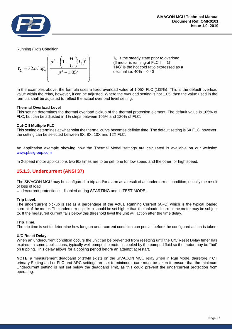
Page 37
SIVACON MCU Technical Manual Document Ref. OMR0101
Issue 1.9, 2019
Running (Hot) Condition
‘IL’ is the steady state prior to overload (If motor is running at FLC IL = 1) ‘H/C’ is the hot cold ratio expressed as a decimal i.e. 40% = 0.40
In the examples above, the formula uses a fixed overload value of 1.05X FLC (105%). This is the default overload value within the relay, however, it can be adjusted. Where the overload setting is not 1.05, then the value used in the formula shall be adjusted to reflect the actual overload level setting. Thermal Overload Level This setting determines the thermal overload pickup of the thermal protection element. The default value is 105% of FLC, but can be adjusted in 1% steps between 105% and 120% of FLC. Cut-Off Multiple FLC This setting determines at what point the thermal curve becomes definite time. The default setting is 6X FLC, however, the setting can be selected between 6X, 8X, 10X and 12X FLC. An application example showing how the Thermal Model settings are calculated is available on our website: www.pbsigroup.com In 2-speed motor applications two t6x times are to be set, one for low speed and the other for high speed.
15.1.3. Undercurrent (ANSI 37)
The SIVACON MCU may be configured to trip and/or alarm as a result of an undercurrent condition, usually the result of loss of load. Undercurrent protection is disabled during STARTING and in TEST MODE. Trip Level. The undercurrent pickup is set as a percentage of the Actual Running Current (ARC) which is the typical loaded current of the motor. The undercurrent pickup should be set higher than the unloaded current the motor may be subject to. If the measured current falls below this threshold level the unit will action after the time delay. Trip Time. The trip time is set to determine how long an undercurrent condition can persist before the configured action is taken. U/C Reset Delay. When an undercurrent condition occurs the unit can be prevented from resetting until the U/C Reset Delay timer has expired. In some applications, typically well pumps the motor is cooled by the pumped fluid so the motor may be “hot” on tripping. This delay allows for a cooling period before an attempt at restart. NOTE: a measurement deadband of 1%In exists on the SIVACON MCU relay when in Run Mode, therefore if CT primary Setting and or FLC and ARC settings are set to minimum, care must be taken to ensure that the minimum Undercurrent setting is not set below the deadband limit, as this could prevent the undercurrent protection from operating.
( )
−
−−
=22
22
05.1
1
log..32p
IC
Hp
aL
ect
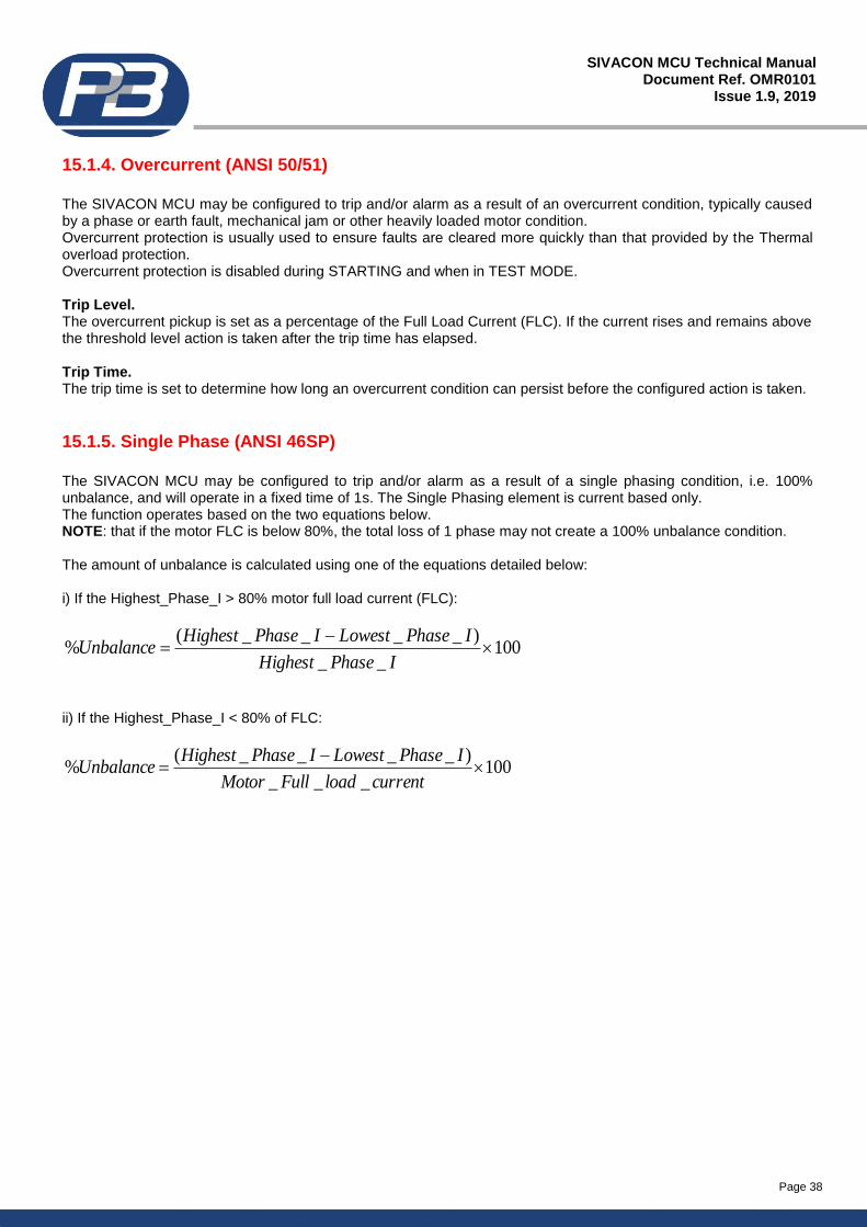
Page 38
SIVACON MCU Technical Manual Document Ref. OMR0101
Issue 1.9, 2019
15.1.4. Overcurrent (ANSI 50/51)
The SIVACON MCU may be configured to trip and/or alarm as a result of an overcurrent condition, typically caused by a phase or earth fault, mechanical jam or other heavily loaded motor condition. Overcurrent protection is usually used to ensure faults are cleared more quickly than that provided by the Thermal overload protection. Overcurrent protection is disabled during STARTING and when in TEST MODE. Trip Level. The overcurrent pickup is set as a percentage of the Full Load Current (FLC). If the current rises and remains above the threshold level action is taken after the trip time has elapsed. Trip Time. The trip time is set to determine how long an overcurrent condition can persist before the configured action is taken.
15.1.5. Single Phase (ANSI 46SP)
The SIVACON MCU may be configured to trip and/or alarm as a result of a single phasing condition, i.e. 100% unbalance, and will operate in a fixed time of 1s. The Single Phasing element is current based only. The function operates based on the two equations below. NOTE: that if the motor FLC is below 80%, the total loss of 1 phase may not create a 100% unbalance condition. The amount of unbalance is calculated using one of the equations detailed below: i) If the Highest_Phase_I > 80% motor full load current (FLC):
100__
)____(%
−=
IPhaseHighest
IPhaseLowestIPhaseHighestUnbalance
ii) If the Highest_Phase_I < 80% of FLC:
100___
)____(%
−=
currentloadFullMotor
IPhaseLowestIPhaseHighestUnbalance
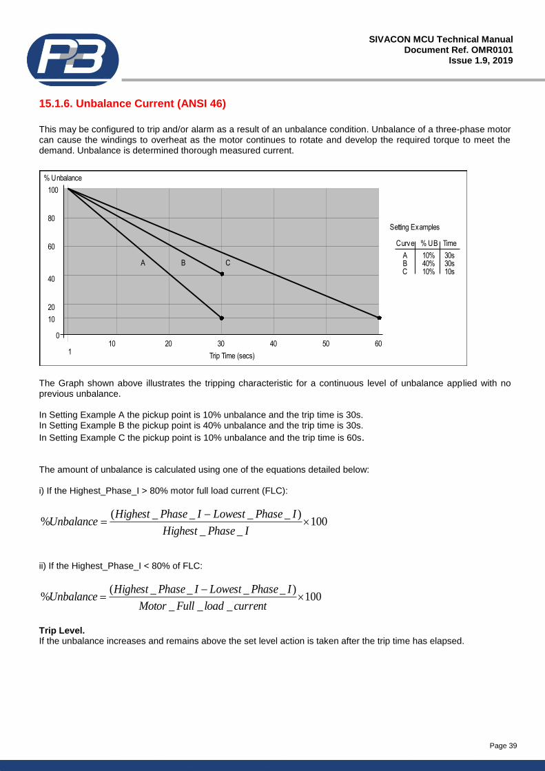
Page 39
SIVACON MCU Technical Manual Document Ref. OMR0101
Issue 1.9, 2019
15.1.6. Unbalance Current (ANSI 46)
This may be configured to trip and/or alarm as a result of an unbalance condition. Unbalance of a three-phase motor can cause the windings to overheat as the motor continues to rotate and develop the required torque to meet the demand. Unbalance is determined thorough measured current.
The Graph shown above illustrates the tripping characteristic for a continuous level of unbalance applied with no previous unbalance. In Setting Example A the pickup point is 10% unbalance and the trip time is 30s. In Setting Example B the pickup point is 40% unbalance and the trip time is 30s.
In Setting Example C the pickup point is 10% unbalance and the trip time is 60s. The amount of unbalance is calculated using one of the equations detailed below: i) If the Highest_Phase_I > 80% motor full load current (FLC):
100__
)____(%
−=
IPhaseHighest
IPhaseLowestIPhaseHighestUnbalance
ii) If the Highest_Phase_I < 80% of FLC:
100___
)____(%
−=
currentloadFullMotor
IPhaseLowestIPhaseHighestUnbalance
Trip Level. If the unbalance increases and remains above the set level action is taken after the trip time has elapsed.
100
80
60
40
20
10
010 20 30 40 50 60
% Unbalance
Trip Time (secs)1
A B C
Setting Examples
Curve % UB Time
ABC
10%40%10%
30s30s10s
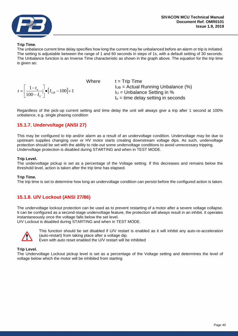
Page 40
SIVACON MCU Technical Manual Document Ref. OMR0101
Issue 1.9, 2019
Trip Time. The unbalance current time delay specifies how long the current may be unbalanced before an alarm or trip is initiated. The setting is adjustable between the range of 1 and 60 seconds in steps of 1s, with a default setting of 30 seconds. The Unbalance function is an Inverse Time characteristic as shown in the graph above. The equation for the trip time is given as:
Regardless of the pick-up current setting and time delay the unit will always give a trip after 1 second at 100% unbalance, e.g. single phasing condition
15.1.7. Undervoltage (ANSI 27)
This may be configured to trip and/or alarm as a result of an undervoltage condition. Undervoltage may be due to upstream supplies changing over or HV motor starts creating downstream voltage dips. As such, undervoltage protection should be set with the ability to ride-out some undervoltage conditions to avoid unnecessary tripping. Undervoltage protection is disabled during STARTING and when in TEST MODE. Trip Level. The undervoltage pickup is set as a percentage of the Voltage setting. If this decreases and remains below the threshold level, action is taken after the trip time has elapsed. Trip Time. The trip time is set to determine how long an undervoltage condition can persist before the configured action is taken.
15.1.8. U/V Lockout (ANSI 27/86)
The undervoltage lockout protection can be used as to prevent restarting of a motor after a severe voltage collapse. It can be configured as a second-stage undervoltage feature, the protection will always result in an inhibit. It operates instantaneously once the voltage falls below the set level. U/V Lockout is disabled during STARTING and when in TEST MODE.
This function should be set disabled if U/V restart is enabled as it will inhibit any auto-re-acceleration (auto-restart) from taking place after a voltage dip. Even with auto reset enabled the U/V restart will be inhibited
Trip Level. The Undervoltage Lockout pickup level is set as a percentage of the Voltage setting and determines the level of voltage below which the motor will be inhibited from starting
1100100
1+−•
−
−= UB
U
u II
tt
Where t = Trip Time IUB = Actual Running Unbalance (%) IU = Unbalance Setting in % tu = time delay setting in seconds
Page 41
SIVACON MCU Technical Manual Document Ref. OMR0101
Issue 1.9, 2019
15.1.9. Earth Fault (ANSI 50n/51n)
The SIVACON MCU may be configured to trip and/or alarm as a result of an EF overcurrent condition. Generally it is desired that earth fault protection be instantaneous although in some applications transient earth fault currents may be seen, and requires a small delay to be imposed to prevent nuisance tripping. In most cases the earth fault protection feature should be set to ensure appropriate coordination with other devices. Depending on the type of system grounding (resistive or solidly earthed) an earth fault current has the potential to be very large. The user must be aware of the maximum earth fault current the system can experience when using the Earth Fault protection feature with a fused contactor. If solidly earthed, the earth fault current may be much higher than the rated current breaking capability of the contactor. An attempt to break a fault current in excess of its rating may cause damage to the equipment. In such applications the user should ensure appropriate coordination between the device and HRC fuses and/or disable the Short Circuit protection feature. Circuit Breakers are typically rated to break the full fault current, Contactors are not. Trip Level. The earth fault pickup is set as a percentage of the EF CT Primary. If the current rises and remains above the threshold level action is taken after the trip time has elapsed. Trip Time.
The trip time is set to determine how long an earth fault condition can persist before the configured action is taken.
15.1.10. Over Temperature (ANSI 38/49)
The SIVACON MCU may be configured to trip, alarm and/or indicate as a result of an over temperature condition, as seen by an external temperature probe. It can provide protection or indication of excessive heating as a result of a lack of ventilation/cooling, negative sequence currents, overvoltage and other conditions which may not be detected by the Thermal Model. The single temperature input allows the connection of RTD (Resistance Temperature Device – type PT100) probes only. When the Over Temperature function is enabled the device will alarm, if enabled, as a result of a Short or Open circuited temperature probe. In either case no trip, regardless of the trip setting will be generated only an alarm condition will be indicated. RTD Trip Level. This setting determines the temperature level at which the configured action should be taken. Trip Time. This setting determines the delay between the unit registering and maintaining a threshold pick-up and the resulting configured action.
Page 42
SIVACON MCU Technical Manual Document Ref. OMR0101
Issue 1.9, 2019
15.1.11. Too Many Starts (ANSI 66)
The SIVACON MCU will inhibit and can be configured to indicate as a result of too many starts occurring. It is often desirable to prevent multiple starts of a drive particularly if it is the cause of stability problems on the power system. Reset type is fixed to auto. The inhibit will auto-reset after the selected time delay has elapsed. Only then can a start can then be made. Starts per Hour. The number of allowable starts in one hour before actively inhibiting further starts from being made. Start Inhibit Time. Once the number of starts has been exceeded, the start inhibit time will inhibit the relay and prevent the motor from being restarted until the timer has expired (remaining time left from 1 hour + Start Inhibit Time), at which point the number of starts permitted per hour is also reset. Example Starts per Hour is set to 3 and Start Inhibit Time is set to 10 min. The motor starts run’s for 10 minutes then stops, then 10 minutes later starts again and runs for 5 minutes. 20 Minutes later the motor starts again and the relay Inhibits. In this case the Inhibit will reset in 25 minutes 1 hour – 45 minutes (time elapsed from the first start to the 3rd start) + 10 minutes (Start Inhibit Time)
15.1.12. Overvoltage (ANSI 59)
The SIVACON MCU may be configured to trip, alarm and/or indicate as a result of an overvoltage condition. Overvoltage protection is disabled during STARTING and when in TEST MODE. Trip Level. The overvoltage pickup is set as a percentage of the Voltage setting. If this increases and remains above the threshold level action is taken after the trip time has elapsed.
Trip Time. The trip time is set to determine how long an overvoltage condition can persist before the configured action is taken.
15.1.13. External 1 to 5 (ANSI 36)
The external faults are digital input based, configurable action inputs. Up to 5 are available and bring a flexible PLC approach to the normal protective functionality. Each is independently configurable and can be used to provide permissive interlocking or process commands in addition to the normal Start and Stop functions. Action. The action can be set to any combination of Trip and/or Alarm as a result of an external fault. Stop/Inhibit This allows the external fault to be configured to imitate an Inhibit and Stop as a result of an external fault The function can also be set to Test option which allows the function to be de-active when in the test mode. Polarity. This option determines the polarity of the digital input that activates this function. 'OFF=Fault' (typically fed from a NC contact), means that when the digital input is Open the External Fault will action. 'ON=Fault' (typically fed from a NO contact), means that when the digital input is Closed the External Fault will action. Trip Time. Determines the time an external input can remain in its fault state before any action is taken.
Page 43
SIVACON MCU Technical Manual Document Ref. OMR0101
Issue 1.9, 2019
15.1.14. Short Circuit (ANSI 50)
The Short Circuit protection feature can be set to Trip and/or Alarm indication on a result of a short circuit. This provides the user with added protection as it provides a fixed instantaneous trip (<100ms) at a fixed phase current setting of 10x FLC. When Short circuit is set to Trip and/or Alarm the contact Inhibit Level setting is de-active, if the short circuit is set to disabled then the contact Inhibit Level setting is active. This will inhibit any current based trips that breach the “contactor Inhibit level”. Exception to this is the Thermal Trip which will always trip. Contact Inhibit Level This setting can be set from 8 to 12 xFLC in steps of 1. This enables blocking of all current based protection, with the exception of the Thermal Model if the current should exceed the set level of 8 to 12 xFLC, thereby allowing fuses to blow instead of opening the contactor/breaker
Note: Contactor Inhibit is only active if “Short Circuit” is set to disable Care should be taken when setting Short Circuit or using Contactor Inhibit. If FLC setting is greater than 100%, it can be possible that the CT measurement will saturate before the 10 or 12X FLC levels have been reached, therefore, additional review of maximum settings will be required for FLC setting values over 100%
15.1.15. Contactor Fault (ANSI 48)
Contactor Fault protection is determined from the digital input status of Cont A and Cont B inputs to confirm run/close, stop/open and trip commands (ACB Feedback when in ACB starter type). If the feedback fails to confirm a sent signal via the output relays the configured action for this function will take place. Regardless whether Start A/B is set to momentary or maintained, feedback signals are always maintained signals. Current detection is used only to determine if a welded contact is present (i.e. current is still flowing although open or trip command has been issued) The current level used to detect welded contactor is >10% In. Failure Detection Mode. Feedback: Feedback signal for digital input to confirm run/close, stop/open and trip commands. Current: Determines run/close, stop/open and trip commands via presence of current Feedback & Current: Combination of the above two. Trip Time. Determines the allowable propagation time of a feedback signal before any action is taken.
15.1.16. Phase Rotation (ANSI 47)
The direction of rotation of a motor is determined by the connection of the 3 phase supply. In some applications it may be necessary to prevent the motor accelerating in the opposite direction or with incorrect phase connections. The SIVACON MCU may be configured to trip, alarm and/or indicate as a result of an incorrect phase rotation within 25 AC crossover cycles at 50Hz (0.25s). Phase Rotation is only enabled during the STARTING sequence and when current is above 1.5 x FLC Direction.
The configurable phase rotation can be ‘ABC’ (00 1200 2400) or ‘ACB’ (00 2400 1200) this determines the preference. If the phase relationship is anything other than this the configured action is taken.
Page 44
SIVACON MCU Technical Manual Document Ref. OMR0101
Issue 1.9, 2019
15.1.17. Back Spin (ANSI 86)
After a motor stop a fixed inhibit will be active for the set period. In certain applications such as well pumping where a motor is pumping against gravity it is often good practice to inhibit a motor starting for a moment prior to a trip or stop. In such applications when the motor is stopped the fluid may rotate the shaft in the opposite direction as it settles. An Anti-Backspin timer can help to prevent undesired mechanical stresses on the machine if a start was made against the downward force. Backspin Time. Sets the length of the inhibit time after a stop before a start can be made.
15.1.18. Serial Timeout (ANSI 74)
For a programmed period of inactivity on the rear communication port the unit can be configured to Trip and/or Alarm in this event. This protection option relates only to the dedicated RS485 communication port only. It is worth noting that the SIVACON MCU device is slave to any host system, the unit will not send information via the serial port unless it has been requested by a master device. Trip Time The trip time is set to determine how long an inactive condition can persist before the configured action is taken.
15.1.19. Serial Inhibit.
The serial inhibit protection function inhibits a motor from starting, stop a motor running or can be configured to stop a motor and inhibit further starting as a result of a serial command. This inhibit will be registered by the SIVACON MCU as an inhibit condition. This protection feature allows remote stations (control rooms) to inhibit motor starts via the communications port to lockout and prevent local control of the motor. The Serial Inhibit protection feature may only be disabled by writing to the correct register using the serial port. i.e. The inhibit function may not be disabled via remote switches or from the front panel. The Serial Inhibit register address may be found in both the Modbus and P&B Network Gold Communications Memory Map Document.
15.1.20. Internal Error.
The SIVACON MCU incorporates an internal software and hardware watchdog feature to monitor the integrity of both on board hardware and software systems. This feature may be configured to indicate as a result of any registered problems. If a problem with the hardware or software is located during the error check routines the SIVACON MCU will generate an error code (or diagnostic status) which will be stored in the non-volatile memory of the SIVACON MCU. If an internal error has occurred the SIVACON MCU will initiate a safe lockout state, whilst in the lockout state the PRIMACON will disable all output relay contacts and limited access to the RS485 bus communication will be available to prevent control commands and other functions from being activated. Internal diagnostics are run at start/power-up and when the unit is online. The SIVACON MCU will attempt to reboot or reset the internal hardware in an attempt to auto-recover the fault or failure. If the auto-correct has been successful, and no further internal errors have been detected the lockout state will be reset after 60 seconds. If the auto-correct has not been successful, the relay will remain in the lockout state.
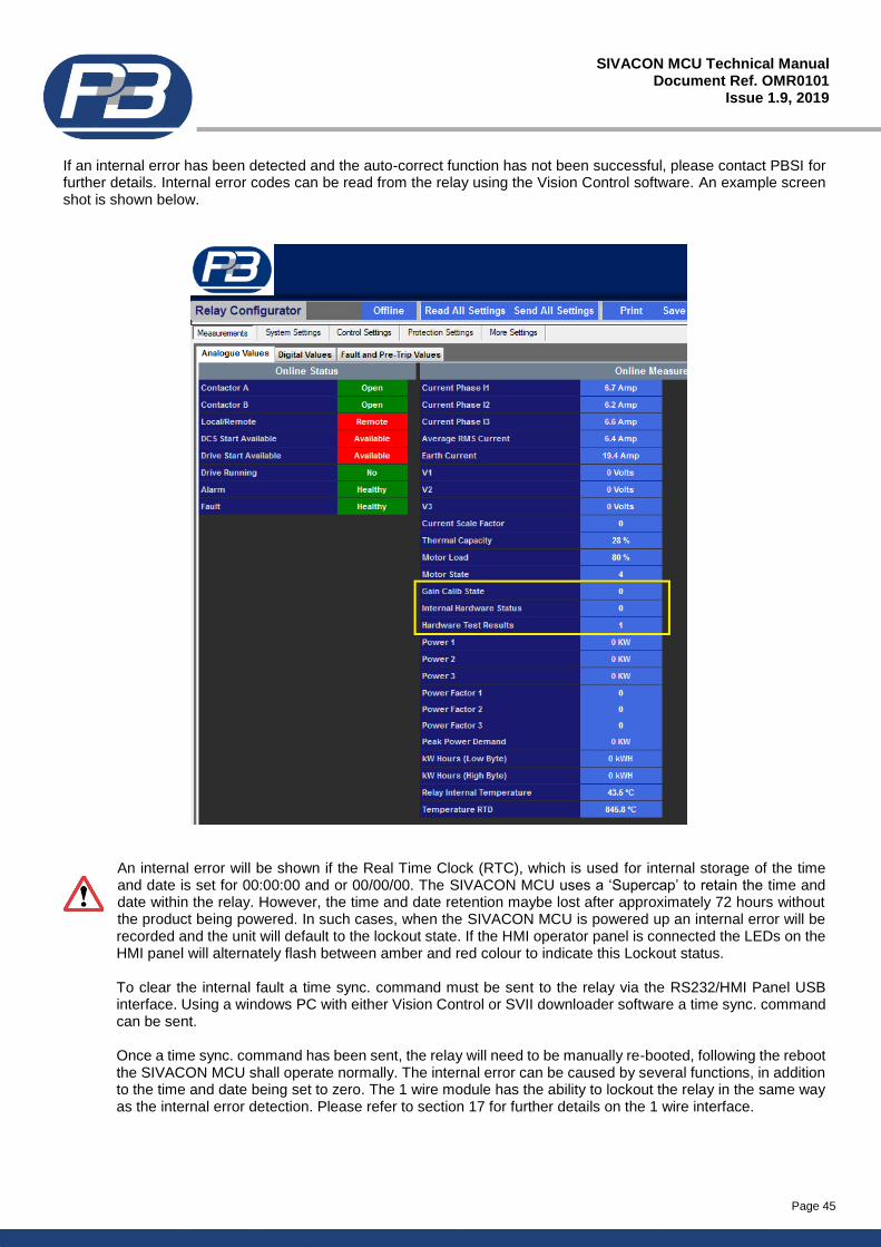
Page 45
SIVACON MCU Technical Manual Document Ref. OMR0101
Issue 1.9, 2019
If an internal error has been detected and the auto-correct function has not been successful, please contact PBSI for further details. Internal error codes can be read from the relay using the Vision Control software. An example screen shot is shown below.
An internal error will be shown if the Real Time Clock (RTC), which is used for internal storage of the time and date is set for 00:00:00 and or 00/00/00. The SIVACON MCU uses a ‘Supercap’ to retain the time and date within the relay. However, the time and date retention maybe lost after approximately 72 hours without the product being powered. In such cases, when the SIVACON MCU is powered up an internal error will be recorded and the unit will default to the lockout state. If the HMI operator panel is connected the LEDs on the HMI panel will alternately flash between amber and red colour to indicate this Lockout status. To clear the internal fault a time sync. command must be sent to the relay via the RS232/HMI Panel USB interface. Using a windows PC with either Vision Control or SVII downloader software a time sync. command can be sent. Once a time sync. command has been sent, the relay will need to be manually re-booted, following the reboot the SIVACON MCU shall operate normally. The internal error can be caused by several functions, in addition to the time and date being set to zero. The 1 wire module has the ability to lockout the relay in the same way as the internal error detection. Please refer to section 17 for further details on the 1 wire interface.
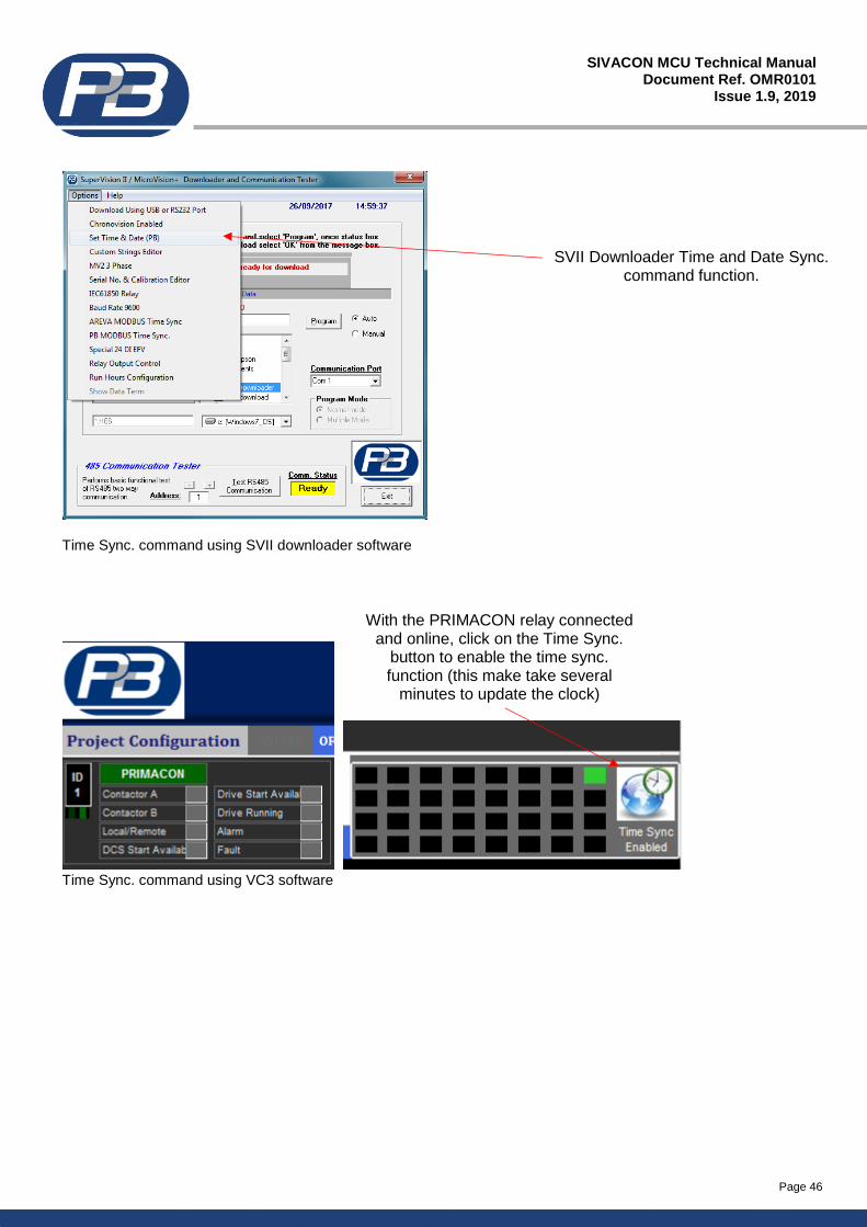
Page 46
SIVACON MCU Technical Manual Document Ref. OMR0101
Issue 1.9, 2019
SVII Downloader Time and Date Sync. command function.
With the PRIMACON relay connected and online, click on the Time Sync.
button to enable the time sync. function (this make take several
minutes to update the clock)
Time Sync. command using SVII downloader software
Time Sync. command using VC3 software
Page 47
SIVACON MCU Technical Manual Document Ref. OMR0101
Issue 1.9, 2019
16. System Settings.
Time Sync Delay. (Only for use with Chronovision)
Chronovision is a GPS based device which sits on the RS485 network and synchronises the time and date of each connected unit. This delay prevents immediate updating of the RTC. LED A - F. This setting determines the function of the LED’s A-F on the SIVACON MCU HMI panel. Two options exist, LEDs A-F are programmable, which allows each LED to have its own function assigned (taken from a pre-defined list) along with the behaviour and colour of that particular LED related to the assigned function. The second option is for the LEDs to be pre-configured as a bar graph displaying Motor Load (ML). LED descriptions shown below. LED A = <25% ML LED B = <50% ML LED C = <75% ML LED D = <100% ML LED E = >105% ML LED F = >150% ML This setting is only applicable for SIVACON MCU units connected to a HMI panel.
Page 48
SIVACON MCU Technical Manual Document Ref. OMR0101
Issue 1.9, 2019
17. External Memory Storage (1-Wire Interface).
The SIVACON MCU relay can be used in conjunction with a dedicated 1 Wire Memory Module interface. This allows the SIVACON MCU’s internal non-volatile memory to be ‘cloned’ via an external module. The philosophy behind this external memory storage is to allow for a simple exchange of removable starter or feeder modules within a switchboard to be relocated or replaced within or between switchgear panels without the need for operator to have access to relay programming software or relay installation manuals. This in turn can vastly reduce the mean time to repair (MTTR). The External memory module shall reside within each of the switchgear starter or feeder locations, this then is used to retain the exact settings required for that particular starter or feeder location including Tag/ID information. The external memory module, when fitted to the SIVACON MCU relay has two basic modes of operation, these are: - Power-Up Operation Following a power-up operation of the SIVACON MCU relay the 1 wire memory module interface is accessed to see if a valid module is connected. If no module is detected, then the SIVACON MCU relay shall proceed with its normal start-up sequence. Where a valid memory module is detected, a Memory Compare Check is initially performed. This function checks the 1 wire memory module status, based on the data read back one of four conditions will be met, as detailed below. The action taken by the SIVACON MCU relay is shown for each of the four conditions.
i) The 1 wire memory module is blank (device is blank or no valid data present) Where a blank 1 wire memory device is detected, the SIVACON MCU device will immediately default to the “Lockout” mode. The HMI Operator Panel, if connected, will continually flash all bank A-F LEDs in a red colour to indicate this Lockout status. The 1 wire memory status communication data, can be read via the RS232 port only, due to the RS485 communication port being inhibited.
ii) The 1 wire memory module settings do not match with the settings in the SIVACON MCU device
Where the settings between the 1 wire module and the SIVACON MCU device do not match. The 1 wire module takes priority, and the settings stored within the 1 wire memory module will be copied directly to the SIVACON MCU internal memory. Once the settings have been transferred, the SIVACON MCU device will immediately default to the “Lockout” mode. The HMI Operator Panel, if connected, will continually flash all bank A-F LEDs in an amber colour to indicate this Lockout status. The 1 wire memory status communication data, can be read via the RS232 port only, due to the RS485 communication port being inhibited.
iii) The 1 wire memory locations are out of there allowed ranges (bounds check) Where a read error or bounds error is detected, the SIVACON MCU device will immediately default to the “Lockout” mode. The HMI Operator Panel, if connected, will continually flash all bank A-F LEDs in an amber colour to indicate this Lockout status. The 1 wire memory status communication data, can be read via the RS232 port only, due to the RS485 communication port being inhibited. iv) The 1 wire memory settings match those of the SIVACON MCU settings (compare test passed) If this case the SIVACON MCU will boot normally with no LED indications being given to the HMI Operator Panel.
The sequence above will be repeated for each power-up cycle of the SIVACON MCU relay.
NOTE: should a ‘Lockout’ condition be activated by the SIVACON MCU device due to a failure of the 1 wire memory module read/write then the relay output contacts of the SIVACON MCU device and the RS485 serial communication will be inhibited to prevent operation of the equipment, both locally and remotely and to prevent any bus corruption caused by having the same serial address on the communication bus network.
Page 49
SIVACON MCU Technical Manual Document Ref. OMR0101
Issue 1.9, 2019
Normal Operation An internal switch within the SIVACON MCU device isolates the 1 wire interface during normal operation. At this time the external 1 wire memory module is dormant and is not integral to the relays operation. The 1 wire interface will only be activated should a command operation be issued, serial bus address change, erase command or a copy settings command. .
NOTE: the extended start-up time, which may occur when booting due to reading of the 1 wire memory interface could impact on Undervoltage Restart times, if the restart time is very short. Typical delay introduced by the 1 wire module as around 400ms. The SIVACON MCU device can compensate for this time for restart delays >2.8s, but when restart delay is close to the boot-up time of the SIVACON MCU device <2s, then only limited compensation can be applied, for 2s restart delay, actual restart time will be in the region of 2.2s.
1 Wire Memory Module Connection The 1 wire memory module is polarity sensitive. If the module is connected with the incorrect polarity, the 1 wire memory module will not be operable. During power-up of the relay, the 1 wire memory module will not be read correctly, and as a result the SIVACON MCU device will immediately default to the “Lockout” mode. The HMI Operator Panel, if connected, will continually flash all bank A-F LEDs in an amber colour to indicate this Lockout status. The 1 wire memory status communication data, can be read via the RS232 port only, due to the RS485 communication port being inhibited.
17.1. Programming the 1-Wire Interface.
Programming of the 1 Wire Memory Module can be achieved using the SIVACON MCU relay along with the Vision Control software package. Connect the SIVACON MCU relay to the 1 Wire interface module to be programmed. The SIVACON MCU, via either the RS232 or RS485 serial communication port shall be connected to a Windows based PC running the Vision Control software. The required settings for the 1 wire module, shall firstly be programmed into the SIVACON MCU relay. Once all settings have been configured, an ‘Erase’ command shall be issued to the 1 Wire module using the Vision Control software, following a successful erase command the ‘Copy SIVACON MCU Settings’ command shall be given. This, if successful, will copy all settings from the SIVACON MCU internal memory into the 1 Wire module. See section 17.2 for further information on sending commands direct to the relay via the communication port. The HMI operator panel, SIVACON MCU Programming Module or RS232 interface can initiate a 1 Wire memory module write. This is automatically performed within the SIVACON MCU relay if a change in the serial bus address is performed. Only the serial bus address setting is written, this shall complete in less than 1 second. Following an ‘Erase’ command, the SIVACON MCU will attempt to erase the data within the 1 wire memory module. If the HMI Operator Panel is connected, the erase process will be shown on the LED bank A-F, with all LEDs flashing green during the erase process. If the erase command was successful, the SIVACON MCU device will immediately default to the “Lockout” mode. The HMI Operator Panel, if connected, will continually flash all bank A-F LEDs in a red colour to indicate this Lockout status. If the erase command fails to complete correctly, the SIVACON MCU device will immediately default to the “Lockout” mode. The HMI Operator Panel, if connected, will continually flash all bank A-F LEDs in an amber colour to indicate this Lockout status and failed erase process. The status of the erase command can be monitored through the communication port, see section 17.2 for further details. Following a ‘Copy Settings’ command, the SIVACON MCU will attempt to copy the data from the SIVACON MCU device to the 1 wire memory module. If the HMI Operator Panel is connected, the copy process will be shown on the LED bank A-F, with all LEDs flashing green during the copy process. If the copy command was successful, the SIVACON MCU device will immediately resume its normal operation and the HMI Operator Panel, if connected will revert back to its pre-programmed LED status. If the copy command fails to complete correctly, the SIVACON MCU device will immediately default to the “Lockout” mode. The HMI Operator Panel, if connected, will continually flash all bank A-F LEDs in an amber colour to indicate this Lockout status and failed copy process. The status of the copy command can be monitored through the communication port, see section 17.2 for further details.
Page 50
SIVACON MCU Technical Manual Document Ref. OMR0101
Issue 1.9, 2019
NOTE: Should a ‘Lockout’ condition be activated by the SIVACON MCU device due to a failure of the 1 wire memory module read/write then the relay output contacts of the SIVACON MCU device and the RS485 serial communication will be inhibited to prevent operation of the equipment, both locally and remotely and to prevent any bus corruption caused by having the same serial address on the communication bus network.
17.2. 1-Wire Interface Communication Status and Programming Commands
The status of the 1 Wire memory interface can be read via the RS485 communication port. The information contained within the status word provides relevant status of the 1 Wire interface including connection status, read/write status, and error status. The communication memory address for 1 Wire Interface can be found at the following address: -
Communication Protocol Function Code Memory Address
P&B Protocol 0x02 0x96
MODBUS RTU Protocol 0x04 0x75
The table below shows the status word of the 1 Wire memory interface.
1 Wire Status register (bit number) Description (bit active i.e. = 1)
Bit 0 (d0) 1 Wire Module Disconnected
Bit 1 (d1) 1 Wire Module Update in Progress
Bit 2 (d2) Relay Lockout (due to data mismatch or write error)
Bit 3 (d3) Settings have been Successfully Updated
Bit 4 (d4) Drive Number has been Successfully Updated
Bit 5 (d5) 1 Wire Module is Blank (has been erased)
Bit 6 (d6) 1 Wire Settings are Corrupted (CRC mismatch)
Bit 7 (d7) 1 Wire Settings do not Match with SIVACON MCU Internal Settings
Bit 8 (d8) 1 Wire Module Not Responding Correctly (hardware fault)
Bit 9 (d9) 1 Wire Bounds Check Failed (setting outside the allowed range)
Communication 1 Wire Control Commands Detailed below are the communication commands for the following operations: -
- Erase Command - Copy SIVACON MCU Internal Settings to the 1 Wire Module
Erase Command
Comms. Protocol Function Code ID of Data Data Length
P&B Protocol 0x28 0x96 0x01
Example P&B Command – Serial/Bus Address = 1 (refer to P&B protocol document for further information) 5A 01 01 28 96 CE 76
Comms. Protocol Function Code Coil Address Data
MODBUS RTU Protocol 0x05 0x112 0xFF
Example MODBUS Command – Serial/Bus Address = 1 (refer to MODBUS protocol document for further information) 01 05 01 12 FF 00 2D C3
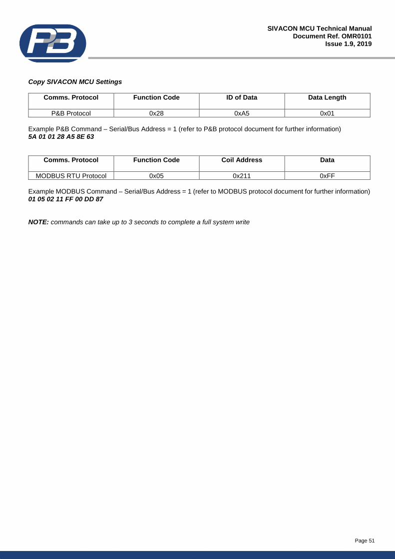
Page 51
SIVACON MCU Technical Manual Document Ref. OMR0101
Issue 1.9, 2019
Copy SIVACON MCU Settings
Comms. Protocol Function Code ID of Data Data Length
P&B Protocol 0x28 0xA5 0x01
Example P&B Command – Serial/Bus Address = 1 (refer to P&B protocol document for further information) 5A 01 01 28 A5 8E 63
Comms. Protocol Function Code Coil Address Data
MODBUS RTU Protocol 0x05 0x211 0xFF
Example MODBUS Command – Serial/Bus Address = 1 (refer to MODBUS protocol document for further information) 01 05 02 11 FF 00 DD 87 NOTE: commands can take up to 3 seconds to complete a full system write
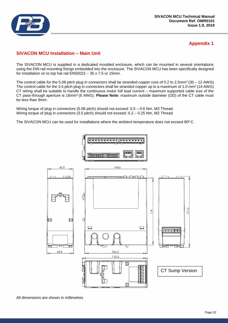
Page 52
SIVACON MCU Technical Manual Document Ref. OMR0101
Issue 1.9, 2019
Appendix 1
SIVACON MCU Installation – Main Unit
The SIVACON MCU is supplied in a dedicated moulded enclosure, which can be mounted in several orientations using the DIN rail mounting fixings embedded into the enclosure. The SIVACON MCU has been specifically designed for installation on to top hat rail EN50022 – 35 x 7.5 or 15mm. The control cable for the 5.08 pitch plug in connectors shall be stranded copper core of 0.2 to 2.5mm2 (30 – 12 AWG) The control cable for the 3.5 pitch plug in connectors shall be stranded copper up to a maximum of 1.0 mm2 (14 AWG) CT wiring shall be suitable to handle the continuous motor full load current – maximum supported cable size of the CT pass-through aperture is 16mm2 (6 AWG). Please Note: maximum outside diameter (OD) of the CT cable must be less than 9mm. Wiring torque of plug in connectors (5.08 pitch) should not exceed: 0.5 – 0.6 Nm, M3 Thread Wiring torque of plug in connectors (3.5 pitch) should not exceed: 0.2 – 0.25 Nm, M2 Thread The SIVACON MCU can be used for installations where the ambient temperature does not exceed 800 C.
All dimensions are shown in millimetres
CT Sump Version
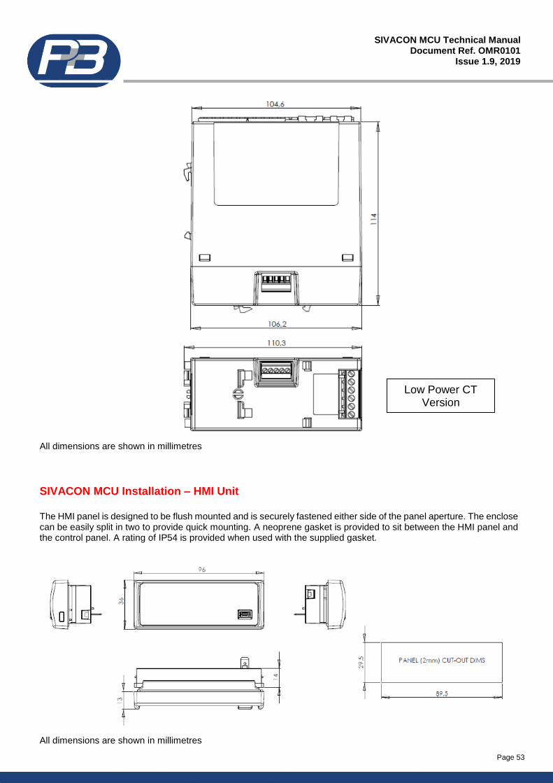
Page 53
SIVACON MCU Technical Manual Document Ref. OMR0101
Issue 1.9, 2019
All dimensions are shown in millimetres
SIVACON MCU Installation – HMI Unit
The HMI panel is designed to be flush mounted and is securely fastened either side of the panel aperture. The enclose can be easily split in two to provide quick mounting. A neoprene gasket is provided to sit between the HMI panel and the control panel. A rating of IP54 is provided when used with the supplied gasket.
All dimensions are shown in millimetres
Low Power CT Version
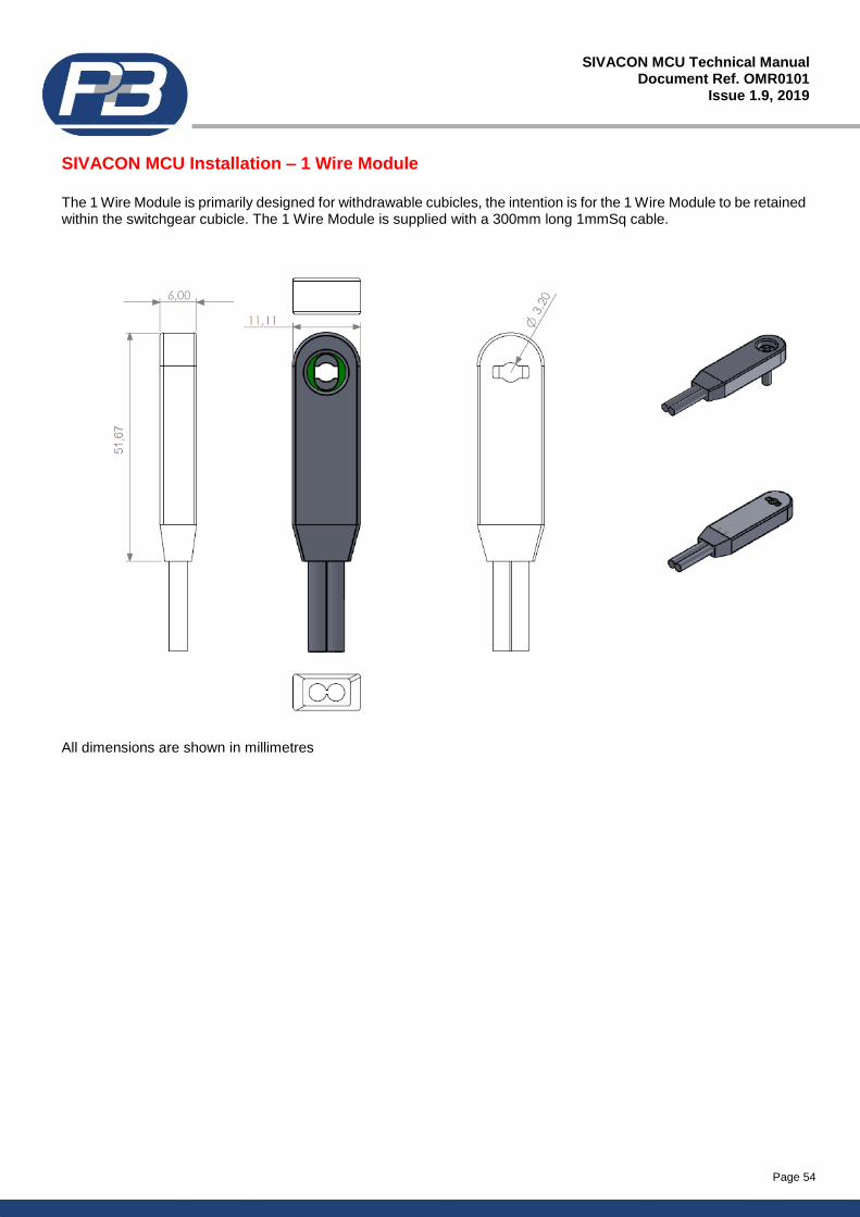
Page 54
SIVACON MCU Technical Manual Document Ref. OMR0101
Issue 1.9, 2019
SIVACON MCU Installation – 1 Wire Module
The 1 Wire Module is primarily designed for withdrawable cubicles, the intention is for the 1 Wire Module to be retained within the switchgear cubicle. The 1 Wire Module is supplied with a 300mm long 1mmSq cable.
All dimensions are shown in millimetres
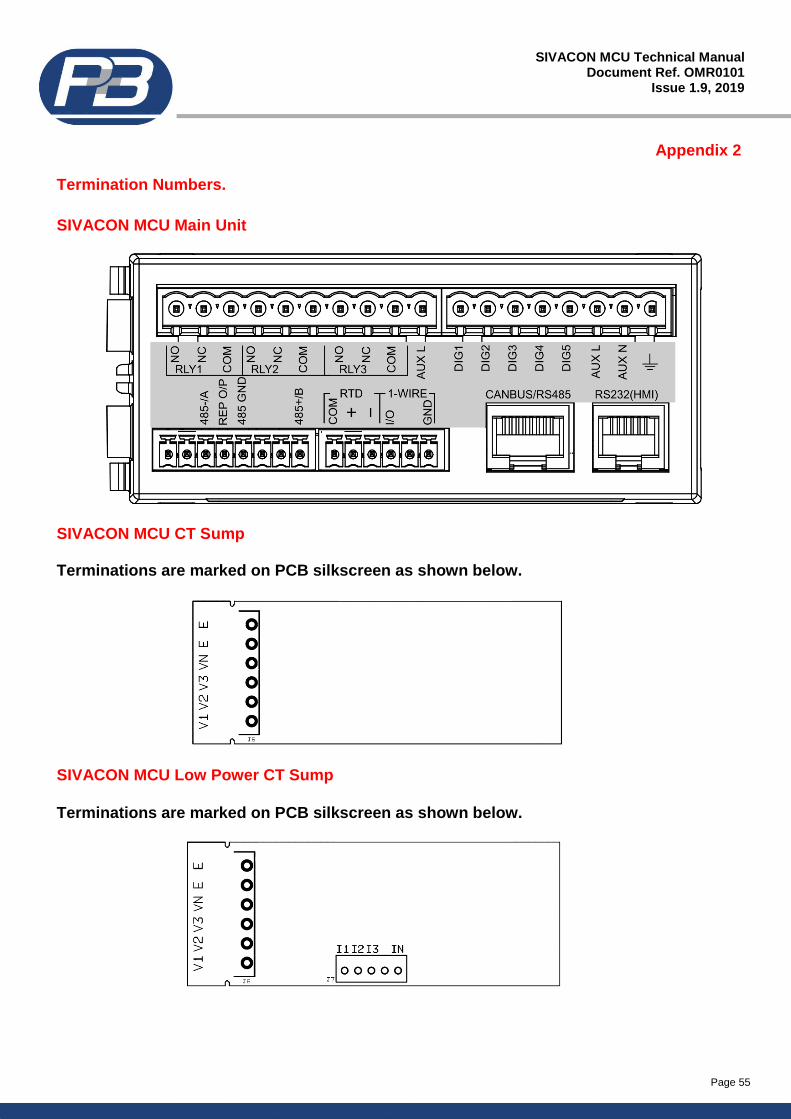
Page 55
SIVACON MCU Technical Manual Document Ref. OMR0101
Issue 1.9, 2019
Appendix 2
Termination Numbers.
SIVACON MCU Main Unit
SIVACON MCU CT Sump Terminations are marked on PCB silkscreen as shown below.
SIVACON MCU Low Power CT Sump
Terminations are marked on PCB silkscreen as shown below.
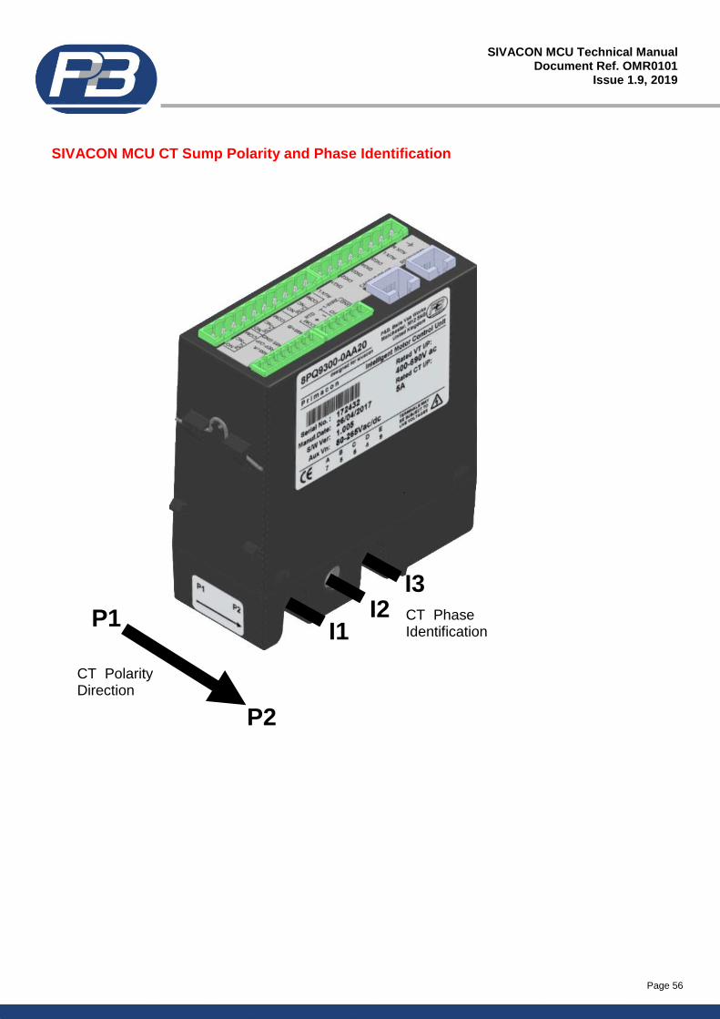
Page 56
SIVACON MCU Technical Manual Document Ref. OMR0101
Issue 1.9, 2019
SIVACON MCU CT Sump Polarity and Phase Identification
I1 I2
I3
P2
P1
CT_Polarity Direction
CT_Phase Identification
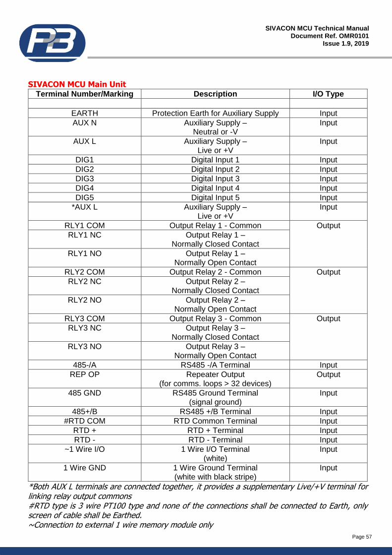
Page 57
SIVACON MCU Technical Manual Document Ref. OMR0101
Issue 1.9, 2019
SIVACON MCU Main Unit
Terminal Number/Marking Description I/O Type
EARTH Protection Earth for Auxiliary Supply Input AUX N Auxiliary Supply –
Neutral or -V Input
AUX L Auxiliary Supply – Live or +V
Input
DIG1 Digital Input 1 Input DIG2 Digital Input 2 Input DIG3 Digital Input 3 Input DIG4 Digital Input 4 Input DIG5 Digital Input 5 Input
*AUX L Auxiliary Supply – Live or +V
Input
RLY1 COM Output Relay 1 - Common Output RLY1 NC Output Relay 1 –
Normally Closed Contact
RLY1 NO Output Relay 1 – Normally Open Contact
RLY2 COM Output Relay 2 - Common Output RLY2 NC Output Relay 2 –
Normally Closed Contact
RLY2 NO Output Relay 2 – Normally Open Contact
RLY3 COM Output Relay 3 - Common Output RLY3 NC Output Relay 3 –
Normally Closed Contact
RLY3 NO Output Relay 3 – Normally Open Contact
485-/A RS485 -/A Terminal Input
REP OP Repeater Output (for comms. loops > 32 devices)
Output
485 GND RS485 Ground Terminal (signal ground)
Input
485+/B RS485 +/B Terminal Input
#RTD COM RTD Common Terminal Input
RTD + RTD + Terminal Input
RTD - RTD - Terminal Input
~1 Wire I/O 1 Wire I/O Terminal (white)
Input
1 Wire GND 1 Wire Ground Terminal (white with black stripe)
Input
*Both AUX L terminals are connected together, it provides a supplementary Live/+V terminal for linking relay output commons #RTD type is 3 wire PT100 type and none of the connections shall be connected to Earth, only screen of cable shall be Earthed. ~Connection to external 1 wire memory module only
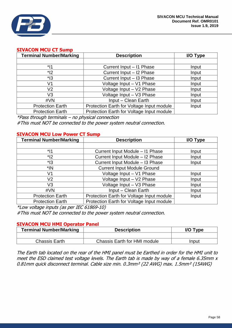
Page 58
SIVACON MCU Technical Manual Document Ref. OMR0101
Issue 1.9, 2019
SIVACON MCU CT Sump
Terminal Number/Marking Description I/O Type
*I1 Current Input – I1 Phase Input *I2 Current Input – I2 Phase Input *I3 Current Input – I3 Phase Input V1 Voltage Input – V1 Phase Input V2 Voltage Input – V2 Phase Input V3 Voltage Input – V3 Phase Input
#VN Input – Clean Earth Input
Protection Earth Protection Earth for Voltage Input module Input
Protection Earth Protection Earth for Voltage Input module
*Pass through terminals – no physical connection #This must NOT be connected to the power system neutral connection. SIVACON MCU Low Power CT Sump
Terminal Number/Marking Description I/O Type
*I1 Current Input Module – I1 Phase Input *I2 Current Input Module – I2 Phase Input *I3 Current Input Module – I3 Phase Input *IN Current Input Module Ground
V1 Voltage Input – V1 Phase Input V2 Voltage Input – V2 Phase Input V3 Voltage Input – V3 Phase Input
#VN Input – Clean Earth Input
Protection Earth Protection Earth for Voltage Input module Input
Protection Earth Protection Earth for Voltage Input module
*Low voltage inputs (as per IEC 61869-10) #This must NOT be connected to the power system neutral connection. SIVACON MCU HMI Operator Panel
Terminal Number/Marking Description I/O Type
Chassis Earth Chassis Earth for HMI module Input
The Earth tab located on the rear of the HMI panel must be Earthed in order for the HMI unit to meet the ESD claimed test voltage levels. The Earth tab is made by way of a female 6.35mm x 0.81mm quick disconnect terminal. Cable size min. 0.3mm² (22 AWG) max. 1.5mm² (15AWG)
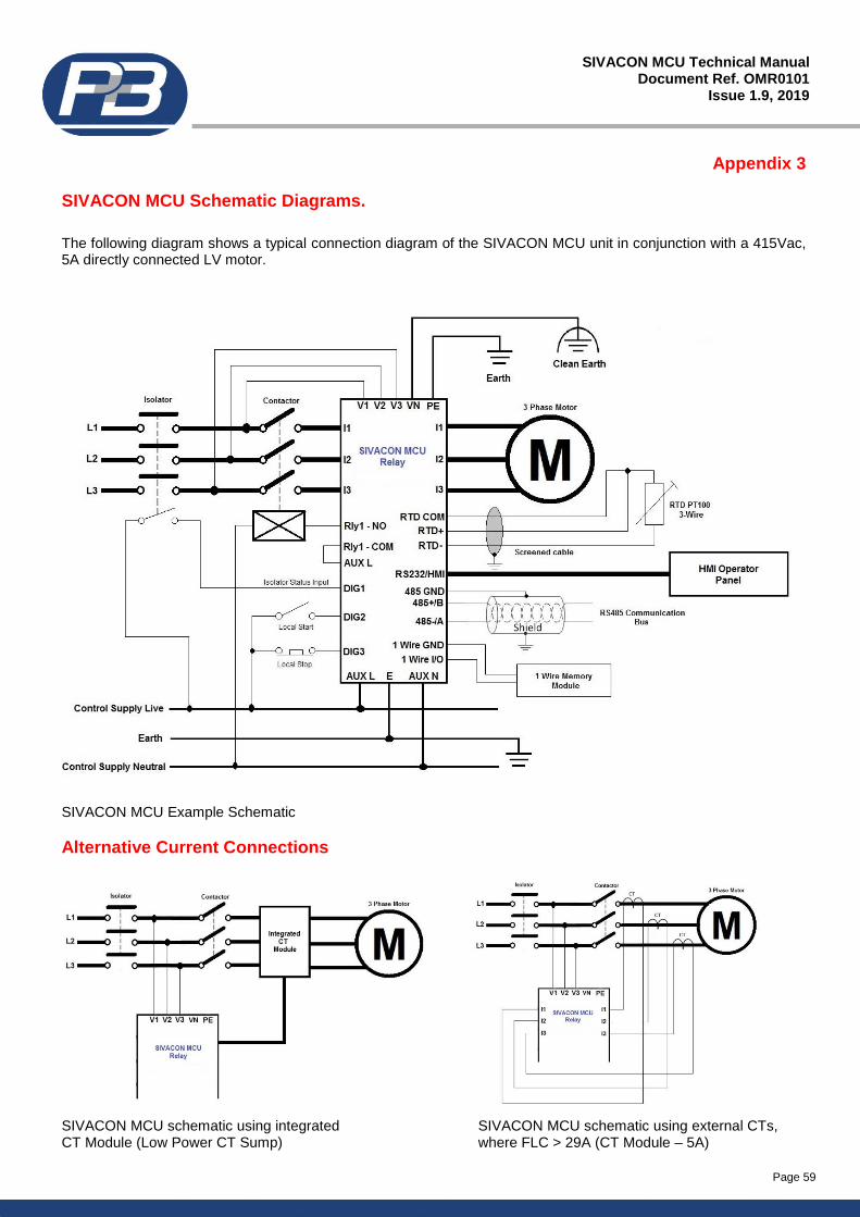
Page 59
SIVACON MCU Technical Manual Document Ref. OMR0101
Issue 1.9, 2019
Appendix 3
SIVACON MCU Schematic Diagrams.
The following diagram shows a typical connection diagram of the SIVACON MCU unit in conjunction with a 415Vac, 5A directly connected LV motor.
SIVACON MCU Example Schematic
Alternative Current Connections
SIVACON MCU schematic using integrated SIVACON MCU schematic using external CTs, CT Module (Low Power CT Sump) where FLC > 29A (CT Module – 5A)
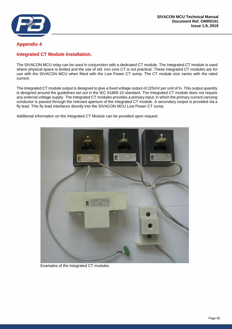
Page 60
SIVACON MCU Technical Manual Document Ref. OMR0101
Issue 1.9, 2019
Appendix 4
Integrated CT Module Installation.
The SIVACON MCU relay can be used in conjunction with a dedicated CT module. The Integrated CT module is used where physical space is limited and the use of std. iron core CT is not practical. These integrated CT modules are for use with the SIVACON MCU when fitted with the Low Power CT sump. The CT module size varies with the rated current.
The integrated CT module output is designed to give a fixed voltage output of 225mV per unit of In. This output quantity is designed around the guidelines set out in the IEC 61869-10 standard. The Integrated CT module does not require any external voltage supply. The Integrated CT modules provides a primary input, in which the primary current carrying conductor is passed through the relevant aperture of the integrated CT module. A secondary output is provided via a fly lead. This fly lead interfaces directly into the SIVACON MCU Low Power CT sump.
Additional information on the Integrated CT Module can be provided upon request.
Examples of the Integrated CT modules
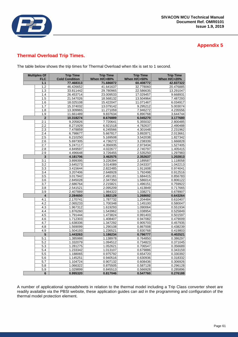
Page 61
SIVACON MCU Technical Manual Document Ref. OMR0101
Issue 1.9, 2019
Appendix 5
Thermal Overload Trip Times.
The table below shows the trip times for Thermal Overload when t6x is set to 1 second.
Multiples Of FLC
Trip Time Cold Condition
Trip Time When H/C=80%
Trip Time When H/C=50%
Trip Time When H/C=20%
1.1 77.468313 71.686872 60.408772 42.837322
1.2 46.426652 41.641637 32.778060 20.476885
1.3 33.811442 29.780965 22.586635 13.291047
1.4 26.453714 23.009533 17.029457 9.668931
1.5 21.547026 18.568132 13.504964 7.487293
1.6 18.025108 15.422047 11.071467 6.034917
1.7 15.374032 13.079142 9.295212 5.003074
1.8 13.309965 11.271059 7.946272 4.235556
1.9 11.661489 9.837634 6.890768 3.644744
2 10.318274 8.676889 6.045270 3.177680
2.1 9.205826 7.720641 5.355032 2.800485
2.2 8.271929 6.921518 4.782637 2.490488
2.3 7.478859 6.245566 4.301648 2.231962
2.4 6.798677 5.667817 3.892871 2.013661
2.5 6.210250 5.169508 3.542038 1.827342
2.6 5.697305 4.736272 3.238339 1.666828
2.7 5.247117 4.356935 2.973434 1.527405
2.8 4.849597 4.022677 2.740797 1.405415
2.9 4.496648 3.726455 2.535250 1.297983
3 4.181706 3.462575 2.352637 1.202813
3.1 3.899395 3.226394 2.189587 1.118058
3.2 3.645273 3.014089 2.043337 1.042213
3.3 3.415644 2.822485 1.911608 0.974041
3.4 3.207406 2.648928 1.792498 0.912516
3.5 3.017942 2.491181 1.684415 0.856783
3.6 2.845028 2.347350 1.586014 0.806122
3.7 2.686764 2.215821 1.496151 0.759922
3.8 2.541521 2.095209 1.413849 0.717665
3.9 2.407889 1.984322 1.338271 0.678907
4 2.284650 1.882129 1.268692 0.643264
4.1 2.170741 1.787732 1.204484 0.610407
4.2 2.065233 1.700348 1.145100 0.580047
4.3 1.967312 1.619293 1.090064 0.551934
4.4 1.876260 1.543962 1.038954 0.525849
4.5 1.791444 1.473824 0.991403 0.501597
4.6 1.712303 1.408407 0.947082 0.479009
4.7 1.638336 1.347292 0.905703 0.457935
4.8 1.569099 1.290108 0.867008 0.438239
4.9 1.504193 1.236521 0.830768 0.419803
5 1.443263 1.186234 0.796777 0.402521
5.1 1.385988 1.138978 0.764850 0.386297
5.2 1.332079 1.094512 0.734823 0.371045
5.3 1.281275 1.052621 0.706547 0.356689
5.4 1.233342 1.013107 0.679886 0.343159
5.5 1.188065 0.975792 0.654720 0.330392
5.6 1.145251 0.940516 0.630936 0.318332
5.7 1.104724 0.907132 0.608436 0.306926
5.8 1.066322 0.875505 0.587128 0.296128
5.9 1.029899 0.845513 0.566928 0.285896
6 0.995320 0.817046 0.547760 0.276188
A number of applicational spreadsheets in relation to the thermal model including a Trip Class converter sheet are readily available via the PBSI website, these application guides can aid in the programming and configuration of the thermal model protection element.
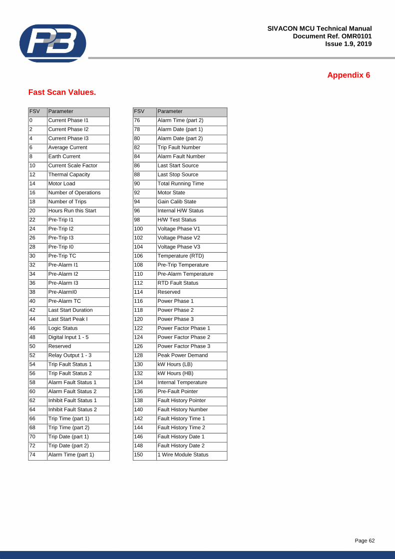
Page 62
SIVACON MCU Technical Manual Document Ref. OMR0101
Issue 1.9, 2019
Appendix 6
Fast Scan Values.
FSV Parameter FSV Parameter
0 Current Phase I1 76 Alarm Time (part 2)
2 Current Phase I2 78 Alarm Date (part 1)
4 Current Phase I3 80 Alarm Date (part 2)
6 Average Current 82 Trip Fault Number
8 Earth Current 84 Alarm Fault Number
10 Current Scale Factor 86 Last Start Source
12 Thermal Capacity 88 Last Stop Source
14 Motor Load 90 Total Running Time
16 Number of Operations 92 Motor State
18 Number of Trips 94 Gain Calib State
20 Hours Run this Start 96 Internal H/W Status
22 Pre-Trip I1 98 H/W Test Status
24 Pre-Trip I2 100 Voltage Phase V1
26 Pre-Trip I3 102 Voltage Phase V2
28 Pre-Trip I0 104 Voltage Phase V3
30 Pre-Trip TC 106 Temperature (RTD)
32 Pre-Alarm I1 108 Pre-Trip Temperature
34 Pre-Alarm I2 110 Pre-Alarm Temperature
36 Pre-Alarm I3 112 RTD Fault Status
38 Pre-AlarmI0 114 Reserved
40 Pre-Alarm TC 116 Power Phase 1
42 Last Start Duration 118 Power Phase 2
44 Last Start Peak I 120 Power Phase 3
46 Logic Status 122 Power Factor Phase 1
48 Digital Input 1 - 5 124 Power Factor Phase 2
50 Reserved 126 Power Factor Phase 3
52 Relay Output 1 - 3 128 Peak Power Demand
54 Trip Fault Status 1 130 kW Hours (LB)
56 Trip Fault Status 2 132 kW Hours (HB)
58 Alarm Fault Status 1 134 Internal Temperature
60 Alarm Fault Status 2 136 Pre-Fault Pointer
62 Inhibit Fault Status 1 138 Fault History Pointer
64 Inhibit Fault Status 2 140 Fault History Number
66 Trip Time (part 1) 142 Fault History Time 1
68 Trip Time (part 2) 144 Fault History Time 2
70 Trip Date (part 1) 146 Fault History Date 1
72 Trip Date (part 2) 148 Fault History Date 2
74 Alarm Time (part 1) 150 1 Wire Module Status
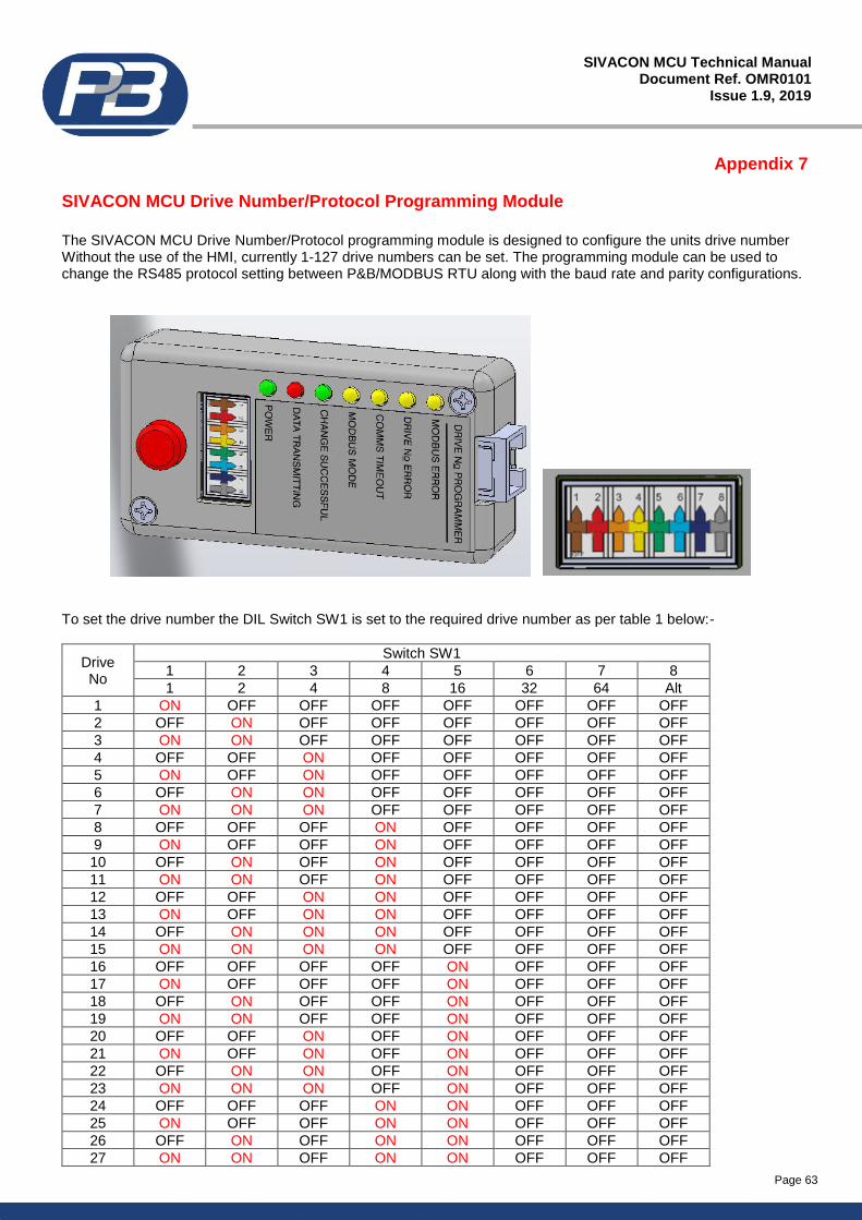
Page 63
SIVACON MCU Technical Manual Document Ref. OMR0101
Issue 1.9, 2019
Appendix 7
SIVACON MCU Drive Number/Protocol Programming Module
The SIVACON MCU Drive Number/Protocol programming module is designed to configure the units drive number Without the use of the HMI, currently 1-127 drive numbers can be set. The programming module can be used to change the RS485 protocol setting between P&B/MODBUS RTU along with the baud rate and parity configurations.
To set the drive number the DIL Switch SW1 is set to the required drive number as per table 1 below:-
Drive No
Switch SW1
1 2 3 4 5 6 7 8
1 2 4 8 16 32 64 Alt
1 ON OFF OFF OFF OFF OFF OFF OFF
2 OFF ON OFF OFF OFF OFF OFF OFF
3 ON ON OFF OFF OFF OFF OFF OFF
4 OFF OFF ON OFF OFF OFF OFF OFF
5 ON OFF ON OFF OFF OFF OFF OFF
6 OFF ON ON OFF OFF OFF OFF OFF
7 ON ON ON OFF OFF OFF OFF OFF
8 OFF OFF OFF ON OFF OFF OFF OFF
9 ON OFF OFF ON OFF OFF OFF OFF
10 OFF ON OFF ON OFF OFF OFF OFF
11 ON ON OFF ON OFF OFF OFF OFF
12 OFF OFF ON ON OFF OFF OFF OFF
13 ON OFF ON ON OFF OFF OFF OFF
14 OFF ON ON ON OFF OFF OFF OFF
15 ON ON ON ON OFF OFF OFF OFF
16 OFF OFF OFF OFF ON OFF OFF OFF
17 ON OFF OFF OFF ON OFF OFF OFF
18 OFF ON OFF OFF ON OFF OFF OFF
19 ON ON OFF OFF ON OFF OFF OFF
20 OFF OFF ON OFF ON OFF OFF OFF
21 ON OFF ON OFF ON OFF OFF OFF
22 OFF ON ON OFF ON OFF OFF OFF
23 ON ON ON OFF ON OFF OFF OFF
24 OFF OFF OFF ON ON OFF OFF OFF
25 ON OFF OFF ON ON OFF OFF OFF
26 OFF ON OFF ON ON OFF OFF OFF
27 ON ON OFF ON ON OFF OFF OFF
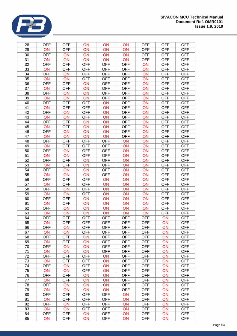
Page 64
SIVACON MCU Technical Manual Document Ref. OMR0101
Issue 1.9, 2019
28 OFF OFF ON ON ON OFF OFF OFF
29 ON OFF ON ON ON OFF OFF OFF
30 OFF ON ON ON ON OFF OFF OFF
31 ON ON ON ON ON OFF OFF OFF
32 OFF OFF OFF OFF OFF ON OFF OFF
33 ON OFF OFF OFF OFF ON OFF OFF
34 OFF ON OFF OFF OFF ON OFF OFF
35 ON ON OFF OFF OFF ON OFF OFF
36 OFF OFF ON OFF OFF ON OFF OFF
37 ON OFF ON OFF OFF ON OFF OFF
38 OFF ON ON OFF OFF ON OFF OFF
39 ON ON ON OFF OFF ON OFF OFF
40 OFF OFF OFF ON OFF ON OFF OFF
41 ON OFF OFF ON OFF ON OFF OFF
42 OFF ON OFF ON OFF ON OFF OFF
43 ON ON OFF ON OFF ON OFF OFF
44 OFF OFF ON ON OFF ON OFF OFF
45 ON OFF ON ON OFF ON OFF OFF
46 OFF ON ON ON OFF ON OFF OFF
47 ON ON ON ON OFF ON OFF OFF
48 OFF OFF OFF OFF ON ON OFF OFF
49 ON OFF OFF OFF ON ON OFF OFF
50 OFF ON OFF OFF ON ON OFF OFF
51 ON ON OFF OFF ON ON OFF OFF
52 OFF OFF ON OFF ON ON OFF OFF
53 ON OFF ON OFF ON ON OFF OFF
54 OFF ON ON OFF ON ON OFF OFF
55 ON ON ON OFF ON ON OFF OFF
56 OFF OFF OFF ON ON ON OFF OFF
57 ON OFF OFF ON ON ON OFF OFF
58 OFF ON OFF ON ON ON OFF OFF
59 ON ON OFF ON ON ON OFF OFF
60 OFF OFF ON ON ON ON OFF OFF
61 ON OFF ON ON ON ON OFF OFF
62 OFF ON ON ON ON ON OFF OFF
63 ON ON ON ON ON ON OFF OFF
64 OFF OFF OFF OFF OFF OFF ON OFF
65 ON OFF OFF OFF OFF OFF ON OFF
66 OFF ON OFF OFF OFF OFF ON OFF
67 ON ON OFF OFF OFF OFF ON OFF
68 OFF OFF ON OFF OFF OFF ON OFF
69 ON OFF ON OFF OFF OFF ON OFF
70 OFF ON ON OFF OFF OFF ON OFF
71 ON ON ON OFF OFF OFF ON OFF
72 OFF OFF OFF ON OFF OFF ON OFF
73 ON OFF OFF ON OFF OFF ON OFF
74 OFF ON OFF ON OFF OFF ON OFF
75 ON ON OFF ON OFF OFF ON OFF
76 OFF OFF ON ON OFF OFF ON OFF
77 ON OFF ON ON OFF OFF ON OFF
78 OFF ON ON ON OFF OFF ON OFF
79 ON ON ON ON OFF OFF ON OFF
80 OFF OFF OFF OFF ON OFF ON OFF
81 ON OFF OFF OFF ON OFF ON OFF
82 OFF ON OFF OFF ON OFF ON OFF
83 ON ON OFF OFF ON OFF ON OFF
84 OFF OFF ON OFF ON OFF ON OFF
85 ON OFF ON OFF ON OFF ON OFF
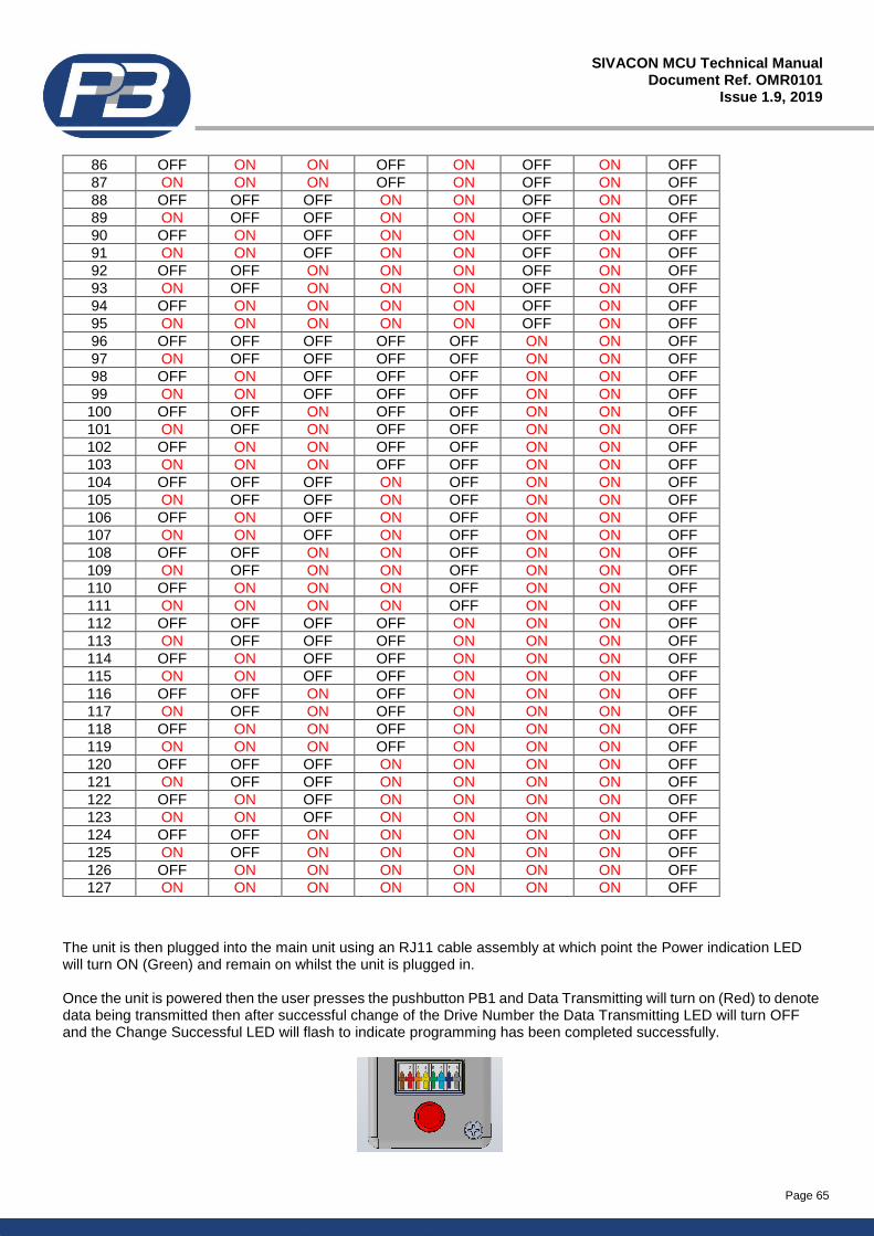
Page 65
SIVACON MCU Technical Manual Document Ref. OMR0101
Issue 1.9, 2019
86 OFF ON ON OFF ON OFF ON OFF
87 ON ON ON OFF ON OFF ON OFF
88 OFF OFF OFF ON ON OFF ON OFF
89 ON OFF OFF ON ON OFF ON OFF
90 OFF ON OFF ON ON OFF ON OFF
91 ON ON OFF ON ON OFF ON OFF
92 OFF OFF ON ON ON OFF ON OFF
93 ON OFF ON ON ON OFF ON OFF
94 OFF ON ON ON ON OFF ON OFF
95 ON ON ON ON ON OFF ON OFF
96 OFF OFF OFF OFF OFF ON ON OFF
97 ON OFF OFF OFF OFF ON ON OFF
98 OFF ON OFF OFF OFF ON ON OFF
99 ON ON OFF OFF OFF ON ON OFF
100 OFF OFF ON OFF OFF ON ON OFF
101 ON OFF ON OFF OFF ON ON OFF
102 OFF ON ON OFF OFF ON ON OFF
103 ON ON ON OFF OFF ON ON OFF
104 OFF OFF OFF ON OFF ON ON OFF
105 ON OFF OFF ON OFF ON ON OFF
106 OFF ON OFF ON OFF ON ON OFF
107 ON ON OFF ON OFF ON ON OFF
108 OFF OFF ON ON OFF ON ON OFF
109 ON OFF ON ON OFF ON ON OFF
110 OFF ON ON ON OFF ON ON OFF
111 ON ON ON ON OFF ON ON OFF
112 OFF OFF OFF OFF ON ON ON OFF
113 ON OFF OFF OFF ON ON ON OFF
114 OFF ON OFF OFF ON ON ON OFF
115 ON ON OFF OFF ON ON ON OFF
116 OFF OFF ON OFF ON ON ON OFF
117 ON OFF ON OFF ON ON ON OFF
118 OFF ON ON OFF ON ON ON OFF
119 ON ON ON OFF ON ON ON OFF
120 OFF OFF OFF ON ON ON ON OFF
121 ON OFF OFF ON ON ON ON OFF
122 OFF ON OFF ON ON ON ON OFF
123 ON ON OFF ON ON ON ON OFF
124 OFF OFF ON ON ON ON ON OFF
125 ON OFF ON ON ON ON ON OFF
126 OFF ON ON ON ON ON ON OFF
127 ON ON ON ON ON ON ON OFF
The unit is then plugged into the main unit using an RJ11 cable assembly at which point the Power indication LED will turn ON (Green) and remain on whilst the unit is plugged in. Once the unit is powered then the user presses the pushbutton PB1 and Data Transmitting will turn on (Red) to denote data being transmitted then after successful change of the Drive Number the Data Transmitting LED will turn OFF and the Change Successful LED will flash to indicate programming has been completed successfully.
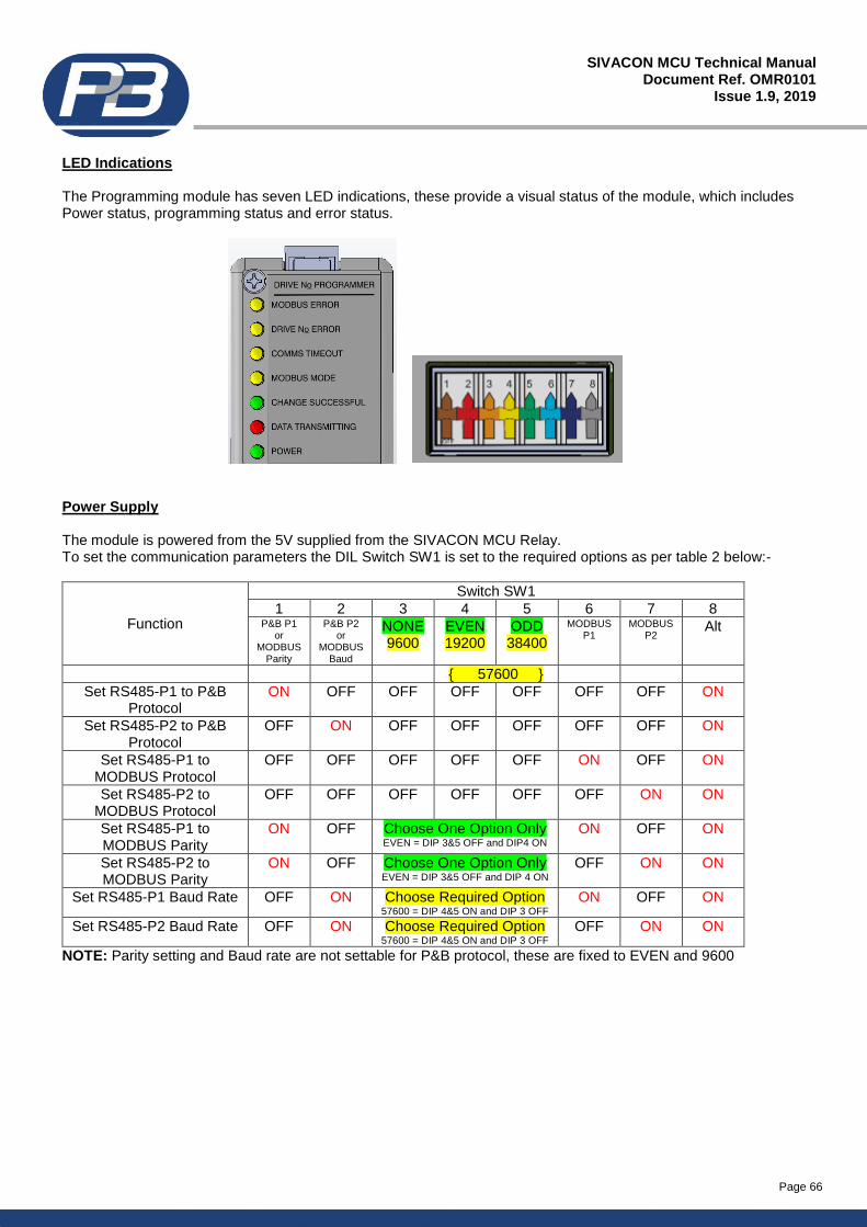
Page 66
SIVACON MCU Technical Manual Document Ref. OMR0101
Issue 1.9, 2019
LED Indications The Programming module has seven LED indications, these provide a visual status of the module, which includes Power status, programming status and error status.
Power Supply The module is powered from the 5V supplied from the SIVACON MCU Relay. To set the communication parameters the DIL Switch SW1 is set to the required options as per table 2 below:-
Function
Switch SW1
1 2 3 4 5 6 7 8 P&B P1
or MODBUS
Parity
P&B P2 or
MODBUS Baud
NONE 9600
EVEN 19200
ODD 38400
MODBUS P1
MODBUS P2
Alt
{ 57600 }
Set RS485-P1 to P&B Protocol
ON OFF OFF OFF OFF OFF OFF ON
Set RS485-P2 to P&B Protocol
OFF ON OFF OFF OFF OFF OFF ON
Set RS485-P1 to MODBUS Protocol
OFF OFF OFF OFF OFF ON OFF ON
Set RS485-P2 to MODBUS Protocol
OFF OFF OFF OFF OFF OFF ON ON
Set RS485-P1 to MODBUS Parity
ON OFF Choose One Option Only EVEN = DIP 3&5 OFF and DIP4 ON
ON OFF ON
Set RS485-P2 to MODBUS Parity
ON OFF Choose One Option Only EVEN = DIP 3&5 OFF and DIP 4 ON
OFF ON ON
Set RS485-P1 Baud Rate OFF ON Choose Required Option 57600 = DIP 4&5 ON and DIP 3 OFF
ON OFF ON
Set RS485-P2 Baud Rate OFF ON Choose Required Option 57600 = DIP 4&5 ON and DIP 3 OFF
OFF ON ON
NOTE: Parity setting and Baud rate are not settable for P&B protocol, these are fixed to EVEN and 9600
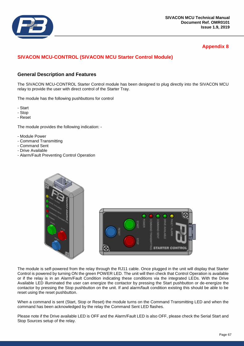
Page 67
SIVACON MCU Technical Manual Document Ref. OMR0101
Issue 1.9, 2019
Appendix 8
SIVACON MCU-CONTROL (SIVACON MCU Starter Control Module)
General Description and Features The SIVACON MCU-CONTROL Starter Control module has been designed to plug directly into the SIVACON MCU relay to provide the user with direct control of the Starter Tray. The module has the following pushbuttons for control - Start - Stop - Reset The module provides the following indication: - - Module Power - Command Transmitting - Command Sent - Drive Available - Alarm/Fault Preventing Control Operation
The module is self-powered from the relay through the RJ11 cable. Once plugged in the unit will display that Starter Control is powered by turning ON the green POWER LED. The unit will then check that Control Operation is available or if the relay is in an Alarm/Fault Condition indicating these conditions via the integrated LEDs. With the Drive Available LED illuminated the user can energize the contactor by pressing the Start pushbutton or de-energize the contactor by pressing the Stop pushbutton on the unit. If and alarm/fault condition existing this should be able to be reset using the reset pushbutton. When a command is sent (Start, Stop or Reset) the module turns on the Command Transmitting LED and when the command has been acknowledged by the relay the Command Sent LED flashes. Please note if the Drive available LED is OFF and the Alarm/Fault LED is also OFF, please check the Serial Start and Stop Sources setup of the relay.
Page 68
SIVACON MCU Technical Manual Document Ref. OMR0101
Issue 1.9, 2019
Appendix 9
Installation and Maintenance
This appendix describes the Safety and Commissioning information required for when installing the SIVACON MCU product. This manual is aimed at specialist personnel who are responsible for the installation, commissioning and maintenance of motor protection relays. It is imperative that you observe the information contained within this appendix as it supports the application of the product. This document must be used in conjunction with other supporting documents to achieve correct installation, commissioning and operation. Specifically, the SIVACON MCU Technical Manual (Issue 1.9) and applicable certificates for the particular product should be consulted, all of which are available on the PBSI GROUP website (http://www.pbsigroup.com).
All installation, commissioning and maintenance work is to be carried out by responsible, qualified personnel only. Unprofessional behaviour can cause serious damage to persons and goods. Due to our continuing efforts in product development we reserve the right to make design changes.
Application and Function The SIVACON MCU protection relay is a 3 phase AC motor protection relay, which is designed to offer electrical protection for 3 phase AC motors. Each SIVACON MCU relay will be connected to a single 3 phase AC motor only. The SIVACON MCU product is designed to offer protection for motors with a Full Load Currents (FLC) in the range of 0.5A to 2000A. The SIVACON MCU monitors the 3 phase motor currents along with the zero sequence current (Ground/Earth Fault). The SIVACON MCU provides monitoring for three phase voltage measurement directly connected up to 690Vac. In additional to the analogue monitoring, the SIVACON MCU provides 5 x Digital Inputs, 3 x Relay Outputs, an Industrial RS485 Communication Bus and an RTD Temperature Input. The SIVACON MCU can be programmed to provide control for a number of motor applications, these include; Direct-On-Line, Direct-On-Line Reversing, Star-Delta, Two-Speed, Circuit Breaker and Variable Speed. The SIVACON MCU provides a number of input and output signals, which are hardwired to provide protection, control and monitoring functionality Each of the input and output signals are programmable dependent on the motor application configuration. The SIVACON MCU is equipped with a high speed industrial RS485 communication bus, this provides remote access to the unit via a Programmable Logic Controller (PLC) or a Distributed Control System (DCS) for control and monitoring purposes. The Communication Bus provides full access to the measured, fault, statistical and settings data.
System Configuration and Product Selection Implications The SIVACON MCU can support a number of different starter types and application configurations. These include the power system and connection of the protected device to the power system via the SIVACON MCU product. The details provided below show the system configuration and specifies the detailed interfaces to the safety related and non-safety related system components along with the implications for the range of variants available within the product selection. The information provided in this section does not aim to show all details of the relay hardware/software internal configuration, but is intended to support understanding for the application. The operating conditions of the SIVACON MCU Relay are as follows: -
Operating Temperature -20 to +80°C
Supply Voltage Range Standard Version: 80 to 265Vac/dc Low Voltage Version (LV): 24/48Vac or 18 to 72Vdc
Maximum Vibration Values Class I as per IEC 60255-21-1
Maximum Shock Values Class I as per IEC 60255-21-2
Page 69
SIVACON MCU Technical Manual Document Ref. OMR0101
Issue 1.9, 2019
Power System Connection The SIVACON MCU protection relay can be directly connected to a low voltage power system up to 690Vac and with a motor FLC of up to 29A without the need for any external measurement transducers. Where the Power System supply is greater than 690Vac or the motor FLC is greater than 29A, then external measurement transducers will be required, such as Voltage and Current Transformers The SIVACON MCU protection relay is designed for use in normal industrial electromagnetic environment but, to support, good practice, the product should be installed without being subjected to undue conducted or radiated interference. The SIVACON MCU technical manual details the applicable standards. The SIVACON MCU protection relay is designed to operate over the temperature range -20°C to +80°C and at up to 95% non-condensing relative humidity. The product is intended to be installed in a normal industrial environment without excessive vibration, as specified in the technical manual. Continued reliable operation will be assured if the exposure to temperature, humidity and vibration are within the values provided in this document.
Installation Reference must be made to the relevant sections within Technical Manual for the SIVACON MCU, which contain basic guides for the installation of the interface equipment to meet the requirements needed to adequately protect the connected 3 phase motor. In many Countries there are specific codes of practice, together with industry guidelines, which also must be adhered to. The SIVACON MCU protection relay is supplied with factory default settings pre-loaded. The default setting values are documented in section 9 of the SIVACON MCU technical manual. Under no circumstances should the SIVACON MCU relay be placed into service using these default settings. A suitable protection study shall be undertaken for each electrical circuit to be protected, the settings produced from this study will then form the basis for configuration of the parameters to be set within the SIVACON MCU protection relay. Care should be taken when routing the fixed wiring for the SIVACON MCU product within the switchgear panel. The SIVACON MCU unit has several different distinct interface ports, such as digital communication, digital inputs, analogue temperature measurement and analogue current and voltage inputs taken from the power system. Identification of these different input/output ports should be made during any installation assessment and where required adequate separation of cables and routing should be made to avoid any potential coupling of stray capacitive or inductive signals onto adjacent cables and or from other sources from within the switchgear panel. The SIVACON MCU has been designed to operate in accordance with the relevant IEC standards, but, to support, good practice, the product should be installed without being subjected to undue conducted/radiated interference or electrical transient/surges. The SIVACON MCU technical manual details the applicable standards. The SIVACON MCU front panel, provides an IP rating of IP54, the IP rating on the main unit offers limited IP rating and as such is classified as IP30. The SIVACON MCU main unit is design to be DIN rail mounted, therefore to guard against the effects of dust and water the SIVACON MCU should be mounted in an enclosure providing at least IP30 protection degree, or the location of mounting should provide equivalent protection such as inside a switchgear panel or equipment cabinet. In applications where the environment has a high humidity, the SIVACON MCU should be specified to include conformal coating, this provides an additional level of protection to the internal circuit boards from airborne contamination. Conformal coating must be specified at the point of ordering; this cannot be applied retrospectively to the relay.
Page 70
SIVACON MCU Technical Manual Document Ref. OMR0101
Issue 1.9, 2019
Maintenance The maintenance of this product requires expertise in the design and programming of protection and control systems. Only persons with such expertise should be allowed to program, install and maintain and apply this product. Follow all local and national safety codes and standards. Failure to follow these instructions can result in death, serious injury or equipment damage. Yearly periodic audits of the installation maybe required by the various codes of practice. If a SIVACON MCU protection relay is found to be faulty during commissioning or during the normal lifetime of the product, then such failures should be reported to PBSI GROUP LTD. When appropriate, a Return Request (RR) will be notified to enable the return of the unit to the factory for analysis. If the unit is within the warranty period then the unit will be repaired or replaced free of charge. Products outside of the warranty period will be subject to charges. Consideration should be made of the normal lifetime for a device of this type which would be in the region of 5 – 15 years, dependent on ambient temperature in which the equipment is operating. Product lifetime and product testing intervals should be determined based on the environmental conditions and the product demand. It is recommended that all SIVACON MCU relays are powered up at least once per year to avoid deterioration of electrolytic capacitors within the product.
Conditions of Safe Use The following conditions apply to the installation, operation and maintenance of the assessed equipment. Failure to observe these conditions may compromise the safety integrity of the assessed equipment.
1) The user shall comply with the requirements given in the manufacturer’s documentation in regard to all relevant safety aspects, such as the application of use, installation, operation, maintenance, environmental conditions and repair.
2) Selection of this equipment for use in safety applications, configuration, overall validation, maintenance and repair shall only be carried out by trained, competent personnel, observing all the manufacturer’s conditions and recommendations in the technical manual.
3) All information associated with any field failures of this product should be reported to PBSI GROUP Limited. 4) The SIVACON MCU protection relay shall only be installed in a non-hazardous area. The SIVACON MCU
shall only be connected to secure plant communication networks. It must require necessary authorisation to avoid unauthorised operation.
5) Password Protection within the SIVACON MCU relay shall be enabled where possible to avoid unauthorised operation or modification of the devices settings. Obvious passwords such as 11111, AAAAA, 12345 etc. shall be avoided.
6) In collaboration with the manufacturer the user/installer shall ensure that the construction of the final installation is safe and the selection of equipment is acceptable.
7) Change request – should the user or integrator request a change to the product software, then this must be provided to PBSI GROUP LTD either in writing or by email ([email protected]). PBSI will review any requests for change through the change control process and will inform the user or integrator on the decision to accept or deny the request based following an impact assessment.
Technical Support Contact Details
P&B Protection Relays Email: [email protected] Belle Vue Works, Website: http://www.pbsigroup.com Boundary Street, Manchester Agents and Overseas Contact Details M12 5NG http://www.pbsigroup.com/contact-us/ Tel: +44 (0)161 230 6363 Fax: +44 (0)161 230 6464
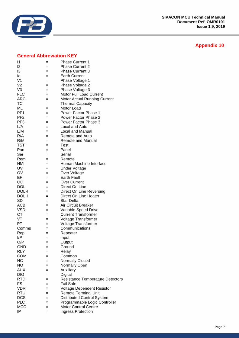
Page 71
SIVACON MCU Technical Manual Document Ref. OMR0101
Issue 1.9, 2019
Appendix 10
General Abbreviation KEY
I1 = Phase Current 1 I2 = Phase Current 2 I3 = Phase Current 3 Io = Earth Current V1 = Phase Voltage 1 V2 = Phase Voltage 2 V3 = Phase Voltage 3 FLC = Motor Full Load Current ARC = Motor Actual Running Current TC = Thermal Capacity ML = Motor Load PF1 = Power Factor Phase 1 PF2 = Power Factor Phase 2 PF3 = Power Factor Phase 3 L/A = Local and Auto L/M = Local and Manual R/A = Remote and Auto R/M = Remote and Manual TST = Test Pan = Panel Ser = Serial Rem = Remote HMI = Human Machine Interface UV = Under Voltage OV = Over Voltage EF = Earth Fault OC = Over Current DOL = Direct On Line DOLR = Direct On Line Reversing DOLH = Direct On Line Heater SD = Star Delta ACB = Air Circuit Breaker VSD = Variable Speed Drive CT = Current Transformer VT = Voltage Transformer PT = Voltage Transformer Comms = Communications Rep = Repeater I/P = Input O/P = Output GND = Ground RLY = Relay COM = Common NC = Normally Closed NO = Normally Open AUX = Auxiliary DIG = Digital RTD = Resistance Temperature Detectors FS = Fail Safe VDR = Voltage Dependent Resistor RTU = Remote Terminal Unit DCS = Distributed Control System PLC = Programmable Logic Controller MCC = Motor Control Centre IP = Ingress Protection
Page 72
SIVACON MCU Technical Manual Document Ref. OMR0101
Issue 1.9, 2019
Appendix 11
Handling Guidelines.
Installation. Protection relaying equipment should be installed, commissioned and programmed by professional engineers familiar with such products. P&B cannot be held liable if proper handling is not observed. The relay is programmed to the factory default settings upon shipment and must be programmed correctly to achieve safe and satisfactory protection of the equipment. Changes to the relay hardware and or software may affect the calibration of the unit and its measurement accuracy should be checked prior to reinstating the product in service. If unsure, contact P&B for advice. Disposal. P&B are committed to manufacturing practices which do not result in pollution or cause damage to the environment. If you wish us to dispose of equipment on your behalf we are able to provide such services.
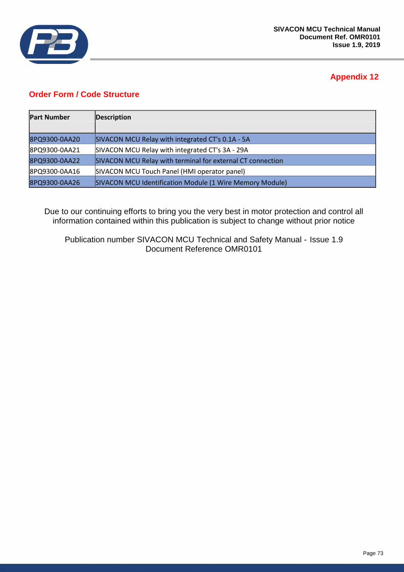
Page 73
SIVACON MCU Technical Manual Document Ref. OMR0101
Issue 1.9, 2019
Appendix 12
Order Form / Code Structure
Part Number Description
8PQ9300-0AA20 SIVACON MCU Relay with integrated CT's 0.1A - 5A
8PQ9300-0AA21 SIVACON MCU Relay with integrated CT's 3A - 29A
8PQ9300-0AA22 SIVACON MCU Relay with terminal for external CT connection
8PQ9300-0AA16 SIVACON MCU Touch Panel (HMI operator panel)
8PQ9300-0AA26 SIVACON MCU Identification Module (1 Wire Memory Module)
Due to our continuing efforts to bring you the very best in motor protection and control all information contained within this publication is subject to change without prior notice
Publication number SIVACON MCU Technical and Safety Manual - Issue 1.9
Document Reference OMR0101