Embed Size (px)
Citation preview
Siemens LV 1 T · 2008
14
SIVACON Power Distribution Boards, Busway and Cubicle Systems
14/2 Introduction
Switchgear14/5 S8 power distribution boards
Components for 8US, 8UC, 4NC Distribution Systems 8US Busbar Systems
14/9 General data
40 mm Busbar Systems14/10 General data14/11 Base assemblies14/12 Supply and connection technologies14/13 Busbar adapters and device holders14/16 Accessories
60 mm Busbar Systems14/17 General data14/18 Base assemblies up to 630 A14/21 Base assemblies up to 1600 A14/22 Supply and connection technologies14/24 Busbar adapters and device holders14/27 Bus-mounting fuse bases14/28 Accessories
Components for 8US, 8UC, 4NC Distribution Systems 8UC Door-Coupling Rotary Operating Mechanisms
14/29 General data14/31 For 3K switch disconnectors14/31 For 3VF and 3VL circuit breakers14/32 Individual parts14/33 Operating mechanisms for fixed
mounting
Components for 8US, 8UC, 4NC Distribution Systems 4NC Current Transformers for Measuring Purposes
14/34 General data14/36 Classes 1 and 3, from 50 A to 1500 A
© Siemens AG 2008
SIVACON Power Distribution Boards, Busway and Cubicle Systems
Introduction
14/2 Siemens LV 1 T · 2008
14
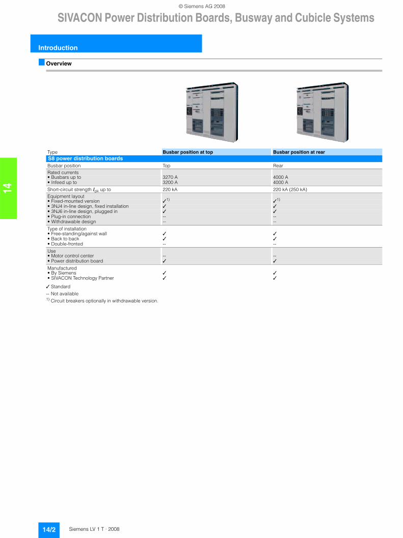
■ Overview
✓ Standard
-- Not available1) Circuit breakers optionally in withdrawable version.
Type Busbar position at top Busbar position at rearS8 power distribution boardsBusbar position Top RearRated currents• Busbars up to 3270 A 4000 A• Infeed up to 3200 A 4000 A
Short-circuit strength Ipk up to 220 kA 220 kA (250 kA)Equipment layout• Fixed-mounted version ✓1) ✓1)
• 3NJ4 in-line design, fixed installation ✓ ✓• 3NJ6 in-line design, plugged in ✓ ✓• Plug-in connection -- --• Withdrawable design -- --
Type of installation• Free-standing/against wall ✓ ✓• Back to back ✓ ✓• Double-fronted -- --
Use• Motor control center -- --• Power distribution board ✓ ✓
Manufactured • By Siemens ✓ ✓• SIVACON Technology Partner ✓ ✓
© Siemens AG 2008
SIVACON Power Distribution Boards, Busway and Cubicle Systems
14/3Siemens LV 1 T · 2008
Introduction
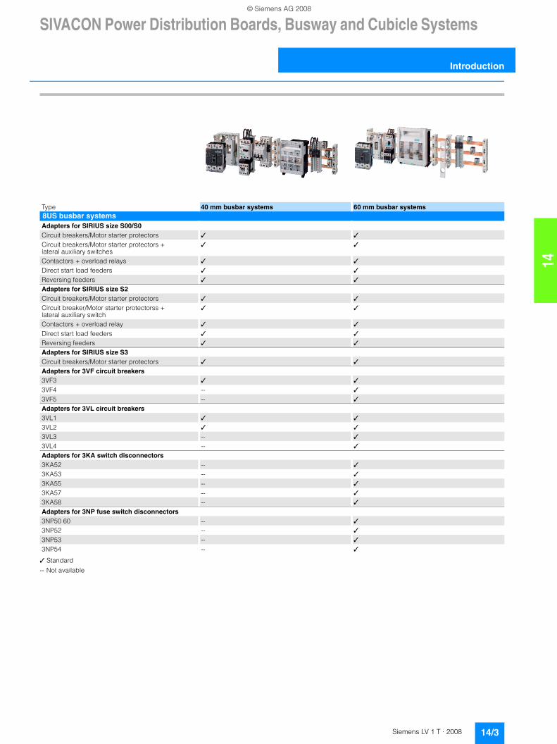
14✓ Standard
-- Not available
Type 40 mm busbar systems 60 mm busbar systems8US busbar systemsAdapters for SIRIUS size S00/S0Circuit breakers/Motor starter protectors ✓ ✓
Circuit breakers/Motor starter protectors + lateral auxiliary switches
✓ ✓
Contactors + overload relays ✓ ✓
Direct start load feeders ✓ ✓
Reversing feeders ✓ ✓
Adapters for SIRIUS size S2Circuit breakers/Motor starter protectors ✓ ✓
Circuit breaker/Motor starter protectorss + lateral auxiliary switch
✓ ✓
Contactors + overload relay ✓ ✓
Direct start load feeders ✓ ✓
Reversing feeders ✓ ✓
Adapters for SIRIUS size S3Circuit breakers/Motor starter protectors ✓ ✓
Adapters for 3VF circuit breakers3VF3 ✓ ✓
3VF4 -- ✓
3VF5 -- ✓
Adapters for 3VL circuit breakers3VL1 ✓ ✓
3VL2 ✓ ✓
3VL3 -- ✓
3VL4 -- ✓
Adapters for 3KA switch disconnectors3KA52 -- ✓
3KA53 -- ✓
3KA55 -- ✓
3KA57 -- ✓
3KA58 -- ✓
Adapters for 3NP fuse switch disconnectors3NP50 60 -- ✓
3NP52 -- ✓
3NP53 -- ✓
3NP54 -- ✓
© Siemens AG 2008
SIVACON Power Distribution Boards, Busway and Cubicle Systems
Introduction
14/4 Siemens LV 1 T · 2008
14
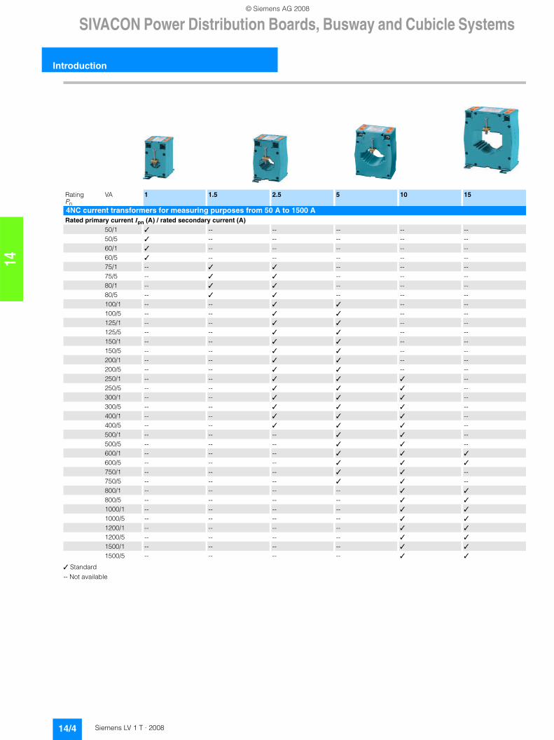
✓ Standard
-- Not available
Rating Pn
VA 1 1.5 2.5 5 10 15
4NC current transformers for measuring purposes from 50 A to 1500 ARated primary current Ipn (A) / rated secondary current (A)
50/1 ✓ -- -- -- -- --50/5 ✓ -- -- -- -- --60/1 ✓ -- -- -- -- --60/5 ✓ -- -- -- -- --75/1 -- ✓ ✓ -- -- --75/5 -- ✓ ✓ -- -- --80/1 -- ✓ ✓ -- -- --80/5 -- ✓ ✓ -- -- --100/1 -- -- ✓ ✓ -- --100/5 -- -- ✓ ✓ -- --125/1 -- -- ✓ ✓ -- --125/5 -- -- ✓ ✓ -- --150/1 -- -- ✓ ✓ -- --150/5 -- -- ✓ ✓ -- --200/1 -- -- ✓ ✓ -- --200/5 -- -- ✓ ✓ -- --250/1 -- -- ✓ ✓ ✓ --250/5 -- -- ✓ ✓ ✓ --300/1 -- -- ✓ ✓ ✓ --300/5 -- -- ✓ ✓ ✓ --400/1 -- -- ✓ ✓ ✓ --400/5 -- -- ✓ ✓ ✓ --500/1 -- -- -- ✓ ✓ --500/5 -- -- -- ✓ ✓ --600/1 -- -- -- ✓ ✓ ✓
600/5 -- -- -- ✓ ✓ ✓
750/1 -- -- -- ✓ ✓ --750/5 -- -- -- ✓ ✓ --800/1 -- -- -- -- ✓ ✓
800/5 -- -- -- -- ✓ ✓
1000/1 -- -- -- -- ✓ ✓
1000/5 -- -- -- -- ✓ ✓
1200/1 -- -- -- -- ✓ ✓
1200/5 -- -- -- -- ✓ ✓
1500/1 -- -- -- -- ✓ ✓
1500/5 -- -- -- -- ✓ ✓
© Siemens AG 2008
Switchgear
14/5Siemens LV 1 T · 2008
S8 power distribution boards
14
■ Overview
SIVACON S8 - the type-tested power distribution board
The SIVACON S8 low-voltage switchboard is a variable, versatile, and type-tested low-voltage controlgear combination (TTA) which is used both in infrastructural supply in administrative and functional buildings as well as industrial and commercial buildings.
The SIVACON S8 consists of standardized and typified components which can be flexibly combined as a cost-effective overall solution.
The SIVACON S8 sets itself apart through its high degree offlexibility and quality with space-saving dimensions and the highest level of personal and machine safety.
We or our authorized contractual partners take care of the following:• Customized configuration• The mechanical and electrical construction• Inspection
Here we use type-tested functional components. We use the documentation prescribed by us as the basis for our authorized contractual partners.
SIVACON S8 can be used as a type-tested power distribution board up to 4000 A.
Standards and specifications
SIVACON S8 is a type-tested low-voltage controlgear combinations (TTA) according to IEC 60439-, EN 60439-1 (VDE 0660 Part 500). SIVACON S8 is designed to be resistant to arcing faults according to IEC 61641, EN 60439 (VDE 0660 Part 500), supplement sheet 2.
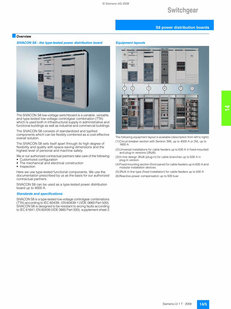
Equipment layouts
The following equipment layout is available (description from left to right):(1)Circuit breaker section with Sentron 3WL up to 4000 A or 3VL up to
1600 A.
(2)Universal installations for cable feeders up to 630 A in fixed-mounted and plug-in versions (3NJ6)
(3) In-line design 3NJ6 (plug-in) for cable branches up to 630 A in plug-in version.
(4)Fixed mounting section (front panel) for cable feeders up to 630 A and modular installation devices.
(5)3NJ4 in-line type (fixed installation) for cable feeders up to 630 A(6)Reactive-power compensation up to 500 kvar
NSF0_00216
© Siemens AG 2008
Switchgear
S8 power distribution boards
14/6 Siemens LV 1 T · 2008
14
■ Design
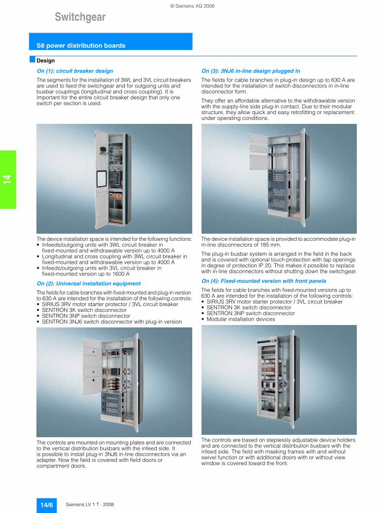
On (1): circuit breaker design
The segments for the installation of 3WL and 3VL circuit breakers are used to feed the switchgear and for outgoing units and busbar couplings (longitudinal and cross coupling). It is important for the entire circuit breaker design that only one switch per section is used.
The device installation space is intended for the following functions:• Infeeds/outgoing units with 3WL circuit breaker in
fixed-mounted and withdrawable version up to 4000 A• Longitudinal and cross coupling with 3WL circuit breaker in
fixed-mounted and withdrawable version up to 4000 A• Infeeds/outgoing units with 3VL circuit breaker in
fixed-mounted version up to 1600 A
On (2): Universal installation equipment
The fields for cable branches with fixed-mounted and plug-in version to 630 A are intended for the installation of the following controls:• SIRIUS 3RV motor starter protector / 3VL circuit breaker• SENTRON 3K switch disconnector• SENTRON 3NP switch disconnector• SENTRON 3NJ6 switch disconnector with plug-in version
The controls are mounted on mounting plates and are connected to the vertical distribution busbars with the infeed side. It is possible to install plug-in 3NJ6 in-line disconnectors via an adapter. Now the field is covered with field doors or compartment doors.
On (3): 3NJ6 in-line design plugged in
The fields for cable branches in plug-in design up to 630 A are intended for the installation of switch disconnectors in in-line disconnector form.
They offer an affordable alternative to the withdrawable version with the supply-line side plug-in contact. Due to their modular structure, they allow quick and easy retrofitting or replacement under operating conditions.
The device installation space is provided to accommodate plug-in in-line disconnectors of 185 mm.
The plug-in busbar system is arranged in the field in the back and is covered with optional touch protection with tap openings in degree of protection IP 20. This makes it possible to replace with in-line disconnectors without shutting down the switchgear.
On (4): Fixed-mounted version with front panels
The fields for cable branches with fixed-mounted versions up to 630 A are intended for the installation of the following controls:• SIRIUS 3RV motor starter protector / 3VL circuit breaker• SENTRON 3K switch disconnector• SENTRON 3NP switch disconnector• Modular installation devices
The controls are based on steplessly adjustable device holders and are connected to the vertical distribution busbars with the infeed side. The field with masking frames with and without swivel function or with additional doors with or without view window is covered toward the front.
© Siemens AG 2008
Switchgear
14/7Siemens LV 1 T · 2008
S8 power distribution boards
14
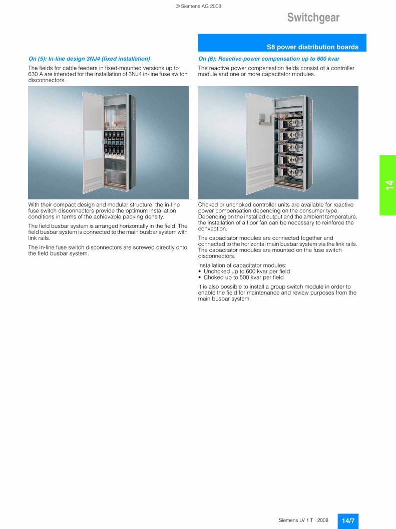
On (5): In-line design 3NJ4 (fixed installation)
The fields for cable feeders in fixed-mounted versions up to 630 A are intended for the installation of 3NJ4 in-line fuse switch disconnectors.
With their compact design and modular structure, the in-line fuse switch disconnectors provide the optimum installation conditions in terms of the achievable packing density.
The field busbar system is arranged horizontally in the field. The field busbar system is connected to the main busbar system with link rails.
The in-line fuse switch disconnectors are screwed directly onto the field busbar system.
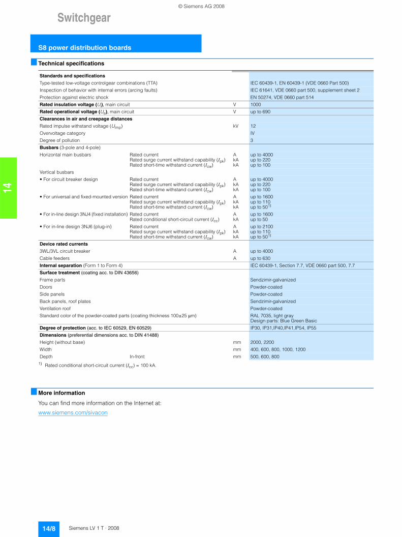
On (6): Reactive-power compensation up to 600 kvar
The reactive power compensation fields consist of a controller module and one or more capacitator modules.
Choked or unchoked controller units are available for reactive power compensation depending on the consumer type. Depending on the installed output and the ambient temperature, the installation of a floor fan can be necessary to reinforce the convection.
The capacitator modules are connected together and connected to the horizontal main busbar system via the link rails. The capacitator modules are mounted on the fuse switch disconnectors.
Installation of capacitator modules:• Unchoked up to 600 kvar per field• Choked up to 500 kvar per field
It is also possible to install a group switch module in order to enable the field for maintenance and review purposes from the main busbar system.
© Siemens AG 2008
Switchgear
S8 power distribution boards
14/8 Siemens LV 1 T · 2008
14
■ Technical specifications
1) Rated conditional short-circuit current (Icc) = 100 kA.
■ More information
You can find more information on the Internet at:
www.siemens.com/sivacon
Standards and specifications
Type-tested low-voltage controlgear combinations (TTA) IEC 60439-1, EN 60439-1 (VDE 0660 Part 500)
Inspection of behavior with internal errors (arcing faults) IEC 61641, VDE 0660 part 500, supplement sheet 2
Protection against electric shock EN 50274, VDE 0660 part 514
Rated insulation voltage (Ui), main circuit V 1000
Rated operational voltage (Ue), main circuit V up to 690
Clearances in air and creepage distances
Rated impulse withstand voltage (Uimp) kV 12
Overvoltage category IV
Degree of pollution 3
Busbars (3-pole and 4-pole)
Horizontal main busbars Rated current A up to 4000Rated surge current withstand capability (Ipk) kA up to 220Rated short-time withstand current (Icw) kA up to 100
Vertical busbars
• For circuit breaker design Rated current A up to 4000Rated surge current withstand capability (Ipk) kA up to 220Rated short-time withstand current (Icw) kA up to 100
• For universal and fixed-mounted version Rated current A up to 1600Rated surge current withstand capability (Ipk) kA up to 110Rated short-time withstand current (Icw) kA up to 501)
• For in-line design 3NJ4 (fixed installation) Rated current A up to 1600Rated conditional short-circuit current (Icc) kA up to 50
• For in-line design 3NJ6 (plug-in) Rated current A up to 2100Rated surge current withstand capability (Ipk) kA up to 110Rated short-time withstand current (Icw) kA up to 501)
Device rated currents
3WL/3VL circuit breaker A up to 4000
Cable feeders A up to 630
Internal separation (Form 1 to Form 4) IEC 60439-1, Section 7.7, VDE 0660 part 500, 7.7
Surface treatment (coating acc. to DIN 43656)
Frame parts Sendzimir-galvanized
Doors Powder-coated
Side panels Powder-coated
Back panels, roof plates Sendzimir-galvanized
Ventilation roof Powder-coated
Standard color of the powder-coated parts (coating thickness 100±25 µm) RAL 7035, light gray Design parts: Blue Green Basic
Degree of protection (acc. to IEC 60529, EN 60529) IP30, IP31,IP40,IP41,IP54, IP55
Dimensions (preferential dimensions acc. to DIN 41488)
Height (without base) mm 2000, 2200
Width mm 400, 600, 800, 1000, 1200
Depth In-front mm 500, 600, 800
© Siemens AG 2008
8US Busbar Systems
14/9Siemens LV 1 T · 2008
General data
14
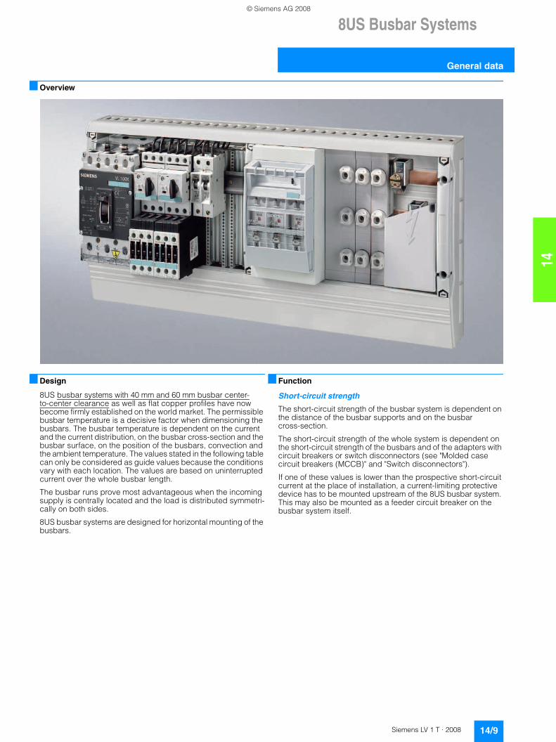
■ Overview
■ Design
8US busbar systems with 40 mm and 60 mm busbar center-to-center clearance as well as flat copper profiles have now become firmly established on the world market. The permissible busbar temperature is a decisive factor when dimensioning the busbars. The busbar temperature is dependent on the current and the current distribution, on the busbar cross-section and the busbar surface, on the position of the busbars, convection and the ambient temperature. The values stated in the following table can only be considered as guide values because the conditions vary with each location. The values are based on uninterrupted current over the whole busbar length.
The busbar runs prove most advantageous when the incoming supply is centrally located and the load is distributed symmetri-cally on both sides.
8US busbar systems are designed for horizontal mounting of the busbars.
■ Function
Short-circuit strength
The short-circuit strength of the busbar system is dependent on the distance of the busbar supports and on the busbar cross-section.
The short-circuit strength of the whole system is dependent on the short-circuit strength of the busbars and of the adapters with circuit breakers or switch disconnectors (see "Molded case circuit breakers (MCCB)" and "Switch disconnectors").
If one of these values is lower than the prospective short-circuit current at the place of installation, a current-limiting protective device has to be mounted upstream of the 8US busbar system. This may also be mounted as a feeder circuit breaker on the busbar system itself.
© Siemens AG 2008
8US Busbar Systems40 mm Busbar Systems
General data
14/10 Siemens LV 1 T · 2008
14
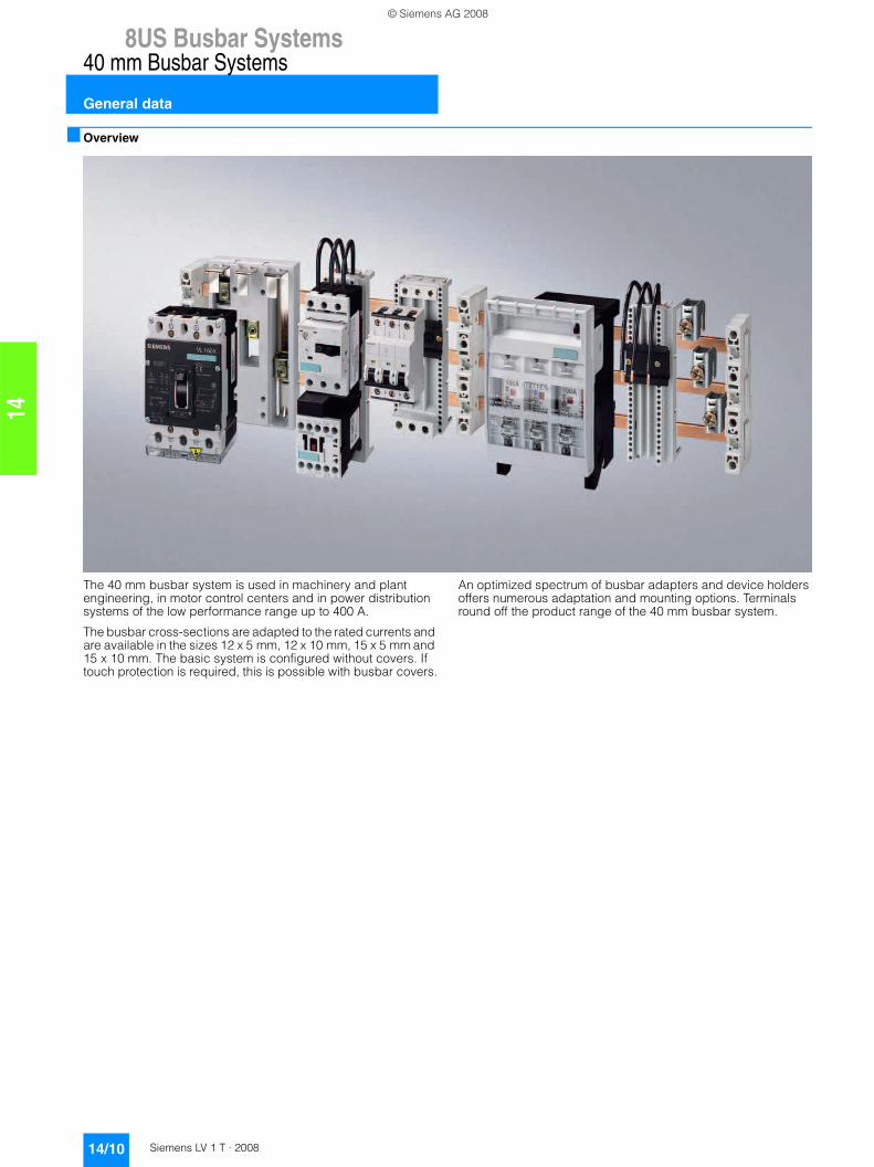
■ Overview
The 40 mm busbar system is used in machinery and plant engineering, in motor control centers and in power distribution systems of the low performance range up to 400 A.
The busbar cross-sections are adapted to the rated currents and are available in the sizes 12 x 5 mm, 12 x 10 mm, 15 x 5 mm and 15 x 10 mm. The basic system is configured without covers. If touch protection is required, this is possible with busbar covers.
An optimized spectrum of busbar adapters and device holders offers numerous adaptation and mounting options. Terminals round off the product range of the 40 mm busbar system.
© Siemens AG 2008
8US Busbar Systems
14/11Siemens LV 1 T · 2008
40 mm Busbar Systems
Base assemblies
14
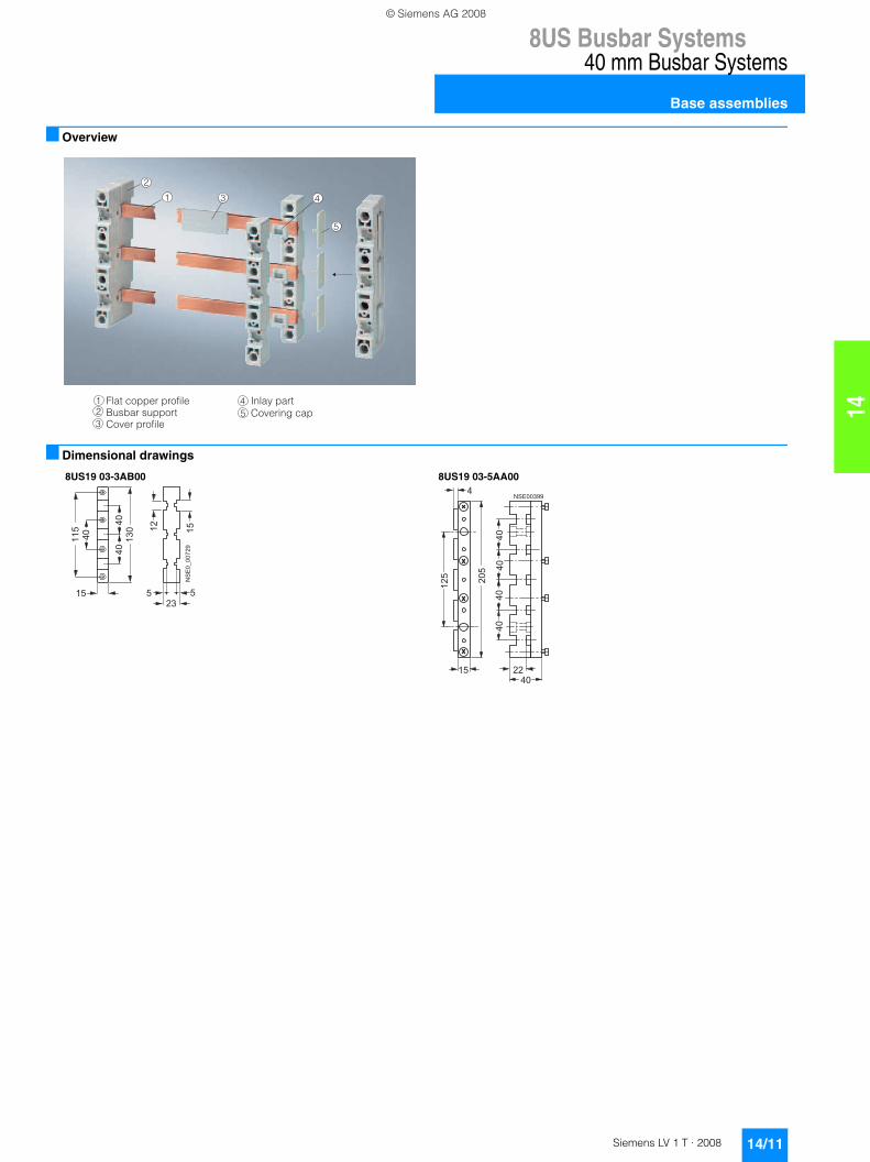
■ Overview
■ Dimensional drawings
2
3 4
5
1
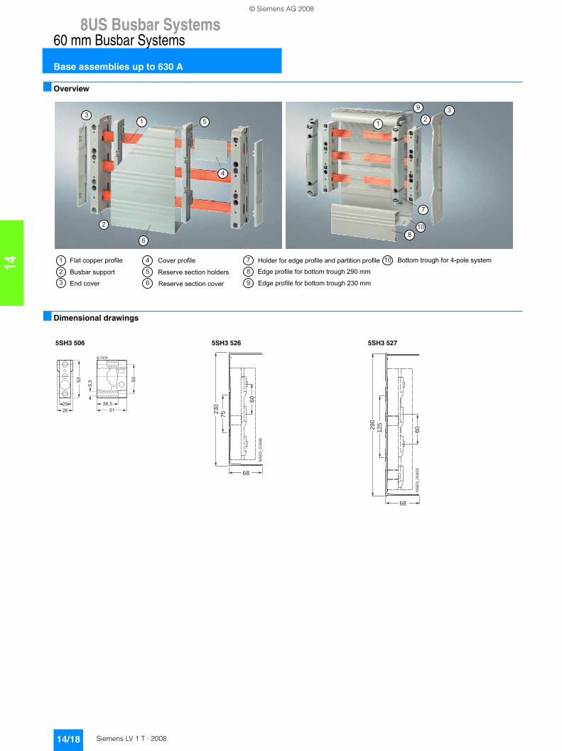
Flat copper profileBusbar supportCover profile
Inlay partCovering cap2
3
45
1
8US19 03-3AB00 8US19 03-5AA00
���
���
� �
� �
��
��
��
�
��
��
��������
�
��
��
���
��������
��
�����
��
�
© Siemens AG 2008
8US Busbar Systems40 mm Busbar Systems
Supply and connection technologies
14/12 Siemens LV 1 T · 2008
14
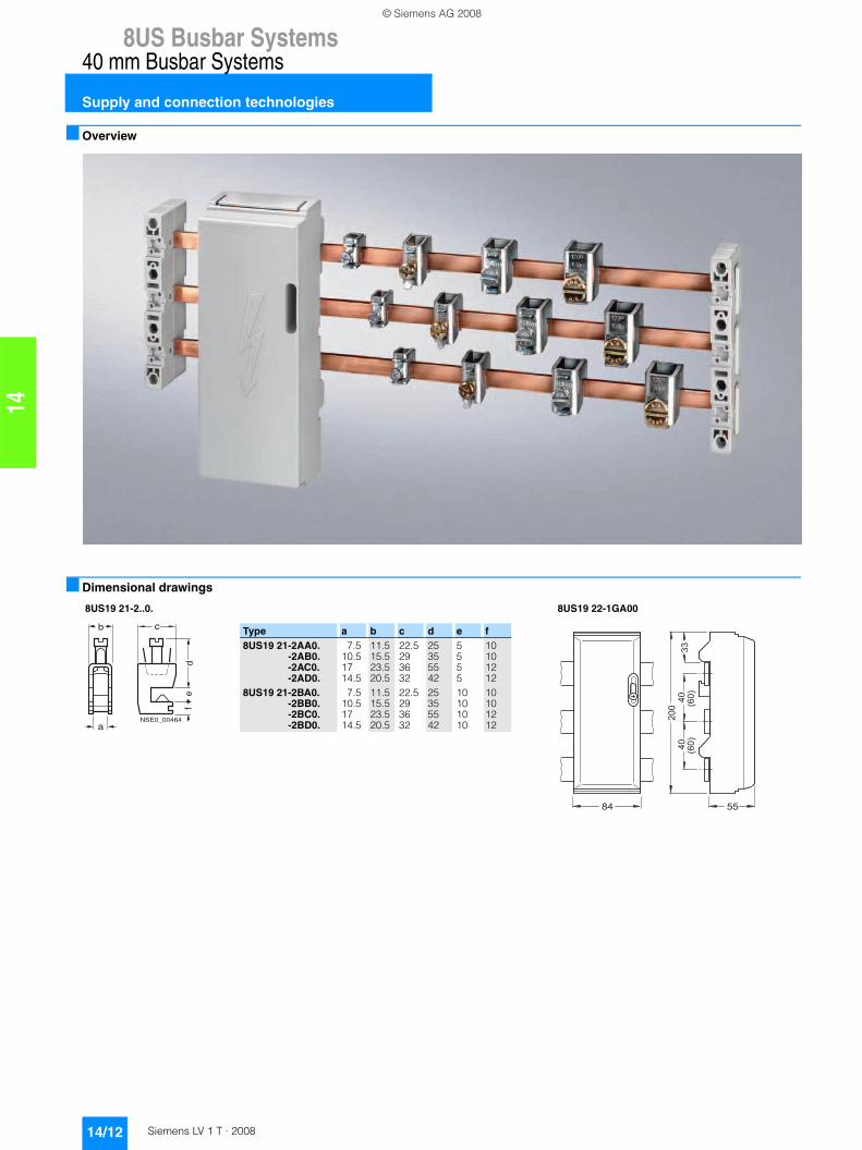
■ Overview
■ Dimensional drawings
8US19 21-2..0. 8US19 22-1GA00
NSE0_00464
b
a
c
de
f
Type a b c d e f8US19 21-2AA0.
-2AB0.-2AC0.-2AD0.
7.510.51714.5
11.515.523.520.5
22.5293632
25355542
5555
10101212
8US19 21-2BA0.-2BB0.-2BC0.-2BD0.
7.510.51714.5
11.515.523.520.5
22.5293632
25355542
10101010
10101212
���
� �
��
��
� �
���
��
���
© Siemens AG 2008
8US Busbar Systems
14/13Siemens LV 1 T · 2008
40 mm Busbar Systems
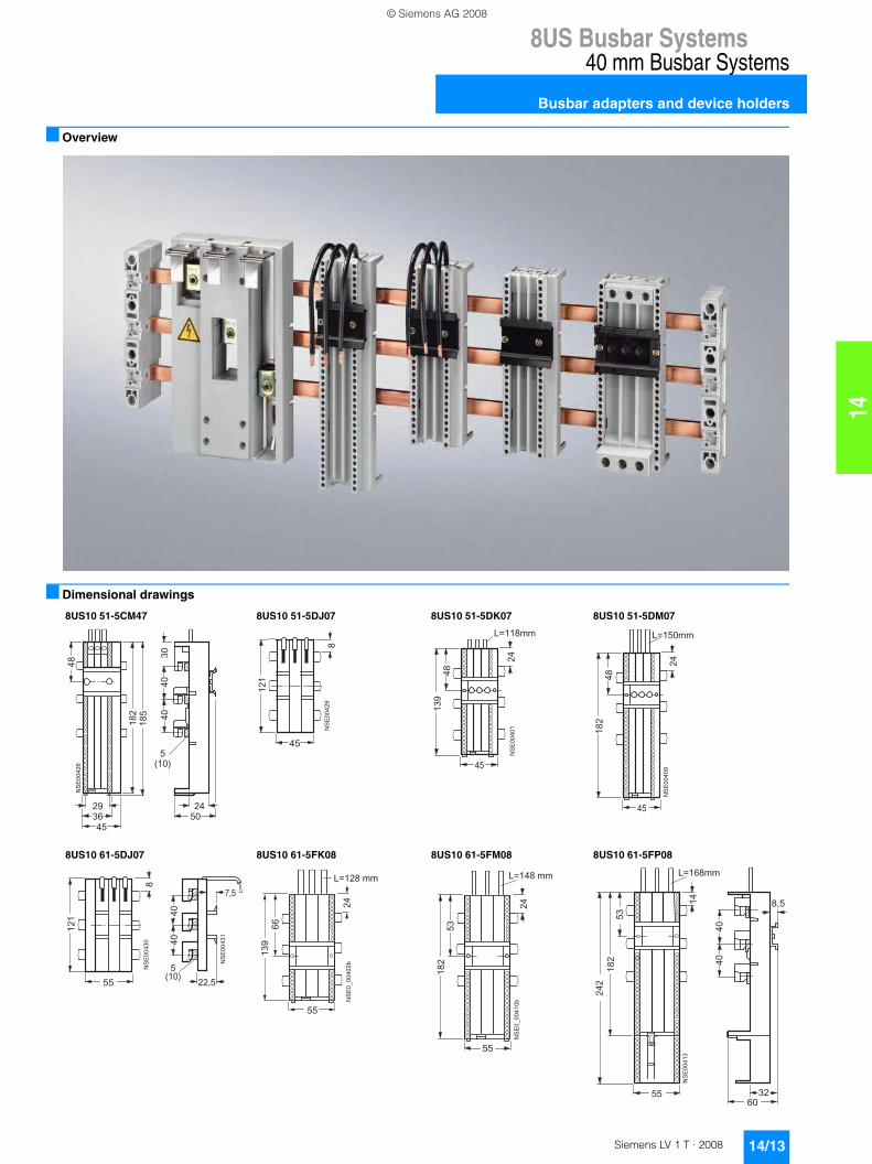
Busbar adapters and device holders
14
■ Overview
■ Dimensional drawings
8US10 51-5CM47 8US10 51-5DJ07 8US10 51-5DK07 8US10 51-5DM07
��
����
���
���
�
�
�
�����
����
�
�
�
�
���
��
�
��
�
��
�
���
��
��
���
�������
��
�
�
�
�
��
��
������
��
���
8US10 61-5DJ07 8US10 61-5FK08 8US10 61-5FM08 8US10 61-5FP08
���
��
�
��
�
�
�
�
����
�
�
�
��
���
����
�����������
� � � � �
� �
���
��
��
�����������
���
��
� �
� � � � �
��
��
��
��
��
��
�
��
��
�
� �����
���
��
��
© Siemens AG 2008
8US Busbar Systems40 mm Busbar Systems
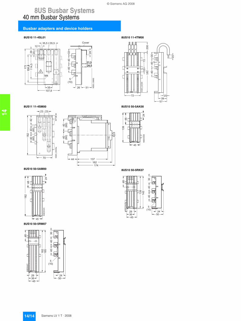
Busbar adapters and device holders
14/14 Siemens LV 1 T · 2008
14
8US10 11-4SL01 8US10 11-4TM00
8US11 11-4SM00 8US10 50-5AK00
8US10 50-5AM00 8US10 50-5RK07
8US10 50-5RM07
7239
40
40
18
22
00
73
15
NS
E0
_0
15
94
30
5
15
15
57
�����������
�
� �
�
�
� �
� �
�
��
��
��
� �
� �
����
����
��
��
����
����
��
��
��
��
��
��
�
��
��
��
��
��
��
��
��
��
��
�
��
���
��
��
�
������
�����
��
���
��
��
��
��
���
��
��
�
������
����
��
��
��
��
© Siemens AG 2008
8US Busbar Systems
14/15Siemens LV 1 T · 2008
40 mm Busbar Systems
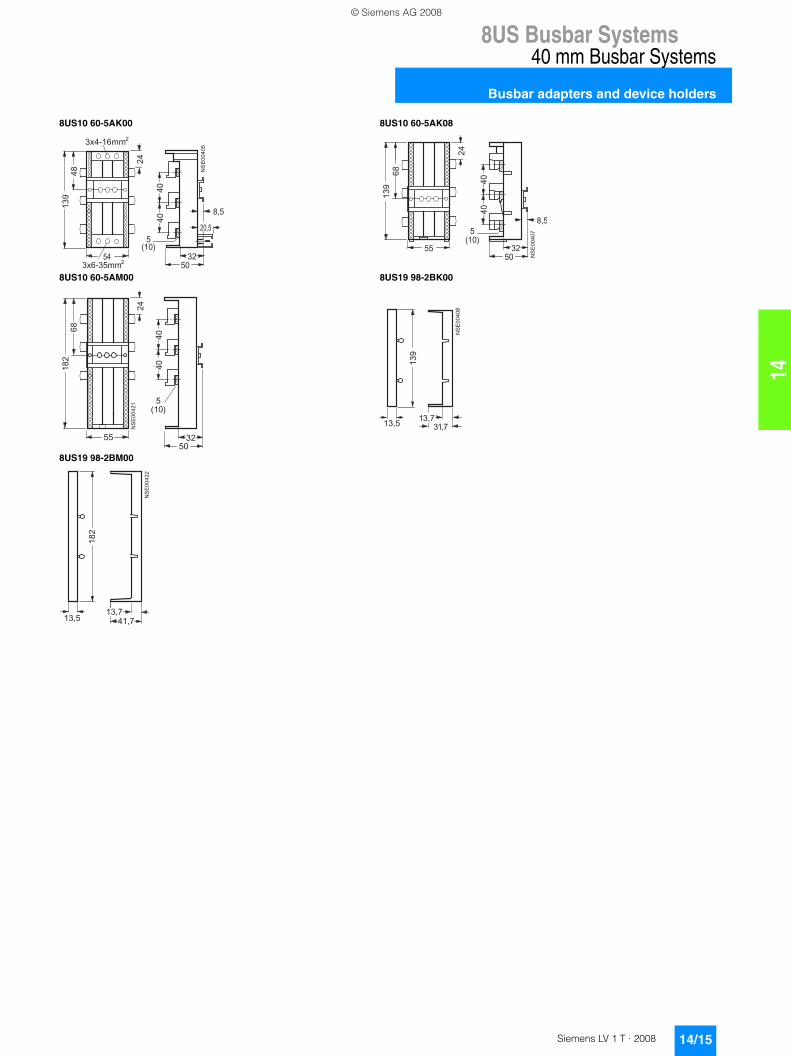
Busbar adapters and device holders
14
8US10 60-5AK00 8US10 60-5AK08
8US10 60-5AM00 8US19 98-2BK00
8US19 98-2BM00
��
��
��
������
��
��
��
�
����
�
�������
������� ��
���
����
��
��
��
��
��
��
��
�
���
����
���
��
��
��
��
��
�
��
��
��
��
��
���
����
��
��
��
��
��
�
�� ����
��
�� ���
��
��
��
��
��
© Siemens AG 2008
8US Busbar Systems40 mm Busbar Systems
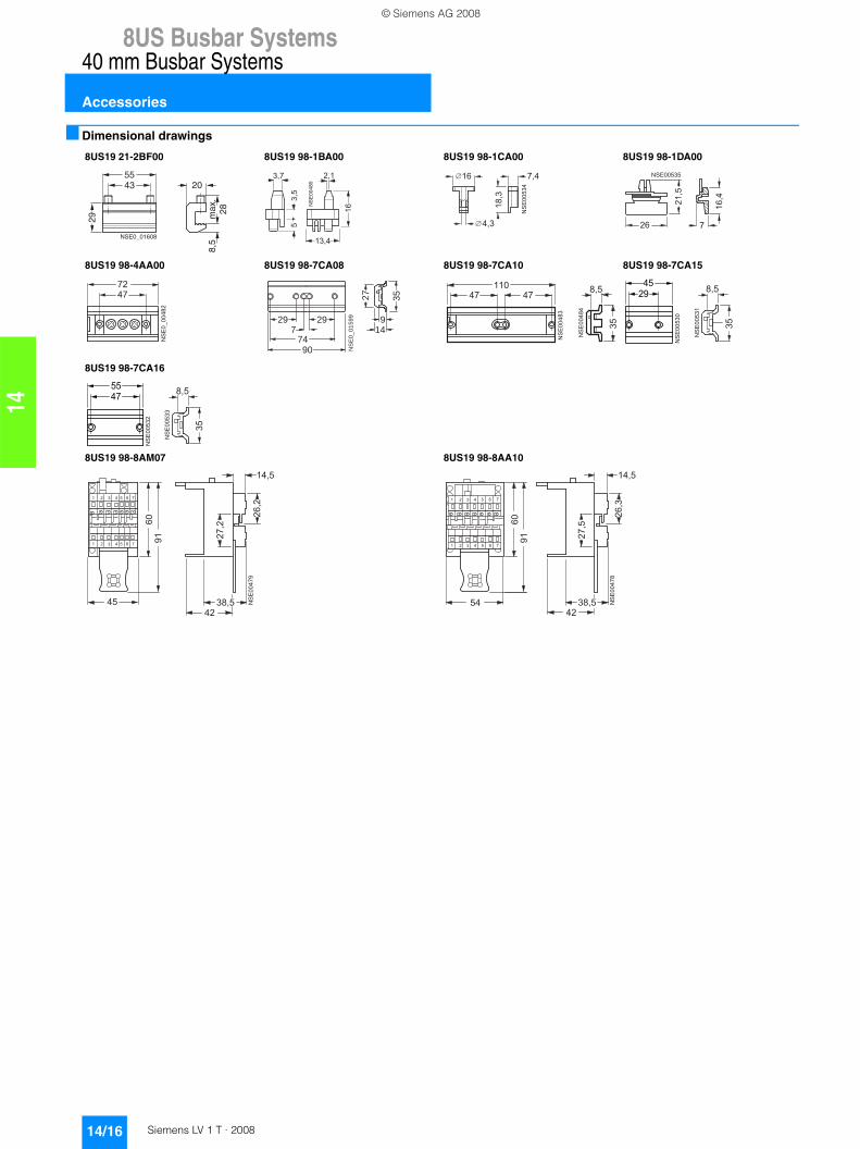
Accessories
14/16 Siemens LV 1 T · 2008
14
■ Dimensional drawings
8US19 21-2BF00 8US19 98-1BA00 8US19 98-1CA00 8US19 98-1DA00
8US19 98-4AA00 8US19 98-7CA08 8US19 98-7CA10 8US19 98-7CA15
8US19 98-7CA16
8US19 98-8AM07 8US19 98-8AA10
NSE0_01608
29
4355
20
max
.28
8,5
��
��
��
��
��
��
��
�
�
�� ��
���
���
��
��
��
��
�
��
�������
���
���
�
� �
� �
���������
29
7490
729 9
14
27
35
NS
E0
_0
15
99
�������
��
��
��
�
��
��
��
��
�� � �
��
��
�
�
��
��
�
�
��
��
��
��
�
�
��
���
��
��
��
��
�
�
��
����
��
� � � �
� � � � �
� ����
���
��� ��
��
��
��
�
�����
��
� � � �
� � � � �
� ���
���
���
© Siemens AG 2008
8US Busbar Systems
14/17Siemens LV 1 T · 2008
60 mm Busbar Systems
General data
14
■ Overview
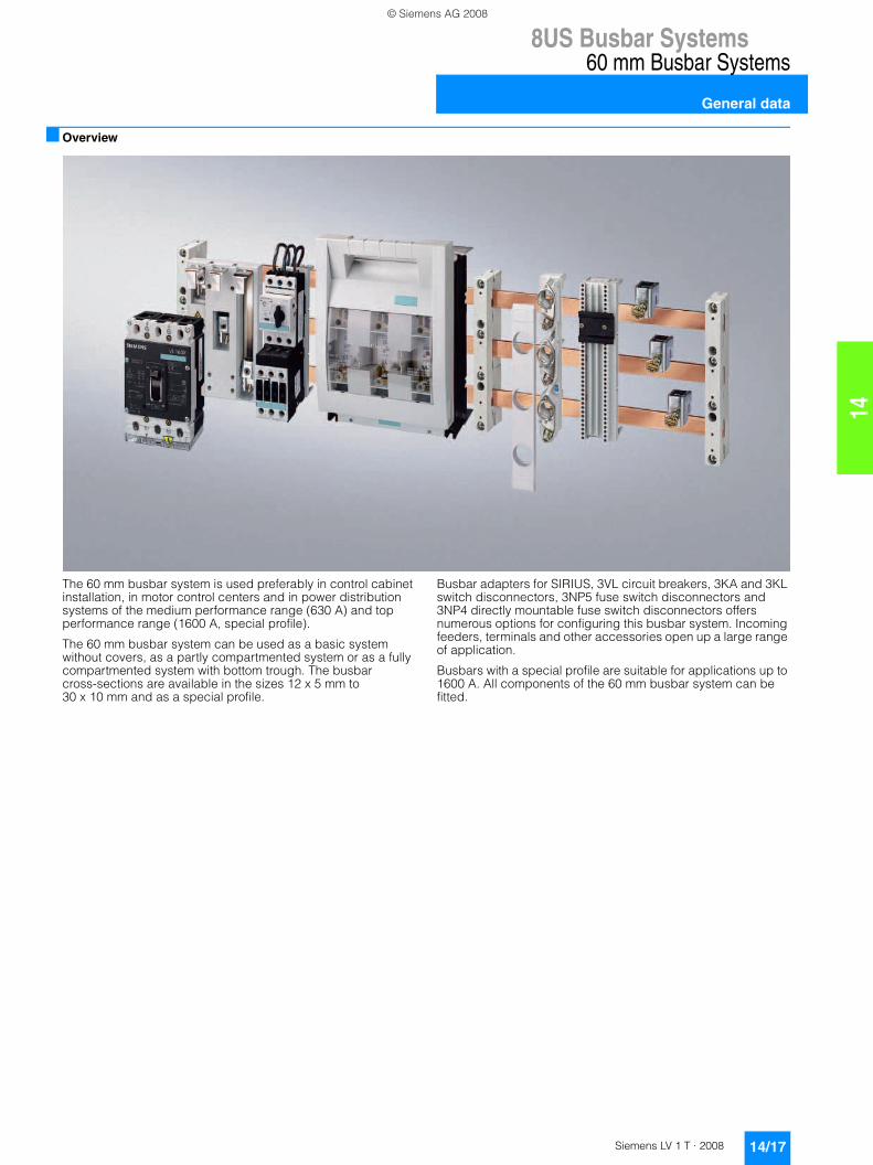
The 60 mm busbar system is used preferably in control cabinet installation, in motor control centers and in power distribution systems of the medium performance range (630 A) and top performance range (1600 A, special profile).
The 60 mm busbar system can be used as a basic system without covers, as a partly compartmented system or as a fully compartmented system with bottom trough. The busbar cross-sections are available in the sizes 12 x 5 mm to30 x 10 mm and as a special profile.
Busbar adapters for SIRIUS, 3VL circuit breakers, 3KA and 3KL switch disconnectors, 3NP5 fuse switch disconnectors and 3NP4 directly mountable fuse switch disconnectors offers numerous options for configuring this busbar system. Incoming feeders, terminals and other accessories open up a large range of application.
Busbars with a special profile are suitable for applications up to 1600 A. All components of the 60 mm busbar system can be fitted.
© Siemens AG 2008
8US Busbar Systems60 mm Busbar Systems
Base assemblies up to 630 A
14/18 Siemens LV 1 T · 2008
14
■ Overview
■ Dimensional drawings
5SH3 506 5SH3 526 5SH3 527
��
��
�
��
�
�
�������
��
68
75
60
23
0
NS
E0
_0
16
00
68
12
5
29
0
60
NS
E0
_0
16
03
© Siemens AG 2008
8US Busbar Systems
14/19Siemens LV 1 T · 2008
60 mm Busbar Systems
Base assemblies up to 630 A
14
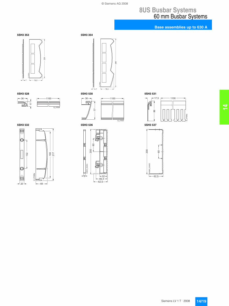
5SH3 353 5SH3 354
5SH3 528 5SH3 530 5SH3 531
5SH3 532 5SH3 536 5SH3 537
���
���
��
� ���
��
�
���
���
��
� ���
�
�
��
� ����
��������
��������
��
� ���� ����
�
����
���
���
��
�
�
�
��
�
��
�
���
���
��
9
49,432
62,5
60
20
0
NS
E0
_0
16
01
62,5
60
20
0N
SE
0_
01
60
2
© Siemens AG 2008
8US Busbar Systems60 mm Busbar Systems
Base assemblies up to 630 A
14/20 Siemens LV 1 T · 2008
14
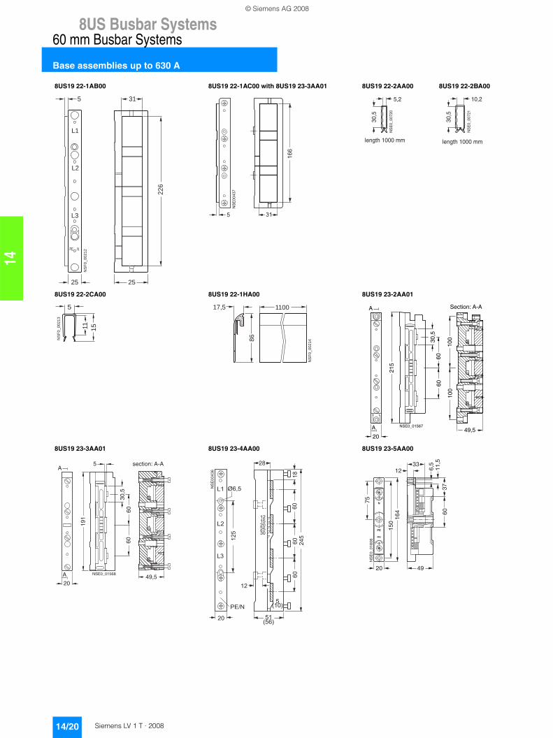
8US19 22-1AB00 8US19 22-1AC00 with 8US19 23-3AA01 8US19 22-2AA00 8US19 22-2BA00
8US19 22-2CA00 8US19 22-1HA00 8US19 23-2AA01
8US19 23-3AA01 8US19 23-4AA00 8US19 23-5AA00
226
25
NS
F0_0
0212
L1
PE N
L3
25
5 31
L2
��
���
�
��
��
�
�
NS
E0_
0072
0
5,2
30,5
length 1000 mm
10,2
30,5
NS
E0_
0072
1
length 1000 mm
1511
5
NS
F0_0
0213
17,5
86
1100N
SF0
_002
14
6060
30,5
215
A
2049,5
100
100
A
NSE0_01567
Section: A-A
60
A
A
5
49,5
6030
,5
191
20
NSE0_01568
section: A-A
�� �����
���
����
��
��
��
��
��
��
�
��
��
��
��
����
��
��
��
����������
����
11,5
3760
49
6,5
1233
20
150
75
164
NS
E0_
0160
6
© Siemens AG 2008
8US Busbar Systems
14/21Siemens LV 1 T · 2008
60 mm Busbar Systems
Base assemblies up to 1600 A
14
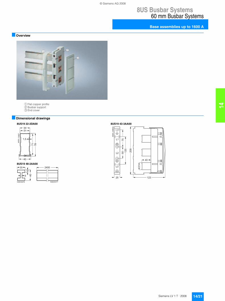
■ Overview
■ Dimensional drawings
3
1 2
1
3
Flat copper profileBusbar supportEnd cover
2
8US19 22-2DA00 8US19 43-3AA00
8US19 48-2AA00
1,5
3431
40
71 78
NS
E0_
0160
7
� �
� �
� �
���������
��
��
� �
��
��
� � � � �
���
��������
��
��
�
�
���
��������
© Siemens AG 2008
8US Busbar Systems60 mm Busbar Systems
Supply and connection technologies
14/22 Siemens LV 1 T · 2008
14
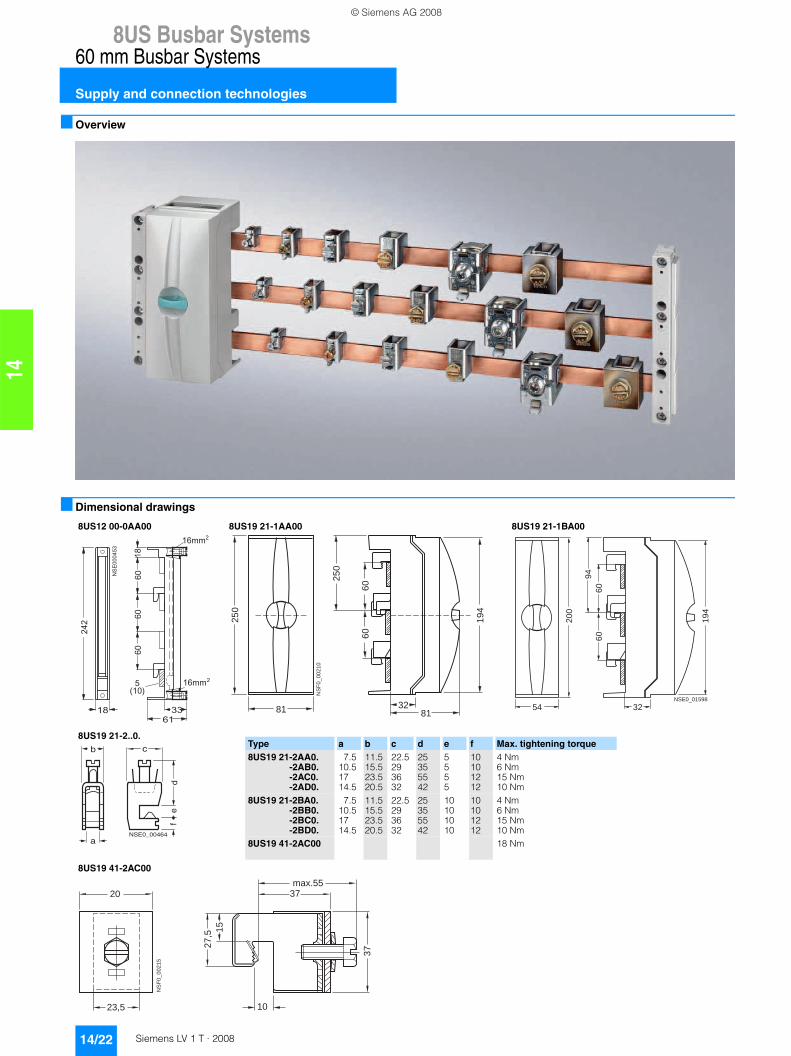
■ Overview
■ Dimensional drawings
8US12 00-0AA00 8US19 21-1AA00 8US19 21-1BA00
8US19 21-2..0.
8US19 41-2AC00
�
��
��
��
�
��
��
��
���
���
�
� ��
���
���
25
0
81 81
25
0
19
4
60
60
32
NS
F0
_0
02
10
20
0
19
454
60
94
60
32NSE0_01598
NSE0_00464
b
a
c
de
f
Type a b c d e f Max. tightening torque8US19 21-2AA0.
-2AB0.-2AC0.-2AD0.
7.510.51714.5
11.515.523.520.5
22.5293632
25355542
5555
10101212
4 Nm6 Nm15 Nm10 Nm
8US19 21-2BA0.-2BB0.-2BC0.-2BD0.
7.510.51714.5
11.515.523.520.5
22.5293632
25355542
10101010
10101212
4 Nm6 Nm15 Nm10 Nm
8US19 41-2AC00 18 Nm
20max.55
37
37
27,5 15
23,5 10
NS
F0_0
0215
© Siemens AG 2008
8US Busbar Systems
14/23Siemens LV 1 T · 2008
60 mm Busbar Systems
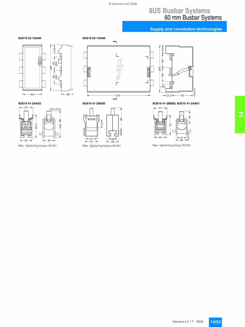
Supply and connection technologies
14
8US19 22-1GA00 8US19 22-1GA02
8US19 41-2AA02
Max. tightening torque 30 Nm
8US19 41-2BA00
Max. tightening torque 40 Nm
8US19 41-2BB00, 8US19 41-2AA01
Max. tightening torque 30 Nm
���
� �
��
��
� �
���
��
���
��
��
��
�����
�� ��
��
� �
��
��
� � � � � � � � � �
�
�� �
� �
������
� �
��
��
��
��
���
���
��
�
��
��
��
��
��
�
��
��
�
�
© Siemens AG 2008
8US Busbar Systems60 mm Busbar Systems
Busbar adapters and device holders
14/24 Siemens LV 1 T · 2008
14
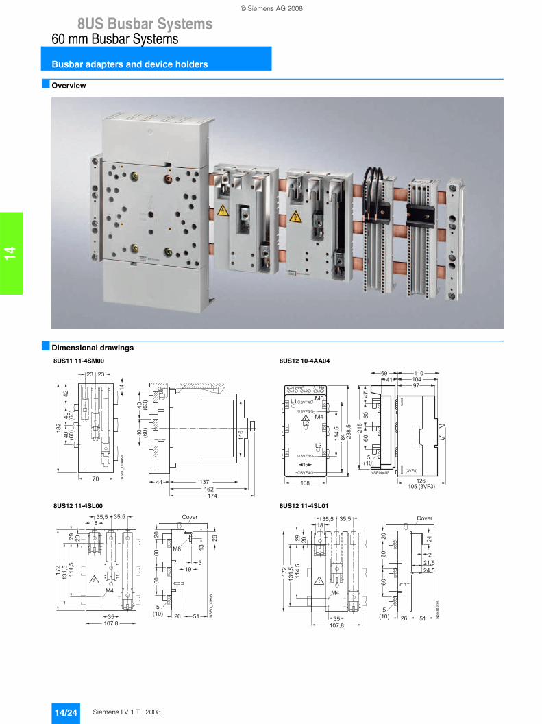
■ Overview
■ Dimensional drawings
8US11 11-4SM00 8US12 10-4AA04
8US12 11-4SL00 8US12 11-4SL01
�����������
�
� �
�
�
� �
� �
�
��
��
��
� �
� �
����
����
��
��
����
����
�����
��� �����
��
������
��
���
� ��
� ��
��
��
�� ��
��
� ��
� ��
������� ������
��
��
����
��
��
���
�����
���
������ ���
�����
��
�� ���
���
�
�����
���
��
� �
� ��
�
� � � � �
� �
� � � � � � �
�� �
� �
�
� �
� �
� � �
�� � �
� � � � �
© Siemens AG 2008
8US Busbar Systems
14/25Siemens LV 1 T · 2008
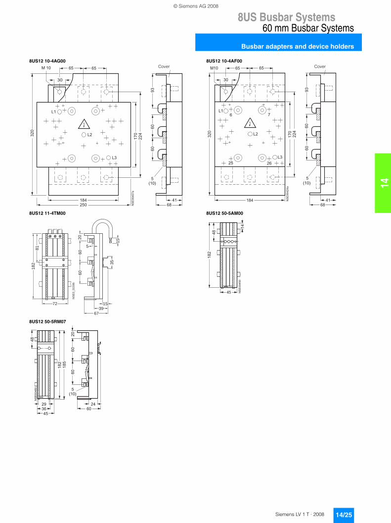
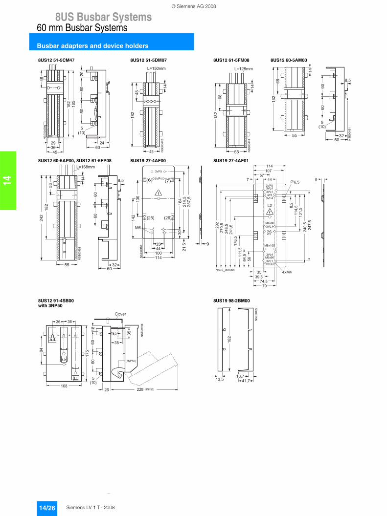
60 mm Busbar Systems
Busbar adapters and device holders
14
8US12 10-4AG00 8US12 10-4AF00
8US12 11-4TM00 8US12 50-5AM00
8US12 50-5RM07
�
������
��
��
��
��
������
��
�
��������
��
���
�
��
��
����
�����
��
Cover
��
��
����
��
�����
��� �
��
��
��
���
��
���
�� ��
���
��
��
��
���
� �
�� ��
Cover
72
81
18
2
NS
E0
_0
15
96
60
35
60
20
15
5
3915
67
�
�
��
��
��
��
���
��
��
��
�����
��
��
����
���
������
�
�
��
��
����
© Siemens AG 2008
8US Busbar Systems60 mm Busbar Systems
Busbar adapters and device holders
14/26 Siemens LV 1 T · 2008
14
8US12 51-5CM47 8US12 51-5DM07 8US12 61-5FM08 8US12 60-5AM00
8US12 60-5AP00, 8US12 61-5FP08 8US19 27-4AF00 8US19 27-4AF01
8US12 91-4SB00with 3NP50
8US19 98-2BM00
��
��
�����
��
��
����
���
������
�
�
��
��
����
�
�
��
��
��
��
���
��
�������
�
�
��
��
���
��
��
�������
��
�
�
��
��
���
��
��
��
����
���
��
��
�����
�
�
��
��
���
��
��
��
���
��
��
���
�������
����
���
�����
�����
����
�
�
�
��
��
��
���
���
����
��
������
� ��
� ����� ���
���� ����
� � � �
� � �� � �
����
����
� � �
� � �
� � � �
� � �
� � � �
� � � �
� �
� � �
� � � �
� � � �
����
����
����
���� ���
�� �
�
���
����
�� �
� � ��
� � �
� � �
� �
� � �
�
� �
� � �
�� �
�� �
�
� � � �
� � � �
� � � � � � �
���
��
��
��
�
�
�
�
��
�
�
��
�
��
���
� ��
�������
�������
�����
Cover
��
���� ����
��
��
��
��
����
© Siemens AG 2008
8US Busbar Systems
14/27Siemens LV 1 T · 2008
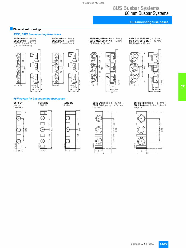
60 mm Busbar Systems
Bus-mounting fuse bases
14
■ Dimensional drawings
5SG6, 5SF6 bus-mounting fuse bases
5SH covers for bus-mounting fuse bases
5SG6 202 (t = 5 mm), 5SG6 203 (t = 10 mm) D02/63 A (a = 27 mm) (t = bar thickness)
5SG6 204 (t = 5 mm), 5SG6 205 (t = 10 mm) D02/63 A (a = 42 mm)
5SF6 014, 5SF6 015 (t = 5 mm), 5SF6 016, 5SF6 017 (t = 10 mm) DII/25 A (a = 57 mm)
5SF6 214, 5SF6 215 (t = 5 mm), 5SF6 216, 5SF6 217 (t = 10 mm) DIII/63 A (a = 42 mm)
6060
177
a
I2_0
7478
a
23t
33,555
6060
177
a I2_0
7498
23t
33,555
6060
169
a I2_0
7497
3643,5
t
66
��
��
��
�
� ���
�
��
��
��
�
��
5SH5 241 single D02/63 A
5SH5 242 1.33-fold
5SH5 243 double
5SH2 042 (single: a = 42 mm) 5SH2 043 (double: b = 84 mm) DII/25 A
5SH2 242 (single: a = 57 mm) 5SH2 243 (double: b = 114 mm) DIII/63 A
��
��
��
�
���
�
��
�
��
��
��
��
�
���
�
��
��
��
��
�
���
�
��
�
��
��
��
�
���
�
��
�
�
��
��
��
�
���
�
��
�
© Siemens AG 2008
8US Busbar Systems60 mm Busbar Systems
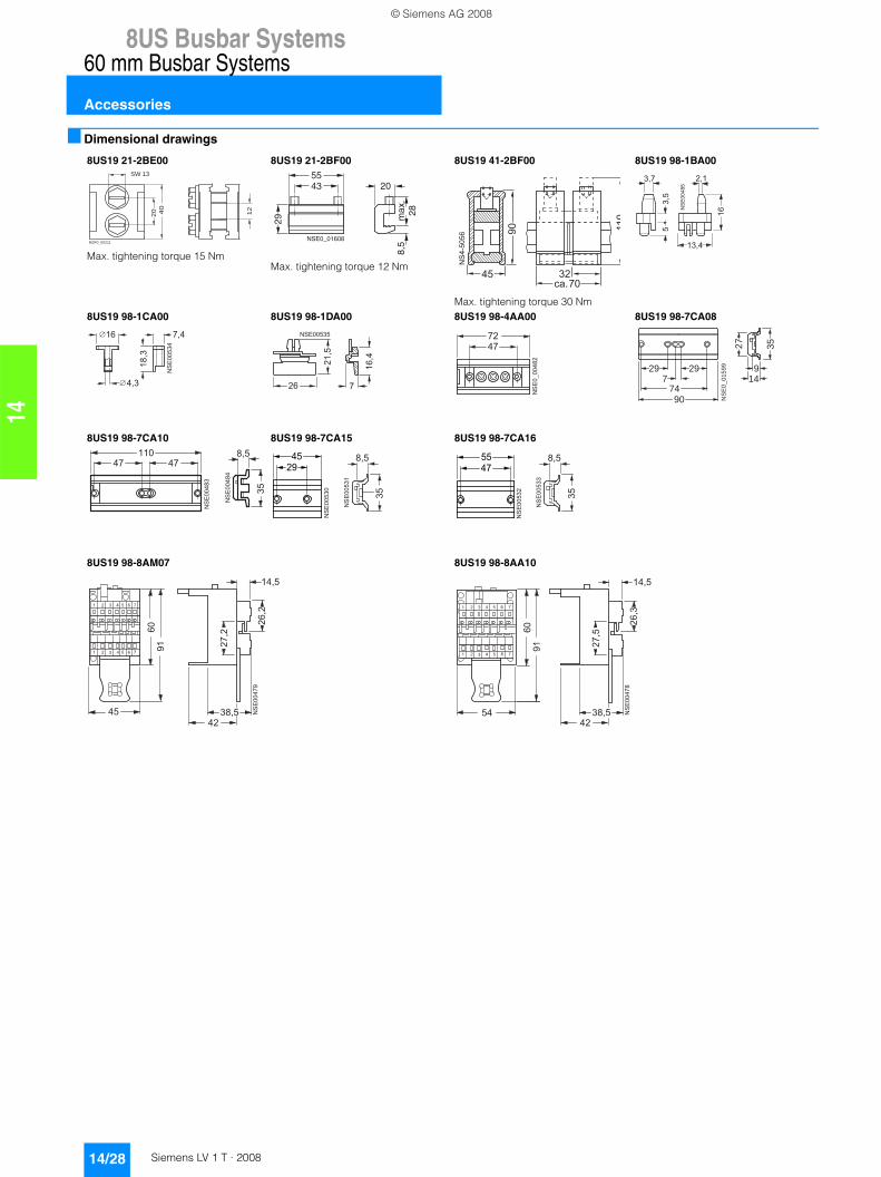
Accessories
14/28 Siemens LV 1 T · 2008
14
■ Dimensional drawings
8US19 21-2BE00
Max. tightening torque 15 Nm
8US19 21-2BF00
Max. tightening torque 12 Nm
8US19 41-2BF00
Max. tightening torque 30 Nm
8US19 98-1BA00
8US19 98-1CA00 8US19 98-1DA00 8US19 98-4AA00 8US19 98-7CA08
8US19 98-7CA10 8US19 98-7CA15 8US19 98-7CA16
8US19 98-8AM07 8US19 98-8AA10
20 40
12
SW 13
NSF0_00211NSE0_01608
29
4355
20
max
.28
8,5
�� ������
��
�
���
���
��
��
��
��
��
�
�
�
��
�
���
��
��
��
��
��
��
�
�
������� ��
���
�
� �
� �
���������
29
7490
729 9
14
27
35
NS
E0
_0
15
99
�������
��
��
��
�
��
��
��
��
��
� �
��
��
�
�
��
����
����
��
��
�
�
��
��
�
��
��
��
��
�
�
��
����
��
� � � �
� � � � �
� ����
���
��� ��
��
��
��
�
��
���
��
� � � �
� � � � �
� ���
���
���
© Siemens AG 2008
8UC Door-Coupling Rotary Operating Mechanisms
14/29Siemens LV 1 T · 2008
General data
14
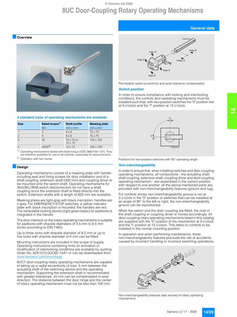
■ Overview
4 standard sizes of operating mechanisms are available:
1) Operating mechanisms tested with triple torque (VDE 0660 Part 107). They are therefore qualified for use in all controls, especially for disconnectors.
2) Operation with two hands.
■ Design
Operating mechanisms consist of a masking plate with handle including seal and fixing screws for door installation and of a shaft coupling, extension shaft (300 mm) and coupling driver to be mounted onto the switch shaft. Operating mechanisms for 3KA/3KL/3KM switch disconnectors do not have a shaft coupling since the extension shaft is fitted directly into the switch. Extension shafts with a length of 600 mm are available.
Masking plates are light-gray with black inscription, handles are ti-grey. For EMERGENCY-STOP switches, a yellow indicator plate with black inscription is mounted; the handles are red. The retractable locking device (light green basic) for padlocks is integrated in the handle.
The door interlock on the rotary operating mechanisms is suitable for padlocks with shackle diameters of 4.5 mm to 8.5 mm (locks according to DIN 7465).
Up to three locks with shackle diameter of 8.5 mm or up to five locks with shackle diameter of 6 mm can be fitted.
Mounting instructions are included in the scope of supply. Operating instructions containing hints on activation or modification of interlocking conditions are available by quoting Order No. 8ZX1012-0UC60-1AA1 or can be downloaded from:www.siemens.com/lowvoltage
8UC7 door-coupling rotary operating mechanisms are capable of taking up a radial eccentricity of max. 5 mm between the actuating shaft of the switching device and the operating mechanism. Supporting the extension shaft is recommended with greater tolerances. ±5 mm can be compensated in axial direction. The distance between the door hinge and the center of rotary operating mechanism must not be less than 100 mm.
Permissible radial eccentricity and axial tolerance compensation
Switch position
In order to ensure compliance with locking and interlocking conditions, the controls and operating mechanisms must be installed such that, with two-position switches the "0" position lies at 9 o'clock and the "I" position at 12 o'clock.
Positions for two-position switches with 90° operating angle
Non-interchangeability
In order to ensure that, when installing switches and door-coupling operating mechanisms, all components - the actuating shaft, shaft coupling, extension shaft, coupling driver and door-coupling operating mechanism - are assembled in the correct position with respect to one another, all the above-mentioned parts are provided with non-interchangeability features (groove and lug).
For controls whose non-interchangeability groove is not at 3 o'clock in the "0" position or switches that can be installed at an angle of 90° to the left or right, the non-interchangeability groove can be repositioned.
When the switch and the door coupling are fitted, the rivet in the shaft coupling or coupling driver is moved accordingly. All door-coupling rotary operating mechanisms listed in this catalog are supplied with the "0" position of the mechanism at 9 o'clock and the "I" position at 12 o'clock. This refers to controls to be installed in the normal mounting position.
In operation and when performing maintenance, these non-interchangeability features preclude the risk of accidents caused by incorrect handling or incorrect switching operations.
Non-interchangeability features (see arrows) of rotary operating mechanisms
Size Rated torque1) Shaft profile Masking plate Nm mm x mm mm x mm
1 4 6 x 6 75 x 752 9 8 x 8 75 x 753 25 10 x 10 or
12 x 12100 x 100
4 40/552) 12 x 12 100 x 100
������
����
����
����
����
�����
�����
��
���
�
������
������
© Siemens AG 2008
8UC Door-Coupling Rotary Operating Mechanisms
General data
14/30 Siemens LV 1 T · 2008
14
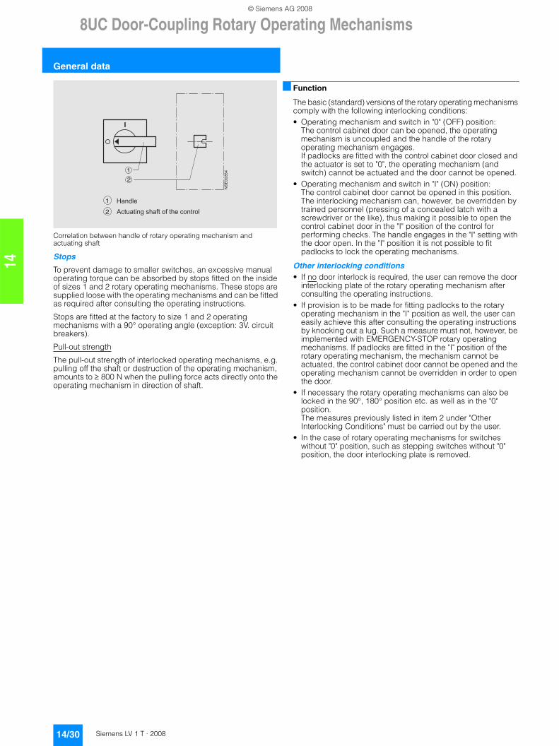
Correlation between handle of rotary operating mechanism and actuating shaft
Stops
To prevent damage to smaller switches, an excessive manual operating torque can be absorbed by stops fitted on the inside of sizes 1 and 2 rotary operating mechanisms. These stops are supplied loose with the operating mechanisms and can be fitted as required after consulting the operating instructions.
Stops are fitted at the factory to size 1 and 2 operating mechanisms with a 90° operating angle (exception: 3V. circuit breakers).
Pull-out strength
The pull-out strength of interlocked operating mechanisms, e.g. pulling off the shaft or destruction of the operating mechanism, amounts to ≥ 800 N when the pulling force acts directly onto the operating mechanism in direction of shaft.
■ Function
The basic (standard) versions of the rotary operating mechanisms comply with the following interlocking conditions:• Operating mechanism and switch in "0" (OFF) position:
The control cabinet door can be opened, the operating mechanism is uncoupled and the handle of the rotary operating mechanism engages. If padlocks are fitted with the control cabinet door closed and the actuator is set to "0", the operating mechanism (and switch) cannot be actuated and the door cannot be opened.
• Operating mechanism and switch in "I" (ON) position: The control cabinet door cannot be opened in this position. The interlocking mechanism can, however, be overridden by trained personnel (pressing of a concealed latch with a screwdriver or the like), thus making it possible to open the control cabinet door in the "I" position of the control for performing checks. The handle engages in the "I" setting with the door open. In the "I" position it is not possible to fit padlocks to lock the operating mechanisms.
Other interlocking conditions• If no door interlock is required, the user can remove the door
interlocking plate of the rotary operating mechanism after consulting the operating instructions.
• If provision is to be made for fitting padlocks to the rotary operating mechanism in the "I" position as well, the user can easily achieve this after consulting the operating instructions by knocking out a lug. Such a measure must not, however, be implemented with EMERGENCY-STOP rotary operating mechanisms. If padlocks are fitted in the "I" position of the rotary operating mechanism, the mechanism cannot be actuated, the control cabinet door cannot be opened and the operating mechanism cannot be overridden in order to open the door.
• If necessary the rotary operating mechanisms can also be locked in the 90°, 180° position etc. as well as in the "0" position. The measures previously listed in item 2 under "Other Interlocking Conditions" must be carried out by the user.
• In the case of rotary operating mechanisms for switches without "0" position, such as stepping switches without "0" position, the door interlocking plate is removed.
NS
E00
3541
2
� � � � � �1
� � � � � � � � � � � � � � � � � � � �2
© Siemens AG 2008
8UC Door-Coupling Rotary Operating Mechanisms
14/31Siemens LV 1 T · 2008
For 3K switch disconnectors
14
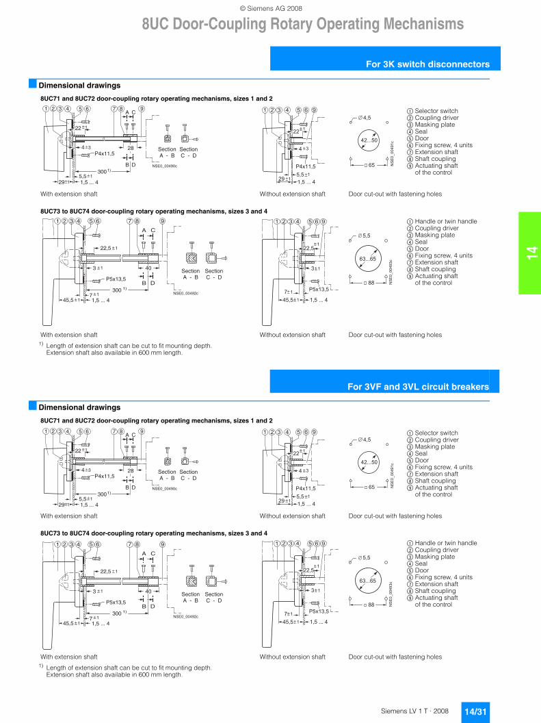
■ Dimensional drawings
1) Length of extension shaft can be cut to fit mounting depth. Extension shaft also available in 600 mm length.
■ Dimensional drawings
1) Length of extension shaft can be cut to fit mounting depth. Extension shaft also available in 600 mm length.
8UC71 and 8UC72 door-coupling rotary operating mechanisms, sizes 1 and 2
With extension shaft Without extension shaft Door cut-out with fastening holes
8UC73 to 8UC74 door-coupling rotary operating mechanisms, sizes 3 and 4
With extension shaft Without extension shaft Door cut-out with fastening holes
29 1,5 ... 45,5
3001)
P4x11,54 3
B D
28
22
A C1 2 3 4 5 6 7 8 9
NSE0_00490c
1
11
SectionA - B
SectionC - D
����������
��� � �
�� �
�
� � � � � � �
� � �
� � � � � � � � �� � �
� � �
� � � � � � �
�
�
$ Selector switch % Coupling driver & Masking plate ( Seal ) Door * Fixing screw, 4 units + Extension shaft , Shaft coupling - Actuating shaft
of the control
B
A C
1)
4321 5 6 987
D
1
1
1145,5 1,5 ... 4
7
3 40
P5x13,5
22,5
NSE0_00492c300
SectionA - B
SectionC - D
��� � �
�
� � � �
�
� � � � � �� �
� � � � � � � � �� � � � �
� � ���������
� � �
� � � �
$ Handle or twin handle % Coupling driver & Masking plate ( Seal ) Door * Fixing screw, 4 units + Extension shaft , Shaft coupling - Actuating shaft
of the control
For 3VF and 3VL circuit breakers
8UC71 and 8UC72 door-coupling rotary operating mechanisms, sizes 1 and 2
With extension shaft Without extension shaft Door cut-out with fastening holes
8UC73 to 8UC74 door-coupling rotary operating mechanisms, sizes 3 and 4
With extension shaft Without extension shaft Door cut-out with fastening holes
29 1,5 ... 45,5
3001)
P4x11,54 3
B D
28
22
A C1 2 3 4 5 6 7 8 9
NSE0_00490c
1
11
SectionA - B
SectionC - D
����������
��� � �
�� �
�
� � � � � � �
� � �
� � � � � � � � �� � �
� � �
� � � � � � �
�
�
$ Selector switch % Coupling driver & Masking plate ( Seal ) Door * Fixing screw, 4 units + Extension shaft , Shaft coupling - Actuating shaft
of the control
B
A C
1)
4321 5 6 987
D
1
1
1145,5 1,5 ... 4
7
3 40
P5x13,5
22,5
NSE0_00492c300
SectionA - B
SectionC - D
��� � �
�
� � � �
�
� � � � � �� �
� � � � � � � � �� � � � �
� � ���������
� � �
� � � �
$ Handle or twin handle % Coupling driver & Masking plate ( Seal ) Door * Fixing screw, 4 units + Extension shaft , Shaft coupling - Actuating shaft
of the control
© Siemens AG 2008
8UC Door-Coupling Rotary Operating Mechanisms
Individual parts
14/32 Siemens LV 1 T · 2008
14
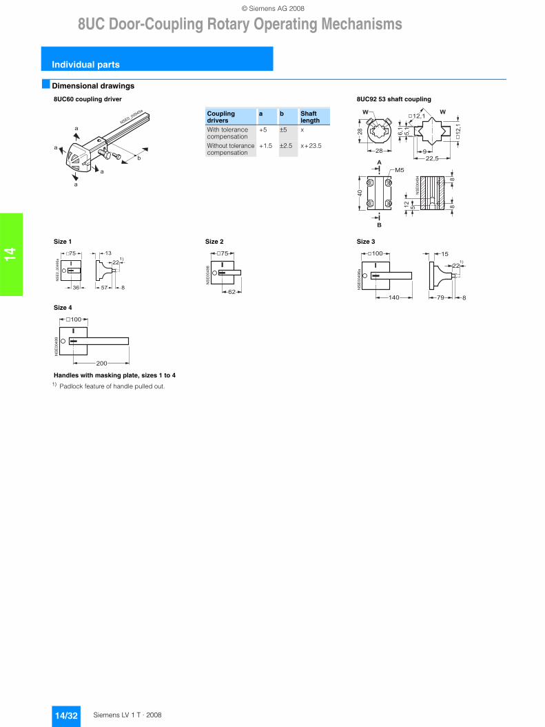
■ Dimensional drawings
1) Padlock feature of handle pulled out.
8UC60 coupling driver 8UC92 53 shaft coupling
Size 1 Size 2 Size 3
Size 4
Handles with masking plate, sizes 1 to 4
�
�
�
�
�� �
� �� �� �� �
�
Coupling drivers
a b Shaft length
With tolerance compensation
+5 ±5 x
Without tolerance compensation
+1.5 ±2.5 x+23.5
��
��
��
��
��
��
�
�
��
���
���
���
�
�
�
���
�
��
����������
�
� � �
� �� �
� �
��
��
��
��
�
�
��
��
��
���
��
�� � �
��
�
��
��
��
��
���
���
© Siemens AG 2008
8UC Door-Coupling Rotary Operating Mechanisms
14/33Siemens LV 1 T · 2008
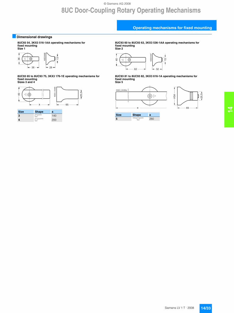
Operating mechanisms for fixed mounting
14
■ Dimensional drawings
8UC93 54, 3KX3 516-1AA operating mechanisms for fixed mounting Size 1
8UC93 60 to 8UC93 63, 3KX3 536-1AA operating mechanisms for fixed mounting Size 2
8UC93 65 to 8UC93 75, 3KX3 176-1E operating mechanisms for fixed mounting Sizes 3 and 4
8UC93 81 to 8UC93 82, 3KX3 616-1A operating mechanisms for fixed mounting Size 5
��
�
��
��
��
�
� �
��
��
��
��
��
�
Size Shape a3 140
4 200
25,5
a
45
NS
E0_
0048
8
65
���
�
� � � � � � � � �
� �
���
Size Shape a5 280
© Siemens AG 2008
4NC Current Transformers for Measuring Purposes
General data
14/34 Siemens LV 1 T · 2008
14
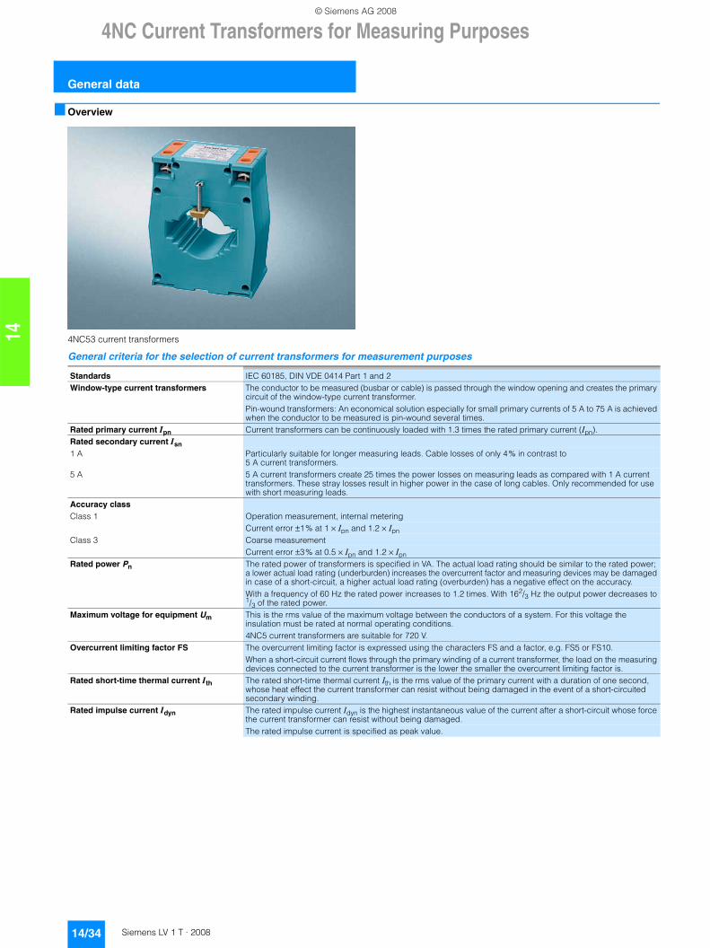
■ Overview
4NC53 current transformers
General criteria for the selection of current transformers for measurement purposes
Standards IEC 60185, DIN VDE 0414 Part 1 and 2Window-type current transformers The conductor to be measured (busbar or cable) is passed through the window opening and creates the primary
circuit of the window-type current transformer.Pin-wound transformers: An economical solution especially for small primary currents of 5 A to 75 A is achieved when the conductor to be measured is pin-wound several times.
Rated primary current Ipn Current transformers can be continuously loaded with 1.3 times the rated primary current (Ipn).Rated secondary current Isn1 A Particularly suitable for longer measuring leads. Cable losses of only 4% in contrast to
5 A current transformers.5 A 5 A current transformers create 25 times the power losses on measuring leads as compared with 1 A current
transformers. These stray losses result in higher power in the case of long cables. Only recommended for use with short measuring leads.
Accuracy classClass 1 Operation measurement, internal metering
Current error ±1% at 1 × Ipn and 1.2 × Ipn Class 3 Coarse measurement
Current error ±3% at 0.5 × Ipn and 1.2 × Ipn Rated power Pn The rated power of transformers is specified in VA. The actual load rating should be similar to the rated power;
a lower actual load rating (underburden) increases the overcurrent factor and measuring devices may be damaged in case of a short-circuit, a higher actual load rating (overburden) has a negative effect on the accuracy.With a frequency of 60 Hz the rated power increases to 1.2 times. With 162/3 Hz the output power decreases to 1/3 of the rated power.
Maximum voltage for equipment Um This is the rms value of the maximum voltage between the conductors of a system. For this voltage the insulation must be rated at normal operating conditions.4NC5 current transformers are suitable for 720 V.
Overcurrent limiting factor FS The overcurrent limiting factor is expressed using the characters FS and a factor, e.g. FS5 or FS10.When a short-circuit current flows through the primary winding of a current transformer, the load on the measuring devices connected to the current transformer is the lower the smaller the overcurrent limiting factor is.
Rated short-time thermal current Ith The rated short-time thermal current Ith is the rms value of the primary current with a duration of one second, whose heat effect the current transformer can resist without being damaged in the event of a short-circuited secondary winding.
Rated impulse current Idyn The rated impulse current Idyn is the highest instantaneous value of the current after a short-circuit whose force the current transformer can resist without being damaged.The rated impulse current is specified as peak value.
© Siemens AG 2008
4NC Current Transformers for Measuring Purposes
14/35Siemens LV 1 T · 2008
General data
14
■ Technical specifications
Standards IEC 60185, DIN VDE 0414 Part 1 and 2Rated primary current Ipn A 50 ... 1500,
5 ... 75, for use as pin-wound transformer for low currentsRated secondary current Isn A 1 or 5Maximum voltage for equipment Um V 720Frequency Hz 50 ... 60Rated overcurrent limiting factor FS FS5 (DIN VDE/IEC)Max. uninterrupted current 1.2 × IpnRated short-time thermal current Ith 60 × IpnRated impulse current Idyn 2.5 × Ith or 150 × IpnAccuracy class 1 (3)Ambient temperature °C +55 at 1.0 × Ipn
°C +40 at 1.2 × Ipn°C -10 minimum value
Max. busbar temperature °C +120Molded-plastic class E (max. 120 °C continuously)Insulation Thermoplast enclosure, halogen-freeTest voltage kV 3 ACSecondary terminals Double terminals using M4 captive screws,
finger-safe to DIN VDE 0106 Part 100Solid mm2 2 × (2.5 ... 6)
Two-wire mm2 2 × (1.5 ... 4)
Terminals with same polarity primary ➝ secondaryK/P1 ➝ k/S1 (DIN VDE/IEC)L/P2 ➝ l/S2 (DIN VDE/IEC)
Mounting Either busbar or foot mounting
© Siemens AG 2008
4NC Current Transformers for Measuring Purposes
Classes 1 and 3, from 50 A to 1500 A
14/36 Siemens LV 1 T · 2008
14
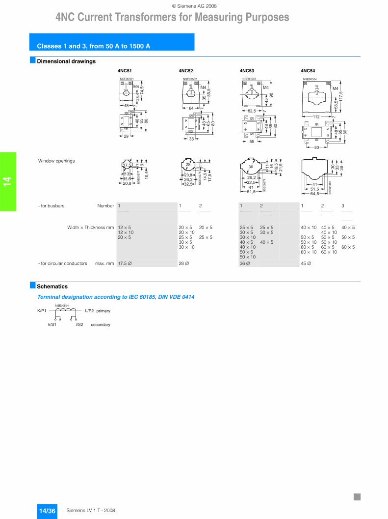
■ Dimensional drawings
■ Schematics
Terminal designation according to IEC 60185, DIN VDE 0414
4NC51 4NC52 4NC53 4NC54
Window openings
��
��
��
���
���
������
� ��
��
���
��
��
��
����
������
��
��
��
���
����
��
�
��
������
��
��
��
���
���
��
��
���
��
��
������
��
��
��
���
� ������
���� �
�
��
��
����
����
��������
����
�
�
��
��
����
��
������
�� ��
��
� ��
����
����������
���� �
�
��
�
��
��
��
���������� �
���
��
- for busbars Number 1 1 2 1 2 1 2 3––––– ––––– –––––
–––––––––– –––––
–––––––––– –––––
––––––––––––––––––––
Width × Thickness mm 12 × 512 × 1020 × 5
20 × 520 × 1025 × 530 × 530 × 10
20 × 5
25 × 5
25 × 530 × 530 × 1040 × 540 × 1050 × 550 × 10
25 × 530 × 5
40 × 5
40 × 10
50 × 550 × 1060 × 560 × 10
40 × 540 × 1050 × 550 × 1060 × 560 × 10
40 × 5
50 × 5
60 × 5
- for circular conductors max. mm 17.5 ∅ 28 ∅ 36 ∅ 45 ∅
K/P1 L/P2
k/S1 � /S2
NSE00594
primary
secondary
© Siemens AG 2008