Embed Size (px)
Citation preview
1-4120-EN
SKF Dry Lubrication Systems for conveyors
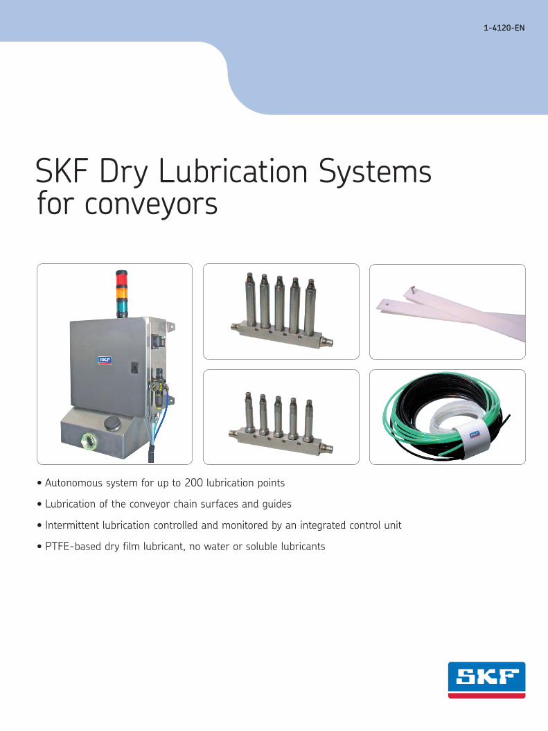
• Autonomous system for up to 200 lubrication points
• Lubrication of the conveyor chain surfaces and guides
• Intermittent lubrication controlled and monitored by an integrated control unit
• PTFE-based dry film lubricant, no water or soluble lubricants
SKF Dry Lubrication Systems for conveyors
2 1-4120-EN
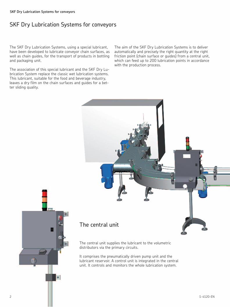
The central unit
The central unit supplies the lubricant to the volumetric distributors via the primary circuits.
It comprises the pneumatically driven pump unit and the lubricant reservoir. A control unit is integrated in the central unit. It controls and monitors the whole lubrication system.
The SKF Dry Lubrication Systems, using a special lubricant, have been developed to lubricate conveyor chain surfaces, as well as chain guides, for the transport of products in bottling and packaging unit.
The association of this special lubricant and the SKF Dry Lu-brication System replace the classic wet lubrication systems. This lubricant, suitable for the food and beverage industry, leaves a dry film on the chain surfaces and guides for a bet-ter sliding quality.
The aim of the SKF Dry Lubrication Systems is to deliver auto matically and precisely the right quantity at the right friction point (chain surface or guides) from a central unit, which can feed up to 200 lubrication points in accordance with the production process.
SKF Dry Lubrication Systems for conveyors
SKF Dry Lubrication Systems for conveyors
31-4120-EN
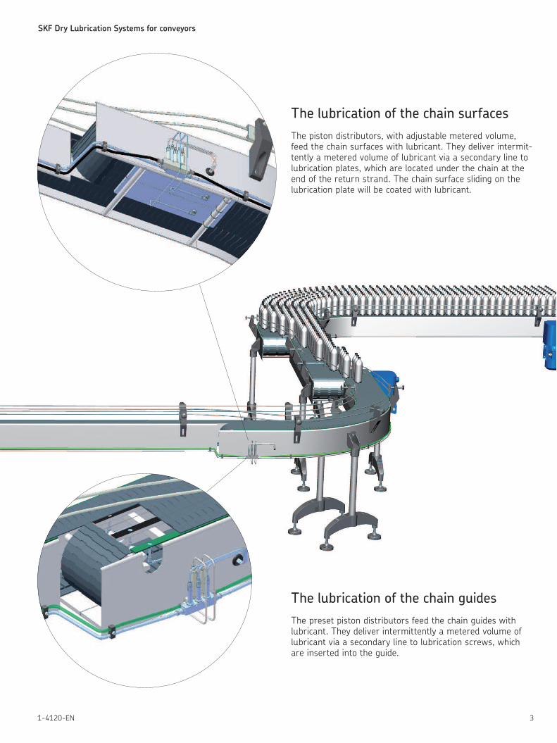
The lubrication of the chain guides
The preset piston distributors feed the chain guides with lubricant. They deliver intermittently a metered volume of lubricant via a secondary line to lubrication screws, which are inserted into the guide.
The lubrication of the chain surfaces
The piston distributors, with adjustable metered volume, feed the chain surfaces with lubricant. They deliver intermit-tently a metered volume of lubricant via a secondary line to lubrication plates, which are located under the chain at the end of the return strand. The chain surface sliding on the lubrication plate will be coated with lubricant.
SKF Dry Lubrication Systems for conveyors
4 1-4120-EN
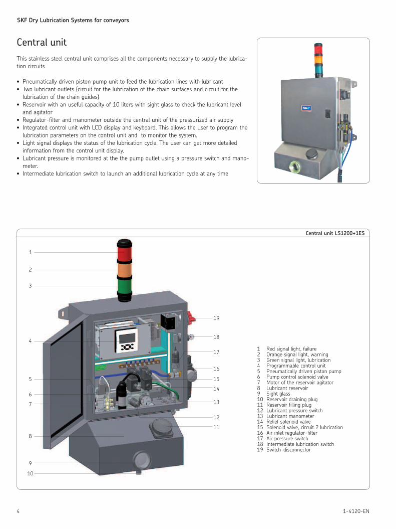
Central unit
This stainless steel central unit comprises all the components necessary to supply the lubrica-
tion circuits
• Pneumatically driven piston pump unit to feed the lubrication lines with lubricant
• Two lubricant outlets (circuit for the lubrication of the chain surfaces and circuit for the
lubrication of the chain guides)
• Reservoir with an useful capacity of 10 liters with sight glass to check the lubricant level
and agitator
• Regulator-filter and manometer outside the central unit of the pressurized air supply
• Integrated control unit with LCD display and keyboard. This allows the user to program the
lubrication parameters on the control unit and to monitor the system.
• Light signal displays the status of the lubrication cycle. The user can get more detailed
information from the control unit display.
• Lubricant pressure is monitored at the the pump outlet using a pressure switch and mano-
meter.
• Intermediate lubrication switch to launch an additional lubrication cycle at any time
Central unit LS1200+1ES
1 Red signal light, failure2 Orange signal light, warning3 Green signal light, lubrication4 Programmable control unit5 Pneumatically driven piston pump6 Pump control solenoid valve7 Motor of the reservoir agitator8 Lubricant reservoir9 Sight glass10 Reservoir draining plug11 Reservoir filling plug12 Lubricant pressure switch13 Lubricant manometer14 Relief solenoid valve15 Solenoid valve, circuit 2 lubrication16 Air inlet regulator-filter17 Air pressure switch18 Intermediate lubrication switch19 Switch-disconnector
1
2
3
4
5
6
7
8
9
10
11
12
13
14
15
16
17
18
1
19
SKF Dry Lubrication Systems for conveyors
51-4120-EN
23
2
83
9
315
446
507
32
52
42
406
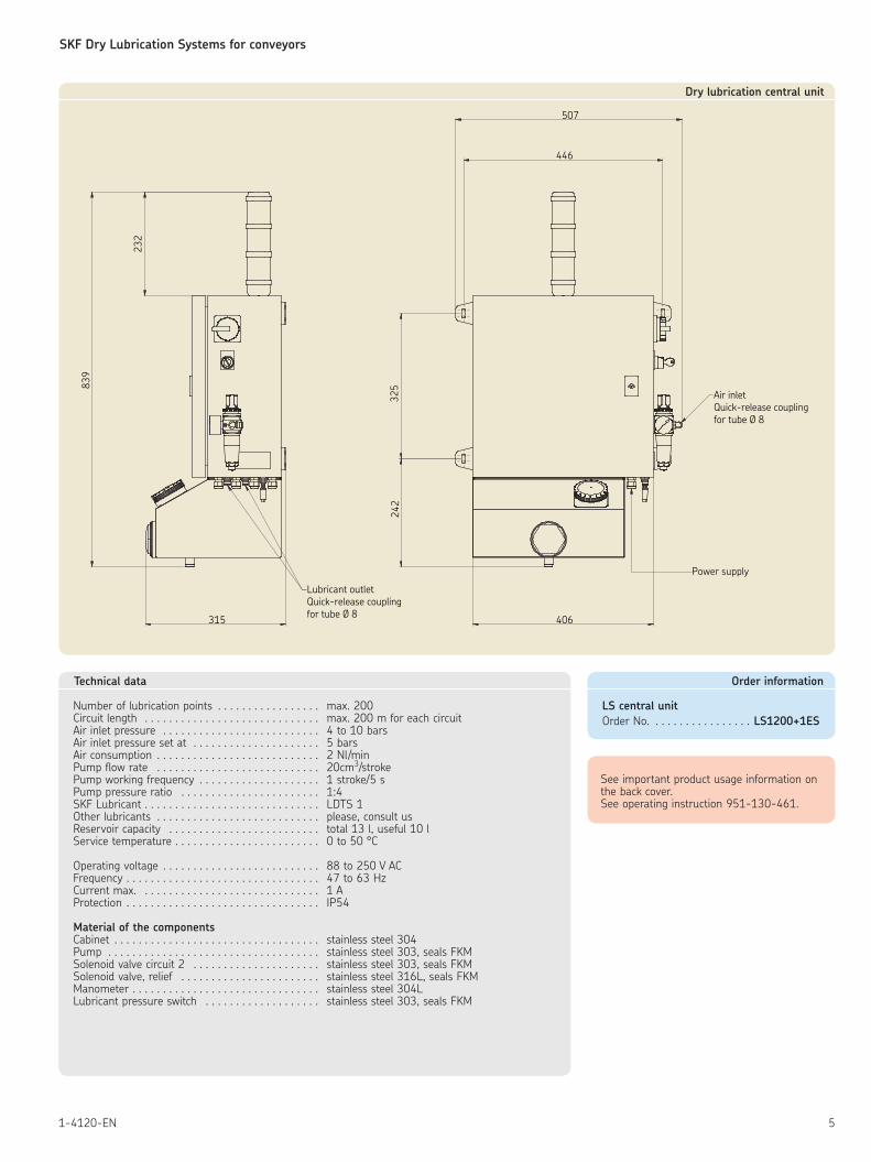
Air inletQuick-release couplingfor tube Ø 8
Power supply
Lubricant outletQuick-release couplingfor tube Ø 8
Dry lubrication central unit
Technical data
Number of lubrication points . . . . . . . . . . . . . . . . . max. 200Circuit length . . . . . . . . . . . . . . . . . . . . . . . . . . . . . max. 200 m for each circuitAir inlet pressure . . . . . . . . . . . . . . . . . . . . . . . . . . 4 to 10 barsAir inlet pressure set at . . . . . . . . . . . . . . . . . . . . . 5 barsAir consumption . . . . . . . . . . . . . . . . . . . . . . . . . . . 2 Nl/minPump flow rate . . . . . . . . . . . . . . . . . . . . . . . . . . . 20cm3/strokePump working frequency . . . . . . . . . . . . . . . . . . . . 1 stroke/5 sPump pressure ratio . . . . . . . . . . . . . . . . . . . . . . . 1:4SKF Lubricant . . . . . . . . . . . . . . . . . . . . . . . . . . . . . LDTS 1Other lubricants . . . . . . . . . . . . . . . . . . . . . . . . . . . please, consult usReservoir capacity . . . . . . . . . . . . . . . . . . . . . . . . . total 13 l, useful 10 lService temperature . . . . . . . . . . . . . . . . . . . . . . . . 0 to 50 °C
Operating voltage . . . . . . . . . . . . . . . . . . . . . . . . . . 88 to 250 V ACFrequency . . . . . . . . . . . . . . . . . . . . . . . . . . . . . . . . 47 to 63 HzCurrent max. . . . . . . . . . . . . . . . . . . . . . . . . . . . . . 1 AProtection . . . . . . . . . . . . . . . . . . . . . . . . . . . . . . . . IP54
Material of the componentsCabinet . . . . . . . . . . . . . . . . . . . . . . . . . . . . . . . . . . stainless steel 304Pump . . . . . . . . . . . . . . . . . . . . . . . . . . . . . . . . . . . stainless steel 303, seals FKMSolenoid valve circuit 2 . . . . . . . . . . . . . . . . . . . . . stainless steel 303, seals FKMSolenoid valve, relief . . . . . . . . . . . . . . . . . . . . . . . stainless steel 316L, seals FKMManometer . . . . . . . . . . . . . . . . . . . . . . . . . . . . . . . stainless steel 304LLubricant pressure switch . . . . . . . . . . . . . . . . . . . stainless steel 303, seals FKM
Order information
LS central unit
Order No. . . . . . . . . . . . . . . . . LS1200+1ES
See important product usage information on the back cover.See operating instruction 951-130-461.
SKF Dry Lubrication Systems for conveyors
6 1-4120-EN
BV
BO
Y3
SPO
AG
NV
C2 C1
SL
Y2
SPA
MA1FI
R1
Y1
MA2
LD1 LD2
MA2
MA2
MA2
MA2
Central unit
Motor-driven pump
LS22
LS21
P
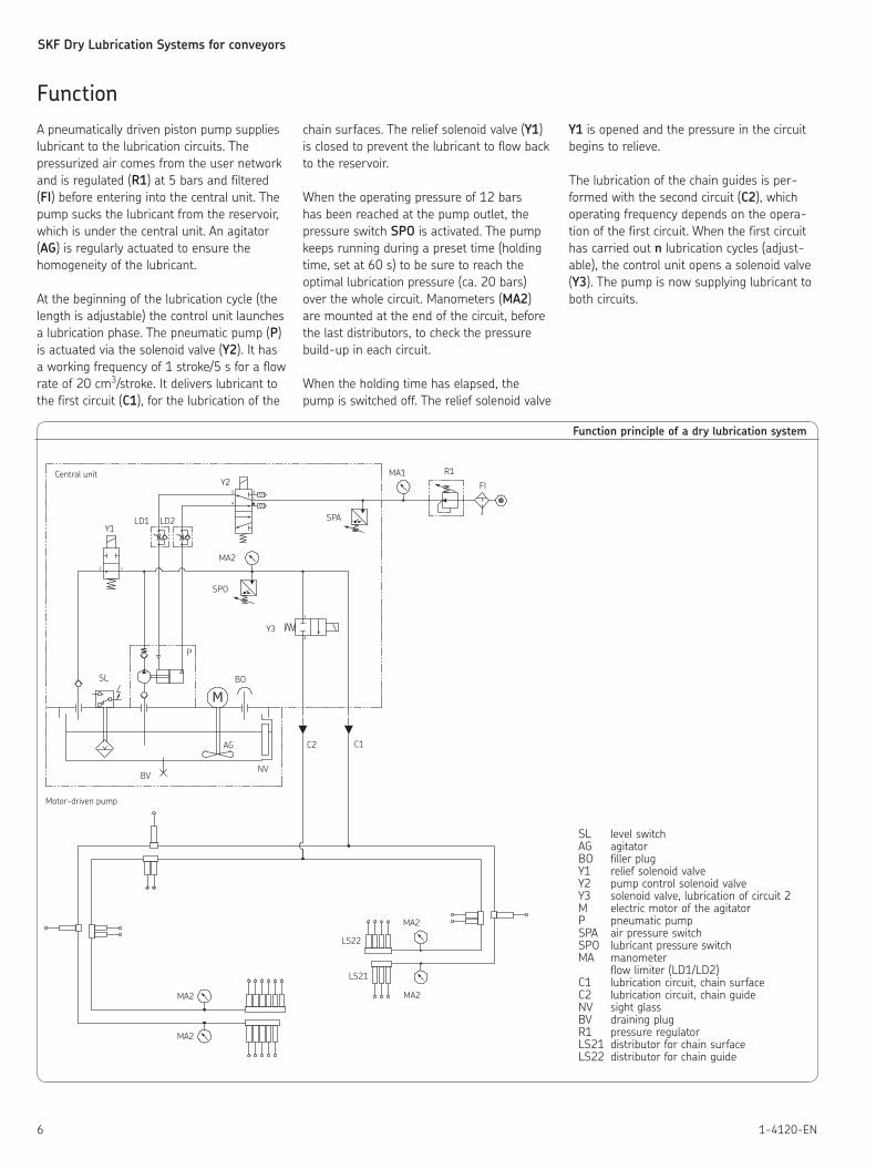
Function principle of a dry lubrication system
SL level switchAG agitatorBO filler plugY1 relief solenoid valveY2 pump control solenoid valveY3 solenoid valve, lubrication of circuit 2M electric motor of the agitatorP pneumatic pumpSPA air pressure switchSPO lubricant pressure switchMA manometer flow limiter (LD1/LD2)C1 lubrication circuit, chain surfaceC2 lubrication circuit, chain guideNV sight glassBV draining plugR1 pressure regulatorLS21 distributor for chain surfaceLS22 distributor for chain guide
Function
A pneumatically driven piston pump supplies
lubricant to the lubrication circuits. The
pressurized air comes from the user network
and is regulated (R1) at 5 bars and filtered
(FI) before entering into the central unit. The
pump sucks the lubricant from the reservoir,
which is under the central unit. An agitator
(AG) is regularly actuated to ensure the
homogeneity of the lubricant.
At the beginning of the lubrication cycle (the
length is adjustable) the control unit launches
a lubrication phase. The pneumatic pump (P)
is actuated via the solenoid valve (Y2). It has
a working frequency of 1 stroke/5 s for a flow
rate of 20 cm3/stroke. It delivers lubricant to
the first circuit (C1), for the lubrication of the
chain surfaces. The relief solenoid valve (Y1)
is closed to prevent the lubricant to flow back
to the reservoir.
When the operating pressure of 12 bars
has been reached at the pump outlet, the
pressure switch SPO is activated. The pump
keeps running during a preset time (holding
time, set at 60 s) to be sure to reach the
optimal lubrication pressure (ca. 20 bars)
over the whole circuit. Manometers (MA2)
are mounted at the end of the circuit, before
the last distributors, to check the pressure
build-up in each circuit.
When the holding time has elapsed, the
pump is switched off. The relief solenoid valve
Y1 is opened and the pressure in the circuit
begins to relieve.
The lubrication of the chain guides is per-
formed with the second circuit (C2), which
operating frequency depends on the opera-
tion of the first circuit. When the first circuit
has carried out n lubrication cycles (adjust-
able), the control unit opens a solenoid valve
(Y3). The pump is now supplying lubricant to
both circuits.
SKF Dry Lubrication Systems for conveyors
71-4120-EN
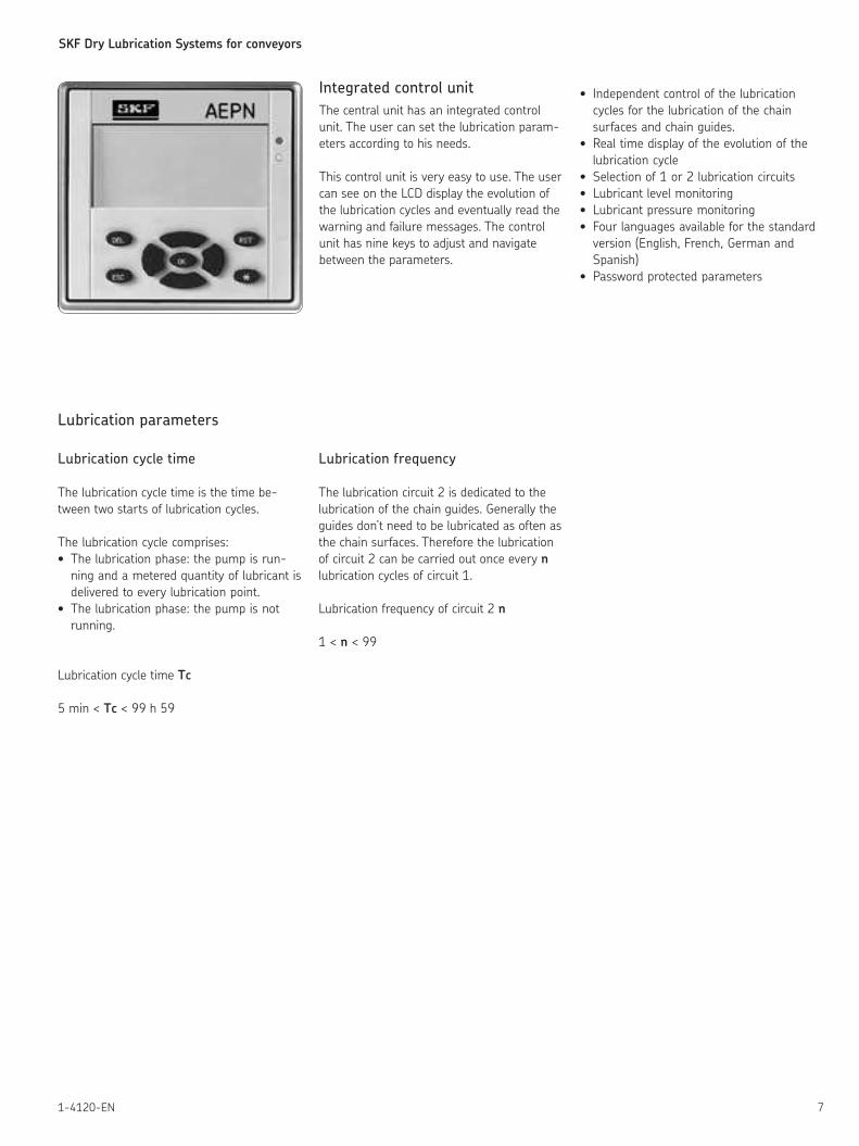
Integrated control unit
The central unit has an integrated control
unit. The user can set the lubrication param-
eters according to his needs.
This control unit is very easy to use. The user
can see on the LCD display the evolution of
the lubrication cycles and eventually read the
warning and failure messages. The control
unit has nine keys to adjust and navigate
between the parameters.
• Independent control of the lubrication
cycles for the lubrication of the chain
surfaces and chain guides.
• Real time display of the evolution of the
lubrication cycle
• Selection of 1 or 2 lubrication circuits
• Lubricant level monitoring
• Lubricant pressure monitoring
• Four languages available for the standard
version (English, French, German and
Spanish)
• Password protected parameters
Lubrication parameters
Lubrication cycle time
The lubrication cycle time is the time be-
tween two starts of lubrication cycles.
The lubrication cycle comprises:
• The lubrication phase: the pump is run-
ning and a metered quantity of lubricant is
delivered to every lubrication point.
• The lubrication phase: the pump is not
running.
Lubrication cycle time Tc
5 min < Tc < 99 h 59
Lubrication frequency
The lubrication circuit 2 is dedicated to the
lubrication of the chain guides. Generally the
guides don’t need to be lubricated as often as
the chain surfaces. Therefore the lubrication
of circuit 2 can be carried out once every n
lubrication cycles of circuit 1.
Lubrication frequency of circuit 2 n
1 < n < 99
SKF Dry Lubrication Systems for conveyors
8 1-4120-EN
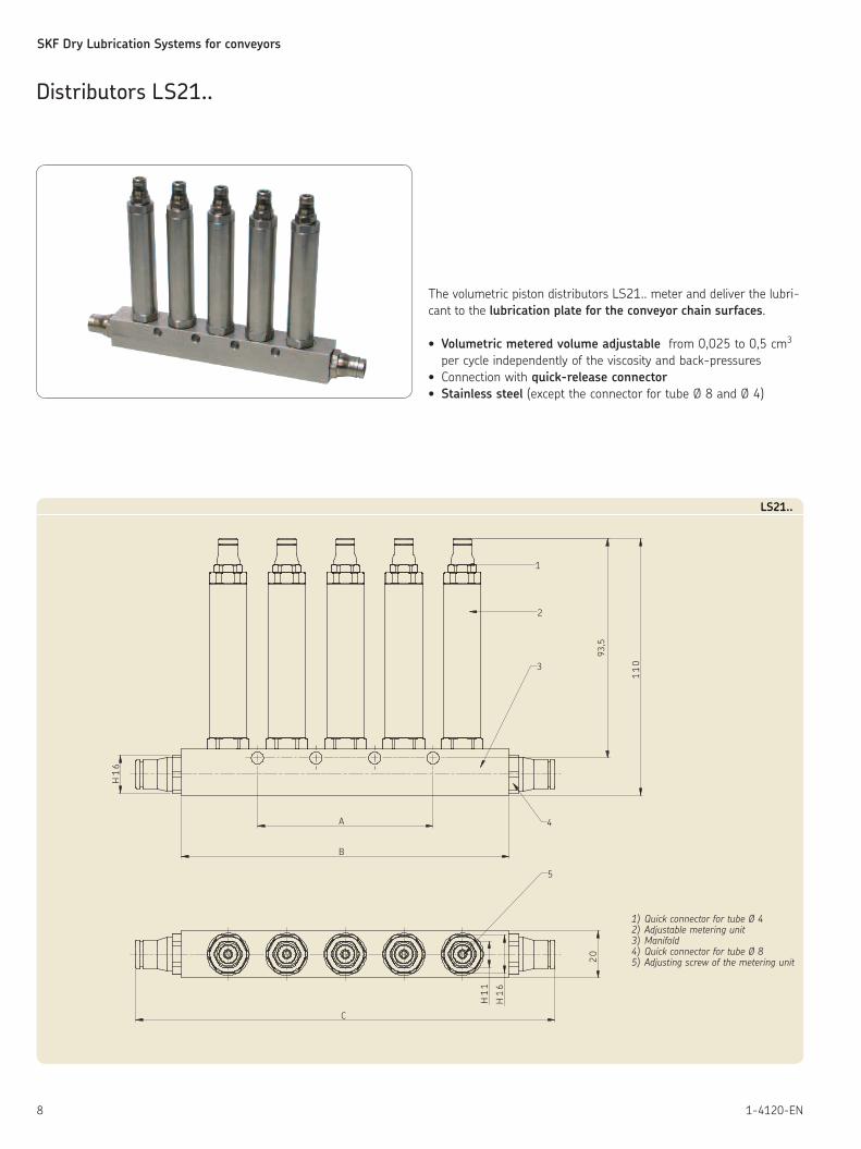
The volumetric piston distributors LS21.. meter and deliver the lubri-
cant to the lubrication plate for the conveyor chain surfaces.
• Volumetric metered volume adjustable from 0,025 to 0,5 cm3
per cycle independently of the viscosity and back-pressures
• Connection with quick-release connector
• Stainless steel (except the connector for tube Ø 8 and Ø 4)
11
0
93,5
1
2
3
4
5
20
16
H
11
H
16
H
A
B
C
LS21..
1) Quick connector for tube Ø 42) Adjustable metering unit3) Manifold4) Quick connector for tube Ø 85) Adjusting screw of the metering unit
Distributors LS21..
SKF Dry Lubrication Systems for conveyors
91-4120-EN
Order information
Adjustable distributor
Order No. Outlet(s) Size A Size B Size C
LS2110 1 - 50 89
LS2120 2 - 65 104
LS2130 3 25 90 129
LS2140 4 50 115 154
LS2150 5 75 140 179
Technical data
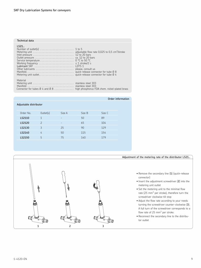
LS21..Number of outlet(s) . . . . . . . . . . . . . . . . . . . . . . . . 1 to 5Metering unit . . . . . . . . . . . . . . . . . . . . . . . . . . . . . adjustable flow rate 0,025 to 0,5 cm3/strokeInlet pressure . . . . . . . . . . . . . . . . . . . . . . . . . . . . . 12 to 20 barsOutlet pressure . . . . . . . . . . . . . . . . . . . . . . . . . . . . ca. 12 to 20 barsService temperature . . . . . . . . . . . . . . . . . . . . . . . . 0 °C to 50 °CWorking frequency . . . . . . . . . . . . . . . . . . . . . . . . . ≤ 1 stroke/2 sLubricant SKF . . . . . . . . . . . . . . . . . . . . . . . . . . . . LDTS 1Other lubricants . . . . . . . . . . . . . . . . . . . . . . . . . . . please, consult usManifold. . . . . . . . . . . . . . . . . . . . . . . . . . . . . . . . . . quick-release connector for tube Ø 8Metering unit outlet. . . . . . . . . . . . . . . . . . . . . . . . . quick-release connector for tube Ø 4
MaterialMetering unit . . . . . . . . . . . . . . . . . . . . . . . . . . . . . stainless steel 303Manifold . . . . . . . . . . . . . . . . . . . . . . . . . . . . . . . . . stainless steel 303Connector for tubes Ø 4 and Ø 8 . . . . . . . . . . . . . . high phosphorus FDA chem. nickel-plated brass
Adjustment of the metering rate of the distributor LS21..
• Remove the secondary line (1) (quick-release
connector)
• Insert the adjustment screwdriver (2) into the
metering unit outlet
• Set the metering unit to the minimal flow
rate (25 mm3 per stroke), therefore turn the
screwdriver clockwise till stop
• Adjust the flow rate according to your needs
turning the screwdriver counter-clockwise (3).
A full turn of the screwdriver corresponds to a
flow rate of 25 mm3 per stroke.
• Reconnect the secondary line to the distribu-
tor outlet
2 31
SKF Dry Lubrication Systems for conveyors
10 1-4120-EN
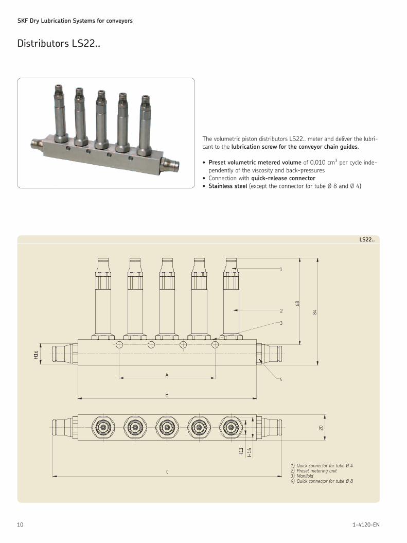
The volumetric piston distributors LS22.. meter and deliver the lubri-
cant to the lubrication screw for the conveyor chain guides.
• Preset volumetric metered volume of 0,010 cm3 per cycle inde-
pendently of the viscosity and back-pressures
• Connection with quick-release connector
• Stainless steel (except the connector for tube Ø 8 and Ø 4)
84
68
�
�
�
���
���
20
1
2
3
4
���
LS22..
1) Quick connector for tube Ø 42) Preset metering unit3) Manifold4) Quick connector for tube Ø 8
Distributors LS22..
SKF Dry Lubrication Systems for conveyors
111-4120-EN
Order information
Volumetric distributor LS22..
Order No. Outlet(s) Size A Size B Size C
LS2210 1 - 50 89
LS2220 2 - 65 104
LS2230 3 25 90 129
LS2240 4 50 115 154
LS2250 5 75 140 179
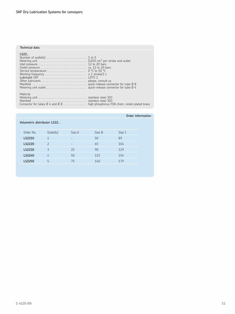
Technical data
LS22..Number of outlet(s) . . . . . . . . . . . . . . . . . . . . . . . . 1 to 5Metering unit . . . . . . . . . . . . . . . . . . . . . . . . . . . . . 0,010 cm3 per stroke and outletInlet pressure . . . . . . . . . . . . . . . . . . . . . . . . . . . . . 12 to 20 barsOutlet pressure . . . . . . . . . . . . . . . . . . . . . . . . . . . . ca. 12 to 20 barsService temperature . . . . . . . . . . . . . . . . . . . . . . . . 0 °C to 50 °CWorking frequency . . . . . . . . . . . . . . . . . . . . . . . . . ≤ 1 stroke/2 sLubricant SKF . . . . . . . . . . . . . . . . . . . . . . . . . . . . LDTS 1Other lubricants . . . . . . . . . . . . . . . . . . . . . . . . . . . please, consult usManifold. . . . . . . . . . . . . . . . . . . . . . . . . . . . . . . . . . quick-release connector for tube Ø 8Metering unit outlet. . . . . . . . . . . . . . . . . . . . . . . . . quick-release connector for tube Ø 4
MaterialMetering unit. . . . . . . . . . . . . . . . . . . . . . . . . . . . . . stainless steel 303Manifold . . . . . . . . . . . . . . . . . . . . . . . . . . . . . . . . . stainless steel 303Connector for tubes Ø 4 and Ø 8 . . . . . . . . . . . . . . high phosphorus FDA chem. nickel-plated brass
SKF Dry Lubrication Systems for conveyors
12 1-4120-EN
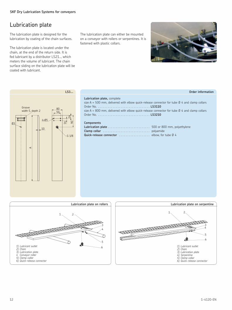
Lubrication plate
The lubrication plate is designed for the
lubrication by coating of the chain surfaces.
The lubrication plate is located under the
chain, at the end of the return side. It is
fed lubricant by a distributor LS21.., which
meters the volume of lubricant. The chain
surface sliding on the lubrication plate will be
coated with lubricant.
A
10
80
16
2490
4×Ø5
G 1/8
Groove width 5, depth 2
Ø3
50
LS3...
2
3
4
6
5
1
Lubrication plate on rollers
21
34
5
6
Lubrication plate on serpentine
Order information
Lubrication plate, complete
size A = 500 mm, delivered with elbow quick-release connector for tube Ø 4 and clamp collars
Order No. . . . . . . . . . . . . . . . . . . . . . . . . . . . . . . . . LS3110
size A = 800 mm, delivered with elbow quick-release connector for tube Ø 4 and clamp collars
Order No. . . . . . . . . . . . . . . . . . . . . . . . . . . . . . . . . LS3210
Components
Lubrication plate . . . . . . . . . . . . . . . . . . . . . . . . . . 500 or 800 mm, polyethylene
Clamp collar . . . . . . . . . . . . . . . . . . . . . . . . . . . . . polyamide
Quick-release connector . . . . . . . . . . . . . . . . . . . elbow, for tube Ø 4
1) Lubricant outlet2) Chain3) Lubrication plate4 Conveyor roller5) Clamp collar 6) Quick-release connector
1) Lubricant outlet2) Chain3) Lubrication plate4) Serpentine5) Clamp collar 6) Quick-release connector
The lubrication plate can either be mounted
on a conveyor with rollers or serpentines. It is
fastened with plastic collars.
SKF Dry Lubrication Systems for conveyors
131-4120-EN
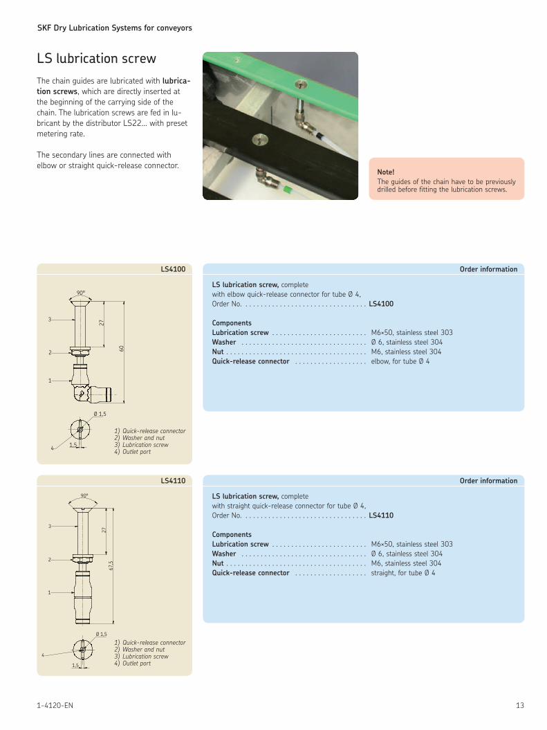
LS lubrication screw
The chain guides are lubricated with lubrica-
tion screws, which are directly inserted at
the beginning of the carrying side of the
chain. The lubrication screws are fed in lu-
bricant by the distributor LS22... with preset
metering rate.
The secondary lines are connected with
elbow or straight quick-release connector.
Order information
LS lubrication screw, complete
with straight quick-release connector for tube Ø 4,
Order No. . . . . . . . . . . . . . . . . . . . . . . . . . . . . . . . . LS4110
Components
Lubrication screw . . . . . . . . . . . . . . . . . . . . . . . . . M6×50, stainless steel 303
Washer . . . . . . . . . . . . . . . . . . . . . . . . . . . . . . . . . Ø 6, stainless steel 304
Nut . . . . . . . . . . . . . . . . . . . . . . . . . . . . . . . . . . . . . M6, stainless steel 304
Quick-release connector . . . . . . . . . . . . . . . . . . . straight, for tube Ø 4
Ø 1,5
1,5
4
3
90°
27
67
,5
2
1
LS4110
1) Quick-release connector2) Washer and nut3) Lubrication screw4) Outlet port
Order information
LS lubrication screw, complete
with elbow quick-release connector for tube Ø 4,
Order No. . . . . . . . . . . . . . . . . . . . . . . . . . . . . . . . . LS4100
Components
Lubrication screw . . . . . . . . . . . . . . . . . . . . . . . . . M6×50, stainless steel 303
Washer . . . . . . . . . . . . . . . . . . . . . . . . . . . . . . . . . Ø 6, stainless steel 304
Nut . . . . . . . . . . . . . . . . . . . . . . . . . . . . . . . . . . . . . M6, stainless steel 304
Quick-release connector . . . . . . . . . . . . . . . . . . . elbow, for tube Ø 4
Ø 1,5
1,54
3
27
2 60
1
90°
LS4100
1) Quick-release connector2) Washer and nut3) Lubrication screw4) Outlet port
Note!
The guides of the chain have to be previously drilled before fitting the lubrication screws.
SKF Dry Lubrication Systems for conveyors
14 1-4120-EN
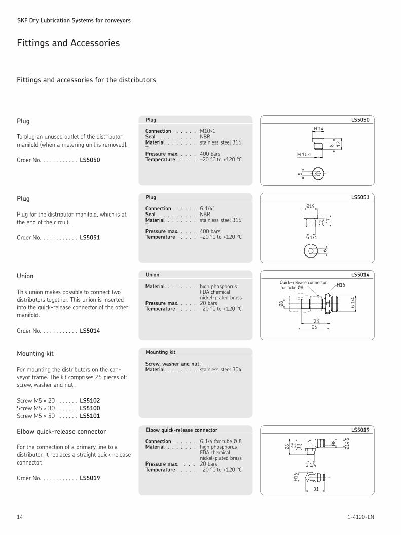
Fittings and Accessories
Fittings and accessories for the distributors
Plug
To plug an unused outlet of the distributor
manifold (when a metering unit is removed).
Order No. . . . . . . . . . . . LS5050
Ø19
12 17
6
G 1/4
LS5051Plug
Connection . . . . . G 1/4"Seal . . . . . . . . . NBRMaterial . . . . . . . stainless steel 316 TiPressure max. . . . . 400 barsTemperature . . . . –20 °C to +120 °C
Union
This union makes possible to connect two
distributors together. This union is inserted
into the quick-release connector of the other
manifold.
Order No. . . . . . . . . . . . LS5014
Quick-release connectorfor tube Ø8
26
Ø8 G 1/
4
23
H16
LS5014Union
Material . . . . . . . high phosphorus FDA chemical nickel-plated brassPressure max. . . . . 20 barsTemperature . . . . –20 °C to +120 °C
Mounting kit
For mounting the distributors on the con-
veyor frame. The kit comprises 25 pieces of:
screw, washer and nut.
Screw M5 × 20 . . . . . . LS5102
Screw M5 × 30 . . . . . . LS5100
Screw M5 × 50 . . . . . . LS5101
Mounting kit
Screw, washer and nut.Material . . . . . . . stainless steel 304
Plug
Plug for the distributor manifold, which is at
the end of the circuit.
Order No. . . . . . . . . . . . LS5051
Ø 14
5
8 12
M 10×1
LS5050Plug
Connection . . . . . M10×1 Seal . . . . . . . . . NBRMaterial . . . . . . . stainless steel 316 TiPressure max. . . . . 400 barsTemperature . . . . –20 °C to +120 °C
G 1/4
H16
Ø82026
31
Ø14,
5
13
LS5019Elbow quick-release connector
For the connection of a primary line to a
distributor. It replaces a straight quick-release
connector.
Order No. . . . . . . . . . . . LS5019
Elbow quick-release connector
Connection . . . . . G 1/4 for tube Ø 8Material . . . . . . . high phosphorus FDA chemical nickel-plated brassPressure max. . . . 20 barsTemperature . . . . –20 °C to +120 °C
SKF Dry Lubrication Systems for conveyors
151-4120-EN
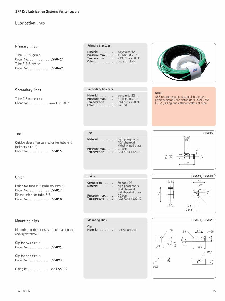
Lubrication lines
Primary lines
Tube 5,5×8, green
Order No. . . . . . . . . . . . LS5041*
Tube 5,5×8, white
Order No. . . . . . . . . . . . LS5042*
Primary line tube
Material . . . . . . . polyamide 12Pressure max. . . . . 49 bars at 20 °CTemperature . . . . –10 °C to +50 °CColor . . . . . . . . . green or black
Secondary lines
Tube 2,5×4, neutral
Order No. . . . . . . . . . . . +++ LS5040*
Secondary line tube
Material . . . . . . . polyamide 12Pressure max. . . . . 30 bars at 20 °CTemperature . . . . –10 °C to +50 °CColor . . . . . . . . . neutral
Note!
SKF recommends to distinguish the two primary circuits (for distributors LS21.. and LS22..) using two different colors of tube.
Tee
Quick-release Tee connector for tube Ø 8
(primary circuit)
Order No. . . . . . . . . . . . LS5015
Ø8
47
23,7
Ø14,5
Ø14,
5
Ø8Ø8
LS5015Tee
Material . . . . . . . high phosphorus FDA chemical nickel-plated brassPressure max. . . . . 20 barsTemperature . . . . –20 °C to +120 °C
21,5
Ø8
Ø6,5
62
12,5
12
Ø6,5
30,5
26
17,5 Ø8
1212
,5
Ø8
LS5093, LS5091 Mounting clips
Mounting of the primary circuits along the
conveyor frame.
Clip for two circuit
Order No. . . . . . . . . . . . LS5091
Clip for one circuit
Order No. . . . . . . . . . . . LS5093
Fixing kit . . . . . . . . . . . . see LS5102
Mounting clips
ClipMaterial . . . . . . . polypropylene
Union
Union for tube Ø 8 (primary circuit)
Order No. . . . . . . . . . . . LS5017
Elbow union for tube Ø 8,
Order No. . . . . . . . . . . . LS5018
Union
Connection . . . . . for tube Ø8Material . . . . . . . high phosphorus FDA chemical nickel-plated brassPressure max. . . . . 20 barsTemperature . . . . –20 °C to +120 °C
3124
Ø8Ø8
Ø14,5
37,5
Ø8Ø14,5
LS5017, LS5018
SKF Dry Lubrication Systems for conveyors
16 1-4120-EN
Identification rings
Rings to identify the secondary lines.
Bag: 100 rings 5 colors (orange, red, green,
black, yellow)
Order No. . . . . . . . . . . . LS5094
Plastic collars
For primary and secondary lines.
100 pieces in one bag.
Order No. . . . . . . . . . . . LS5090
Tube bushing
To let the secondary lines through the con-
veyor frame
Tube bushing for 1 to 8 tubes
Order No. . . . . . . . . . . . LS5092
Tube cutter
For Rilsan tube Ø 4 to Ø 12
Order No. . . . . . . . . . . . LS5096
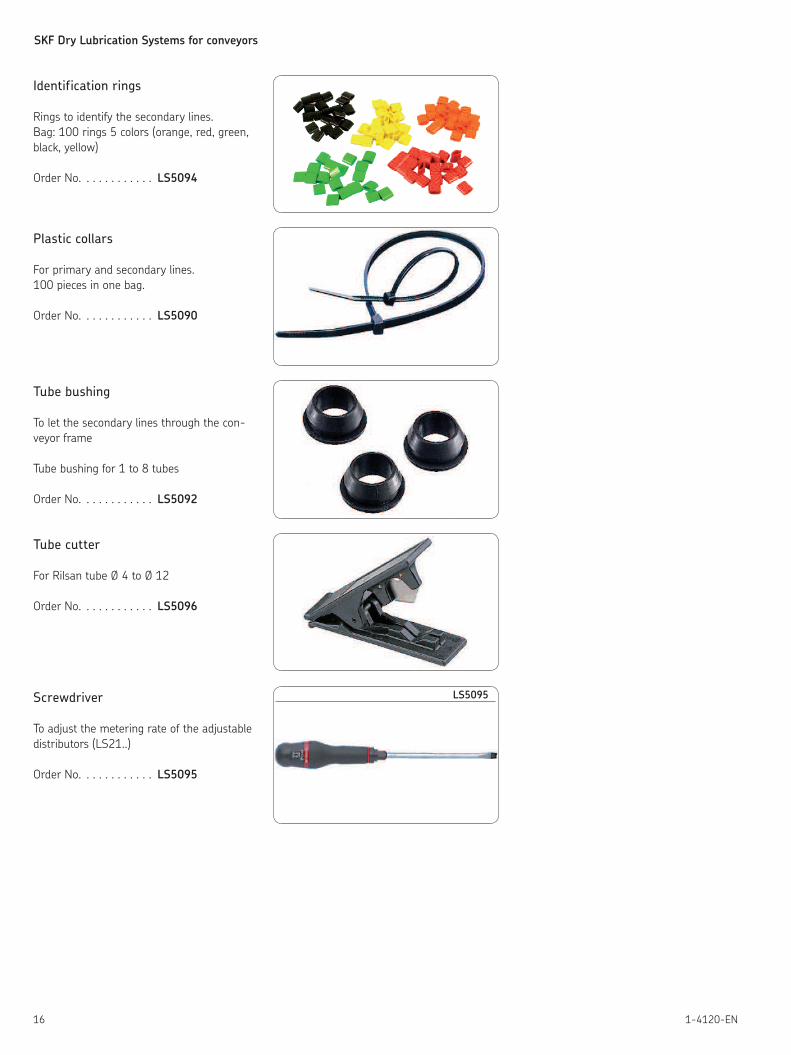
Screwdriver
To adjust the metering rate of the adjustable
distributors (LS21..)
Order No. . . . . . . . . . . . LS5095
LS5095
SKF Dry Lubrication Systems for conveyors
171-4120-EN
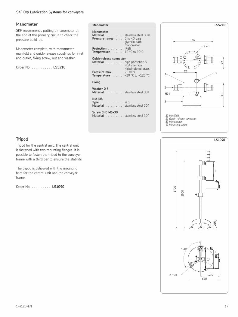
3
2
1 4
53,5
89
Ø 40
52
H14
27
LS5210
1) Manifold2) Quick-release connector3) Manometer4) Mounting screw
Manometer
SKF recommends putting a manometer at
the end of the primary circuit to check the
pressure build-up.
Manometer complete, with manometer,
manifold and quick-release couplings for inlet
and outlet, fixing screw, nut and washer.
Order No. . . . . . . . . . . . LS5210
Manometer
ManometerMaterial . . . . . . . stainless steel 304LPressure range . . . 0 to 40 bars glycerin bath manometerProtection . . . . . . IP65Temperature . . . . 10 °C to 90°C
Quick-release connectorMaterial . . . . . . . high phosphorus FDA chemical nickel-plated brass Pressure max. 20 barsTemperature . . . . –20 °C to +120 °C
Fixing
Washer Ø 5Material . . . . . . . stainless steel 304
Nut M5Type . . . . . . . . . Ø 5Material . . . . . . . stainless steel 304
Screw CHC M5×30Material . . . . . . . stainless steel 304
Ø 550 415
17
00
15
00
690
21
0
120°
LS1090Tripod
Tripod for the central unit. The central unit
is fastened with two mounting flanges. It is
possible to fasten the tripod to the conveyor
frame with a third bar to ensure the stability.
The tripod is delivered with the mounting
bars for the central unit and the conveyor
frame.
Order No. . . . . . . . . . . LS1090

SKF Dry Lubrication Systems for conveyors
18 1-4120-EN
LDTS 1
SKF Dry Film Lubricant
SKF Dry Film Lubricant LDTS 1 is specially developed for automatic
lubrication of flat top chains conveyors in the beverage processing
industry. The lubricant consists of synthetic oil and is doped with
PTFE as solid lubricant. LDTS 1 is NSF* H1** certified for use where
incidental contact with food cannot be excluded.
• NSF H1 certified
• Recommended for conveyors using plastic chains
• Excellent lubricating properties
Typical applications:
• Conveyors in bottling lines
• Applications for the following packaging types:
• Carton packs
• Cans
• PET bottles
* NSF – National Sanitation Foundation
** H1 – Incidental Contact with Food
Technical data
Designations . . . . . . . . . . . . . . . . . . . LDTS 1Description . . . . . . . . . . . . . . . . . . . . SKF Dry Film LubricantComposition . . . . . . . . . . . . . . . . . . . Mineral oils, hydrocarbons,. . . . . . . . . . . . . . . . . . . . . . . . . . additives, PTFEColor . . . . . . . . . . . . . . . . . . . . . . . WhiteOperating temperature range . . . . . . . . . . –5 to +60 °C ( 23 to 140 °F )Viscosity at 40 ºC (104 ºF) . . . . . . . . . . . . ca. 11 mm²/sPour point , ºC . . . . . . . . . . . . . . . . . . < 0Density (20 ºC/ 68 ºF) . . . . . . . . . . . . . . ca. 843 kg/m³Flash point of the preparation . . . . . . . . . . ca. 100 °CFlash point after evaporation of the solvent . . . > 170 °CNSF registration . . . . . . . . . . . . . . . . . H1 ( registration no: 139739)Available pack size . . . . . . . . . . . . . . . . 5 liter can

SKF Dry Lubrication Systems for conveyors
191-4120-EN
This brochure was presented by:
Order No.: 1-4120-ENSubject to change without notice! (04/2009)
Important product usage informationAll products from SKF may be used only for their intended purpose as des-cribed in this brochure and in any instructions. If operating instructions are supplied with the products, they must be read and followed.Not all lubricants are suitable for use in centralized lubrication systems. SKF does offer an inspection service to test customer supplied lubricant to determine if it can be used in a centralized system. SKF lubrication systems or their components are not approved for use with gases, liquefied gases, pres-surized gases in solution and fluids with a vapor pressure exceeding normal atmospheric pressure (1013 mbars) by more than 0,5 bar at their maximum permissible temperature.Hazardous materials of any kind, especially the materials classified as hazar-dous by European Community Directive EC 67/548/EEC, Article 2, Par. 2, may only be used to fill SKF centralized lubrication systems and components and delivered and/or distributed with the same after consulting with and receiving written approval from SKF.
® SKF is a registered trademark of the SKF Group.
© SKF Group 2009The contents of this publication are the copyright of the publisher and may not be reproduced (even extracts) unless prior written permission is gran-ted. Every care has been taken to ensure the accuracy of the information contained in this publication but no liability can be accepted for any loss or damage whether direct, indirect or consequential arising out of the use of the information contained herein.
Further brochures1-9201-EN Transport of Lubricants in Centralized Lubrication SystemsFurther brochures1-9201-EN Transport of Lubricants in Centralized Lubrication Systems