Embed Size (px)
Citation preview

295 East Corporate Place • Suite 100 • Chandler, AZ 85225Toll Free: 1.800.621.5886 • Phone: 480.893.7607 • Fax: [email protected] • www.1Paramount.comUS and Foreign patents and patents pending see www.1paramount.com/about/patents/
004-027-8443-00 R03 ECN_1531 Published 05/18/18
SKIMMER FOR VINYL & FIBERGLASS POOLSOWNER’S MANUAL AND INSTALLATION GUIDE
WARNINGParaskim and Paraskim V must be installed in accordance with Paramount’s written instruction manual, and in conformity with applicable Federal, State, Local and Swimming pool industry building and safety codes.
To Installers: Read and follow these instructions. Give these instructions to the facility owner to keep for future reference. Follow all codes and regulations that apply to the design, installation and use of suction outlet fittings.
NOTICE

2
PLEASE REVIEW THE OWNER’S MANUAL AND INSTALLATION GUIDE IN ITS ENTIRETY AND HEED ALL SAFETY INFORMATION. Failure to follow these instructions and warnings can result in DEATH OR SERIOUS INJURY.
DANGERDANGER indicates a hazardous situation which, if not avoided, will result in death or serious injury.
WARNING WARNING indicates a hazardous situation which, if not avoided, could result in death or serious injury.
CAUTIONCAUTION indicates a hazardous situation which, if not avoided, could result in minor or moderate injury.
NOTICE NOTICE is used to address practices not related to physical injury.
Signal Words and Symbols Used In This Manual This Owner’s Manual and Installation Guide contains specific precautions and symbols to identify safety-related information. You will find DANGER, CAUTION, WARNING and NOTICE symbols which require special attention. Please read them carefully and follow these precautions as indicated! They will explain how to avoid hazards that may endanger you or persons using or maintaining your pool or spa.
SUCTION ENTRAPMENT HAZARD:
DANGER
DEATH or SERIOUS INJURY will result if a drain cover or grate is not installed and used correctly.
• Pool and spa pumps produce high levels of suction and move high volumes of water, which can cause death or serious injury if a person comes in close proximity to pool or spa drains.
• Keep clear of pool and spa drains to avoid death or serious injury from suction.
DEATH or SERIOUS INJURY will result from pool or spa drain covers or grates that are improperly installed, missing, clogged, or broken.
• Inspect pool and spa before each use to ensure that drain covers and grates are properly in place and secured.
• Ensure that drain covers are not damaged, cracked, broken, loose, clogged, not properly secured, or missing because these conditions increase the chance of death or serious injury from entrapment.
• If a drain cover is discovered damaged, cracked, broken, loose, clogged, not properly secured, or missing, you should:
• Close the pool or spa immediately; and,
• Post a closure notice and keep the pool or spa closed until an appropriate ANSI/APSP -16-2011 certified drain cover is properly installed.
DEATH or SERIOUS INJURY will result from hair entanglement or limb entrapment.
• Keep clear of pool and spa drains.
• Hair sucked into pool or spa drains will tangle and knot trapping the swimmer underwater. Avoid placing your hair near a pool or spa drain.
• Avoid sitting on pool or spa drains because the suction can cause severe intestinal damage, evisceration, and/or disembowelment.
DANGER
DANGER
3
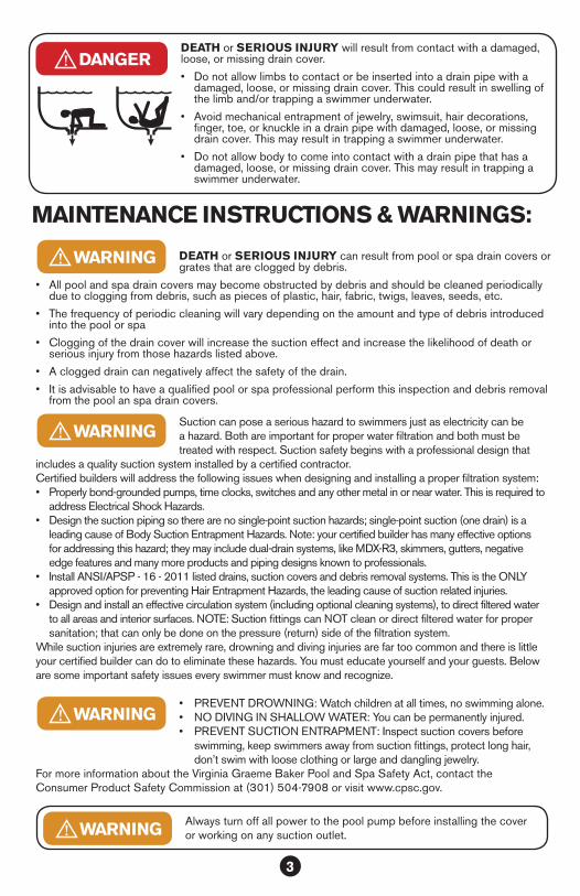
MAINTENANCE INSTRUCTIONS & WARNINGS:
DANGERDEATH or SERIOUS INJURY will result from contact with a damaged, loose, or missing drain cover.
• Do not allow limbs to contact or be inserted into a drain pipe with a damaged, loose, or missing drain cover. This could result in swelling of the limb and/or trapping a swimmer underwater.
• Avoid mechanical entrapment of jewelry, swimsuit, hair decorations, finger, toe, or knuckle in a drain pipe with damaged, loose, or missing drain cover. This may result in trapping a swimmer underwater.
• Do not allow body to come into contact with a drain pipe that has a damaged, loose, or missing drain cover. This may result in trapping a swimmer underwater.
DEATH or SERIOUS INJURY can result from pool or spa drain covers or grates that are clogged by debris.
• All pool and spa drain covers may become obstructed by debris and should be cleaned periodically due to clogging from debris, such as pieces of plastic, hair, fabric, twigs, leaves, seeds, etc.
• The frequency of periodic cleaning will vary depending on the amount and type of debris introduced into the pool or spa
• Clogging of the drain cover will increase the suction effect and increase the likelihood of death or serious injury from those hazards listed above.
• A clogged drain can negatively affect the safety of the drain.
• It is advisable to have a qualified pool or spa professional perform this inspection and debris removal from the pool an spa drain covers.
WARNING
Suction can pose a serious hazard to swimmers just as electricity can be a hazard. Both are important for proper water filtration and both must be treated with respect. Suction safety begins with a professional design that
includes a quality suction system installed by a certified contractor. Certified builders will address the following issues when designing and installing a proper filtration system:• Properly bond-grounded pumps, time clocks, switches and any other metal in or near water. This is required to
address Electrical Shock Hazards. • Design the suction piping so there are no single-point suction hazards; single-point suction (one drain) is a
leading cause of Body Suction Entrapment Hazards. Note: your certified builder has many effective options for addressing this hazard; they may include dual-drain systems, like MDX-R3, skimmers, gutters, negative edge features and many more products and piping designs known to professionals.
• Install ANSI/APSP - 16 - 2011 listed drains, suction covers and debris removal systems. This is the ONLY approved option for preventing Hair Entrapment Hazards, the leading cause of suction related injuries.
• Design and install an effective circulation system (including optional cleaning systems), to direct filtered water to all areas and interior surfaces. NOTE: Suction fittings can NOT clean or direct filtered water for proper sanitation; that can only be done on the pressure (return) side of the filtration system.
While suction injuries are extremely rare, drowning and diving injuries are far too common and there is little your certified builder can do to eliminate these hazards. You must educate yourself and your guests. Below are some important safety issues every swimmer must know and recognize.
• PREVENT DROWNING: Watch children at all times, no swimming alone. • NO DIVING IN SHALLOW WATER: You can be permanently injured. • PREVENT SUCTION ENTRAPMENT: Inspect suction covers before
swimming, keep swimmers away from suction fittings, protect long hair, don’t swim with loose clothing or large and dangling jewelry.
For more information about the Virginia Graeme Baker Pool and Spa Safety Act, contact the Consumer Product Safety Commission at (301) 504-7908 or visit www.cpsc.gov.
Always turn off all power to the pool pump before installing the cover or working on any suction outlet. WARNING
WARNING
WARNING

4
PARASKIM OVERVIEW
NOTICEInstallation must comply with all current applicable codes, including NSF Standard 50 (if required). Equalizer lines may be required on public pool or commercial pool installations.
1. For commercial installations use one skimmer per 500 square feet of pool surface area. Suction line sizes are based on a water velocity of less than six feet per second. Since building codes vary, check your local building code before installing pool and skimmers.
2. Suction line sizes for each section of piping must allow for the total number of skimmers feeding that section of the line.
3. For good hydraulic balance, divide skimmers as equally as possible between the main branches of the piping layout. Optionally run each skimmer back individually to the equipment pad and valve each line so they can be adjusted.
4. For long pipe runs (in which friction can reduce flow and pressure), refer to a friction/flow chart for proper pipe sizes.
5. When planning location of skimmers on one- and two-skimmer outdoor pools, locate skimmers so that the prevailing wind blows into the skimmers.
6. Paraskim will take up to 100 gpm over the weir without cavitation. 60 gpm with 2” direct suction, 90 gpm with immediate transition up to 2½” pipe. Plus venturi generated flow.
TABLE OF CONTENTSPARASKIM OVERVIEW ............................................................................................................................................ 4GENERAL INSTALLATION INSTRUCTIONS ..................................................................................................... 4MOUNTING PARASKIMV TO VINYL/FIBERGLASS POOL WALL ............................................................. 6PARASKIM V VENTURI STYLE PLUMBING....................................................................................................... 9OPTIONAL VENTURI OZONE FEED LINE ......................................................................................................10PARASKIM NON-VENTURI STYLE PLUMBING .............................................................................................11PRESSURE TEST.....................................................................................................................................................12CONCRETE DECK RECOMMENDATIONS ....................................................................................................12OPERATION STANDARD SKIMMER .................................................................................................................13OPERATION VENTURI SKIMMER ......................................................................................................................13OPTIONAL EQUALIZER VALVE & FLOAT VALVE INSTALLATION ..............................................................14MAINTENANCE & WINTERIZING .......................................................................................................................14TROUBLESHOOTING ............................................................................................................................................15PARASKIM VINYL SKIMMER PARTS .................................................................................................................16PARASKIM VINYL WIDE MOUTH SKIMMER PARTS ...................................................................................17PARASKIMV VENTURI VINYL SKIMMER PARTS ...........................................................................................18PARASKIMV VENTURI ..........................................................................................................................................19VINYL WIDE MOUTH SKIMMER PARTS ..........................................................................................................19PARASKIM FIBERGLASS SKIMMER PARTS ..................................................................................................20PARASKIMV VENTURI ...........................................................................................................................................21FIBERGLASS SKIMMER PARTS ........................................................................................................................21PARASKIM & PARASKIM V SPECS - VINYL ....................................................................................................22PARASKIM & PARASKIM V SPECS - VINYL WIDE MOUTH ......................................................................23PARASKIM & PARASKIM V SPECS - FIBERGLASS .....................................................................................24

5
GENERAL INSTALLATION INSTRUCTIONS
Paraskim™ Venturi Skimmer (Vinyl & Fiberglass) Installation (For skimmer dimensions, see 22)NOTICE: When the skimmer is formed into the concrete shell of the pool it MUST be surrounded by at least 4" of structural concrete in a monolithic pour, using a cold joint as shown in installation drawings (Fig. 1a).CAUTION: Plastic solvent cements and primers can be flammable, poisonous, or both. Closely follow solvent cement manufacturer’s instructions when using solvent cement.CAUTION: In residential installations where equalizers are not required and where the main drain lines do not connect to the skimmer equalizer port, low water levels in the pool, spa, or hot tub or clogged skimmer baskets may damage the pump due to loss of prime (if skimmer pulls air) or cavitation (if skimmer clogs). Air pulled in by skimmer(s) can be trapped in filter tanks, which may be a safety hazard. If skimmer regularly vortexes or sucks air, raise water level or contact your pool service representative for advice.1. For optimum skimmer functionality, the skimmer should be placed relative to the prevailing wind and
water flow direction. 2. Assemble piping and pipe fittings to skimmer. All piping must conform to current local and state
plumbing and sanitary codes.3. Long pipe runs and elbows restrict water flow. For best efficiency, use the fewest possible fitting
and 2" pipe for 2" skimmers). Using sweep 90˚ fittings or two 45˚ fittings in place of a single 90 is more efficient.
4. For pressure testing seal off any used skimmer ports.
Over tightening the threaded plugs may result in failure of the plug or the skimmer body and will not be covered under the terms of the Limited Warranty.DO NOT use tapered metal plugs as this will void manufacturer’s warranty.
DO NOT use “Rector Seal” or other thread paste intended for gas pipe installations as this will attack the plastic and cause failure of the skimmer body and will not be covered under the terms of the Limited Warranty.
NOTICE
5. Support skimmer securely in position. Unused ports may be used to install a standpipe for the skimmer to rest on. The deck ring collar has a friction fit that allows 3½" of vertical adjustment. Additional collars may be stacked upon each other to accommodate desk height as needed.
6. Ensure piping is adequately supported on undisturbed earth. If additional backfilled and tamping is necessary, do not stress pipe or skimmer port by lifting or moving pipe after skimmer port connections have been made.
7. Structural gunite/concrete should be applied in a monolithic pour, in conjunction with a cold joint as shown in Fig. 1a.
8. Optional Overflow Line – Using a 1½" hole saw drill out the overflow port at side top of skimmer to install overflow line. Plumb with a 1½" or 2" (2" pipe requires coupler) properly sloped line so that water flows away from the pool to desired point of discharge.
VINYL LINER
11"
2A
POOL WALL
OVERFLOWPORT
Fig. 1a Vinyl through wall
FIBERGLASS POOL SHELL
2B
POOL WALL
OVERFLOWPORT
Fig. 1b Fiberglass/vinyl back mount (flush)
6
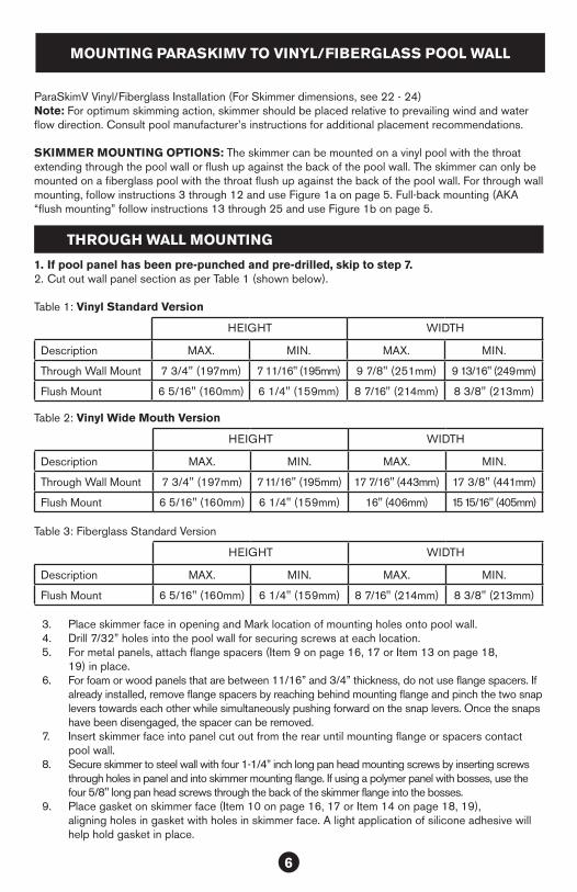
MOUNTING PARASKIMV TO VINYL/FIBERGLASS POOL WALL
ParaSkimV Vinyl/Fiberglass Installation (For Skimmer dimensions, see 22 - 24)Note: For optimum skimming action, skimmer should be placed relative to prevailing wind and water flow direction. Consult pool manufacturer’s instructions for additional placement recommendations.
SKIMMER MOUNTING OPTIONS: The skimmer can be mounted on a vinyl pool with the throat extending through the pool wall or flush up against the back of the pool wall. The skimmer can only be mounted on a fiberglass pool with the throat flush up against the back of the pool wall. For through wall mounting, follow instructions 3 through 12 and use Figure 1a on page 5. Full-back mounting (AKA “flush mounting” follow instructions 13 through 25 and use Figure 1b on page 5.
1. If pool panel has been pre-punched and pre-drilled, skip to step 7.2. Cut out wall panel section as per Table 1 (shown below).
Table 1: Vinyl Standard Version
HEIGHT WIDTH
Description MAX. MIN. MAX. MIN.
Through Wall Mount 7 3/4" (197mm) 7 11/16" (195mm) 9 7/8" (251mm) 9 13/16" (249mm)
Flush Mount 6 5/16" (160mm) 6 1/4" (159mm) 8 7/16" (214mm) 8 3/8" (213mm)
Table 2: Vinyl Wide Mouth Version
HEIGHT WIDTH
Description MAX. MIN. MAX. MIN.
Through Wall Mount 7 3/4" (197mm) 7 11/16" (195mm) 17 7/16" (443mm) 17 3/8" (441mm)
Flush Mount 6 5/16" (160mm) 6 1/4" (159mm) 16" (406mm) 15 15/16" (405mm)
Table 3: Fiberglass Standard Version
HEIGHT WIDTH
Description MAX. MIN. MAX. MIN.
Flush Mount 6 5/16" (160mm) 6 1/4" (159mm) 8 7/16" (214mm) 8 3/8" (213mm)
3. Place skimmer face in opening and Mark location of mounting holes onto pool wall.4. Drill 7/32” holes into the pool wall for securing screws at each location.5. For metal panels, attach flange spacers (Item 9 on page 16, 17 or Item 13 on page 18,
19) in place.6. For foam or wood panels that are between 11/16” and 3/4” thickness, do not use flange spacers. If
already installed, remove flange spacers by reaching behind mounting flange and pinch the two snap levers towards each other while simultaneously pushing forward on the snap levers. Once the snaps have been disengaged, the spacer can be removed.
7. Insert skimmer face into panel cut out from the rear until mounting flange or spacers contact pool wall.
8. Secure skimmer to steel wall with four 1-1/4” inch long pan head mounting screws by inserting screws through holes in panel and into skimmer mounting flange. If using a polymer panel with bosses, use the four 5/8" long pan head screws through the back of the skimmer flange into the bosses.
9. Place gasket on skimmer face (Item 10 on page 16, 17 or Item 14 on page 18, 19), aligning holes in gasket with holes in skimmer face. A light application of silicone adhesive will help hold gasket in place.
THROUGH WALL MOUNTING

7
10. Install vinyl liner. Follow pool manufacturer’s instructions for proper vinyl liner installations. The pool should be filled with approximately two (2) feet of water so the liner is stretched to the proper position prior to cutting in the skimmer.
11. Align second gasket and faceplate (Item 10 on page 16, 17 or Item 14 on page 18, 19) and tightly fastened to skimmer face with flathead face plate screws provided (Item 10 on page 16, 17 or Item 14 on page 18, 19). Pierce liner through face plate holes one at a time prior to inserting screws.
12. Once faceplate screws are completely tightened. Cut out vinyl liner along the inside edges of faceplate, snap on colored cover to hide screws. Skip to step 26 for piping instructions.
13. For Vinyl Pools: If pool panel has been pre-punched and pre-drilled, skip to step 19.14. For vinyl & fiberglass pools not pre-cutout. Cut out wall panel section as described in
Table 1 or 2 on 6.15. Using faceplate (Item 10 on page 16, 17
or Item 14 on page 18, 19), (Item 9 on page 20, 21) mark location of mounting holes. See Fig. 1c and Fig. 1d for holes used in flush mounting skimmers.
16. Drill 7/32” holes located in step 15.17. Place gasket against pool wall again and mark
location of remaining holes.18. Drill 9/32” holes for faceplate screws located
in step 17.19. Place gasket on skimmer face, aligning holes in
gasket with holes in skimmer face. Use a light application of silicone adhesive to help hold gasket in place.
NOTICEDo not obstruct the venturi return line with an eyeball, main drain covers or other type of fitting. Use only the supplied Return Guard. Described in step 20.
20. Secure skimmer to wall with four pan head mounting screws provided (Item 13). Use 5/8” long pan head screws for pool walls from 1/8” to 1/4” thick. Use 1-1/4” long pan head screws for pool walls from 1/4” to 1/2” thick.
21. Install the Return Guard Bulkhead fitting to the right of the skimmer from outside the pool at dimensions shown in diagrams for vinyl and fiberglass.
a. For steel wall cut a 4 ½” hole using a Greenlee® Standard Round Knockout Punch (Greenlee.com - Cat. No. 742BB / UPC No. 19978).
b. For a composite, wood or fiberglass wall cut a 4 ½” hole using a 4 ½” hole saw. Then clean the burr off hole edge before inserting bulkhead.
c. For a vinyl pool installation insert the Return Guard Bulkhead in the hole in the wall from the inside and secure with the backing nut. You may have to trim support ribs on the back side of the wall to make room for the bulkhead nut.
d. For a fiberglass pool installation apply silicone sealant to the back of the Return Bulkhead Fitting flange. Insert into the hole in the pool wall from the inside and apply silicone to the outside of the pool wall. DO NOT FORCE BULKHEAD THROUGH THE HOLE, THIS MAY DAMAGE
BACK MOUNTING
Fig. 1c
9/32" mounting holes
9/32" mounting holes
Fig. 1d
1 3/4" (45mm)
23 11
/16"
(600
mm
)
23 11
/16"
(600
mm
)
1 3/4" (45mm)
Vinyl Vinyl Wide Mouth Fiberglass
11278.61mm
21 14
540mm

8
THREADS. Secure with the backing nut.
NOTICE Before back filling around the pool make the plumbing connection to the skimmer including between return port and the bulkhead fitting with 2” rigid PVC pipe. Do not use 90 degree elbows or reduce the venturi pool return line.
22. Install vinyl liner. Follow pool manufacturer’s instructions for proper vinyl liner installation. The pool should be filled with approximately two (2) feet of water so the liner is stretched to the proper position prior to cutting in the skimmer.
23. Align second gasket and faceplate (part #005-702-9400-XX or #005-702-2971-00) and tightly fastened to skimmer face with flathead faceplate screws provided. Pierce liner through faceplate holes one at a time prior to inserting screws. Screws secure through: (A) Faceplate, (B) Gasket, and into (F) Skimmer Face.
24. Cut out vinyl liner along the inside edges of faceplate. Snap on colored cover to hide screws.a. For a vinyl pool. Prior to installing the Vinyl Liner, apply adhesive to the non-ribbed side
of the two notched gaskets. Align the gaskets with the alignment tabs and screw holes on the Return Guard Bulkhead, then press the gaskets onto the Bulkhead Fitting and the Bulkhead Seal Ring.
b. After installing the Vinyl Liner, align the Bulkhead Seal Ring with the alignment tab in the Return Guard Bulkhead Fitting. (Fig. 2a) and install five(5) self-tapping screws through the Seal Ring. Secure the screws without over tightening.
c. Cut the Vinyl Liner out of the center of the Bulkhead along the inside of the Seal Ring.d. Insert the Return Guard Cover into the Bulkhead and secure with three screws.
Completely hand tighten screws. Do not use power tools.e. For a fiberglass pool align the gaskets and seal ring with the alignment tabs and screw
holes on the Return Guard Bulkhead (Fig. 2b) and secure the screws without over tightening. These parts are need to properly space the Return Guard Cover.
f. Insert the Return Guard Cover into the Bulkhead and secure with three screws. Completely hand tighten screws. Do not use power tools.
25. Install any additional supports as supplied or recommended by the pool wall manufacturers.26. Assemble piping and pipe fittings to skimmer. All piping must conform to local and state
plumbing and sanitary codes. See next section for specific plumbing connections. 27. Caution: When gluing PVC pipe into an PVC skimmer, you must use primer as recommended
by the glue manufacturer. This will ensure PVC and PVC cement compatibility and a leak free joint.
28. Caution: Ensure piping is adequately supported on undisturbed earth. If additional backfilling and tamping is necessary, do not stress pipe or skimmer port by lifting or moving pipe after skimmer port connections have been made.
29. Seal off any use skimmer ports with O-ring style plugs provided.
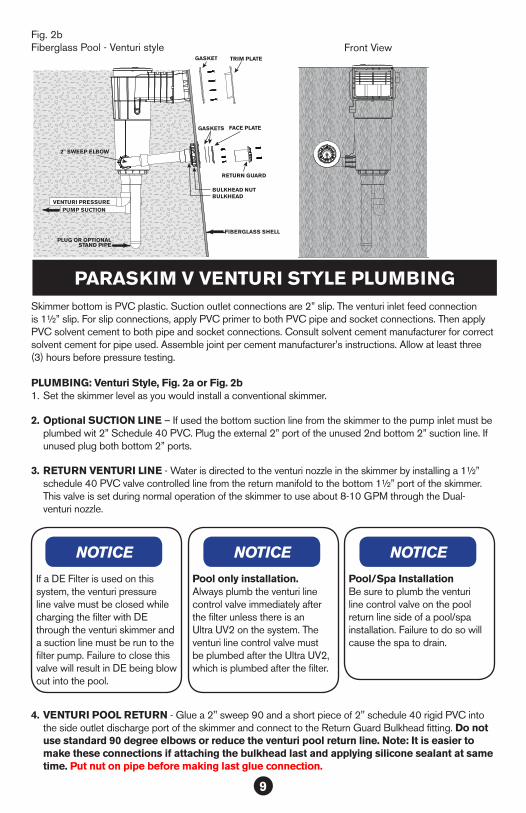
Fig. 2aVinyl Pool - Venturi style
Front ViewPOOL WALL
VINYL LINER
FACE PLATE TRIM PLATE
GASKETS SCREWS
GASKETS
RETURN GUARD
BULKHEAD NUTBULKHEAD
FACE PLATE
VENTURI PRESSUREPUMP SUCTION
9
PARASKIM V VENTURI STYLE PLUMBINGSkimmer bottom is PVC plastic. Suction outlet connections are 2” slip. The venturi inlet feed connection is 1½” slip. For slip connections, apply PVC primer to both PVC pipe and socket connections. Then apply PVC solvent cement to both pipe and socket connections. Consult solvent cement manufacturer for correct solvent cement for pipe used. Assemble joint per cement manufacturer’s instructions. Allow at least three (3) hours before pressure testing. PLUMBING: Venturi Style, Fig. 2a or Fig. 2b1. Set the skimmer level as you would install a conventional skimmer.
2. Optional SUCTION LINE – If used the bottom suction line from the skimmer to the pump inlet must be plumbed wit 2” Schedule 40 PVC. Plug the external 2” port of the unused 2nd bottom 2” suction line. If unused plug both bottom 2” ports.
3. RETURN VENTURI LINE - Water is directed to the venturi nozzle in the skimmer by installing a 1½” schedule 40 PVC valve controlled line from the return manifold to the bottom 1½” port of the skimmer. This valve is set during normal operation of the skimmer to use about 8-10 GPM through the Dual- venturi nozzle.
Pool only installation. Always plumb the venturi line control valve immediately after the filter unless there is an Ultra UV2 on the system. The venturi line control valve must be plumbed after the Ultra UV2, which is plumbed after the filter.
NOTICE
Pool/Spa InstallationBe sure to plumb the venturi line control valve on the pool return line side of a pool/spa installation. Failure to do so will cause the spa to drain.
NOTICENOTICE
If a DE Filter is used on this system, the venturi pressure line valve must be closed while charging the filter with DE through the venturi skimmer and a suction line must be run to the filter pump. Failure to close this valve will result in DE being blow out into the pool.
4. VENTURI POOL RETURN - Glue a 2" sweep 90 and a short piece of 2" schedule 40 rigid PVC into the side outlet discharge port of the skimmer and connect to the Return Guard Bulkhead fitting. Do not use standard 90 degree elbows or reduce the venturi pool return line. Note: It is easier to make these connections if attaching the bulkhead last and applying silicone sealant at same time. Put nut on pipe before making last glue connection.
Fig. 2bFiberglass Pool - Venturi style Front View
VENTURI PRESSUREPUMP SUCTION
FIBERGLASS SHELL
PLUG OR OPTIONALSTAND PIPE
BULKHEAD NUTBULKHEAD
GASKETS
GASKET TRIM PLATE
FACE PLATE
RETURN GUARD
2" SWEEP ELBOW
10
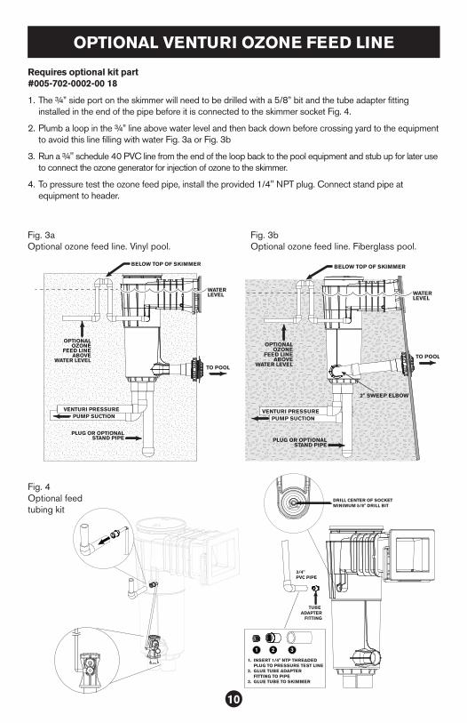
TUBE ADAPTER
FITTING
1. INSERT 1/4" NTP THREADED PLUG TO PRESSURE TEST LINE2. GLUE TUBE ADAPTER FITTING TO PIPE3. GLUE TUBE TO SKIMMER
3/4"PVC PIPE
DRILL CENTER OF SOCKET MINIMUM 5/8" DRILL BIT
1 2 3
Requires optional kit part #005-702-0002-00 18
1. The ¾” side port on the skimmer will need to be drilled with a 5/8” bit and the tube adapter fitting installed in the end of the pipe before it is connected to the skimmer socket Fig. 4.
2. Plumb a loop in the ¾” line above water level and then back down before crossing yard to the equipment to avoid this line filling with water Fig. 3a or Fig. 3b
3. Run a ¾" schedule 40 PVC line from the end of the loop back to the pool equipment and stub up for later use to connect the ozone generator for injection of ozone to the skimmer.
4. To pressure test the ozone feed pipe, install the provided 1/4" NPT plug. Connect stand pipe at equipment to header.
TO POOL
VENTURI PRESSUREPUMP SUCTION
BELOW TOP OF SKIMMER
OPTIONALOZONE
FEED LINEABOVE
WATER LEVEL
WATER LEVEL
PLUG OR OPTIONALSTAND PIPE
TO POOL
VENTURI PRESSUREPUMP SUCTION
BELOW TOP OF SKIMMER
OPTIONALOZONE
FEED LINEABOVE
WATER LEVEL
WATER LEVEL
PLUG OR OPTIONALSTAND PIPE
2" SWEEP ELBOW
Fig. 3a Optional ozone feed line. Vinyl pool.
Fig. 3b Optional ozone feed line. Fiberglass pool.
Fig. 4 Optional feed tubing kit
OPTIONAL VENTURI OZONE FEED LINE
11
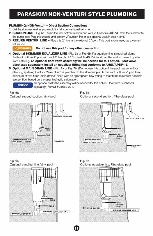
PARASKIM NON-VENTURI STYLE PLUMBING
PLUMBING: NON-Venturi – Direct Suction Connections1. Set the skimmer level as you would install a conventional skimmer. 2. SUCTION LINE – Fig. 5a. Plumb the rear bottom suction port with 2" Schedule 40 PVC from the skimmer to
the pump inlet. Plug the unused 2nd bottom 2" suction line or see optional uses in step 4 or 5.3. RETURN VENTURI LINE – Plug this 2" line in the external 2" port. This port is only used as a venturi
return line. WARNING Do not use this port for any other connection.
4. Optional SKIMMER EQUALIZER LINE - Fig. 6a or Fig. 6b. If a equalizer line is required plumb the front bottom 2" port with an 18" length of 2" Schedule 40 PVC and cap the end to prevent gunite from entering. An optional float valve assembly will be needed for this option. Float valve purchased separately. Install an equalizer fitting that conforms to ANSI/APSP-16.
5. Optional MAIN DRAIN LINE – Fig. 7a or Fig. 7b. (Do not use this option if the pool has an in-floor cleaning system.) If a floor “Main Drain" is plumbed to the skimmer plumb the front bottom 2" port to a minimum of two floor “main drains" sized with an appropriate flow rating to match the maximum possible system flow based on a proper hydraulic calculation.
VINYL LINER
FACE PLATE TRIM PLATE
PUMP SUCTION
PLUG
OPTIONAL SUCTION
PLUG
Fig. 5aOptional second suction. Vinyl pool
PUMP SUCTION
PLUGUNUSEDPORT
OPTIONAL SUCTION
PLUG
FIBERGLASS SHELL
FACE PLATE TRIM PLATE
Fig. 5bOptional second suction. Fiberglass pool
NOTICEAn optional float valve assembly will be needed for this option. Float valve purchased separately. Pentair #08650-0017
PUMP SUCTION
PLUG
OPTIONAL EQUALIZER LINE
PLUG
PUMP SUCTION
PLUGUNUSEDPORT
OPTIONAL EQUALIZER LINE
PLUG
Fig. 6aOptional equalizer line. Vinyl pool
Fig. 6bOptional equalizer line. Fiberglass pool

12
PRESSURE TEST
PRESSURE TESTING: DO NOT USE THREAD SEALANT OF ANY TYPE OR METAL PLUGSUSE A PLASTIC NPT PLUG OR NIPPLE STAND PIPE.To pressure test the 1½” line from the equipment to the skimmer. Plug the inlet fitting on the inside of the skimmer. Plug the used suction port(s) in the bottom of the skimmer so that the suction line(s) can be pressure tested at the same time. DO NOT OVER-TIGHTEN THESE PLUGS! DO NOT USE A PETROLEUM BASED LUBRICANT!
CONCRETE DECK RECOMMENDATIONS
If a concrete deck is to be poured around the perimeter of the pool, follow pool wall manufacturer’s recommendations for backfilling and soil preparation prior to concrete deck installation. This is important to reduce the possibility of excess settling of the backfill after concrete deck installation which may result in cracking of the concrete deck.
After proper backfilling and soil preparation have been completed, the concrete deck may be poured following good standard concrete practices. Use high-quality concrete of sufficient strength for the size of deck being poured. Tool joints should be made as shown in Figure 3 to reduce and localize any cracks that occur in the deck due to the minor amounts of settling that can happen, even in well-prepared soil.
1. Remove the adjustable deck ring and cut away with a pair of side cutters or hack saw blade the extra deck ring slats that protrude down and block the skimmer throat. The throat should be completely open when the deck ring is set at desired deck thickness Fig. 11.
Fig. 11Cut off desired amount from the adjustable deck ring and replace back into skimmer
PUMP SUCTION
PLUG
OPTIONALMAIN DRAIN
LINE
PLUG
PUMP SUCTION
PLUG
PLUG
OPTIONALMAIN DRAIN
LINE
Fig. 7aOptional main drain line. Vinyl pool
Fig. 7bOptional main drain line. Fiberglass pool

13
OPERATION STANDARD SKIMMER
1. Install the weir door in the throat of the skimmer so that the spring loaded hinge pins pivot freely in the holes in the side of the throat allowing the weir door to move up and down with the water level Fig. 12. From front, insert one pin in hole in throat and twist down until pin on other side of weir door snaps into place.
2. After the pool is filled and is ready for startup remove all pressure test plugs.
3. Install basket4. Turn pump on5. Set control valves to desired flow to skimmer(s)
OPERATION VENTURI SKIMMER
1. Complete steps 1-5 above before proceeding.2. After running water through return line to clear any construction debris from the line install the dual
pressure nozzle in the venturi return line with the bayonet lugs by inserting and turning ¼ turn. Make sure the O-ring is in place or you may hear a squeal during operation. The pressure nozzles should face directly into the return port to the pool when twisted completely to the stop. Open the valve at the plumbing manifold fully. There is no further adjustment required.
DO NOT GLUE THE DUAL PRESSURE NOZZLE INTO THE FITTING! This must remain unglued so that it can be removed for cleaning or replacement and a threaded plug can be threaded into
the bottom port in the event that winterizing is necessary.
NOTICE
3. The venturi skimmer may be operated simultaneously with the normal skimmer functioning or the suction from the pump may be shut off or not installed allowing only venturi powered skimming action taking place. Either way, a much stronger skimming action will result when compared to a standard skimmer. NOTE: THE INSTALLED VALVE CONTROLLING THE SUCTION SHOULD BE LEFT SLIGHTLY OPEN. THERE ARE OCCASIONS WHEN THE PUMP MAY BE “STARVED” WHEN 100% OF THE SUCTION IS COMING THROUGH THE MAIN DRAINS ONLY.
4. If a D.E. Filter is installed one suction line is plumbed to at least one skimmer in the pool. This line only needs to be opened when charging the filter with D.E. Note: The venturi dual pressure nozzle valve must be closed and off while charging the D.E. or it will be blown out into the pool.
5. At start up with optional ozone venturi feed line. Before installing the dual pressure nozzle in the skimmer venturi return line, insert the short end of the tubing kit into the side of the dual nozzle assembly. Insert the dual nozzle into the skimmer then plug the long end of the tubing kit into the port on the side of the skimmer below the basket rim. Fig. 13
Fig. 12Install weir door
Fig. 13Optional ozone venturi feed line

14
OPTIONAL EQUALIZER VALVE & FLOAT VALVE INSTALLATION
SOMETIMES REQUIRED ON COMMERCIAL POOLS.
DANGERDEATH or SERIOUS INJURY will result if this product is not installed and used correctly.
OPTIONAL EQUALIZER VALVE INSTALLATION Fig. 141. Ensure the O-ring is in the retainer groove
of the equalizer valve (Pentair part #08655-0017) that comes with the float valve. Check for operation of the equalizer mechanism.
2. Install equalizer valve by threading valve into the skimmer equalizer line port as shown.
3. Be sure that pump port in bottom of skimmer is not blocked by trimmer plate and that the trimmer plate on the bottom of the float valve is moved as far as possible to the side of the valve.
OPTIONAL FLOAT VALVE INSTALLATION (Pentair part #08650-0079)1. Install the adapter ring on the ledge near the bottom of the skimmer.2. Place float valve into bottom of skimmer. Press to seat the O-ring in place.3. To increase water flow through the valve, slide the trimmer plate to uncover
the hole in the bottom of the valve. To decrease flow, slide the trimmer plate to cover the hole in the bottom of the valve.
OPERATIONWhen the water level drops below the weir of the skimmer, the water level in the skimmer will drop until the float valve closes. The equalizer valve will open at this time, allowing water to flow to the pump from the equalizer line. After the pump has been turned off, and the water level is raised to the appropriate level for good skimming action, the equalizer valve will close and the float valve will automatically open. Normal operation will resume when the pump is turned back on.
MAINTENANCE & WINTERIZING
• Weir: Periodically check weir for free operation. Replace if damaged or worn.• Strainer Basket: Check strainer basket every few days for accumulated leaves, debris, etc. Empty
basket and flush optional fine mesh bag as required. Reset float valve if it closed.• Float Valve: Optional: Periodically check that float valve is operating freely and is not waterlogged.
If necessary, tighten trimmer plate pivot screw to maintain desired flow balance.• Equalizer Valve (Public Pool Models): Inspect for wear or deterioration. Make sure that screw is
tight in equalizer valve body. If you can detect flow through equalizer with float valve open, replace check valve.
• Equalizer (Wall) Fittings: Daily check that Listed wall suction fittings are correctly installed and that covers are tight to fittings. Visually inspect for debris blocking cover. Remove any debris.
• Water Level: Maintain water level at least equal to the center of the weir door for proper operation. Adjust trimmer plate as necessary if equipped.
• Winterizing the Venturi version of the ParaskimV Skimmer. Normal winterizing is the same on the Paramount skimmer as other any other skimmer, with the exception of the Venturi version which will require a few additional steps.
FLOAT VALVE
O-RING
TRIMMERPLATE
SCREW
OPTIONALEQUALIZER LINE
OPTIONALFLOAT VALVE
TO PUMP
EQUALIZER VALVE
Fig. 14Start up
WARNING
15
1. Lower the pool water below the skimmer opening.2. Remove the Return Guard on the pool side of the Venturi discharge and place the
optional Paramount o-ring plug 004-702-9970-00 in the fitting. Alternatively, you may use a 2¾” rubber plug. Store the Return Guard and screws with the basket in a safe location. The return guard and plug use the same screws.
3. Remove the Dual Pressure Nozzle and ozone delivery tube if so equipped from the bottom of the skimmer and place with the skimmer basket.
4. Place a blow through plug in the bottom return port and blow the line back through the return header then close the valve at the pool return header.
5. Disconnect the ozone tubing from the standpipe at the equipment pad and blow the ozone line to the skimmer. Plug with a ¼ inch plug in the port in the inside side of the skimmer.
6. From this point treat the skimmer like any standard and blow out all line and plug. 7. Drain the skimmer of all water. 8. Insert a piece of foam rope in the venturi return line for added protection. 9. A device like a Gizmo or non-toxic antifreeze should also be used for safety from outside water
leaking in and causing damage from freezing.10. Cover skimmer to prevent rain water or snow accumulation: Falling and tripping hazard.
Additional methods may also be required. There are many methods to winterizing a pool and pool equipment. Different methods are used depending on regional conditions. It is the pool operator’s
responsibility to ensure all components of the pool and pool equipment are protected from the most severe freeze conditions in their specific area.
NOTICE
• Deck Lid: Skimmer deck lid may deteriorate with prolonged use. Cover must be flush with pool, spa, or hot tub deck level. Skimmer deck lid is made of impact and weather resistant materials, but extended use (5-7 years) may lead to reduced strength. Regularly check condition of skimmer lid. Look for cracks, chips, deterioration of plastic, etc. Replace deck lid if any sign of damage or deterioration is found.
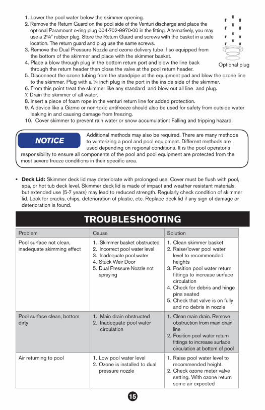
Problem Cause Solution
Pool surface not clean, inadequate skimming effect
1. Skimmer basket obstructed2. Incorrect pool water level3. Inadequate pool water4. Stuck Weir Door5. Dual Pressure Nozzle not
spraying
1. Clean skimmer basket2. Raise/lower pool water
level to recommended heights
3. Position pool water return fittings to increase surface circulation
4. Check for debris and hinge pins seated
5. Check that valve is on fully and no debris in nozzle
Pool surface clean, bottom dirty
1. Main drain obstructed2. Inadequate pool water
circulation
1. Clean main drain. Remove obstruction from main drain line
2. Position pool water return fittings to increase surface circulation at bottom of pool
Air returning to pool 1. Low pool water level2. Ozone is installed to dual
pressure nozzle
1. Raise pool water level to recommended height.
2. Check ozone meter valve setting. With ozone return some air expected
TROUBLESHOOTING
Optional plug

16
Item Part Number Description1 004-702-40XX-XX Body assembly complete
2 005-702-3000-XX Door & weir assembly
3 005-252-4570-XX Deck lid
4 005-702-6000-XX Notched deck ring
5 005-152-2207-00 Basket
6 005-702-9100-XX Trimmer plate assembly
7 004-152-4517-00 Mesh bag, 600 Micron
9 005-702-9930-00 Flange spacer, 3 pack
10 005-702-9400-XX Face plate kit
PARASKIM VINYL SKIMMER PARTS
2
3
4
5
6
1
9
7
10

17
Item Part Number Description1 004-702-60XX-XX Body assembly complete
2 005-702-3000-XX Door & weir assembly
3 005-252-4570-XX Deck lid
4 005-702-6000-XX Notched deck ring
5 005-152-2207-00 Basket
6 005-702-9100-XX Trimmer plate assembly
7 004-152-4517-00 Mesh bag, 600 Micron
8 005-702-9930-00 Flange spacer, 3 pack
9 005-702-2971-XX Face plate kit wide mouth
PARASKIM VINYL WIDE MOUTH SKIMMER PARTS
2
3
4
5
6
1
7
8
9
18
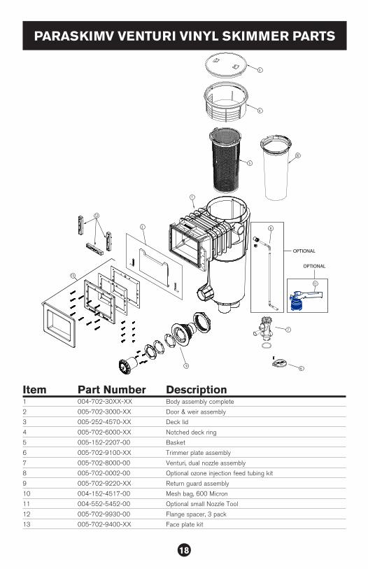
Item Part Number Description1 004-702-30XX-XX Body assembly complete
2 005-702-3000-XX Door & weir assembly
3 005-252-4570-XX Deck lid
4 005-702-6000-XX Notched deck ring
5 005-152-2207-00 Basket
6 005-702-9100-XX Trimmer plate assembly
7 005-702-8000-00 Venturi, dual nozzle assembly
8 005-702-0002-00 Optional ozone injection feed tubing kit
9 005-702-9220-XX Return guard assembly
10 004-152-4517-00 Mesh bag, 600 Micron
11 004-552-5452-00 Optional small Nozzle Tool
12 005-702-9930-00 Flange spacer, 3 pack
13 005-702-9400-XX Face plate kit
PARASKIMV VENTURI VINYL SKIMMER PARTS
2
3
4
5
8
11
7
6
1
10
9
OPTIONAL
OPTIONAL
12
13
19
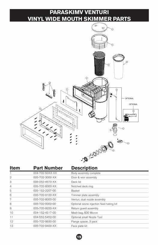
PARASKIMV VENTURI VINYL WIDE MOUTH SKIMMER PARTS
2
3
4
5
1
8
11
6
10
OPTIONAL
OPTIONAL
9
7
12
13
Item Part Number Description1 004-702-50XX-XX Body assembly complete
2 005-702-3000-XX Door & weir assembly
3 005-252-4570-XX Deck lid
4 005-702-6000-XX Notched deck ring
5 005-152-2207-00 Basket
6 005-702-9100-XX Trimmer plate assembly
7 005-702-8000-00 Venturi, dual nozzle assembly
8 005-702-0002-00 Optional ozone injection feed tubing kit
9 005-702-9220-XX Return guard assembly
10 004-152-4517-00 Mesh bag, 600 Micron
11 004-552-5452-00 Optional small Nozzle Tool
12 005-702-9930-00 Flange spacer, 3 pack
13 005-702-9400-XX Face plate kit
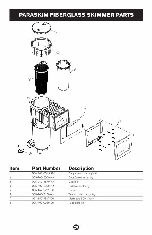
20
Item Part Number Description1 004-702-80XX-XX Body assembly complete
2 005-702-3000-XX Door & weir assembly
3 005-252-4570-XX Deck lid
4 005-702-6000-XX Notched deck ring
5 005-152-2207-00 Basket
6 005-702-9100-XX Trimmer plate assembly
7 004-152-4517-00 Mesh bag, 600 Micron
8 005-702-9960-00 Face plate kit
PARASKIM FIBERGLASS SKIMMER PARTS
8
2
3
4
5
6
1
7

21
Item Part Number Description1 004-702-70XX-XX Body assembly complete
2 005-702-3000-XX Door & weir assembly
3 005-252-4570-XX Deck lid
4 005-702-6000-XX Notched deck ring
5 005-152-2207-00 Basket
6 005-702-9100-XX Trimmer plate assembly
7 005-702-8000-00 Venturi, dual nozzle assembly
8 005-702-0002-00 Optional ozone injection feed tubing kit
9 005-702-9220-XX Return guard assembly
10 004-152-4517-00 Mesh bag, 600 Micron
11 004-552-5452-00 Optional small Nozzle Tool
12 005-702-9960-XX Face plate kit
PARASKIMV VENTURI FIBERGLASS SKIMMER PARTS
11
OPTIONAL
2
3
4
5
8
7
6
1
10
9
OPTIONAL
12
2
22
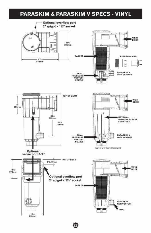
PARASKIM & PARASKIM V SPECS - VINYL
22½572mm
10254mm
105/8
270mm
29½749mm
1913/16
503mm
11¼286mm
27/8 , 72mm
121/4312mm
PARASKIM VWITH VENTURI
PARASKIM VWITH VENTURI
SHOWN WITHOUT BASKET
DUAL PRESSURE
VENTURINOZZLE
TOP OF BEAM
TOP OF BEAM
WEIR DOOR
RETURN GUARD
WEIR DOOR
OPTIONALOZONE INJECTIONFEED TUBE
DUAL PRESSURE
VENTURINOZZLE
BASKET
BASKET
WEIR DOOR
PLUG
PARASKIMNON VENTURI
Optional overflow port 2" spigot x 1½" socket
Optional overflow port 2" spigot x 1½" socket
Optional ozone port 3/4"
23
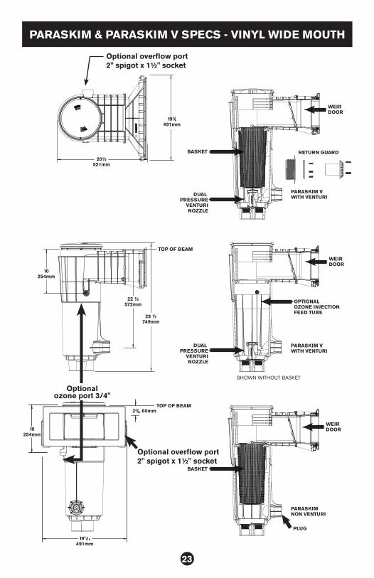
PARASKIM & PARASKIM V SPECS - VINYL WIDE MOUTH
PARASKIM VWITH VENTURI
PARASKIM VWITH VENTURI
SHOWN WITHOUT BASKET
DUAL PRESSURE
VENTURINOZZLE
TOP OF BEAM
TOP OF BEAM
WEIR DOOR
RETURN GUARD
WEIR DOOR
OPTIONALOZONE INJECTIONFEED TUBE
DUAL PRESSURE
VENTURINOZZLE
BASKET
BASKET
WEIR DOOR
PLUG
PARASKIMNON VENTURI
193/8491mm
20½521mm
10254mm
22 ½572mm
29 ½749mm
23/8, 60mm
195/16
491mm
10254mm
Optional overflow port 2" spigot x 1½" socket
Optional overflow port 2" spigot x 1½" socket
Optional ozone port 3/4"
24
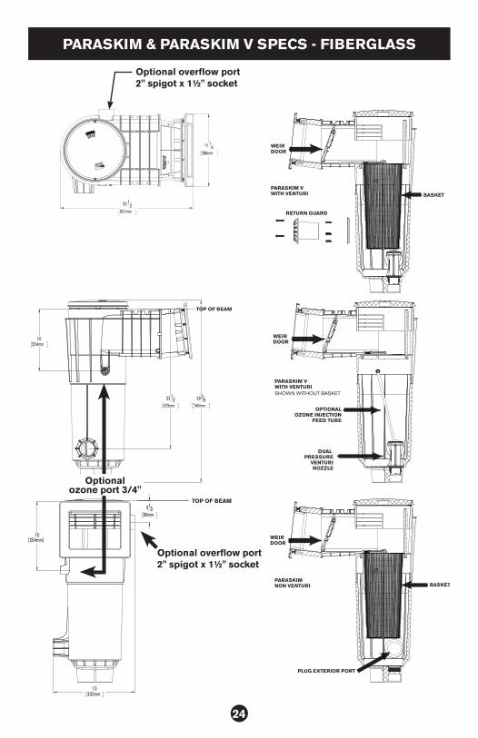
PARASKIM & PARASKIM V SPECS - FIBERGLASS
PARASKIM VWITH VENTURI
PARASKIM VWITH VENTURI
PLUG EXTERIOR PORT
SHOWN WITHOUT BASKET
TOP OF BEAM
TOP OF BEAM
WEIR DOOR
RETURN GUARD
WEIR DOOR
WEIR DOOR
OPTIONALOZONE INJECTION
FEED TUBE
DUAL PRESSURE
VENTURINOZZLE
BASKET
BASKETPARASKIMNON VENTURI
20 12
521mm
11 14
286mm
10254mm
2938
746mm 221
2572mm
10[254mm]
312
89mm
13330mm
Optional overflow port 2" spigot x 1½" socket
Optional overflow port 2" spigot x 1½" socket
Optional ozone port 3/4"