Embed Size (px)
Citation preview
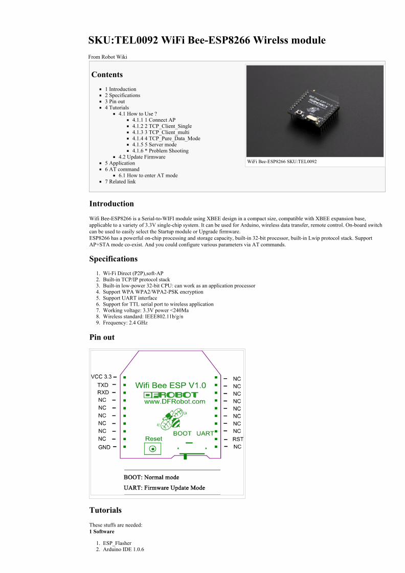
WiFi BeeESP8266 SKU:TEL0092
SKU:TEL0092 WiFi BeeESP8266 Wirelss moduleFrom Robot Wiki
Contents
1 Introduction2 Specifications3 Pin out4 Tutorials
4.1 How to Use ?4.1.1 1 Connect AP4.1.2 2 TCP_Client_Single4.1.3 3 TCP_Client_multi4.1.4 4 TCP_Pure_Data_Mode4.1.5 5 Server mode4.1.6 * Problem Shooting
4.2 Update Firmware5 Application6 AT command
6.1 How to enter AT mode7 Related link
Introduction
Wifi BeeESP8266 is a SerialtoWIFI module using XBEE design in a compact size, compatible with XBEE expansion base,applicable to a variety of 3.3V singlechip system. It can be used for Arduino, wireless data transfer, remote control. Onboard switchcan be used to easily select the Startup module or Upgrade firmware. ESP8266 has a powerful onchip processing and storage capacity, builtin 32bit processor, builtin Lwip protocol stack. SupportAP+STA mode coexist. And you could configure various parameters via AT commands.
Specifications
1. WiFi Direct (P2P),softAP2. Builtin TCP/IP protocol stack3. Builtin lowpower 32bit CPU: can work as an application processor4. Support WPA WPA2/WPA2PSK encryption5. Support UART interface6. Support for TTL serial port to wireless application7. Working voltage: 3.3V power <240Ma8. Wireless standard: IEEE802.11b/g/n9. Frequency: 2.4 GHz
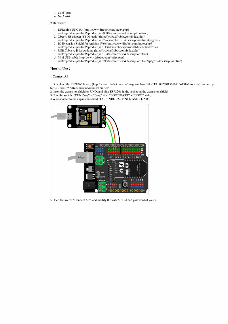
Pin out
Tutorials
These stuffs are needed: 1 Software
1. ESP_Flasher2. Arduino IDE 1.0.6
3. CoolTerm4. NetAssist
2 Hardware
1. DFRduino UNO R3 (http://www.dfrobot.com/index.php?route=product/product&product_id=838&search=uno&description=true)
2. Xbee USB adapter (FTDI ready) (http://www.dfrobot.com/index.php?route=product/product&product_id=72&search=USB&description=true&page=2)
3. IO Expansion Shield for Arduino (V6) (http://www.dfrobot.com/index.php?route=product/product&product_id=1134&search=expansion&description=true)
4. USB Cable AB for Arduino (http://www.dfrobot.com/index.php?route=product/product&product_id=134&search=usb&description=true)
5. Mini USB cable (http://www.dfrobot.com/index.php?route=product/product&product_id=215&search=usb&description=true&page=2&description=true)
How to Use ?
1 Connect AP
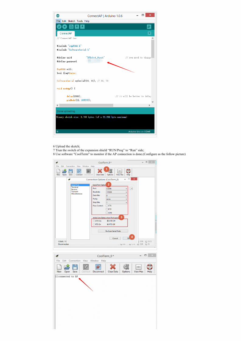
1 Download the ESP8266 library (http://www.dfrobot.com.cn/images/upload/File/TEL0092/2015050816413167nsek.rar), and unzip itto "C:\Users\***\Documents\Arduino\libraries" 2 Insert the expansion shield on UNO, and plug ESP8266 in the socket on the expansion shield. 3 Note the switch: “RUN/Prog” at “Prog” side; “BOOT/UART” at "BOOT" side; 4 Wire adapter to the expansion shield: TX PIN10, RX PIN11, GND GND;
5 Open the sketch "Connect AP", and modify the wifi AP ssid and password of yours;
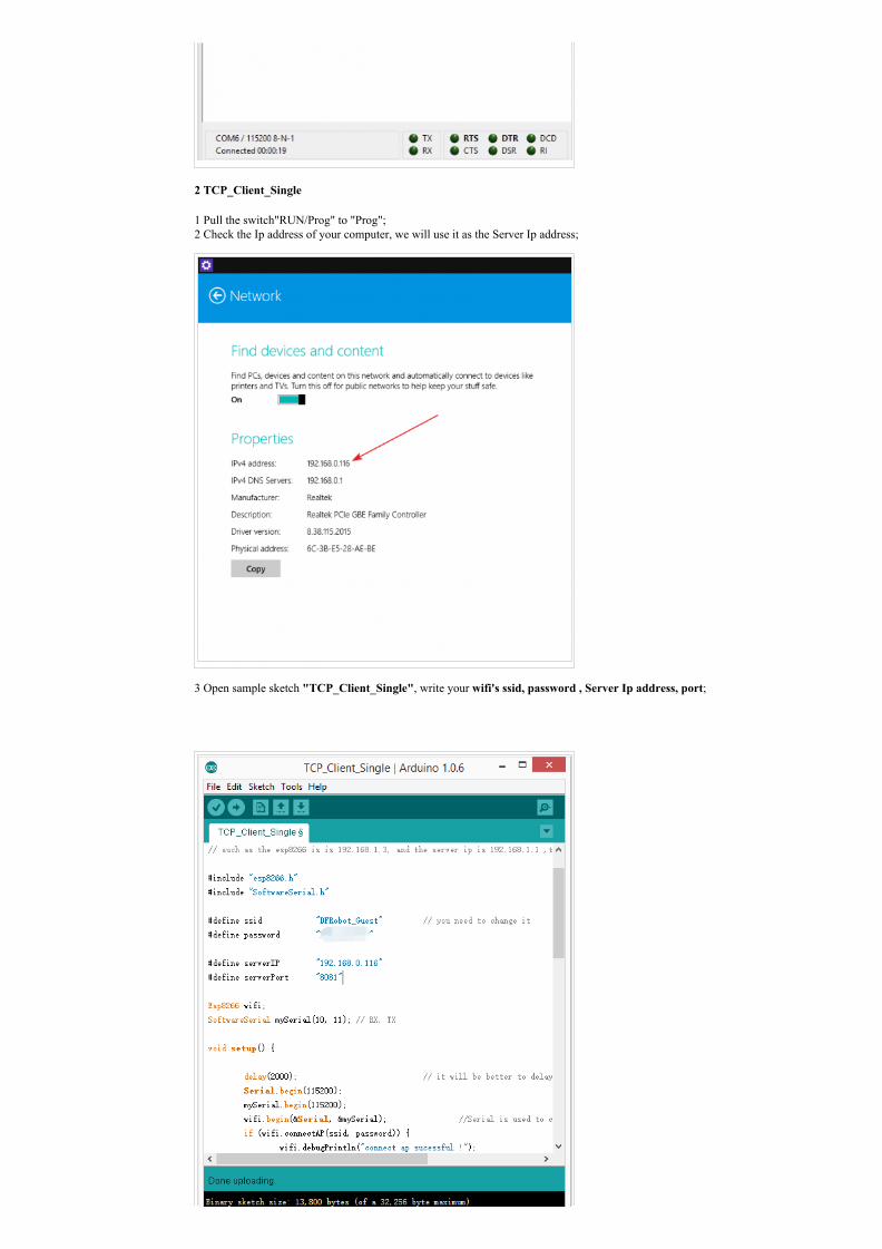
6 Upload the sketch; 7 Trun the switch of the expansion shield “RUN/Prog” to “Run” side; 8 Use software "CoolTerm" to monitor if the AP connection is done.(Configure as the follow picture)
2 TCP_Client_Single
1 Pull the switch"RUN/Prog" to "Prog"; 2 Check the Ip address of your computer, we will use it as the Server Ip address;
3 Open sample sketch "TCP_Client_Single", write your wifi's ssid, password , Server Ip address, port;
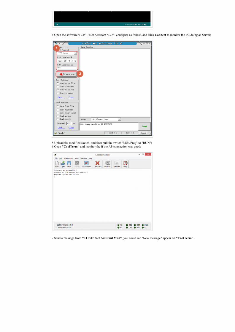
4 Open the software"TCP/IP Net Assistant V3.8", configure as follow, and click Connect to monitor the PC doing as Server;
5 Upload the modified sketch, and then pull the switch"RUN/Prog" to "RUN"; 6 Open "CoolTerm" and monitor the if the AP connection was good;
7 Send a message from "TCP/IP Net Assistant V3.8", you could see "New message" appear on "CoolTerm" .
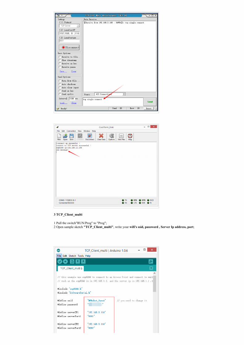
3 TCP_Client_multi
1 Pull the switch"RUN/Prog" to "Prog"; 2 Open sample sketch "TCP_Client_multi", write your wifi's ssid, password , Server Ip address, port;
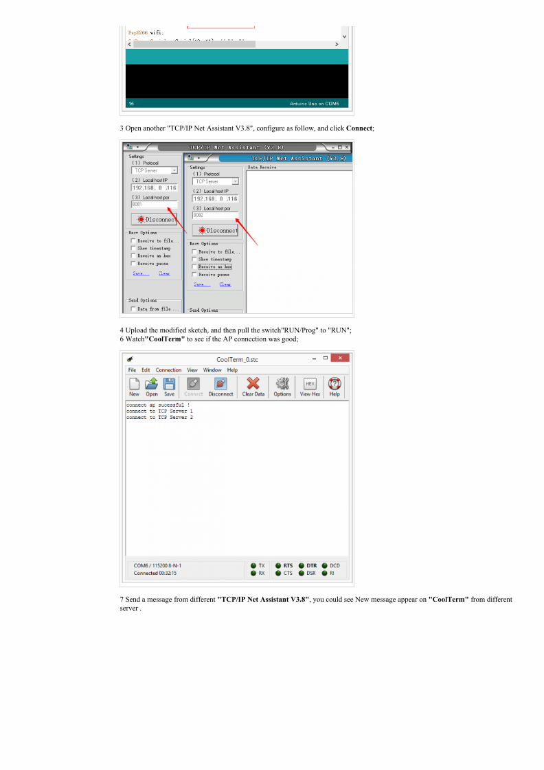
3 Open another "TCP/IP Net Assistant V3.8", configure as follow, and click Connect;
4 Upload the modified sketch, and then pull the switch"RUN/Prog" to "RUN"; 6 Watch"CoolTerm" to see if the AP connection was good;
7 Send a message from different "TCP/IP Net Assistant V3.8", you could see New message appear on "CoolTerm" from differentserver .
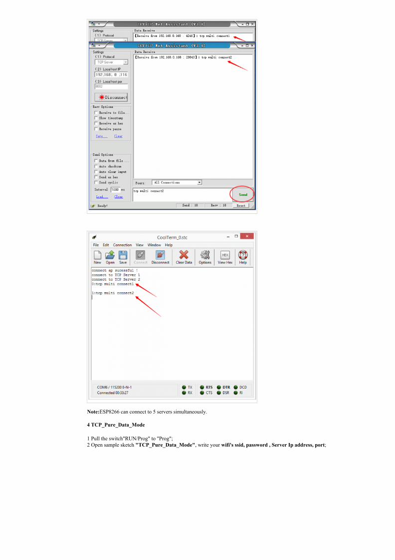
Note:ESP8266 can connect to 5 servers simultaneously.
4 TCP_Pure_Data_Mode
1 Pull the switch"RUN/Prog" to "Prog"; 2 Open sample sketch "TCP_Pure_Data_Mode", write your wifi's ssid, password , Server Ip address, port;
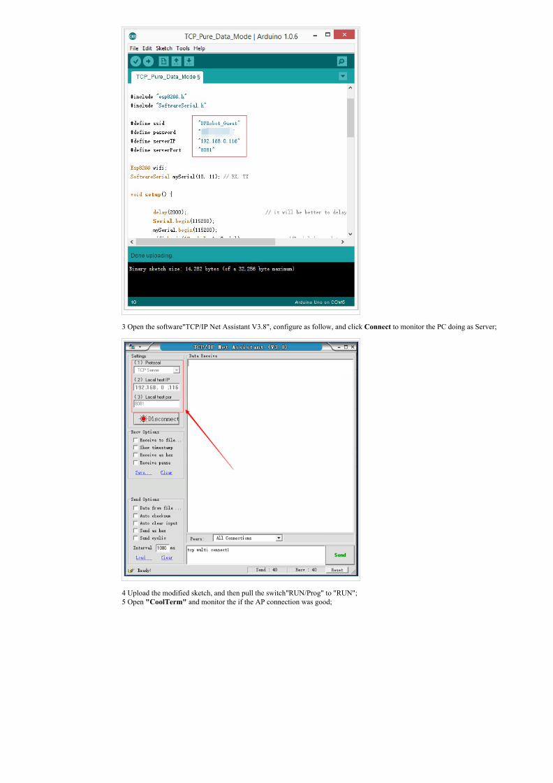
3 Open the software"TCP/IP Net Assistant V3.8", configure as follow, and click Connect to monitor the PC doing as Server;
4 Upload the modified sketch, and then pull the switch"RUN/Prog" to "RUN"; 5 Open "CoolTerm" and monitor the if the AP connection was good;
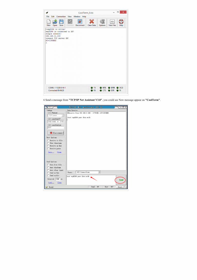
6 Send a message from "TCP/IP Net Assistant V3.8", you could see New message appear on "CoolTerm".
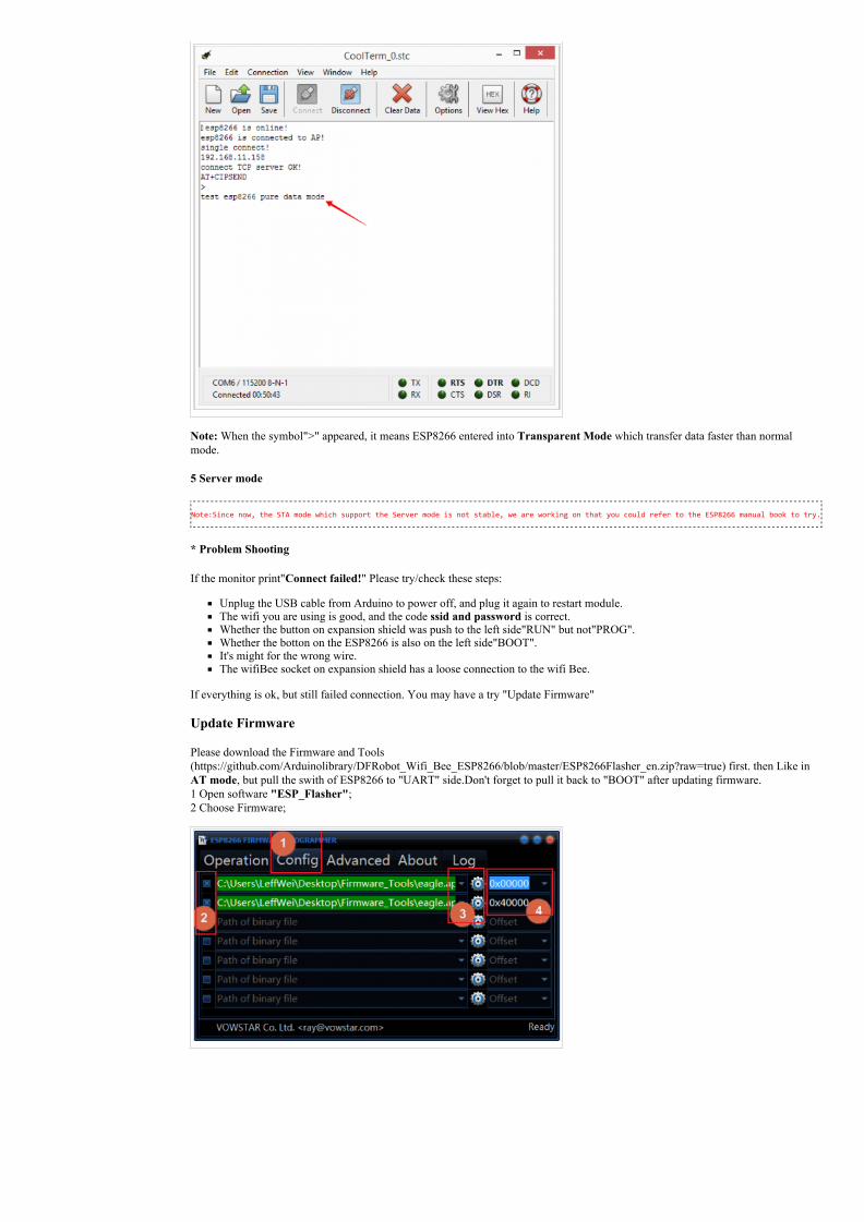
Note: When the symbol">" appeared, it means ESP8266 entered into Transparent Mode which transfer data faster than normalmode.
5 Server mode
Note:Since now, the STA mode which support the Server mode is not stable, we are working on that you could refer to the ESP8266 manual book to try.
* Problem Shooting
If the monitor print"Connect failed!" Please try/check these steps:
Unplug the USB cable from Arduino to power off, and plug it again to restart module.The wifi you are using is good, and the code ssid and password is correct.Whether the button on expansion shield was push to the left side"RUN" but not"PROG".Whether the botton on the ESP8266 is also on the left side"BOOT".It's might for the wrong wire.The wifiBee socket on expansion shield has a loose connection to the wifi Bee.
If everything is ok, but still failed connection. You may have a try "Update Firmware"
Update Firmware
Please download the Firmware and Tools(https://github.com/Arduinolibrary/DFRobot_Wifi_Bee_ESP8266/blob/master/ESP8266Flasher_en.zip?raw=true) first. then Like inAT mode, but pull the swith of ESP8266 to "UART" side.Don't forget to pull it back to "BOOT" after updating firmware. 1 Open software "ESP_Flasher"; 2 Choose Firmware;
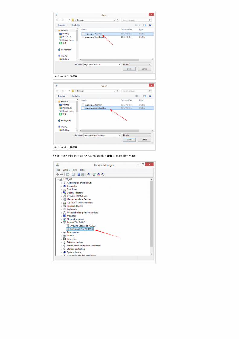
Address at 0x00000
Address at 0x40000
3 Choose Serial Port of ESP8266, click Flash to burn firmware;
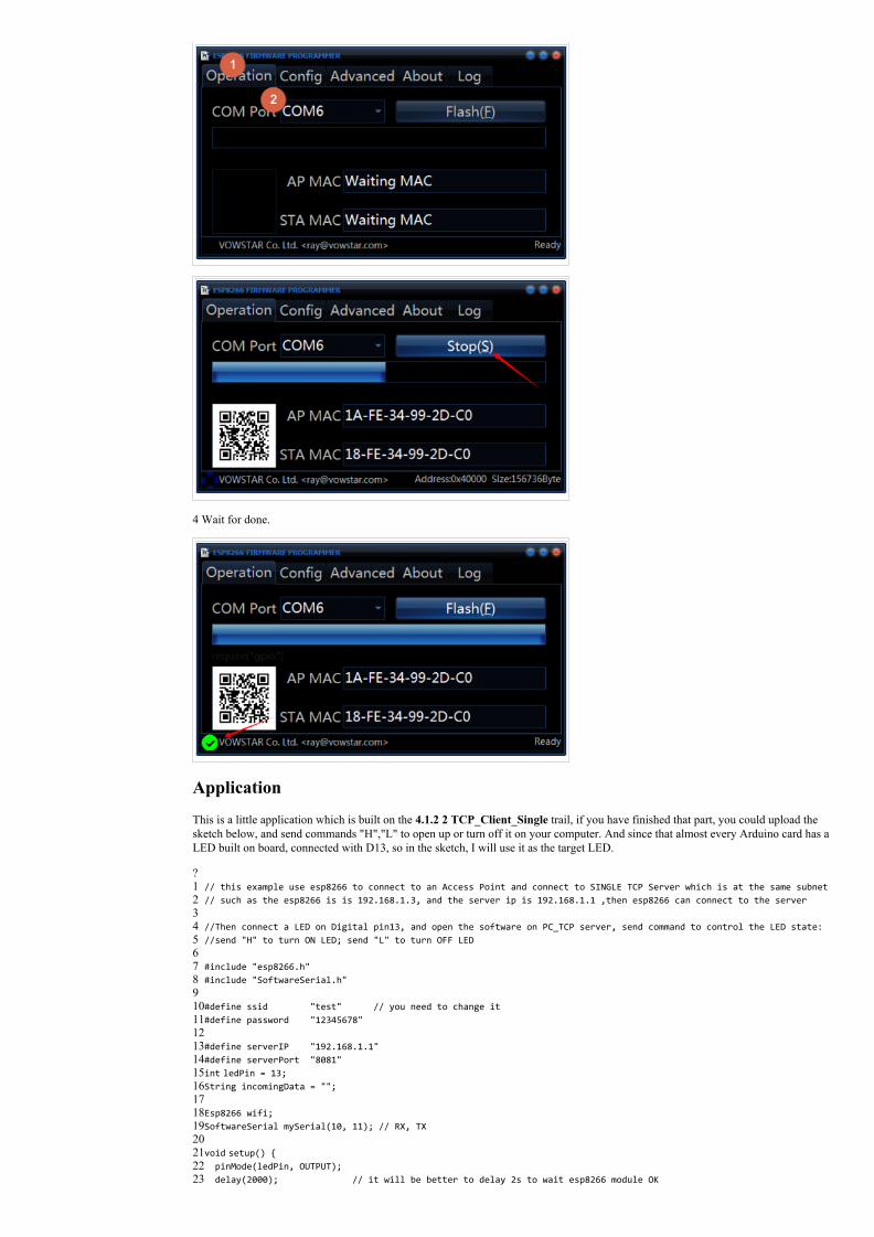
4 Wait for done.
Application
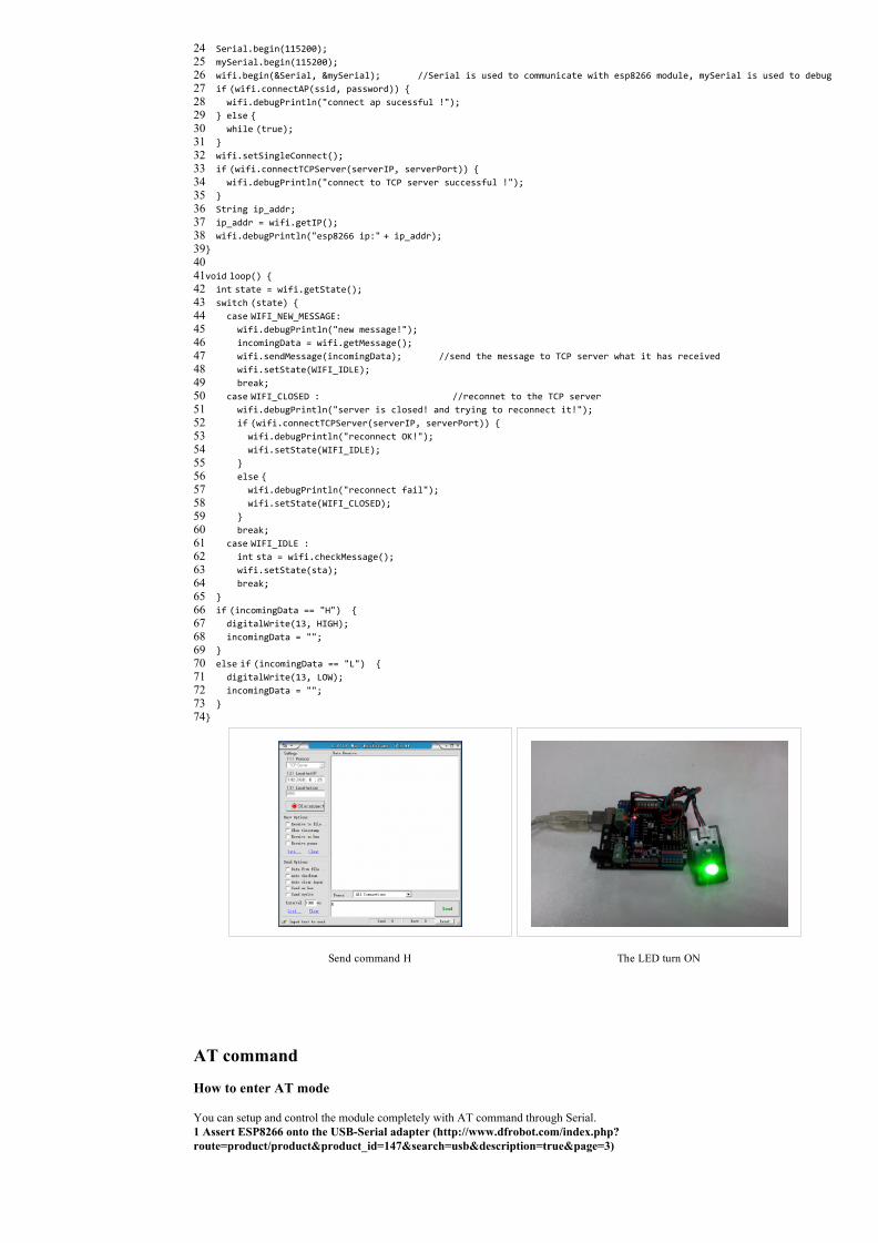
This is a little application which is built on the 4.1.2 2 TCP_Client_Single trail, if you have finished that part, you could upload thesketch below, and send commands "H","L" to open up or turn off it on your computer. And since that almost every Arduino card has aLED built on board, connected with D13, so in the sketch, I will use it as the target LED.
?1234567891011121314151617181920212223
// this example use esp8266 to connect to an Access Point and connect to SINGLE TCP Server which is at the same subnet// such as the esp8266 is is 192.168.1.3, and the server ip is 192.168.1.1 ,then esp8266 can connect to the server //Then connect a LED on Digital pin13, and open the software on PC_TCP server, send command to control the LED state://send "H" to turn ON LED; send "L" to turn OFF LED #include "esp8266.h"#include "SoftwareSerial.h" #define ssid "test" // you need to change it#define password "12345678" #define serverIP "192.168.1.1"#define serverPort "8081"int ledPin = 13;String incomingData = ""; Esp8266 wifi;SoftwareSerial mySerial(10, 11); // RX, TX void setup() pinMode(ledPin, OUTPUT); delay(2000); // it will be better to delay 2s to wait esp8266 module OK
242526272829303132333435363738394041424344454647484950515253545556575859606162636465666768697071727374
Serial.begin(115200); mySerial.begin(115200); wifi.begin(&Serial, &mySerial); //Serial is used to communicate with esp8266 module, mySerial is used to debug if (wifi.connectAP(ssid, password)) wifi.debugPrintln("connect ap sucessful !"); else while (true); wifi.setSingleConnect(); if (wifi.connectTCPServer(serverIP, serverPort)) wifi.debugPrintln("connect to TCP server successful !"); String ip_addr; ip_addr = wifi.getIP(); wifi.debugPrintln("esp8266 ip:" + ip_addr); void loop() int state = wifi.getState(); switch (state) case WIFI_NEW_MESSAGE: wifi.debugPrintln("new message!"); incomingData = wifi.getMessage(); wifi.sendMessage(incomingData); //send the message to TCP server what it has received wifi.setState(WIFI_IDLE); break; case WIFI_CLOSED : //reconnet to the TCP server wifi.debugPrintln("server is closed! and trying to reconnect it!"); if (wifi.connectTCPServer(serverIP, serverPort)) wifi.debugPrintln("reconnect OK!"); wifi.setState(WIFI_IDLE); else wifi.debugPrintln("reconnect fail"); wifi.setState(WIFI_CLOSED); break; case WIFI_IDLE : int sta = wifi.checkMessage(); wifi.setState(sta); break; if (incomingData == "H") digitalWrite(13, HIGH); incomingData = ""; else if (incomingData == "L") digitalWrite(13, LOW); incomingData = "";
Send command H
The LED turn ON
AT command
How to enter AT mode
You can setup and control the module completely with AT command through Serial. 1 Assert ESP8266 onto the USBSerial adapter (http://www.dfrobot.com/index.php?route=product/product&product_id=147&search=usb&description=true&page=3)
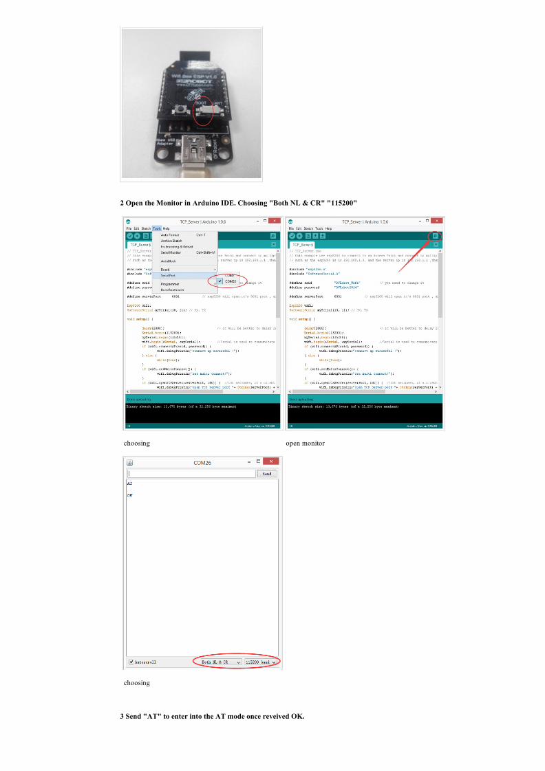
2 Open the Monitor in Arduino IDE. Choosing "Both NL & CR" "115200"
choosing
open monitor
choosing
3 Send "AT" to enter into the AT mode once reveived OK.
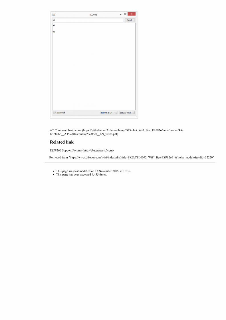
AT Command Instruction (https://github.com/Arduinolibrary/DFRobot_Wifi_Bee_ESP8266/raw/master/4AESP8266__AT%20Instruction%20Set__EN_v0.23.pdf)
Related link
ESP8266 Support Forums (http://bbs.espressif.com)
Retrieved from "https://www.dfrobot.com/wiki/index.php?title=SKU:TEL0092_WiFi_BeeESP8266_Wirelss_module&oldid=32229"
This page was last modified on 13 November 2015, at 16:36.This page has been accessed 4,455 times.