Embed Size (px)
Citation preview
8/8/2019 Skylab Experiments. Volume 6 Mechanics
http://slidepdf.com/reader/full/skylab-experiments-volume-6-mechanics 1/40
Source of Acquisition
NAS A Washington, D. C.
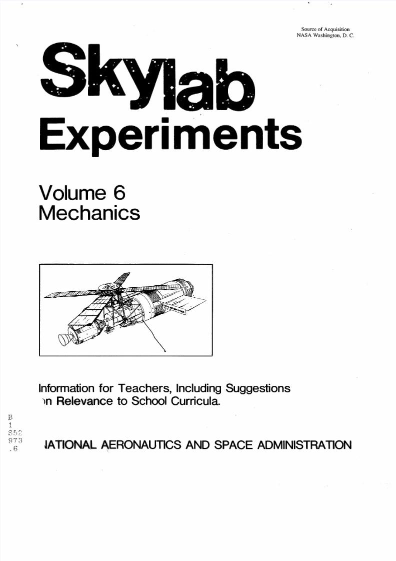
ExperimentsVolume 6Mechanics
Information for Teachers, Including SuggestionsIn Relevance to School Curricula.
.-
JATIONAL AERONAUTICS AND SPACE ADMINISTRATION
8/8/2019 Skylab Experiments. Volume 6 Mechanics
http://slidepdf.com/reader/full/skylab-experiments-volume-6-mechanics 2/40
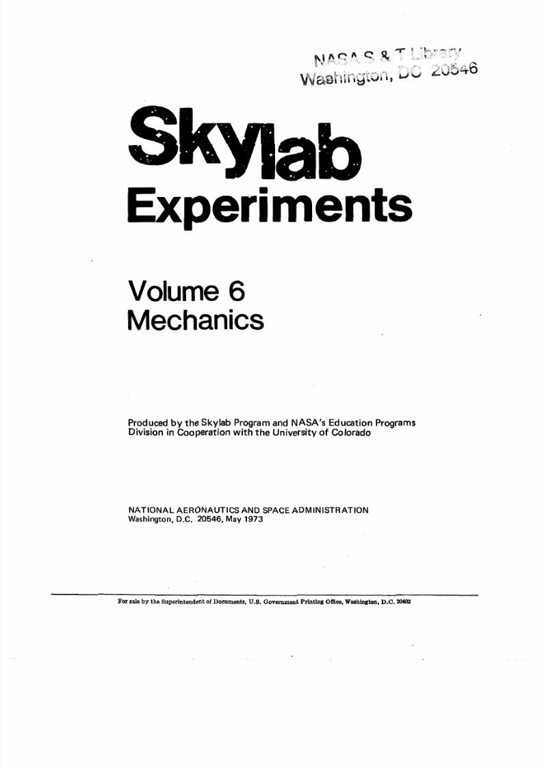
Experiments
Volume 6
Mechanics
Produced by the Skylab Program and NASA's Education ProgramsDivision in Cooperation with the University of Colorado
NATIONAL AERONAUTICS AND SPACE ADMINISTRATIONWashington, D.C. 20546, May 1973
For snle by the Superintendent of Documents, U.8.aovernment Printing OWce, Washington, D.C. 2M02
8/8/2019 Skylab Experiments. Volume 6 Mechanics
http://slidepdf.com/reader/full/skylab-experiments-volume-6-mechanics 3/40
PREFACE
Characteristically, new scientific knowledge reaches general application in classrooms years
after i t has been obtained. This long delay stems, t o a large extent, from a lack of awareness
tha t information is available and that it has relevance to secondary school curricula. To
accelerate this process, the National Aeronautics and Space Administration has prepared a
series of documents concerning Skylab experiments to apprise the educational community
in detail of the investigations being conducted in the Skylab Program, and the types ofinformation being produced.
The objective is not to introduce the Skylab Program as a subject in th e classroom, but
rather t o make certain that the educational community is aware of the information being
generated and that it will be available for use. Readers are urged to use these books as an aid
in planning development of future curriculum supplement material to make the most
appropriate use of this source of scientific knowledge.
National Aeronautics and Space Administration
Washington,D. C. 20546
May 1973
8/8/2019 Skylab Experiments. Volume 6 Mechanics
http://slidepdf.com/reader/full/skylab-experiments-volume-6-mechanics 4/40
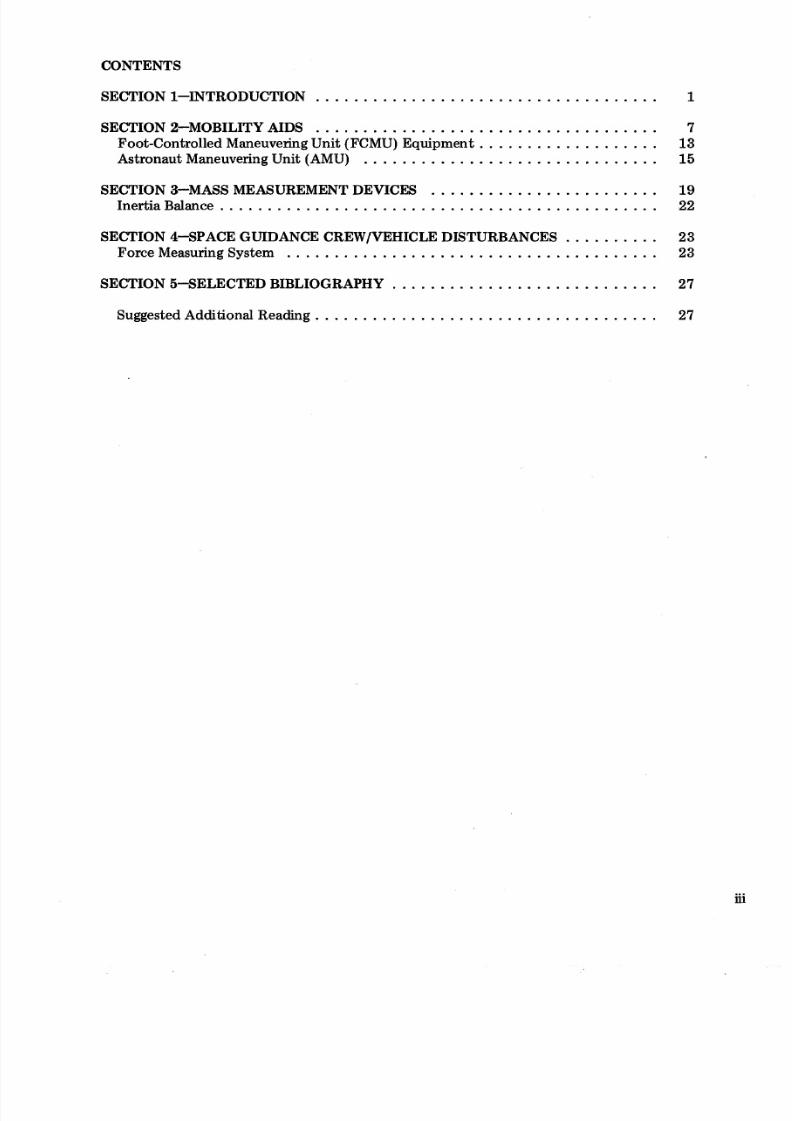
CONTENTS
SECTION 1-INTRODUCTION . . . . . . . . . . . . . . . . . . . . . . . . . . . . . . . . . . . . 1SECTION 2-MOBILITY AIDS . . . . . . . . . . . . . . . . . . . . . . . . . . . . . . . . . . . . 7
Foot-Controlled Maneuvering Unit (FCMU) Equipment . . . . . . . . . . . . . . . . . . . 13Astronaut Maneuvering Unit (AMU) . . . . . . . . . . . . . . . . . . . . . . . . . . . . . . . 15
SECTION 3-MASS MEASUREMENT DEVICES . . . . . . . . . . . . . . . . . . . . . . . . 19Inertia Balance . . . . . . . . . . . . . . . . . . . . . . . . . . . . . . . . . . . . . . . . . . . . . . 22
SECTION 4-SPACE GUIDANCE CREWIVEHICLE DISTURBANCES . . . . . . . . . . 23Force Measuring System . . . . . . . . . . . . . . . . . . . . . . . . . . . . . . . . . . . . . . . 23
SECTION 5-SELECTED BIBLIOGRAPHY . . . . . . . . . . . . . . . . . . . . . . . . . . . . 27
. . . . . . . . . . . . . . . . . . . . . . . . . . . . . . . . . . . .uggested Additional Reading 27
8/8/2019 Skylab Experiments. Volume 6 Mechanics
http://slidepdf.com/reader/full/skylab-experiments-volume-6-mechanics 5/40
INTRODUCTION
The Skylab EducaZion Program
This year the United States' first manned scientific space station, Skylab, was launched into
orbit to be the facility in which successive crews of astronauts can perform more than 270
scientific investigations in a variety of fields of interest. These investigations can be divided
into four categories: physical sciences, biomedical sciences, earth applications, and spaceapplications.
The Skylab Program will produce inforpation that will enhance present scientific
knowledge and perhaps extend the frontiers of knowledge on subjects ranging from the
nature of the universe to the structure of the single human cell. It is the objective of the
National Aeronautics and Space Administration that the knowledge derived from the Skylab
Program's investigations be made available to the educational community for applications to
high school education at the earliest possible date.
For this reason, the Skylab Education Program was created to assure that maximum
educational benefits are obtained from the Skylab effort, documentation of Skylabactivities is adequately conducted, and understanding of scientific developments is
enhanced.
This document, one of several volumes prepared as part of the Skylab Education Program,
has the dual purpose of (1) nforming high school teachers about the scientific investigations
performed in Skylab, and (2) enabling teachers to evaluate the educational benefits the
Skylab Program can provide.
These books will define the objectives of each experiment, describe the scientific
background on which the experiment is based, outline the experimental procedures, and
indicate the types of data anticipated.
In preparing these documents an attempt has been made to illustrate relationships between
the planned Skylab investigations and high school science topics. Concepts for classroom
activities have been included that use specific elements of Skylab science as focal points for
demonstrations of selected subjects. In some areas these address current curriculum topics
by providing practical applications of relatively familiar, but sometimes abstract principles;
in other areas the goal is to provide an introduction to phenomena rarely addressed in high
school science curricula.
It is the hope of the National Aeronautics and Space Administration that these volumes will
assist the high school teacher in recognizing the educational value of the information
resulting from the Skylab Program which is available to all who desire to make use of it.
Application
Readers are asked to evaluate the investigations described herein in terms of the scientific
subjects taught in secondary schools. The related curriculum topics identified should serve
as suggestions for the application of Skylab Program-generated information to classroom
activities. As information becomes available from the Skylab Program, announcements will
be distributed to members of the educational community on the NASA Educational
iv
8/8/2019 Skylab Experiments. Volume 6 Mechanics
http://slidepdf.com/reader/full/skylab-experiments-volume-6-mechanics 6/40
Programs Division mailing list. To obtain these announcements send name, title, and full
school mailing list (including zip code) to:
National Aeronautics and Space Administration
Washington, D.C. 20546
Mail Code FE
Some of the aspects of space flight which because of the near weightless environment
significantly restrict solutions to such problems as mass transfer, astronaut mobility, and
mass measurement, are discussed in this volume.
In Section I the reader is introduced to a concept of weight, which while i t departs from the
classical physics view provides a concept for weight that satisfies both the laws of mechanics
and our sensible notions of weight.
The related Skylab investigations are described in detail in Sections 2 through 4. The
relationship between the experimental goals and the scientific basis for the experimentalhardware and protocols are discussed.
Wherever possible, relationships have been developed between the Skylab scientific
ihvestigations and classroom curricula and activities. These relationships are discussed in
each section as appropriate.
Acknowledgments
Valuable guidance was provided in the area of relevance to high school curricula by Dr.
James R. Wailes, Professor of Science Education, School of Education, University of
Colorado; assisted by Mr. Kenneth G. Jacknicke, Research Associate on leave from the
University of Alberta, Edmonton, Alberta, Canada; Mr Russel Yeany, Jr., ResearchAssociate, on leave from the Armstrong School District, Pennsylvania; and Dr. Harry Herzer
and Mr. Duane Houston, Education and Research Foundation, Oklahoma State University.
The Skylab Program
The Skylab orbiting space station will serve as a workshop and living quarters for astronauts
as they perform investigations in the following broad categories: physical sciences,
biomedical sciences, Earth applications, and space applications.
The spacecraft will remain operational for an eight-month period, manned on three
occasions and unmanned during intervening periods of operation. Each manned flight will
have a crew of three different astronauts. The three flights are planned for durations of one
month, two months, and two months, respectively.
A summary of objectives of each of the categories of investigation follows.
Physical Science
Observations free of filtering and obscuring effects of the Earth's atmosphere will be
performed to increase man's knowledge of (1) he sun and of its importance t o Earth and
mankind, and (2) the radiation and particulate environment in near-Earth space and the
sources from which these phenomena emanate.
8/8/2019 Skylab Experiments. Volume 6 Mechanics
http://slidepdf.com/reader/full/skylab-experiments-volume-6-mechanics 7/40
Biomedical Science
Observations under conditions different from those on Earth will be made to increase man's
knowledge of the biological functions of living organisms, and of the capabilities of man tolive and work for prolonged periods in the orbital environment.
Earth Applications
Techniques will be developed for observing from space and interpreting (1) Earth
phenomena in the areas of agriculture, forestry, geology, geography,air and water pollution,
land use and meteorology, and (2) the influence of man on these elements.
Space Applications
Techniques for adapting to and using the unique properties of space flight will be developed.
The Skylab Spacecraft
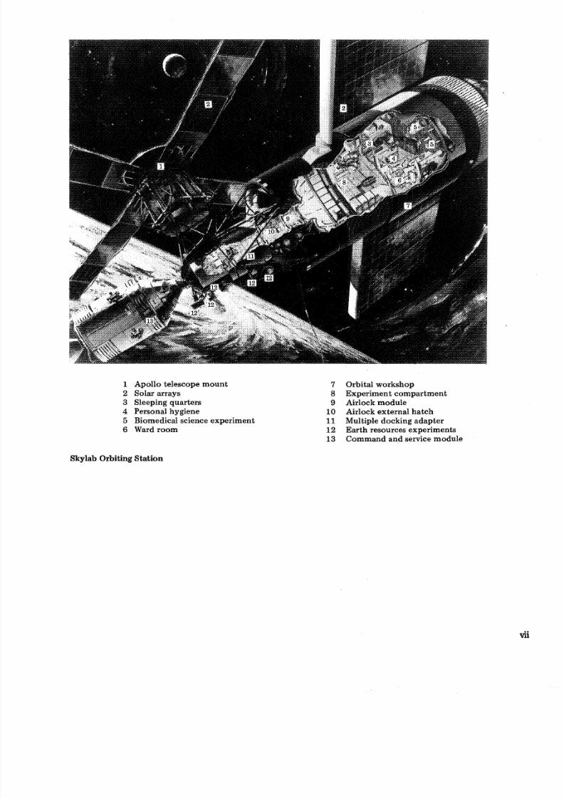
The.Skylab cluster contains five modules (see illustration).
1) The orbital workshop is the prime living and working area for the Skylab crews. Itcontains living and sleeping quarters, food preparation and eating areas, and personal
hygiene equipment. It also contains the equipment for the biomedical science experirhents
and for some of the physical science and space applications experiments. Solar arrays for
generation of electrical power are mounted outside this module.
2) The airlock module contains the airlock through which suited astronauts emerge toperform activities outside the cluster. It also contains equipment used t o control the
cluster's internal environment and the workshop electrical power and communications
systems.
3) The multiple docking adapter provides the docking port for the arriving and departingcommand and service modules, and contains the control center for the telescope mount
experiments and systems. I t also houses the Earth applications experiments and materials
science and technology experiments.
4) The Apollo telescope mount houses a sophisticated solar observatory b.aving eight
telescopes observing varying wavelengths from visible, through near and far ultraviolet, toX-ray. I t contains the gyroscopes and computers by which the flight attitude of Skylab iscontrolled. Solar arrays mounted on this module generate about half of the electrical power
available to the cluster.
5) The command and service module is the vehicle in which the crew travels from Earth toSkylab and back to Earth, and in which supplies are conveyed to Skylab, and experiment
specimens and film are returned t o Earth.
Skylab will fly in a circular orbit about 436 kilometers (235 nautical miles) above the
surface of the Earth, and is planned to pass over any given point within latitudes 50" north
and 50" south of the equator every five days. In its orbital configuration, Skylab will weigh
over 91,000 kilograms (200,000 pounds) and will contain nearly 370 cubic meters (13,000
cubic feet) for work and living space (about th'e size of a three bedroom house).
vi
8/8/2019 Skylab Experiments. Volume 6 Mechanics
http://slidepdf.com/reader/full/skylab-experiments-volume-6-mechanics 8/40
1 Apollo telescope mount
2 Solar arrays3 Sleeping quarters
4 Personal hygiene
5 Biomedical science experiment
6 Ward room
7 Orbital workshop
8 Experiment compartment9 Airlock module
10 Airlock external hatch
11 Multiple docking adapter
12 Earth resources experiments
13 Command and service module
Skylab Orbiting Station
8/8/2019 Skylab Experiments. Volume 6 Mechanics
http://slidepdf.com/reader/full/skylab-experiments-volume-6-mechanics 9/40
Section 1
Introduction
8/8/2019 Skylab Experiments. Volume 6 Mechanics
http://slidepdf.com/reader/full/skylab-experiments-volume-6-mechanics 10/40
EXPERIMENTBACKGROUND
In physics, the study of the effects of forces upon bodies at
rest or in motion is called mechanics. In general, the term
may be applied whether the phenomena studied involve
fluids, gases, or solids. Practically speaking, the term is
restricted to rigid or elastic properties of solid materials. The
science of mechanics is sometimes subdivided into Statics,Kinematics, and Kinetics. Modern usage favors the term
"dynamics" reserving the term "mechanics" for the more
practical phases of the field (machinery, building, etc).
The idea that the forces applied to a body control the motion
of the body was described clearly for the first time by Sir
Isaac Newton (1642-1727). In describing this motion,
Newton postulated three laws that are now accepted as being
universally true. Newton's three laws of motion may be
stated as:
First L a w a body continues in its state of rest or uniformmotion unless acted upon by an unbalanced force.
Second Law-the acceleration of a body acted upon by an
unbalanced force is directly proportional to the unbalanced
force, inversely proportional to the mass of the body, and in
the direction of the unbalanced force.
Third Law-for every force or action there is an equal and
opposite force or action.
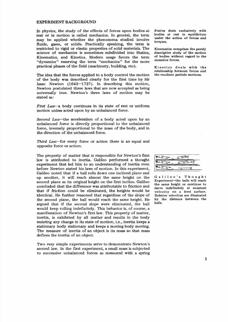
The property of matter that is responsible for Newton's first
law is attributed to inertia. Galileo performed a thoughtexperiment that led him to an understanding of inertia even
before Newton stated his laws of motion. In this experiment,
Galileo noted that if a ball rolls down one inclined p1ar.e and
up another, it will reach almost the same height on the
second plane as its original height on the first incline. Galileo
concluded that the difference was attributable t o friction and
that if friction could be eliminated, the heights would be
identical. He further reasoned that regardless of the slope of
the second plane, the ball would reach the same height. He
argued that if the second slope were eliminated, the ball
would keep rolling indefinitely. This behavior is, of course, a
manifestation of Newton's first law. This property of matter,
inertia, is exhibited by all matter and results in the body
resisting any change in its state of motion, i.e., inertia keeps a
stationary body stationary and keeps a moving body moving.
The measure of inertia of an object is its mass so that mass
defines the inertia of an object.
Statics deals exclusively with
bodies at rest in equilibrium
under the action of forces and
torques.
Kinematics comprises the purely
descriptive study of the motionof bodies without regard to the
causative forces.
K i n e t i c s d e a l s wi th th e
relationship between forces and
the resultant particle motions.
G a l i l e o ' s T h o u g h t
Experiment-the balls will reach
the same height or continue to
move indefinitely at constant
velocity on a level surface.
Relative velocities are illustrated
by the distance between the
balls.
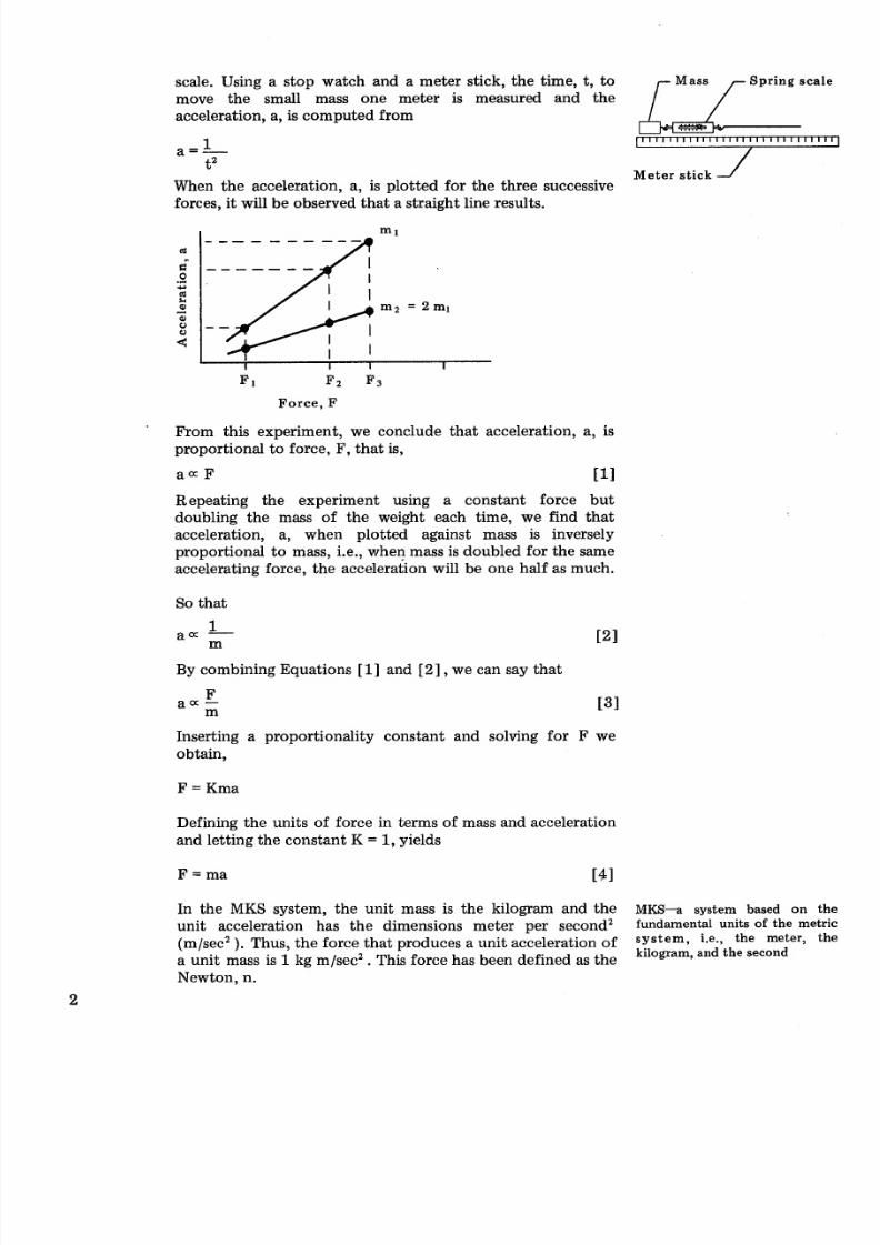
Two very simple experiments serve to demonstrate Newton's
second law. In the first experiment, a small mass is subjected
to successive unbalanced forces as measured with a spring
8/8/2019 Skylab Experiments. Volume 6 Mechanics
http://slidepdf.com/reader/full/skylab-experiments-volume-6-mechanics 11/40
scale. Using a stop watch and a meter stick, the time, t, to Spring scale
move the small mass one meter is measured and the
r Mass/
acceleration, a, is computed from /- b
1a = -t2
Meter stickWhen the acceleration, a, is plotted for the three successive
forces, i t will be observed that a straight line results.
I I I IF 1 F2 F3
Force, F
From this experiment, we conclude that acceleration, a, is
proportional to force, F, that is,
a a F 111Repeating the experiment using a constant force but
doubling the mass of the weight each time, we find that
acceleration, a, when plotted against mass is inversely
proportional to mass, i.e., when mass is doubled fo r the same
accelerating force, the acceleration will be one half as much.
So that
1a a -By combining Equations [ I ] and [ 2] , we can say that
Inserting a proportionality constant and solving for F we
obtain,
F = Kma
Defining the units of force in terms of mass and accelerationand letting the constant K = 1,yields
In the MKS system, the unit mass is the kilogram and the MKS-a system based on th
unit acceleration has the dimensions meter per second2 fundamental units of the metri
(m/sec2 . Thus, th e force tha t produces a unit acceleration of i.e-* the th
a unit mass is 1 kg m/sec2. This force has been defined as thekilogram, and the second
Newton, n.
8/8/2019 Skylab Experiments. Volume 6 Mechanics
http://slidepdf.com/reader/full/skylab-experiments-volume-6-mechanics 12/40
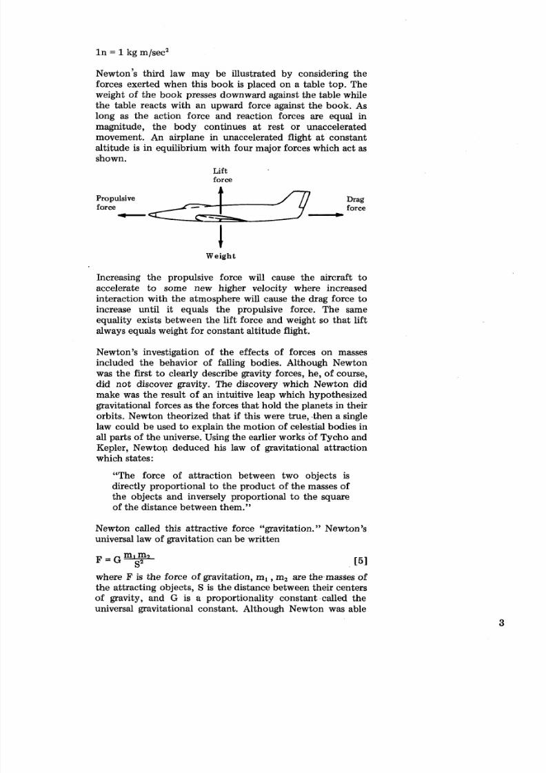
~ew to n ' s hird law may be illustrated by considering the
forces exerted when this book is placed on a table top. The
weight of the book presses downward against the table while
the table reacts with an upward force against the book. As
long as the action force and reaction forces are equal in
magnitude, the body continues at rest or unacceleratedmovement. An airplane in unaccelerated flight at constant
altitude is in equilibrium with four major forces which act as
shown.
Lift
force
Propulsive Drag
force force- -Weight
Increasing the propulsive force will cause the aircraft to
accelerate to some new higher velocity where increased
interaction with the atmosphere will cause the drag force to
increase until it equals the propulsive force. The same
equality exists between the lift force and weight so tha t lift
always equals weight for constant altitude flight.
Newton's investigation of the effects of forces on masses
included the behavior of falling bodies. Although Newton
was the first to clearly describe gravity forces, he, of course,
did not discover gravity. The discovery which Newton didmake was the result of an intuitive leap which hypothesized
gravitational forces as the forces that hold the planets in their
orbits. Newton theorized that if this were true, .then a single
law could be used to explain the motion of celestial bodies in
all parts of the universe. Using the earlier works of Tycho and
Kepler, new to^ deduced his law of gravitational attraction
which states:
"The force of attraction between two objects is
directly proportional to the product of the masses of
the objects and inversely proportional to the square
of the distance between them."
Newton called this attractive force "gravitation." Newton's
universal law of gravitation can be written
where F is the force of gravitation, m, ,m2 are the,masses of
the attracting objects, S is the distance between their centers
of gravity, and G is a proportionality constant.called the
universal gravitational constant. Although Newton was able
8/8/2019 Skylab Experiments. Volume 6 Mechanics
http://slidepdf.com/reader/full/skylab-experiments-volume-6-mechanics 13/40
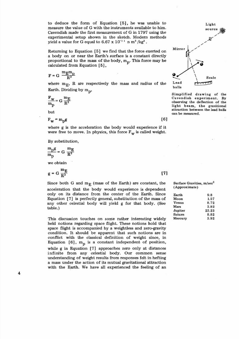
to deduce the form of Equation [5] , he was unable to
measure the value of G with the instruments available to him.
Cavendish made the first measurement of G in 1797 using the
experimental setup shown in the sketch. Modern methods
yield a value for G equal to 6.67 x lo -' ' n m2 /kg2.
Returning to Equation [5] we find that the force exerted on
a body on or near the Earth's surface is a constant directlyproportional to the mass of the body, m This force may be
calculated from Equation 151,P
where m ~ , are respectively the mass and radius of the
Earth. Dividing by mp,
but
where g is the acceleration the body would experience if it
were free to move. In physics, this force Fw is called weight.
By substitution,
we obtain
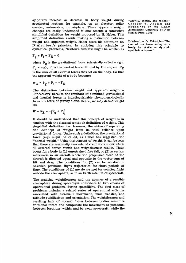
Since both G and r n ~mass of the Earth) are constant, the
acceleration that the body would experience is dependent
only on its distance from the center of the Earth. Since
Equation [7] is perfectly general, substitution of the mass of
any other celestial body will yield g for that body. (See
table.)
This discussion touches on some rather interesting widely
held notions regarding space flight. These notions hold that
space flight is accompanied by a weightless and zero-gravity
condition. It should be apparent that such notions are in
conflict with the classical definition of weight since, in
Equation [6] , m is a constant independent of position,P
while g in Equation [7 ] approaches zero only at distances
infinite from any celestial body. Our common sense
understanding of weight results from responses felt in hefting
a mass under the action of its mutual gravitational attraction
with the Earth. We have all experienced the feeling of an
Light
source
/
\ Scale
Lead
balls -implified drawing of the
Cavendish experiment. Byobserving the deflection of the
light beam, the gravitiona
attraction between the lead balls
can be measured.
Surface Gravities, m/sec2
(Approxiinate)
Earth 9.8
Moon 1.57
Venus 8.72
Mars 3.82
Jupiter 23.23
Saturn 8.82
Mercury 3.92
8/8/2019 Skylab Experiments. Volume 6 Mechanics
http://slidepdf.com/reader/full/skylab-experiments-volume-6-mechanics 14/40
apparent increase or decrease in body weight during
accelerated motion; for example, on an elevator, roller
coaster, automobile, or airplane. These apparent weight
changes are easily understood if one accepts a somewhat
simplified definition for weight proposed by H. Haber. This
simplified definition avoids making a distinction between
weight and apparent weight. Haber bases his definition on
D'Alemb er t' s principle. In applying this principle to
dynamical problems, Newton's first law might be written as
F + F i + F E = Og
where F is the gravitational force (classically called weightg
Fg = mg) , Fi is the inertial force defined by F = ma, and FE
is the sum of all external forces that act on the body. So that
the apparent weight of a body becomes
The distinction between weight and apparent weight is
unnecessary because the resultant of combined gravitational
and inertial forces is indistinguishable phenomenologically
from the force of gravity alone. Hence, we may define weight'
as:
It should be understood that this concept of weight is in
conflict with the classical textbook definition of weight. This
simplified definition has, however, the virtue of separating
t h e concept of weight from its total reliance upon
gravitational forces. Under such a definition, the gravitational
force (mg) might be called, as Haber has suggested, the
"normal weight." Using this concept of weight, it can be seen
that there are essentially two sets of conditions under which
all external forces vanish and weightlessness results. These
occur for a body in (1) unrestrained free fall, or (2) in certain
maneuvers in an aircraft where the propulsive force of the
aircraft is directed equal and opposite to the vector sum of
lift and drag. The conditions for (2) can be satisfied in
so-called parabolic flight trajectories for short periods of
time. The conditions of (1) are always met for coasting flight
outside the atmosphere, as in an Earth satellite or spacecraft.
The resulting weightlessness and the absence of a sensible
atmosphere during spaceflight contribute to two classes of
operational problems during spaceflight. The first class of
problems includes a related series of operational activities
associated with astronaut movement, mass transfer, and
attitude stabilizaiton and orientation. The weightlessness and
resulting lack of normal forces between bodies minimize
frictional forces and complicate the movement of personnel
between locations within and between spacecraft, while the
"Gravity, Inertia, and Weight,"
C h a p t e r 9 , P h ys ics an dM e d i c i n e s o f th e U p pe rAtmosphere University of New
Mexico Press, 1952.
D 'Ale mb er t 's Principle-"The
sum of the forces acting on abody in static or dynamic
equilibrium is zero."
8/8/2019 Skylab Experiments. Volume 6 Mechanics
http://slidepdf.com/reader/full/skylab-experiments-volume-6-mechanics 15/40
absence of an atmosphere negates the use of traditional air
foils to generate steering forces. This operational problem
will require the design, development, and evaluation of
specialized propulsion and steering systems for efficient
transfer of men and materials in the space environment.
The second class of operational problems is exemplified by
the necessity to measure food intake, waste products, andbody weight, and t o perform a variety of other mass
measurements and related activities. The weightlessness
inherent in the environment of space makes the measurement
of mass by conventional mass balance and force balance
systems impossible and requires the design, development, and
evaluation of sensitive, and accurate mass measurement
devices.
The Skylab experimental program includes a variety of
experiments and experimental hardware for evaluation of
techniques to accomplish the required tasks. These hardware,
protocols, and expected results are discussed in the followingsections.

8/8/2019 Skylab Experiments. Volume 6 Mechanics
http://slidepdf.com/reader/full/skylab-experiments-volume-6-mechanics 16/40
Section 2Mobility Aids
8/8/2019 Skylab Experiments. Volume 6 Mechanics
http://slidepdf.com/reader/full/skylab-experiments-volume-6-mechanics 17/40
EXPERIMENT BACKGROUND
The astronaut maneuvering unit (backpack assembly) and
foot-controlled maneuvering unit are included in the Skylab
scientific program to explore a variety of techniques for
achieving astronaut maneuverability and stability in the
weightless environment of space.
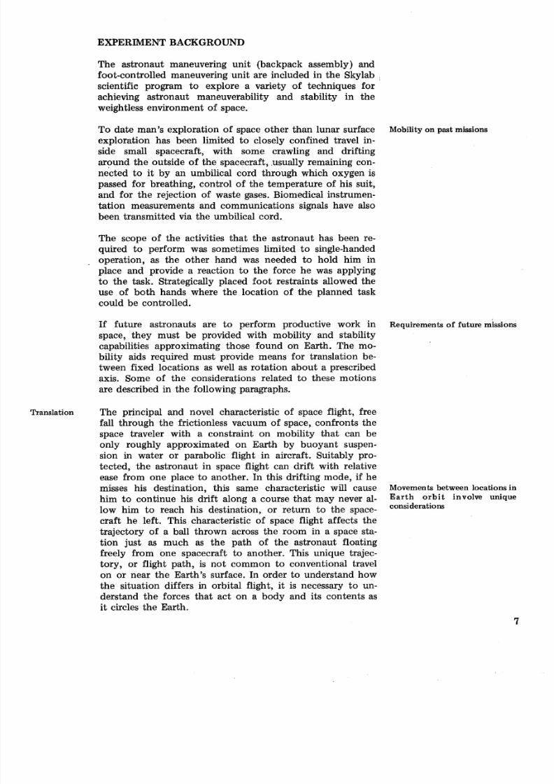
To date man's exploration of space other than lunar surface Mobility on past missions
exploration has been limited to closely confined travel in-
side small spacecraft, with some crawling and drifting
around the outside of the spacecraft, .usually remaining con-
nected to it by an umbilical cord through which oxygen is
passed for breathing, control of the temperature of his suit,
and for the rejection of waste gases. Biomedical instrumen-
tation measurements and communications signals have also
been transmitted via the umbilical cord.
The scope of the activities that the astronaut has been re-
quired to perform was sometimes limited to single-handed
operation, as the other hand was needed to hold him inplace and provide a reaction to the force he was applying
to the task. Strategically placed foot restraints allowed the
use of both hands where the location of the planned task
could be controlled.
If future astronauts are to perform productive work in Requirements of future missions
space, they must be provided with mobility and stability
capabilities approximating those found on Earth. The mo-
bility aids required must provide means for translation be-
tween fixed locations as well as rotation about a prescribed
axis. Some of the considerations related to these motions
are described in the following paragraphs.
Translation The principal and novel characteristic of space flight, free
fall through the frictionless vacuum of space, confronts the
space traveler with a constraint on mobility that can be
only roughly approximated on Earth by buoyant suspen-
sion in water or parabolic flight in aircraft. Suitably pro-
tected, the astronaut in space flight can drift with relative
ease from one place to another. In this drifting mode, if he
misses his destination, this same characteristic will cause Movements between locationsin
him to continue his drift along a course that may never al- Earth orbit involve unique
low him t o reach his destination, or return to the space-
craft he left. This characteristic of space flight affects thetrajectory of a ball thrown across the room in a space sta-
tion just as much as the path of the astronaut floating
freely from one spacecraft to another. This unique trajec-
tory, or flight path, is not common to conventional travel
on or near the Earth's surface. In order to understand how
the situation differs in orbital flight, it is necessary to un-
derstand the forces that act on a body and its contents as
it circles the Earth.
8/8/2019 Skylab Experiments. Volume 6 Mechanics
http://slidepdf.com/reader/full/skylab-experiments-volume-6-mechanics 18/40
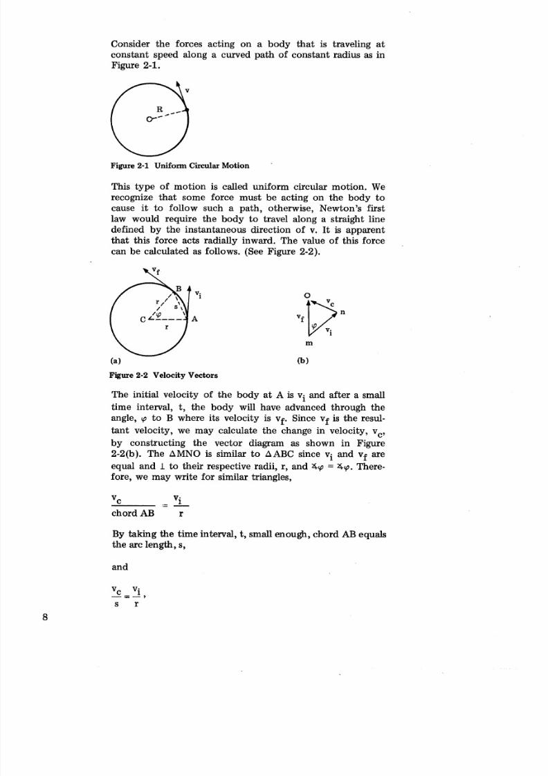
Consider the forces acting on a body that is traveling at
constant speed along a curved path of constant radius as in
Figure 2-1.
Figure 2-1 Uniform Circular Motion
This type of motion is called uniform circular motion. We
recognize that some force must be acting on the body to
cause it to follow such a path, otherwise, Newton's first
law would require the body to travel along a straight line
defined by the instantaneous direction of v. I t is apparent
that this force acts radially inward. The value of this force
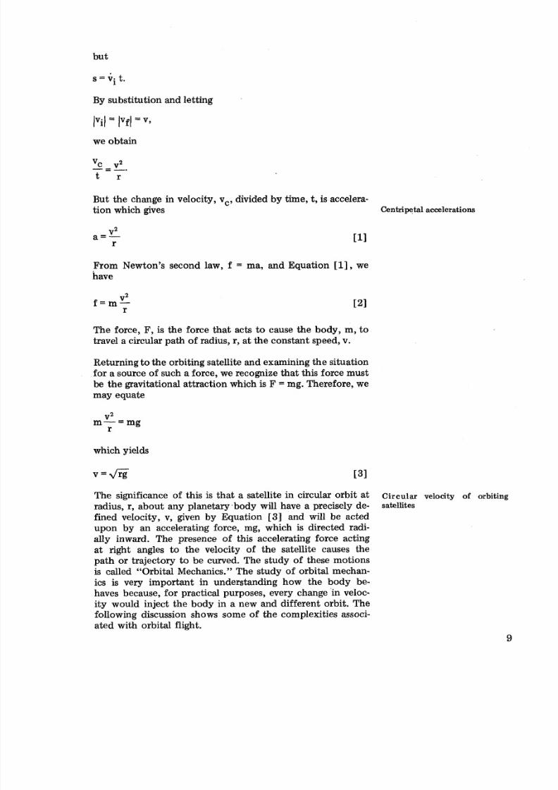
can be calculated as follows. (See Figure 2-2).
Figure 2-2 Velocity Vectors
The initial velocity of the body a t A is vi and after a small
time interval, t, the body will have advanced through the
angle, cp to B where its velocity is vf. Since vf is the resul-
tant velocity, we may calculate the change in velocity, vc,
by constructing the vector diagram as shown in Figure
2-2(b). The AMNO is similar to AABC since vi and vf are
equal and 1 to their respective radii, r, and 4cp = 4cp. There-
fore, we may write for similar triangles,
vc .- Vi- -
chord AB r
By taking the time interval, t, small enough, chord AB equals
the arc length, s,
and
8/8/2019 Skylab Experiments. Volume 6 Mechanics
http://slidepdf.com/reader/full/skylab-experiments-volume-6-mechanics 19/40
By substitution and letting
we obtain
But the change in velocity, vc, divided by time, t, is accelera-
tion which gives Ce nt ri ~t al ccelerations
From Newton's second law, f = ma, and Equation [I], wehave
The force, F, is the force that acts to cause the body, m, to
travel a circular path of radius, r, a t the constant speed, v.
Returning to the orbiting satellite and examining the situation
for a source of such a force, we recognize that this force must
be the gravitational attraction which is F = mg. Therefore, we
may equate
which yields
The significance of this is tha t a satellite in circular orbit a t Circular velocity of orbiting
radius, r, about any planetary-body will have a precisely de- satellites
fined velocity, v, given by Equation [3 ] and will be acted
upon by an accelerating force, mg, which is directed radi-ally inward. The presence of this accelerating force acting
at right angles to the velocity of the satellite causes the
path or trajectory to be curved. The study of these motions
is called "Orbital Mechanics." The study of orbital mechan-
ics is very important in understanding how the body be-
haves because, for practical purposes, every change in veloc-
ity would inject the body in a new and different orbit. The
following discussion shows some of the complexities associ-
ated with orbital flight.
8/8/2019 Skylab Experiments. Volume 6 Mechanics
http://slidepdf.com/reader/full/skylab-experiments-volume-6-mechanics 20/40
Orbital
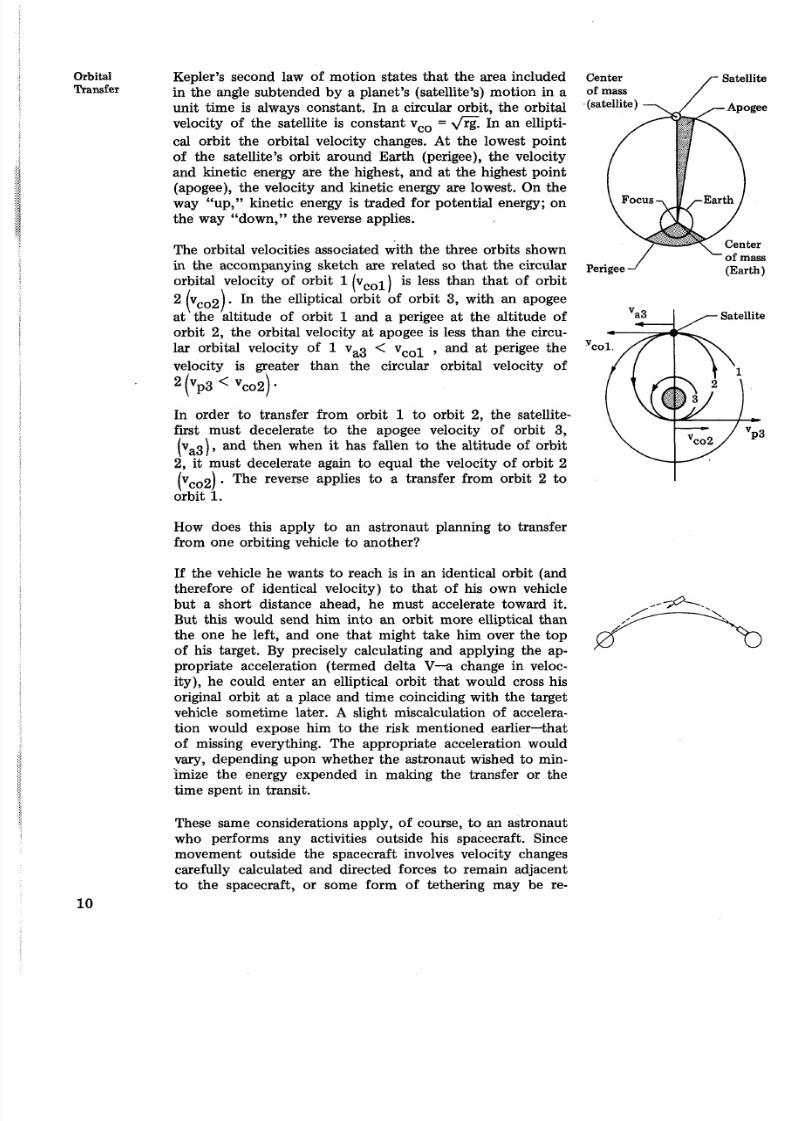
TransferKepler's second law of motion states tha t the area included Center
in the angle subtended by a planet's (satellite's) motion in a of mass
unit time is always constant. In a circular orbit, the orbital
velocity of the satellite is constant vco = .\/rg. In an ellipti-
cal orbit the orbital velocity changes. At the lowest point
of the satellite's orbit around Earth (perigee), the velocity
and kinetic energy are the highest, and at the highest point
(apogee), the velocity and kinetic energy are lowest. On theway "up," kinetic energy is traded for potential energy; on
the way "down," the reverse applies.
The orbital velocities associated with the three orbits shown
in the accompanying sketch are related so that the circular Perigee
orbital velocity of orbit 1 vol) is less than that of orbit
2 (vCo2). In the elliptical orbit of orbit 3, with an apogee
at the altitude of orbit 1 and a perigee at the altitude of
orbit 2, the orbital velocity at apogee is less than the circu-
lar orbital velocity of 1 va3 < vcol , and at perigee the 'co
velocity is greater than the circular orbital velocity of
(Yp3 < vc02) .
In order to transfer from orbit 1 to orbit 2, the satellite-
first must decelerate to the apogee velocity of orbit 3,
(va3), and then when it has fallen to the altitude of orbit
2, it must decelerate again to equal the velocity of orbit 2
(vCo2). The reverse applies to a transfer from orbit 2 to
orbit 1.
How does this apply to an astronaut planning to transfer
from one orbiting vehicle to another?
If the vehicle he wants to reach is in an identical orbit (and
therefore of identical velocity) to that of his own vehicle
but a short distance ahead, he must accelerate toward it. c+But this would send him into an orbit more elliptical than
the one he left, and one that might take him over the top
of his target. By precisely calculating and applying the ap-
propriate acceleration (termed delta V--a change in veloc-
ity), he could enter an elliptical orbit that would cross his
original orbit at a place and time coinciding with the target
vehicle sometime later. A slight miscalculation of accelera-
tion would expose him to the risk mentioned earlier-that
of missing everything. The appropriate acceleration wouldvary, depending upon whether the astronaut wished to min-
imize the energy expended in making the transfer or the
time spent in transit.
These same considerations apply, of course, to an astronaut
who performs any activities outside his spacecraft. Since
movement outside the spacecraft involves velocity changes
carefully calculated and directed forces to remain adjacent
to the spacecraft, or some form of tethering may be re-
8/8/2019 Skylab Experiments. Volume 6 Mechanics
http://slidepdf.com/reader/full/skylab-experiments-volume-6-mechanics 21/40
Rotation
quired. Except in special cases where the distances traversed
are small so that fuel expended and the transfer time are
unimportant, the calculation of ideal acceleration profiles
for transitioning between two orbital locations must be per-
formed by computers and effected on command by suit-
ably designed hardware.
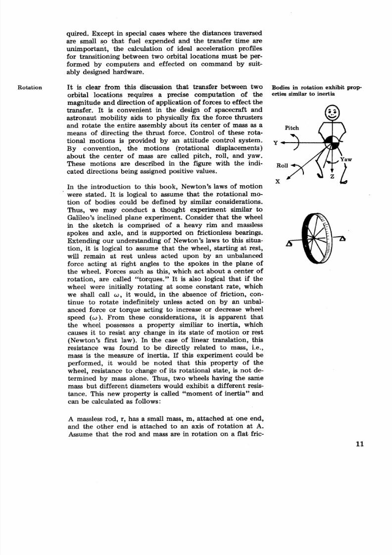
I t is clear from this discussion that transfer between two Bodies in rotation exhibit prop-
orbital locations requires a precise computation of the erties similar to inertia
magnitude and direction of application of forces to effect the
transfer. It is convenient in the design of spacecraft and
astronaut mobility aids to physically fix the force thrusters
and rotate the entire assembly about its center of mass as a
means of directing the thrust force. Control of these rota-
tional motions is provided by an attitude control system.
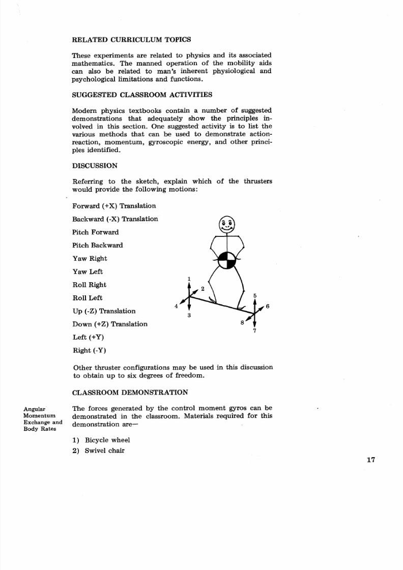
By convention, the motions (rotational displacements)
about the center of mass are called pitch, roll, and yaw.
These motions are described in the figure with the indi- Roll
cated directions being assigned positive values.
XIn the introduction to this book, Newton's laws of motion
' were stated. It is logical to assume that the rotational mo-
tion of bodies could be defined by similar considerations.
Thus, we may conduct a thought experiment similar to
Galileo's inclined plane experiment. Consider that the wheel
in the sketch is comprised of a heavy rim and massless
spokes and axle, and is supported on frictionless bearings.
Extending our understanding of Newton's laws to this situa-
tion, it is logical to assume that the wheel, starting at rest,
will remain at rest unless acted upon by an unbalanced
force acting at right angles to the spokes in the plane of
the wheel. Forces such as this, which act about a center of
rotation, are called "torques." It is also logical that if the
wheel were initially rotating at some constant rate, which
we shall call w, it would, in the absence of friction, con-
tinue to rotate indefinitely unless acted on by an unbal-
anced force or torque acting to increase or decrease wheel
speed (w). From these considerations, it is apparent that
the wheel possesses a property similiar to inertia, which
causes it to resist any change in its state of motion or rest
(Newton's first law). In the case of linear translation, this
resistance was found to be directly related to mass, i.e.,
mass is the measure of inertia. If this experiment could be
performed, it would be noted that this property of the
wheel, resistance to change of its rotational state, is not de-
termined by mass alone. Thus, two wheels having the sanie
mass but different diameters would exhibit a different resis-
tance. This new property is called "moment of inertia" and
can be calculated as follows:
A massless rod, r, has a small mass, m, attached at one end,
and the other end is attached to an axis of rotation at A.
Assume that the rod and mass are in rotation on a flat fric-
8/8/2019 Skylab Experiments. Volume 6 Mechanics
http://slidepdf.com/reader/full/skylab-experiments-volume-6-mechanics 22/40
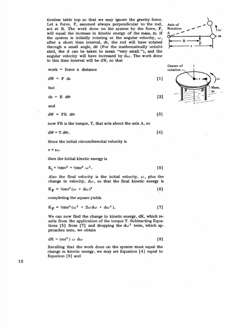
tionless table top so that we may ignore the gravity force.
Let a force, F, assumed always perpendicular to'the rod, Axis of
act at R. The work done on the system by the force, F, Rotation /
b
will equal the increase in kinetic energy of the mass, m. If A,-/ \ t
the system is initially rotating at the angular velocity, w,
after a short time interval, dt, the rod will have rotated
through a small angle, dB (For the mathematically uniniti-
ated, the d can be taken to mean "very small."), and the
angular velocity will have increased by d o . The work done
in this time interval will be dW, so that
Center of Iwork = force x distance
dW = F ds [I]
but-m
ds = R dO 121
-- ,/nd
now FR is the torque, T, that acts about the axis A, so
dw = T ~ O . [41
Since the initial circumferential velocity is
then the initial kinetic energy is
Also the final velocity is the initial velocity, w, plus the
change in velocity, dw, so that the final kinetic energy is
completing the square yields
We can now find the change in kinetic energy, dK, which re-sults from the application of the torque T. Subtracting Equa-
tions [5] from [7] and dropping the dwZ term, which ap-
proaches zero, we obtain
Recalling that the work done on the system must equal the
change in kinetic energy, we may set Equation [4] equal to
Equation [8] and
8/8/2019 Skylab Experiments. Volume 6 Mechanics
http://slidepdf.com/reader/full/skylab-experiments-volume-6-mechanics 23/40
Dividing both sides by d t (time), we have
bu t d@ /d t s the angular velocity of the wheel, w ,and d o d t
is th e angular acceleration of th e wheel, a , hence
The similarity between Equation [9 ] and Newton's equation
f = ma for linear motion of a mass acted on by an unbalanced
force is apparent. So that torque is the rotational analog of
force; a is the rotational analog of acceleration; and mr2 is
the rotational analog of mass (inertia). In rotational systems,
mr2 is called moment of inertia and is designated by the
letter I.
So that
The calculation of moment of inertia for other than very sim-
ple bodies must be performed by the methods of calculus and
the reader is referred t o t he numerous literature available on
this subject.
The Skylab program incorporates several unique pieces of
hardware which will be evaluated by the crew for future
orbital operations. These experiments are discussed in the
following paragraphs.
EXPERIMENT OBJECTIVES
The objectives of these experiments are to evaluate the de-
sign of maneuvering devices in a weightless environment
and to demonstrate the capabilities of the devices. The data
and experience gained during the performance of these ex-
periments will be related to ground-based analysis and simu-
lation.
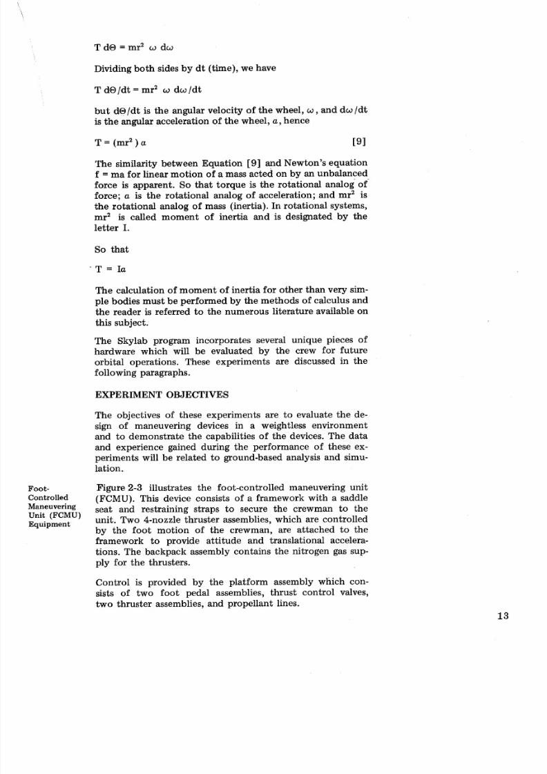
~ o o t - Figure 2-3 illustrates the foot-controlled maneuvering unitControlled (FCMU). This device consists of a framework with a saddle
Maneuvering seat and restraining straps to secure the crewman to the
UnitquipmentFCMU) unit. Two 4-nozzle thruster assemblies, which are controlledby the foo t motion of the crewman, are attached to the
framework to provide attitude and translational accelera-
tions. The backpack assembly contains the nitrogen gas sup-
ply for the thrusters.
Control is provided by the platform assembly which con-
sists of two foot pedal assemblies, thrust control valves,
two thruster assemblies, and propellant lines.
8/8/2019 Skylab Experiments. Volume 6 Mechanics
http://slidepdf.com/reader/full/skylab-experiments-volume-6-mechanics 24/40
8/8/2019 Skylab Experiments. Volume 6 Mechanics
http://slidepdf.com/reader/full/skylab-experiments-volume-6-mechanics 25/40
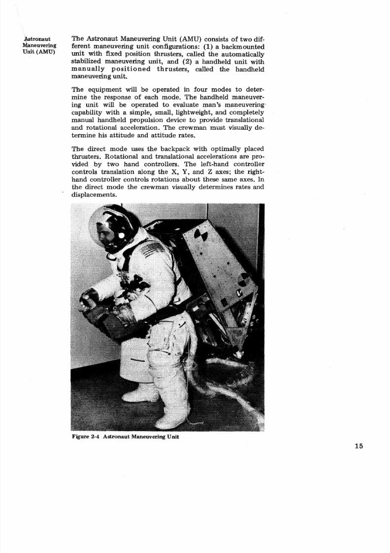
&tronaut The Astronaut Maneuvering Unit (AMU) consists of two dif-Maneuvering ferent maneuvering unit configurations: (1) backmountedUnit(AMU) unit with fixed position thrusters, called the automatically
stabilized maneuvering unit, and (2) a handheld unit with
manually positioned thrusters, called the handheld
maneuvering unit.
The equipment will be operated in four modes to deter-mine the response of each mode. The handheld maneuver-
ing unit will be operated to evaluate man's maneuvering,
capability with a simple, small, lightweight, and completely
manual handheld propulsion device to provide translational
and rotational acceleration. The crewman must visually de-
termine his attitude and attitude rates.
The direct mode uses the backpack with optimally placed
thrusters. Rotational and translational accelerations are pro-
vided by two hand controllers. The left-hand controller
controls translation along the X, Y, and Z axes; the right-
hand controller controls rotations about these same axes. In
the direct mode the crewman visually determines rates and
displacements.
Figure 2-4 Astronaut Maneuvering Unit
8/8/2019 Skylab Experiments. Volume 6 Mechanics
http://slidepdf.com/reader/full/skylab-experiments-volume-6-mechanics 26/40
Another mode will use the backpack with a rate-sensing at-
titude control system. A fourth mode will use a torque bal-
ance control moment gyro attitude control system. This
mode is similar to the rate-sensing attitude except that atti-
tude control is provided through momentum exchange in-
stead of through use of the thrusters.
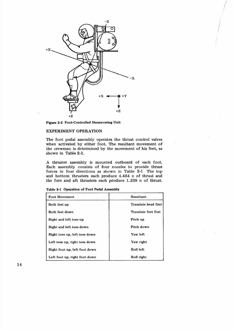
EXPERIMENT OPERATION
The operation of the handheld unit and the backpack in the
direct mode is similar in principle to the foot-controlled
maneuvering unit in that rotation and translation are con-
trolled manually by the operator.
The rate gyro mode employs the gas expulsion system also,
but in an automatic mode for the attitude control. Three rate
gyros detect rotational rates in roll, pitch, and yaw and, with. associated electronics, fire the appropriate thrusters t o main-
tain the astronaut in the correct attitude.
The fourth mode also uses gas expulsion for accelerating the
astronaut, but has a momentum exchange system to provide
attitude control. The momentum exchange system consists of
a series of control moment gyros and associated electronics.
EXPERIMENT DATA
The FCMU experiment uses two motion picture cameras, one
mounted in the workshop dome and one mounted within the
frame of the foot-controlled maneuvering unit, to provide the
principal data for that device. Additional data is supplied by
recorded voice commentary and logbook entries.
It is anticipated that at least one of the test subjects will
operate both the AMU and the FCMU for comparison pur-
poses. The AMU uses one motion picture camera mounted in
the workshop dome and another mounted on the workshop
wall. Analysis of camera data will permit determination of
the astronaut's position and velocity. This equipment is
instrumented to record numerous significant engineering data
points including pertinent information on the handheld
maneuvering unit and biomedical data during the pressure-
suited runs. This data is sensed, collected, and telemetered
from the maneuvering device to a receiver within the work-
shop and, together with recorded voice commentary, is later
sent to ground stations. Crew performance while flying com-
puter modeled systems on the ground will also be available.
8/8/2019 Skylab Experiments. Volume 6 Mechanics
http://slidepdf.com/reader/full/skylab-experiments-volume-6-mechanics 27/40
8/8/2019 Skylab Experiments. Volume 6 Mechanics
http://slidepdf.com/reader/full/skylab-experiments-volume-6-mechanics 28/40
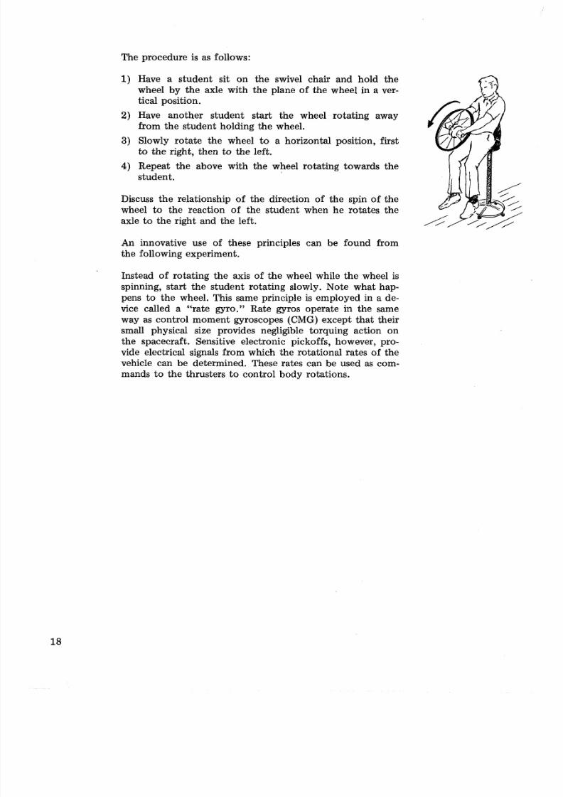
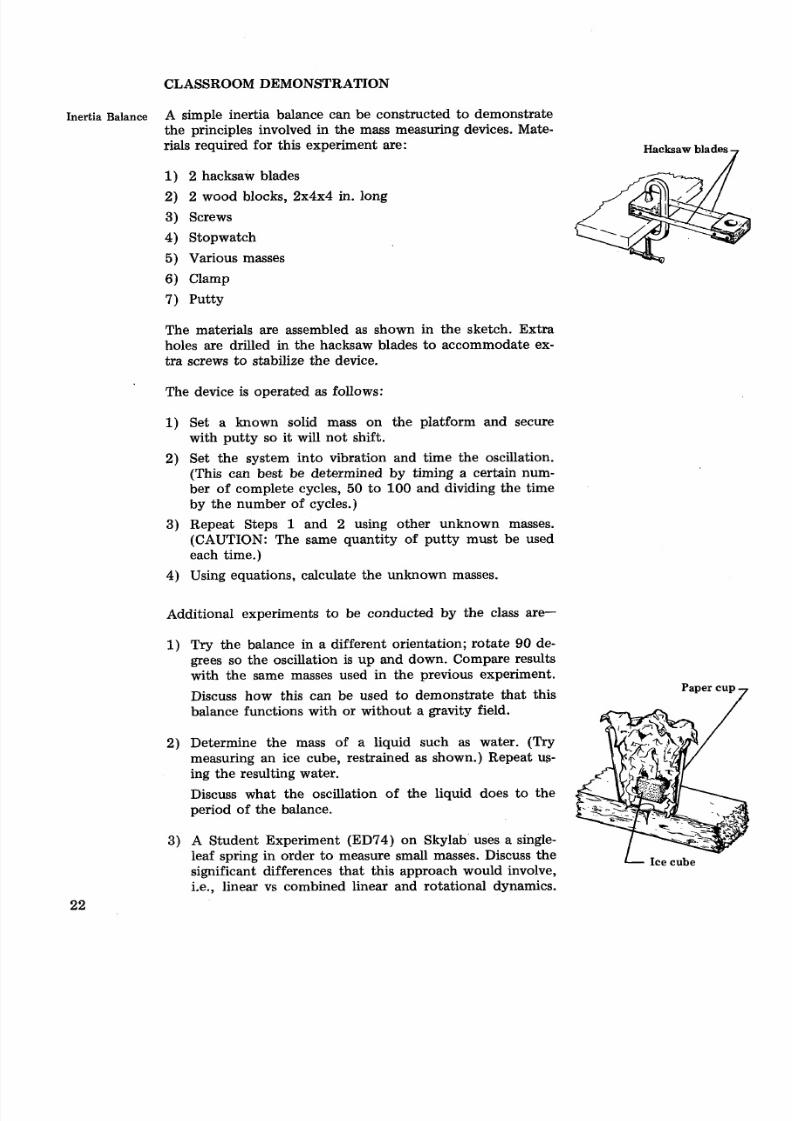
The procedure is as follows:
1) Have a student sit on the swivel chair and hold the
wheel by the axle with the plane of the wheel in a ver-
tical position.
2) Have another student start the wheel rotating away
from the student holding the wheel.
3) Slowly rotate the wheel to a horizontal position, firstto the right, then to the left.
4) Repeat the above with the wheel rotating towards thestudent.
Discuss the relationship of the direction of the spin of the
wheel to the reaction of the student when he rotates the
axle to the right and the left.
An innovative use of these principles can be found from
the following experiment.
Instead of rotating the axis of the wheel while the wheel is
spinning, start the student rotating slowly. Note what hap-
pens to the wheel. This same principle is employed in a de-
vice called a "rate gyro." Rate gyros operate in the same
way as control moment gyroscopes (CMG) except that their
small physical size provides negligible torquing action on
the spacecraft. Sensitive electronic pickoffs, however, pro-
vide electrical signals from which the rotational rates of the
vehicle can be determined. These rates can be used as com-
mands to the thrusters to control body rotations.
8/8/2019 Skylab Experiments. Volume 6 Mechanics
http://slidepdf.com/reader/full/skylab-experiments-volume-6-mechanics 29/40
Section 3
Mass Measurement Devices
8/8/2019 Skylab Experiments. Volume 6 Mechanics
http://slidepdf.com/reader/full/skylab-experiments-volume-6-mechanics 30/40
EXPERIMENT BACKGROUND
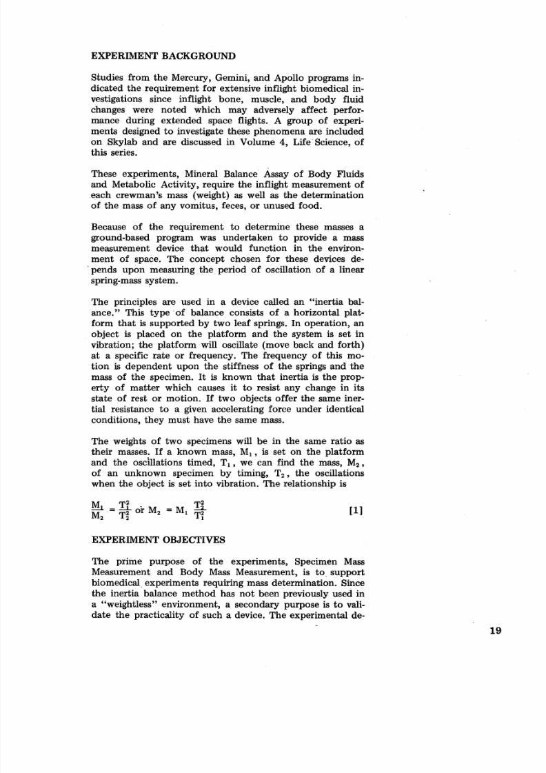
Studies from the Mercury, Gemini, and Apollo programs in-
dicated the requirement for extensive inflight biomedical in-
vestigations since inflight bone, muscle, and body fluid
changes were noted which may adversely affect perfor-
mance during extended space flights. A group of experi-
ments designed to investigate these phenomena are included
on Skylab and are discussed in Volume 4, Life Science, of
this series.
These experiments, Mineral Balance Assay of Body Fluids
and Metabolic Activity, require the inflight measurement of
each crewman's mass (weight) as well as the determination
of the mass of any vomitus, feces, or unused food.
Because of the requirement to determine these masses a
ground-based program was undertaken to provide a mass
measurement device that would function in the environ-
ment of space. The concept chosen for these devices de-
pends upon measuring the period of oscillation of a linear
spring-mass system.
The principles are used in a device called an "inertia bal-
ance." This type of balance consists of a horizontal plat-
form that is supported by two leaf springs. In operation, an
object is placed on the platform and the system is set in
vibration; the platform will oscillate (move back and forth)
at a specific rate or frequency. The frequency of this mo-
tion is dependent upon the stiffness of the springs and the
mass of the specimen. It is known that inertia is the prop-
erty of matter which causes it to resist any change in its
state of rest or motion. If two objects offer the same iner-
tial resistance to a given accelerating force under identical
conditions, they must have the same mass.
The weights of two specimens will be in the same ratio as
their masses. If a known mass, MI, is set on the platform
and the oscillations timed, T I , we can find the mass, M2,
of an unknown specimen by timing, T2 , the oscillations
when the object is set into vibration. The relationship is
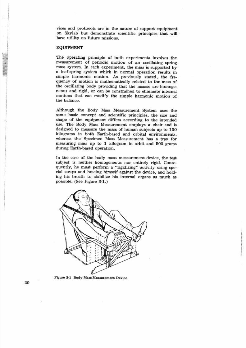
EXPERIMENT OBJECTIVES
The prime purpose of the experiments, Specimen Mass
Measurement and Body Mass Measurement, is to , support
biomedical, experiments requiring mass determination. Since
the inertia balance method has not been previously used in
a "weightless" environment, a secondary purpose is to vali-
date the practicality of such a device. The experimental de-
8/8/2019 Skylab Experiments. Volume 6 Mechanics
http://slidepdf.com/reader/full/skylab-experiments-volume-6-mechanics 31/40
8/8/2019 Skylab Experiments. Volume 6 Mechanics
http://slidepdf.com/reader/full/skylab-experiments-volume-6-mechanics 32/40
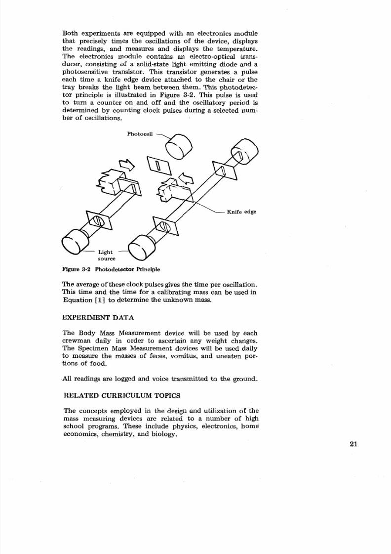
Both experiments are equipped with an electronics module
that precisely times the oscillations of the device, displays
the readings, and measures and displays the temperature.
The electronics module contains an electro-optical trans-
ducer, consisting of a solid-state light emitting diode and a
photosensitive transistor. This transistor generates a pulse
each time a knife edge device attached to the chair or the
tray breaks the light beam between them. This photodetec-
tor principle is illustrated in Figure 3-2. This pulse is used
to turn a counter on and off and the oscillatory period is
determined by counting clock pulses during a selected num-
ber of oscillations.
wp Light
source
Figure 3-2 Photodetector Principle
The average of these clock pulses gives the time per oscillation.
This time and the time for a calibrating mass can be used in
Equation [ I ] o determine the unknown mass.
EXPERIMENT DATA
The Body Mass Measurement device will be used by each
crewman daily in order to ascertain any weight changes.
The Specimen Mass Measurement devices will be used daily
to measure the masses of feces, vomitus, and uneaten por-
tions of food.
All readings are logged and voice transmitted to the ground.
RELATED CURRICULUM TOPICS
The concepts employed in the design and utilization of the
mass measuring devices are related to a number of high
school programs. These include physics, electronics, home
economics, chemistry, and biology.
8/8/2019 Skylab Experiments. Volume 6 Mechanics
http://slidepdf.com/reader/full/skylab-experiments-volume-6-mechanics 33/40
8/8/2019 Skylab Experiments. Volume 6 Mechanics
http://slidepdf.com/reader/full/skylab-experiments-volume-6-mechanics 34/40
Section 4Space Guidance
CrewAIehicle Disturbances
8/8/2019 Skylab Experiments. Volume 6 Mechanics
http://slidepdf.com/reader/full/skylab-experiments-volume-6-mechanics 35/40
EXPERIMENT BACKGROUND
There is an obvious need for an attitude control system on Translation between locations
an orbiting spacecraft. Some of the most stringent require- requires control of attitude so
ments imposed upon a spacecraft in regard to attitude con-that forces are directed
trol arise from the operation of photographic experiments
that require long exposure times. Some of these require-
ments are discussed in Volumes 1, 2, and 5 of this series.
In order to establish an optimum design for such a system,
it is necessary to know more precisely how the vehicle is
affected by the forces acting upon it; In this regard it
should be noted that forces acting on the vehicle (crew mo-
tions) internal to the vehicle can only produce net rota-
tional disturbances; external forces can produce both net
translational and rotational disturbances. For this reason, an
experiment related t o crew vehicle disturbances is included
and the reaction of the experiment pointing control system
of the Skylab will be monitored to ascertain the effect of
various crew disturbances.
EXPERIMENT OBJECTIVES
The objectives of this experiment are to obtain a series of
measurements under controlled conditions to evaluate
spacecraft disturbances caused by typical inflight crew mo-
tions and to verify the data from a ground-based simulation
program.
EQUIPMENT
The equipment for this experiment consists of a Force
Measuring System, a Limb Motion Sensor Assembly and as-sociated electronics for collecting and storing the data.
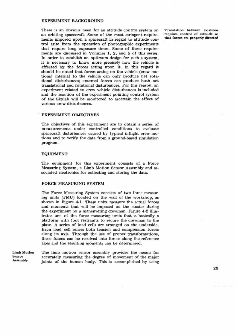
FORCE MEASURING SYSTEM
The Force Measuring System consists of two force measur-
ing units (FMU) located on the wall of the workshop, as
shown in Figure 4-1. These units measure the actual forces
and moments that will be imposed on the cluster during
the experiment by a maneuvering crewman. Figure 4-2 illus-
trates one of the force measuring units that is basically a
platform with foot restraints to secure the crewman to the
plate. A series of load cells are arranged on the underside.
Each load cell senses both tension and compression forces
along its axis. Through the use of proper transformations,
these forces can be resolved into forces along the reference
axes and the resulting moments can be determined.
Limb Motion The limb motion sensor assembly provides the means forSensor accurately measuring the degree of movement of the majorAssembly joints of the human body. This is accomplished by using
8/8/2019 Skylab Experiments. Volume 6 Mechanics
http://slidepdf.com/reader/full/skylab-experiments-volume-6-mechanics 36/40
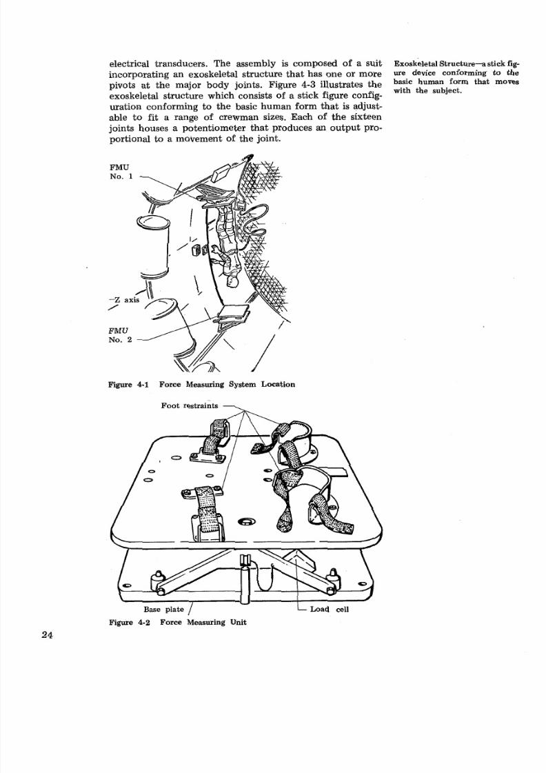
electrical transducers. The assembly is composed of a suit Exoskeletal Structure- stick f
incorporating an exoskeletal structure that has one or more ure device conforming to t
pivots at the major body joints. Figure 4-3 illustrates the basic human form thatwith the subject.
exoskeletal structure which consists of a stick figure config-
uration conforming to the basic human form tha t is adjust-
able to fit a range of crewman sizes. Each of the sixteen
joints houses a potentiometer that produces an output pro-portional to a movement of the joint.
Figure 4-1 Force Measuring System Location
Foot restraints --\
Base plate / Load cell
Figure 4-2 Force Measuring Unit
8/8/2019 Skylab Experiments. Volume 6 Mechanics
http://slidepdf.com/reader/full/skylab-experiments-volume-6-mechanics 37/40
AdjustmentAdjustment
mechanismmechanism 7.8 in.
320 deg
L10
1% in.
are potentiometer
transducers
Figure 4-3 Exoskeletal Structure
EXPERIMENT OPERATION
A crewman wearing the limb motion sensor assembly will
secure his .feet to the force measuring system and perform
various movements. In addition to various limb and bodymovements and translations between FMUs, the crewman
will simulate such actions as coughing and sneezing. Other
experiment sequences require the astronaut to maneuver be-
tween FMUs and to stop his motions with his hands.
EXPERIMENT DATA
While a crewman is performing the maneuvers, motion pic-
tures will be taken to provide a photographic time history
of the experiment. Subsequent evaluation of the photo-
graphic data will permit determination of the position of
the astronaut's center of mass relative to the spacecraft'scenter of mass. In addition, the outputs of the load cells,
the potentiometers, and the reaction of the cluster attitude
control system will be recorded along with voice reactions
of the crewmen.
RELATED CURRICULUM TOPICS
This experiment can be related to high school curriculum in
such areas as physics and its associated mathematics. These
8/8/2019 Skylab Experiments. Volume 6 Mechanics
http://slidepdf.com/reader/full/skylab-experiments-volume-6-mechanics 38/40
Dynamic data can be used to enhance design of anthropometricVehicle mechanisms, and, in a limited way, may supplement ana-
Disturbances tomical studies.
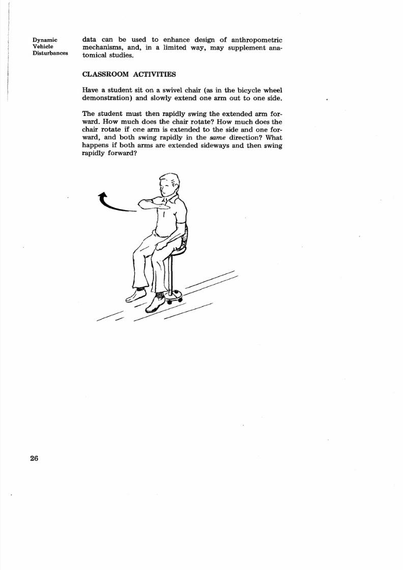
CLASSROOM ACTIVITIES
Have a student sit on a swivel chair (as in the bicycle wheel
demonstration) and slowly extend one arm out to one side.
The student must then rapidly swing the extended arm for-
ward. How much does the chair rotate? How much does the
chair rotate if one arm is extended to the side and one for-
ward, and both swing rapidly in the same direction? What
happens if both arms are extended sideways and then swing
rapidly forward?
8/8/2019 Skylab Experiments. Volume 6 Mechanics
http://slidepdf.com/reader/full/skylab-experiments-volume-6-mechanics 39/40
Section 5
Selected Bibliography
8/8/2019 Skylab Experiments. Volume 6 Mechanics
http://slidepdf.com/reader/full/skylab-experiments-volume-6-mechanics 40/40