Embed Size (px)
Citation preview
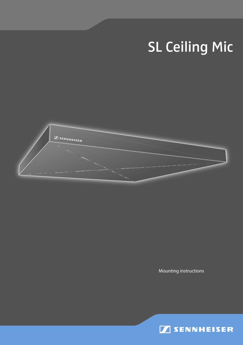
SL Ceiling Mic
Mounting instructions
SL Ceiling Mic | 1
Contents
You will find a PDF version of this instruction manual in the download area of the TeamConnect Ceiling product page at www.sennheiser.com.
ContentsImportant safety instructions . . . . . . . . . . . . . . . . . . . . . . . . . . . . . . . . . . . . . . . . . . . . . . . . . . . . . . . . . . . . . 2
Safety instructions for installation . . . . . . . . . . . . . . . . . . . . . . . . . . . . . . . . . . . . . . . . . . . . . . . . . . . . . . . 3
Package contents . . . . . . . . . . . . . . . . . . . . . . . . . . . . . . . . . . . . . . . . . . . . . . . . . . . . . . . . . . . . . . . . . . . . . . . . 4
Product overview . . . . . . . . . . . . . . . . . . . . . . . . . . . . . . . . . . . . . . . . . . . . . . . . . . . . . . . . . . . . . . . . . . . . . . . . 5Bottom side . . . . . . . . . . . . . . . . . . . . . . . . . . . . . . . . . . . . . . . . . . . . . . . . . . . . . . . . . . . . . . . . . . . . . . . . . . . 5
Top side . . . . . . . . . . . . . . . . . . . . . . . . . . . . . . . . . . . . . . . . . . . . . . . . . . . . . . . . . . . . . . . . . . . . . . . . . . . . . . . 5
Installing the SL Ceiling Mic . . . . . . . . . . . . . . . . . . . . . . . . . . . . . . . . . . . . . . . . . . . . . . . . . . . . . . . . . . . . . . . 7Installing the SL Ceiling Mic with the supplied ceiling suspension kit . . . . . . . . . . . . . . . . . . . . . . . . . 7
Installing the SL Ceiling Mic into an acoustic ceiling/panel ceiling . . . . . . . . . . . . . . . . . . . . . . . . . . . 10
Installing the SL Ceiling Mic with the optional ceiling fixation bracket . . . . . . . . . . . . . . . . . . . . . . . 11
Connecting the cables . . . . . . . . . . . . . . . . . . . . . . . . . . . . . . . . . . . . . . . . . . . . . . . . . . . . . . . . . . . . . . . . . . .13
Connecting the SL Ceiling Mic to the TeamConnect system . . . . . . . . . . . . . . . . . . . . . . . . . . . . . . . . . . .14
Configuring the SL Ceiling Mic via software . . . . . . . . . . . . . . . . . . . . . . . . . . . . . . . . . . . . . . . . . . . . . . . .15
Specifications . . . . . . . . . . . . . . . . . . . . . . . . . . . . . . . . . . . . . . . . . . . . . . . . . . . . . . . . . . . . . . . . . . . . . . . . . .16SL Ceiling Mic . . . . . . . . . . . . . . . . . . . . . . . . . . . . . . . . . . . . . . . . . . . . . . . . . . . . . . . . . . . . . . . . . . . . . . . . . 16
Power supply unit . . . . . . . . . . . . . . . . . . . . . . . . . . . . . . . . . . . . . . . . . . . . . . . . . . . . . . . . . . . . . . . . . . . . . 16
Manufacturer declarations . . . . . . . . . . . . . . . . . . . . . . . . . . . . . . . . . . . . . . . . . . . . . . . . . . . . . . . . . . . . . . .17
ENFR
ITPT
NL
PLSE
DK
FIGR
ESDE
2 | SL Ceiling Mic
Important safety instructions
Important safety instructions1. Read these instructions.
2. Keep these instructions. Always include these instructions when passing the apparatus on to third parties.
3. Heed all warnings.
4. Follow all instructions.
5. Do not use this apparatus near water.
6. Clean only with a dry cloth.
7. Do not block any ventilation openings. Install in accordance with the manufacturer‘s instructions.
8. Do not install near any heat sources such as radiators, heat registers, stoves, or other apparatus (including ampli-fiers) that produce heat.
9. Protect the power cord from being walked on or pinched, particularly at plugs, convenience receptacles, and the point where they exit from the apparatus.
10. Only use attachments/accessories specified by the manufacturer.
11. Use only with the cart, stand, tripod, bracket, or table specified by the manufacturer, or sold with the apparatus. When a cart is used, use caution when moving the cart/apparatus combination to avoid injury from tip-over.
12. Unplug this apparatus during lightning storms or when unused for long periods of time.
13. Refer all servicing to qualified service personnel. Servicing is required when the apparatus has been damaged in any way, such as power-supply cord or plug is damaged, liquid has been spilled or objects have fallen into the apparatus, the apparatus has been exposed to rain or moisture, does not operate normally, or has been dropped.
14. Use the mains plug to disconnect the apparatus from the mains.
15. Warning: To reduce the risk of fire or electric shock, do not expose this apparatus to rain or moisture.
16. Do not expose this equipment to dripping or splashing and ensure that no objects filled with liquids, such as vases, are placed on the equipment.
17. The mains plug of the power supply cord shall remain readily operable.
18. Ensure that the power supply is • properly plugged into the wall socket, • only operated within the permissible temperature range (see specifications), • not covered or exposed to direct sunlight for longer periods of time in order to prevent heat accumulation.
19. The power supply must be readily accessible so that the equipment can be easily disconnected from the AC power.
20. Do not attempt to service the power supply yourself, as opening or removing covers may expose you to dangerous voltage, and will void the limited warranty.
Risk of fire due to overloading
Do not overload wall outlets and extension cables as this may result in fire and electric shock.
Intended use
The product is designed for indoor use in meeting rooms, conference rooms and auditoriums.
The product can be used for commercial purposes.
It is considered improper use when this product is used for any application not named in the corresponding instruction manual.
Sennheiser does not accept any liability for damage arising from abuse or misuse of the product and its attachments/accessories
SL Ceiling Mic | 3
Important safety instructions
Safety instructions for installation
During installation, observe the following safety instructions.
f Have the product mounted and the electrical installations performed by a specialist. f Due to his/her technical training, know-how and experience as well as knowledge of relevant provisions, regulations
and standards, the specialist must be able to assess assigned tasks, recognize potential hazards and ensure appropriate safety measures.
f Observe and follow the local, national and international regulations and standards.
ENFR
ITPT
NL
PLSE
DK
FIGR
ESDE
4 | SL Ceiling Mic
Package contents
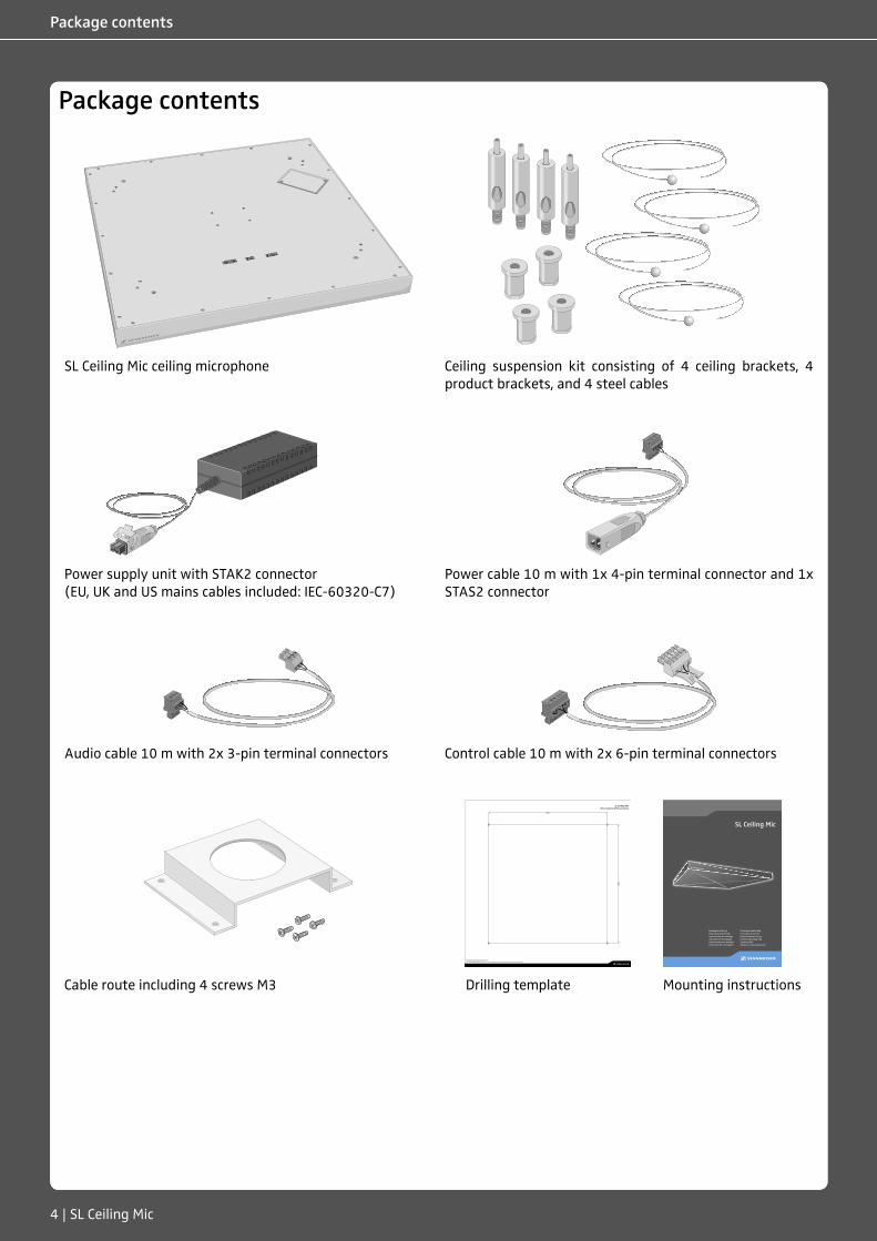
Package contents
SL Ceiling Mic ceiling microphone Ceiling suspension kit consisting of 4 ceiling brackets, 4 product brackets, and 4 steel cables
Power supply unit with STAK2 connector (EU, UK and US mains cables included: IEC-60320-C7)
Power cable 10 m with 1x 4-pin terminal connector and 1x STAS2 connector
Audio cable 10 m with 2x 3-pin terminal connectors Control cable 10 m with 2x 6-pin terminal connectors
420 mm16.53"
420 mm
16.53"
SL Ceiling MicBohrschablone/Drilling template
Sennheiser electronic GmbH & Co. KGAm Labor 1, 30900 Wedemark, Germany | www.sennheiser.com | Printed in Germany, Publ. 01/16, 566673/A01
SL Ceiling Mic
MontageanleitungMounting instructionsInstructions de montageIstruzioni di montaggioInstrucciones de montajeInstruções de montagem
MontagehandleidingInstrukcja montażuMonteringsanvisningMonteringsvejledningAsennusohjeΟδηγίες συναρµολόγησης
Cable route including 4 screws M3 Drilling template Mounting instructions
SL Ceiling Mic | 5
Product overview
Product overview
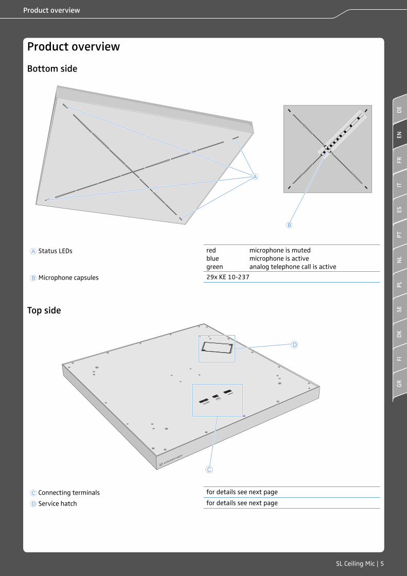
Bottom side
A
B
A Status LEDs red blue green
microphone is muted microphone is active analog telephone call is active
B Microphone capsules 29x KE 10-237
Top side
D
C
C Connecting terminals for details see next page
D Service hatch for details see next page
ENFR
ITPT
NL
PLSE
DK
FIGR
ESDE
6 | SL Ceiling Mic
Product overview
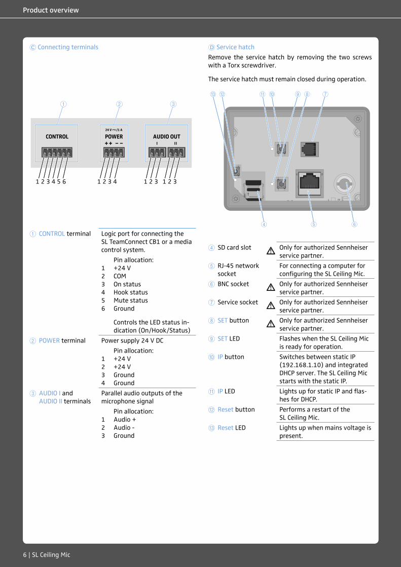
C Connecting terminals
1 2 3
1 2 3 1 2 31 2 3 4 1 2 3 4 5 6
1 CONTROL terminal Logic port for connecting the SL TeamConnect CB1 or a media control system.
1 2 3 4 5 6
Pin allocation: +24 V COM On status Hook status Mute status Ground
Controls the LED status in-dication (On/Hook/Status)
2 POWER terminal Power supply 24 V DC
1 2 3 4
Pin allocation: +24 V +24 V Ground Ground
3 AUDIO I and AUDIO II terminals
Parallel audio outputs of the microphone signal
1 2 3
Pin allocation: Audio + Audio - Ground
D Service hatch
Remove the service hatch by removing the two screws with a Torx screwdriver.
The service hatch must remain closed during operation.
4 5 6
0ABC 9 8 7
4 SD card slot Only for authorized Sennheiser service partner.
5 RJ-45 network socket
For connecting a computer for configuring the SL Ceiling Mic.
6 BNC socket Only for authorized Sennheiser service partner.
7 Service socket Only for authorized Sennheiser service partner.
8 SET button Only for authorized Sennheiser service partner.
9 SET LED Flashes when the SL Ceiling Mic is ready for operation.
0 IP button Switches between static IP (192.168.1.10) and integrated DHCP server. The SL Ceiling Mic starts with the static IP.
A IP LED Lights up for static IP and flas-hes for DHCP.
B Reset button Performs a restart of the SL Ceiling Mic.
C Reset LED Lights up when mains voltage is present.
SL Ceiling Mic | 7
Installing the SL Ceiling Mic
Installing the SL Ceiling Mic
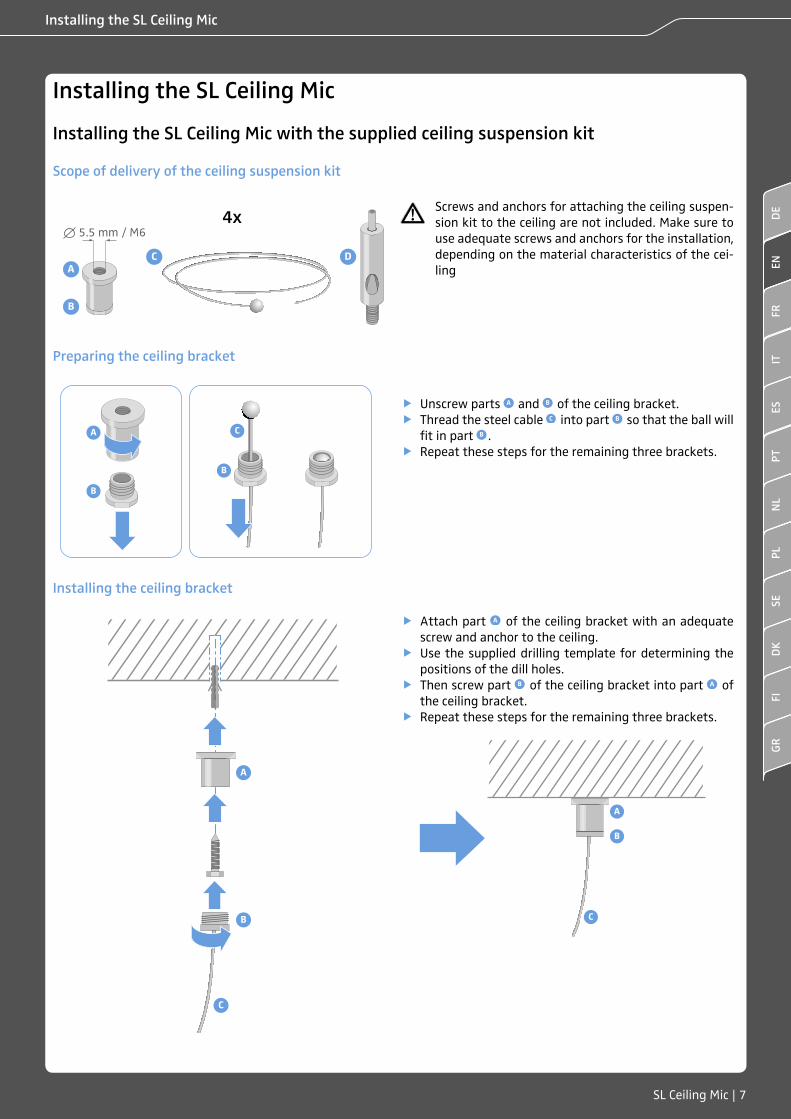
Installing the SL Ceiling Mic with the supplied ceiling suspension kit
Scope of delivery of the ceiling suspension kit
A
B
DC
4x5.5 mm / M6
Screws and anchors for attaching the ceiling suspen-sion kit to the ceiling are not included. Make sure to use adequate screws and anchors for the installation, depending on the material characteristics of the cei-ling
Preparing the ceiling bracket
A
B
B
C
1 f Unscrew parts A and B of the ceiling bracket. f Thread the steel cable C into part B so that the ball will
fit in part B . f Repeat these steps for the remaining three brackets.
Installing the ceiling bracket
A
B
C
f Attach part A of the ceiling bracket with an adequate screw and anchor to the ceiling.
f Use the supplied drilling template for determining the positions of the dill holes.
f Then screw part B of the ceiling bracket into part A of the ceiling bracket.
f Repeat these steps for the remaining three brackets.
A
B
C
ENFR
ITPT
NL
PLSE
DK
FIGR
ESDE
8 | SL Ceiling Mic
Installing the SL Ceiling Mic
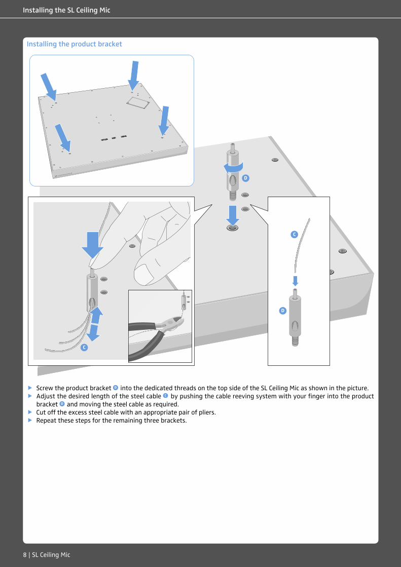
Installing the product bracket
D
C
D
C
f Screw the product bracket D into the dedicated threads on the top side of the SL Ceiling Mic as shown in the picture. f Adjust the desired length of the steel cable C by pushing the cable reeving system with your finger into the product
bracket D and moving the steel cable as required. f Cut off the excess steel cable with an appropriate pair of pliers. f Repeat these steps for the remaining three brackets.
SL Ceiling Mic | 9
Installing the SL Ceiling Mic
Adjusting the installation height
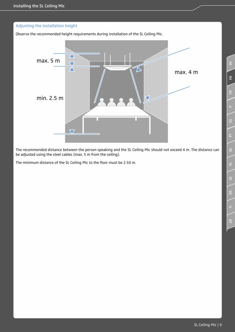
Observe the recommended height requirements during installation of the SL Ceiling Mic.
max. 5 m
min. 2.5 m
max. 4 m
The recommended distance between the person speaking and the SL Ceiling Mic should not exceed 4 m. The distance can be adjusted using the steel cables (max. 5 m from the ceiling).
The minimum distance of the SL Ceiling Mic to the floor must be 2.50 m.
ENFR
ITPT
NL
PLSE
DK
FIGR
ESDE
10 | SL Ceiling Mic
Installing the SL Ceiling Mic
Installing the SL Ceiling Mic into an acoustic ceiling/panel ceiling
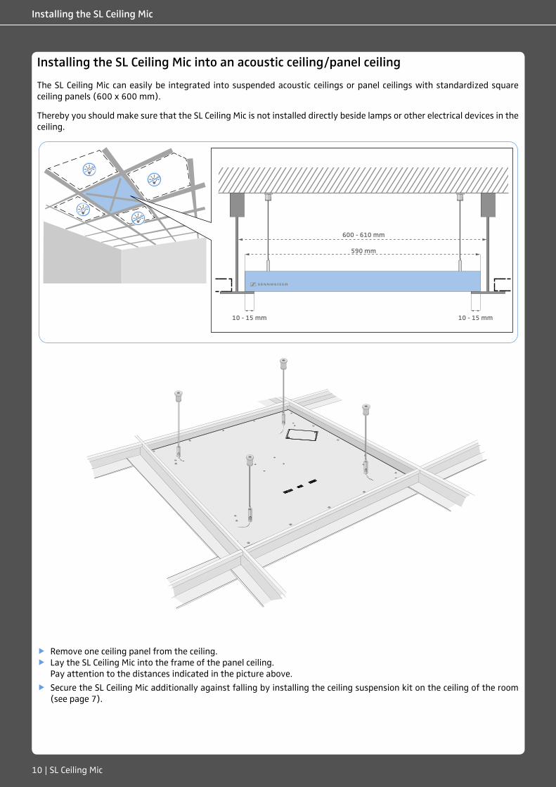
The SL Ceiling Mic can easily be integrated into suspended acoustic ceilings or panel ceilings with standardized square ceiling panels (600 x 600 mm).
Thereby you should make sure that the SL Ceiling Mic is not installed directly beside lamps or other electrical devices in the ceiling.
600 - 610 mm
590 mm
10 - 15 mm 10 - 15 mm
f Remove one ceiling panel from the ceiling. f Lay the SL Ceiling Mic into the frame of the panel ceiling.
Pay attention to the distances indicated in the picture above.
f Secure the SL Ceiling Mic additionally against falling by installing the ceiling suspension kit on the ceiling of the room (see page 7).
SL Ceiling Mic | 11
Installing the SL Ceiling Mic
Installing the SL Ceiling Mic with the optional ceiling fixation bracket
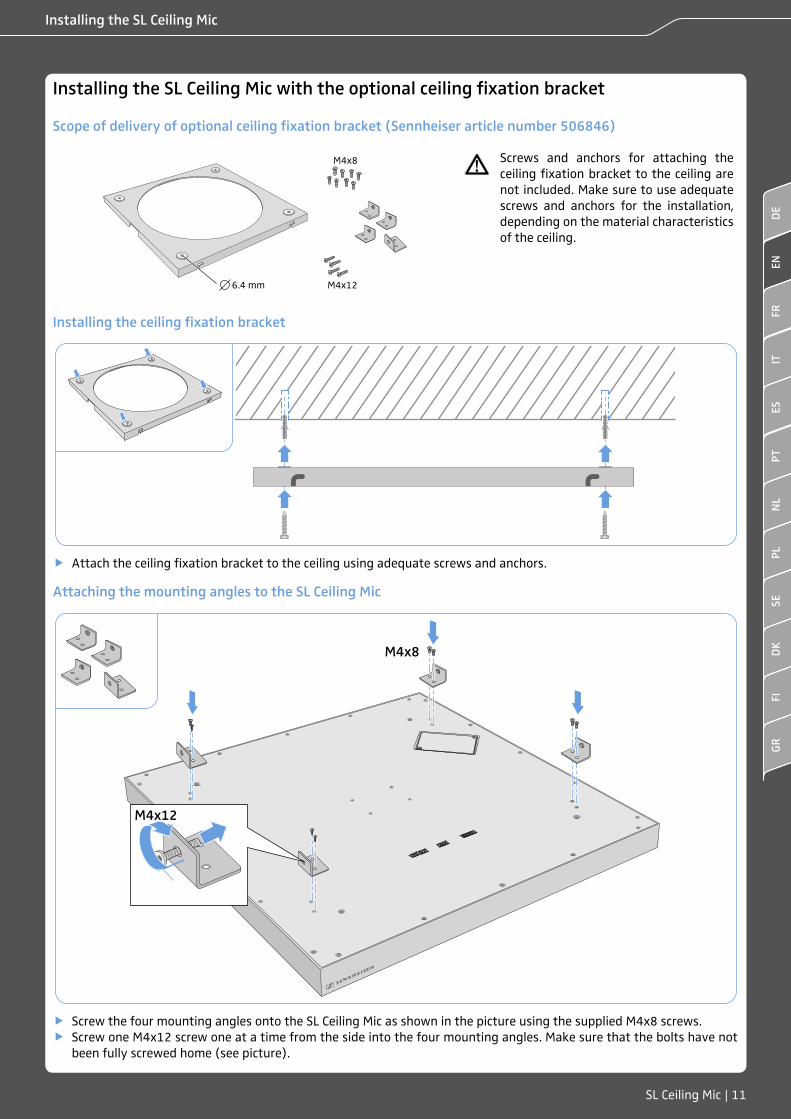
Scope of delivery of optional ceiling fixation bracket (Sennheiser article number 506846)
M4x126.4 mm
M4x8 Screws and anchors for attaching the ceiling fixation bracket to the ceiling are not included. Make sure to use adequate screws and anchors for the installation, depending on the material characteristics of the ceiling.
Installing the ceiling fixation bracket
f Attach the ceiling fixation bracket to the ceiling using adequate screws and anchors.
Attaching the mounting angles to the SL Ceiling Mic
M4x12
M4x8
f Screw the four mounting angles onto the SL Ceiling Mic as shown in the picture using the supplied M4x8 screws. f Screw one M4x12 screw one at a time from the side into the four mounting angles. Make sure that the bolts have not
been fully screwed home (see picture).
ENFR
ITPT
NL
PLSE
DK
FIGR
ESDE
12 | SL Ceiling Mic
Installing the SL Ceiling Mic
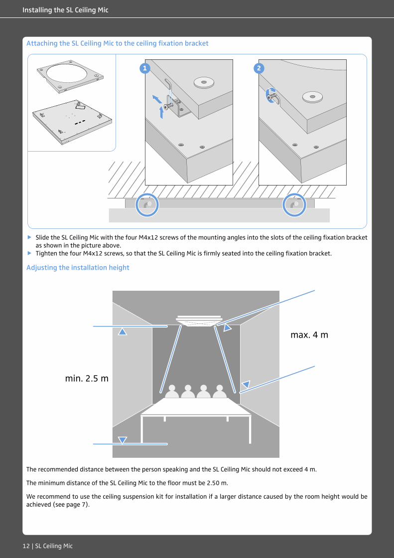
Attaching the SL Ceiling Mic to the ceiling fixation bracket
1 2
f Slide the SL Ceiling Mic with the four M4x12 screws of the mounting angles into the slots of the ceiling fixation bracket as shown in the picture above.
f Tighten the four M4x12 screws, so that the SL Ceiling Mic is firmly seated into the ceiling fixation bracket.
Adjusting the installation height
max. 4 m
min. 2.5 m
The recommended distance between the person speaking and the SL Ceiling Mic should not exceed 4 m.
The minimum distance of the SL Ceiling Mic to the floor must be 2.50 m.
We recommend to use the ceiling suspension kit for installation if a larger distance caused by the room height would be achieved (see page 7).
SL Ceiling Mic | 13
Connecting the cables
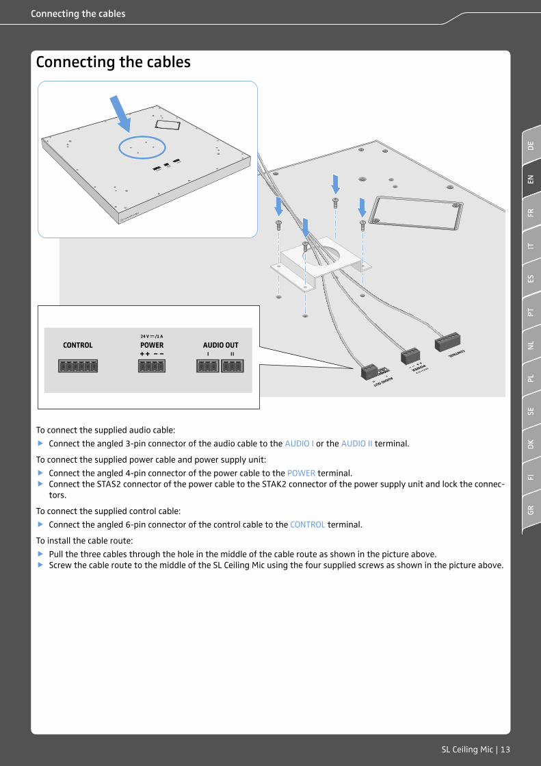
Connecting the cables
To connect the supplied audio cable:
f Connect the angled 3-pin connector of the audio cable to the AUDIO I or the AUDIO II terminal.
To connect the supplied power cable and power supply unit:
f Connect the angled 4-pin connector of the power cable to the POWER terminal. f Connect the STAS2 connector of the power cable to the STAK2 connector of the power supply unit and lock the connec-
tors.
To connect the supplied control cable:
f Connect the angled 6-pin connector of the control cable to the CONTROL terminal.
To install the cable route:
f Pull the three cables through the hole in the middle of the cable route as shown in the picture above. f Screw the cable route to the middle of the SL Ceiling Mic using the four supplied screws as shown in the picture above.
ENFR
ITPT
NL
PLSE
DK
FIGR
ESDE
14 | SL Ceiling Mic
Connecting the SL Ceiling Mic to the TeamConnect system
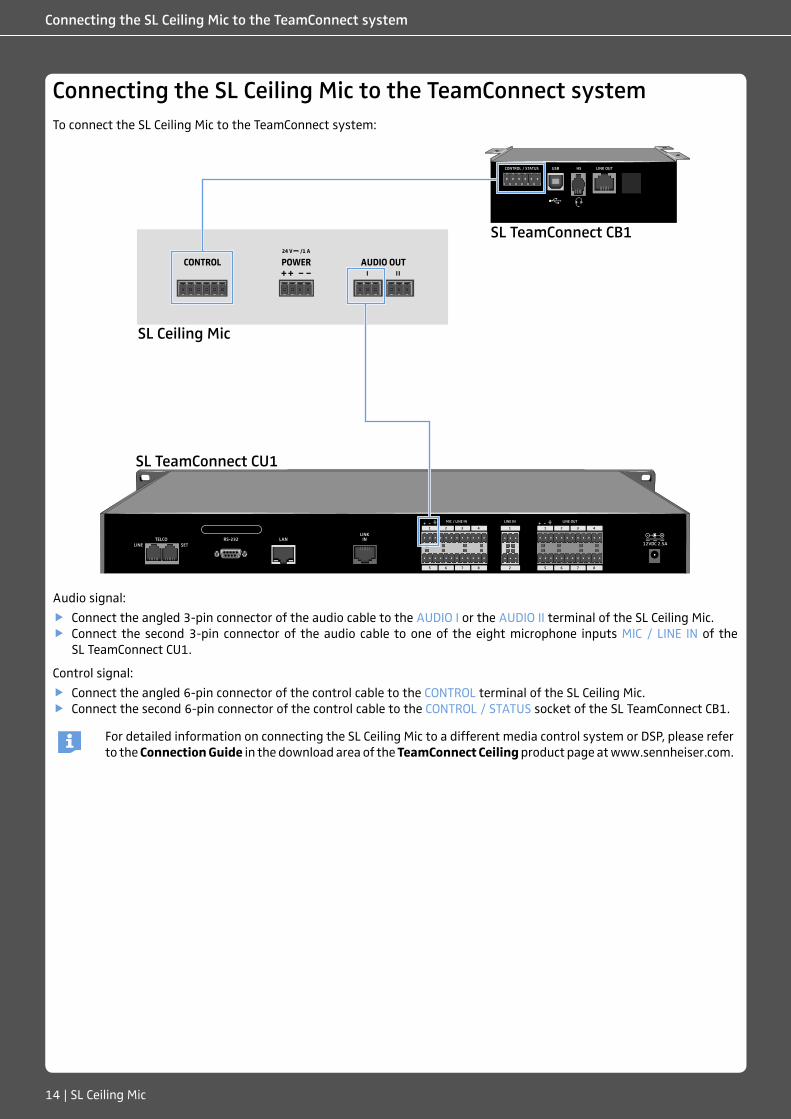
Connecting the SL Ceiling Mic to the TeamConnect systemTo connect the SL Ceiling Mic to the TeamConnect system:
SL TeamConnect CU1
SL TeamConnect CB1
SL Ceiling Mic
Audio signal:
f Connect the angled 3-pin connector of the audio cable to the AUDIO I or the AUDIO II terminal of the SL Ceiling Mic. f Connect the second 3-pin connector of the audio cable to one of the eight microphone inputs MIC / LINE IN of the
SL TeamConnect CU1.
Control signal:
f Connect the angled 6-pin connector of the control cable to the CONTROL terminal of the SL Ceiling Mic. f Connect the second 6-pin connector of the control cable to the CONTROL / STATUS socket of the SL TeamConnect CB1.
For detailed information on connecting the SL Ceiling Mic to a different media control system or DSP, please refer to the Connection Guide in the download area of the TeamConnect Ceiling product page at www.sennheiser.com.
SL Ceiling Mic | 15
Configuring the SL Ceiling Mic via software
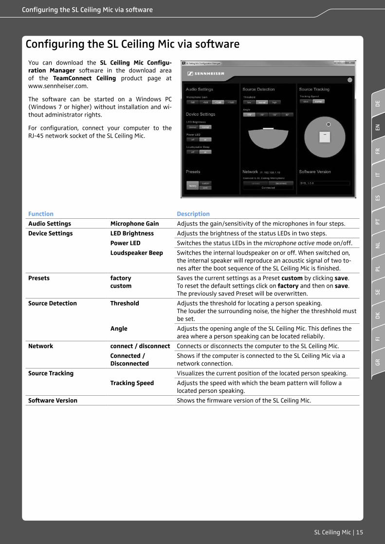
Configuring the SL Ceiling Mic via software
You can download the SL Ceiling Mic Configu-ration Manager software in the download area of the TeamConnect Ceiling product page at www.sennheiser.com.
The software can be started on a Windows PC (Windows 7 or higher) without installation and wi-thout administrator rights.
For configuration, connect your computer to the RJ-45 network socket of the SL Ceiling Mic.
Function Description
Audio Settings Microphone Gain Adjusts the gain/sensitivity of the microphones in four steps.
Device Settings LED Brightness Adjusts the brightness of the status LEDs in two steps.
Power LED Switches the status LEDs in the microphone active mode on/off.
Loudspeaker Beep Switches the internal loudspeaker on or off. When switched on, the internal speaker will reproduce an acoustic signal of two to-nes after the boot sequence of the SL Ceiling Mic is finished.
Presets factorycustom
Saves the current settings as a Preset custom by clicking save. To reset the default settings click on factory and then on save. The previously saved Preset will be overwritten.
Source Detection Threshold Adjusts the threshold for locating a person speaking.The louder the surrounding noise, the higher the threshhold must be set.
Angle Adjusts the opening angle of the SL Ceiling Mic. This defines the area where a person speaking can be located reliabily.
Network connect / disconnect Connects or disconnects the computer to the SL Ceiling Mic.
Connected / Disconnected
Shows if the computer is connected to the SL Ceiling Mic via a network connection.
Source Tracking Visualizes the current position of the located person speaking.
Tracking Speed Adjusts the speed with which the beam pattern will follow a located person speaking.
Software Version Shows the firmware version of the SL Ceiling Mic.
ENFR
ITPT
NL
PLSE
DK
FIGR
ESDE
16 | SL Ceiling Mic
Specifications
Specifications
SL Ceiling Mic
Dimensions (L x W x H) 590 x 590 x 43 mm (23.2" x 23.2" x 1.7")
Weight 6 kg (13.2 lbs)
AUDIO I and AUDIO II sockets 2 x 3-pin terminals (fits Phoenix Contact MCVW 1.5-3-ST-3.81)
POWER socket 4-pin terminal (fits Phoenix Contact MCVW 1.5-4-ST-3.81)
CONTROL socket 6-pin terminal (fits Phoenix Contact MCVW 1.5-6-ST-3.81)
Supply voltage 20 – 28 V DC
Power consumption 20 W
Environmental conditions
Temperature Operation: 0 – 40 °C (32 – 104 °F) Storage: -10 – 60 °C (14 – 140 °F)
Relative humidity 20 – 95 % non-condensing
Acoustics
Microphone type pre-polarized condenser microphone
Sensitivity -1 dBV/Pa (930 mV/Pa)
Equivalent noise level 20 dB(A)
Number of KE 10-237 microphone capsules
29
Pick-up pattern Beam pattern
Max. sound pressure level 119 dB SPL
Dynamic range 99 dB(A)
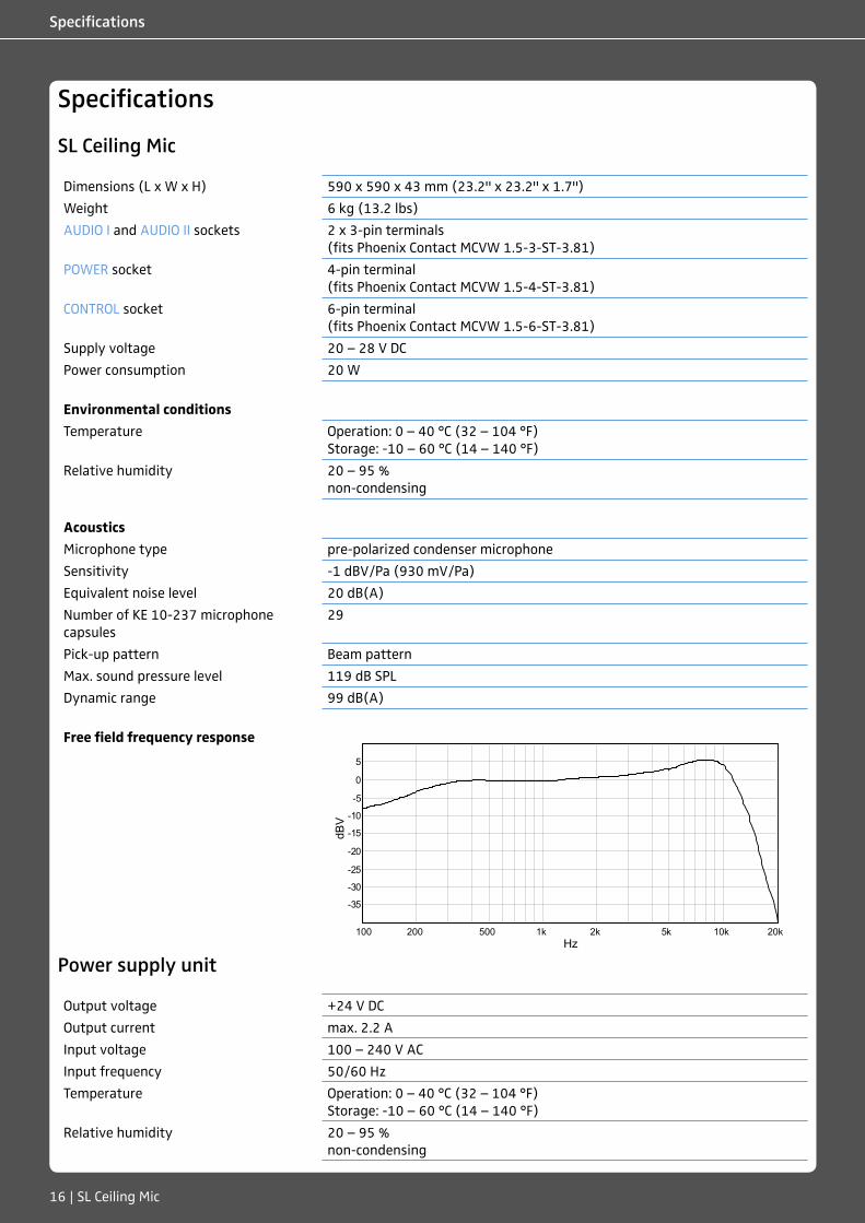
Free field frequency response
Power supply unit
Output voltage +24 V DC
Output current max. 2.2 A
Input voltage 100 – 240 V AC
Input frequency 50/60 Hz
Temperature Operation: 0 – 40 °C (32 – 104 °F) Storage: -10 – 60 °C (14 – 140 °F)
Relative humidity 20 – 95 % non-condensing
Hz100 1.000 10.000
dBV
5
0
-5
-10
-15
-20
-25
-30
-35
200100 500 1k 2k 5k 10k 20k
SL Ceiling Mic | 17
Manufacturer declarations
Manufacturer declarations
Warranty
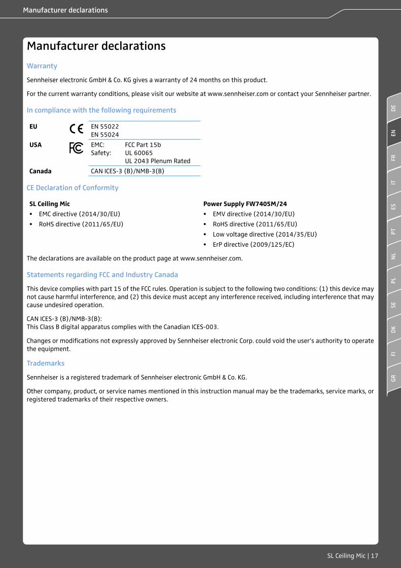
Sennheiser electronic GmbH & Co. KG gives a warranty of 24 months on this product.
For the current warranty conditions, please visit our website at www.sennheiser.com or contact your Sennheiser partner.
In compliance with the following requirements
EU EN 55022EN 55024
USA EMC: Safety:
FCC Part 15bUL 60065UL 2043 Plenum Rated
Canada CAN ICES-3 (B)/NMB-3(B)
CE Declaration of Conformity
SL Ceiling Mic Power Supply FW7405M/24
• EMC directive (2014/30/EU) • EMV directive (2014/30/EU)
• RoHS directive (2011/65/EU) • RoHS directive (2011/65/EU)
• Low voltage directive (2014/35/EU)
• ErP directive (2009/125/EC)
The declarations are available on the product page at www.sennheiser.com.
Statements regarding FCC and Industry Canada
This device complies with part 15 of the FCC rules. Operation is subject to the following two conditions: (1) this device may not cause harmful interference, and (2) this device must accept any interference received, including interference that may cause undesired operation.
CAN ICES-3 (B)/NMB-3(B): This Class B digital apparatus complies with the Canadian ICES-003.
Changes or modifications not expressly approved by Sennheiser electronic Corp. could void the user’s authority to operate the equipment.
Trademarks
Sennheiser is a registered trademark of Sennheiser electronic GmbH & Co. KG.
Other company, product, or service names mentioned in this instruction manual may be the trademarks, service marks, or registered trademarks of their respective owners.
ENFR
ITPT
NL
PLSE
DK
FIGR
ESDE

Sennheiser electronic GmbH & Co. KG
Am Labor 1, 30900 Wedemark, Germany www.sennheiser.comPubl. 04/16, 566672/A01