Embed Size (px)
Citation preview
Slab-jacking at Tarbela Dam,Pakistanby D. A. BRUCE', BSc, PhD, CEng, MICE, MIWES, FGS at G. M. JOYCE>, BSc(Mons), MIE(Aust)
This Paper describes a major slab-jackingprogramme conducted recently at TarbelaDam, Pakistan. Some 375ms of mainlycement~ ntorite grouts were injectedthrough 1 302 holes drilled through 39 ofthe concrete panels forming the protectiveapron to the upstream clay blanket mater-ial of the auxiliary spillway.
The purpose of the work was to restorefull contact between the panels and theblanket, and to lift the slabs to their origi-nal attitudes following localised erosion ofthe clay.
Data are provided on the design, controland effects of the slabjacking togetherwith fluid and set properties of the groutsemployed.
IntroductionTHE TARBELA DAM COMPLEX is one ofthe world's greatest water resource devel-opments and is located 70km north westof Islamabad, Pakistan (Fig. 1). The prin-cipal element of the project is the mainembankment dam, 2740m long, 143m highand comprising 130 million cubic metresof materials. Other major features are twopower and two 'irrigation tunnels on theright bank, the two smaller auxiliary dams(17.5 million cubic metres) and the twomassive concrete spillways (Fig. 2), sepa-rated by an additional irrigation tunnel onthe left bank.
The service spillway, with seven gatesdischarging water into the Indus Riverfrom July to September, has seen enor-mous rollcrete, concrete and rock anchorprotection works being carried out in itsplunge pool from 1977 to 1980 (e.g. Loweet. al., 1979). More recently, similar atten-tion has been focused on the auxiliary spill-way structure which is designed to operateonly for short periods of exceptionally highreservoir inflows, and when for any reasonthe service spillway is inoperable.
During the 1979-80 construction season,an important undertaking in this latter loca-tion was the contact grouting and liftingof certain concrete panels forming the up.stream protective apron (Fig. 3). Apartfrom its large scale —375m'f groutswere injected under an area of 6130m'—the slab-jacking operation was remarkablein that it was conducted with conventionalgrouting equipment and executed followingbasic engineering procedures and princip-les. This Paper details the development ofthese principles in the light of the suc-cessful conclusion of the work.
thinly bedded, and ferruginous and phylliticto the flanks. The limestones containsmall karstic features, with soft infill mat-erials. There are also some medium bedsof "sugary limestone" (calcarenite) whichare porous. The phyllites are schistose,occasionally talcosic and slightly metamor-phosed. To the right of the structure is amajor dolerite 'intrusion with occasionalserpentinised seams. All the lithologies areweathered, with some beds of soil-likecharacter.
These rocks constitute a relatively softand weak zone squeezed between a hugemass of quartzite to the left, and massivedolomite with igneous instrusions to theright. Within this zone there are shearfaults, overturned folds and tension cracks.The major discontinuities are bedding andfold joints (striking N45 - 65 E, dipping30-75'E), tension joints (striking N45-
Fig. 1. Tarbela Damcomp/ex, Pakistan
Intstru
Righbank
4Tunnels
Outlearea
55'W, open and spaced 4.5 - 9m) andshear faults (striking N30'E, cutting allother joints, and having gouge filled mater-ial). The high permeability (1 -3 x 10⁻⁴cm/sec) of the foundations is related toflow through the karstic network in thelimestone, evidently controlled by thejointing.
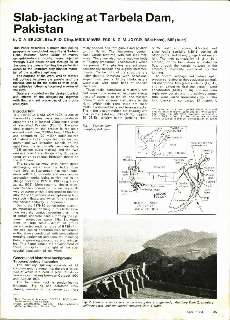
To control seepage and reduce upliftpressures related to these adverse geological conditions, two grout curtains (Fig. 4),and an extensive drainage system wereconstructed (Szalay, 1976). The upstreamtriple row curtain and the spillway struc-ture were linked horizontally by a 68mlong blanket of compacted B1 material",
saf material is a well graded blend of sounddurable angular gravel, sand and slit, with 20-40%finer than No. 200 sieve. Average permeability1.3 X 10-7 cm/sec, At the thickest section thedesign assumed maximum consolidation of 50mm
le~ TA R BE LA
ary1
iaryway
ngeool
nels
General and historical backgroundStructure/geology interaction
The auxiliary spillway consists of 22concrete gravity monoliths, the crest struc-ture of which is curved in plan. Construc-tion was carried out between October 1970and August 1974.
The foundation rock is predominantlylimestone (Fig. 4) and dolomitic lime-stones, massive in the centre but more
*Then Technical Manager, COLROK JV(colcreteRodio-Keller), Tarbela Dam
fHead Construction Engineer, Tibbetts-AbbettMccarthy-gtratton, Tarbela Dam.
.IFig. 2. General view of service spillway gates (foreground/, Auxiliary Dam 2, auxiliaryspillway gates, and the curved Auxiliary Dam 1, right
April, 1983 35
laid on the surface of the rock. The blanketties laterally into the cores of the AuxiliaryDams 1 and 2, and varies in thicknessfrom 9.5m in the trench immediately on theupstream side of the spillway headworksto 1 5m at its upstream edge. In thetrench, the rock had been treated by con-solidation grouting and the foundation rockof the 81 was subjected to dental concreteas required. The purpose of the 81 blanketis to lengthen the potential seepage pathso as to lower hydraulic gradients andthus uplift pressures under the spillway.The thickening of the blanket next to thespillway structure was to provide a signi-ficant seepage path at the soil/concreteinterface.
The blanket is capped with a 0.3-0.6mthick concrete apron (Fig. 3), constructedin panels, typically 15 x 11m, except atlocations permitting articulation so that theslab could follow any differential settle-ment of the blanket (Fig. 5). Waterstopsare installed at all joints between the pan-els. The purpose of the apron is to pre-vent erosion of the blanket due to spillwayoperation and to preclude the introductionof water at full reservoir pressure at thetop of the blanket at the soil/concrete in-terface at the spillway structure.Monitoring history
Continuous monitoring of the structure/rock system has been maintained from thefirst impounding in 1975. In 1978, all piezo-meters recorded significant increases dur-ing reservoir infill. Although these in-creases resulted in pressures which werewell within the design requirements for up-lift, there was concern that the increaseswere at least partly due to water bypass-ing the apron and blanket by seepingdown the upstream face of the headworks,and that the situation might deteriorate todangerous levels with time. While the re-servoir was still above apron level, saltconductivity tests were conducted whichdid indeed Indicate an important defectin the blanket integrity close to the head-works.
Investigations disclosed a triangularshaped void about 350mm deep next to thespillway structure. It was continuous andhad connection to the reservoir at the leftand right slab extremities. The presence ofslightly washed zones in the test pits fur-ther indicated some movement of fines atthe interface. Thus, the intent of the de-sign to preclude having water at full reser-voir pressure at the soil/concrete inter-face had been frustrated. Two phenomenawere thought to have led to this situation:
Max. lake El. 1550g Roadway
Gunite
0 50 100ftDrainage~curtain
Fig. 4. General cross-section of auxiliary spillway upstream protective works
tFig. 3. The concrete panels forming the protective apron on the upstream side of theauxiliary spillway headworks. Auxiliary Dam 1 to the left
rom
(i) Separation occurring along the con-tact due to the rotation of the head-works under high reservoir pressure,and
(ii) The connection between the apronand spillway structure not functioningas intended. As the fill settled underreservoir pressure the apron washanging up at the spillway structureallowing the formation of a void towhich reservoir water had accessfrom the sides. The water then en-tered the rotation crack washing 61material down the crack. This result-ed in the deeper triangular shaped de-pression at the concrete/soil inter-face.
Associated settlements of other panels,including differential movements, had alsobeen recorded, and by early 1980 theseranged from 30mm to 180mm, at distancesof 6m to 18m from the headworks. The
36 Ground Engineering
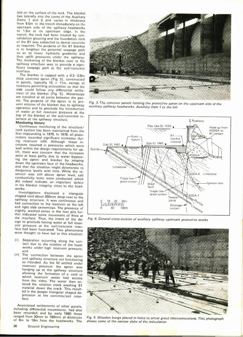
Fig. 5. Wooden bungs placedin holes to arrest groutinterconnections. This photographshows some of the narrow slabs of the articulation
72 21 20
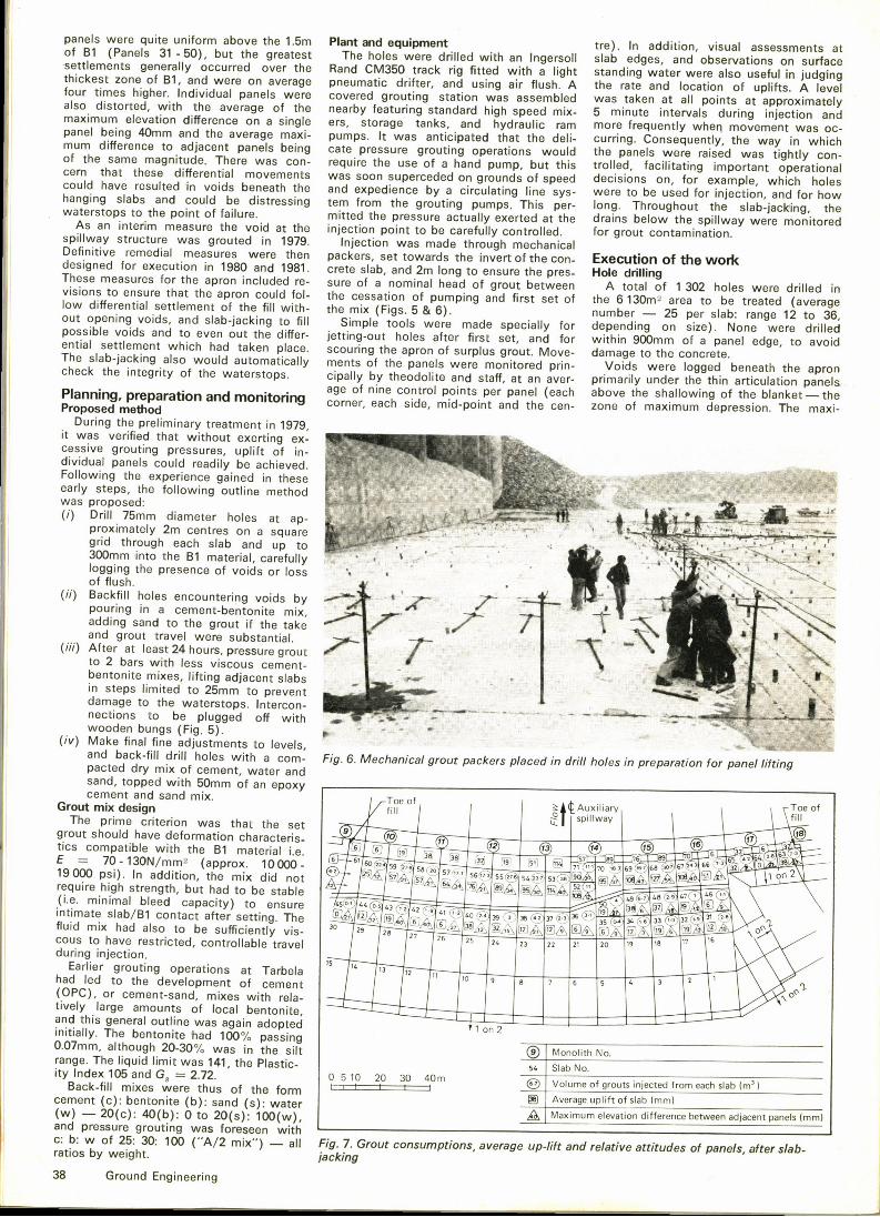
Q9 Monolith No.
Slab No.
Volume of grouts injected from each slab (m')Average uplift of slab (mm)
aximum'
between adjacent panels (mm)Maximum elevation difference e e
addition, visual assessments atplant and equlpmerttI,soll slab edges, and observe '
pane s were quite uniform aboveTh h Ies were drilled with an Ingerso d'er were also useful in judging
reatest e oesstan ing wa er
I
0f B1 (Panels 31-50), but the g
h A tll Mt
350 t c ng «ed th g
I
-sett erneI ments generally occurred o
e bid ti drifter, and using air flus .
k t all points at approximate y
'ual anels were covere
hi kest zone of B1, and were o
I cl
four times higher. Individu ps eed mix- 5 minu e i
was oc-
ra e of the near y g hgh pli ram more re
hich
max' 'ce on a single ers, s oramax' 'c ', t rage tanks, and hydrau 'c e wmaximum elevation differenc
It was anticipated that the deli- curring. onsh els were raised was tight yI con-
avera e maxi- pumps. 's would the pane srational
pa
t ressure grouting operation h e smum difference to adjac pent anels being ca e p
r was con- required
''f I hi
but this tro e,n superceded on grounds of sp eed decisions
wth the and expedience by a circulating
ntial movements was soon sin line sys- were to e u
ki, the
couf the grouting plumps Tuld be distressing tern rom
xerted at the drains e ow'tt d the pressure actually exe eh i etio oittob fll
of failure. mi entrolled. or grou
1979. I jectio d th
easure the void at the injec ion
rou h mechanicalE ecution of the workwere then packers set toward the
r was routed in
invert of the con- xres- Hole drilling
D f'nitive remedial measures were ene ini 'v
0 and 1981. crete s a, an
I f 1302 h I d ill df ominal head of grout betwween A tota o
e
esignron included re- sure o a no
i t set of the 6130me area36,
po
b r —25 per slab: range 12 to
ure that the apron could fol- t e cessvisions to ensureof the fill with- the mix (Figs. 5 8t 6).
iall for depending on size). None wII Sim le tools were made special y ooids, and slab-jacking to fi imp
er first set, and for wit in mmut the differ- jetting-out holes after irpos
the apron of surplus grout. Move- amments of the panels were monitored pr'-
h dolite and staff at an aver- prim
esa -j
I h b h
g y o
f ximum depression. The maxi-reParatlOn ants rnOn<tOnng corner, each side, mid-point an
Pianning, preProposed method
in 1979,During the preliminary treatment in
yl't
was verified that without exerting ex-u lift of in-cessive grouting pressures, up
'ividualpanels could readily be achieved.Following the experience gained in theseearly steps, t e o
ow'as
proposed:(i) Drill 75mm diameter holes at p-
proximately 2m centres on a qa s uare
mm'oggingthe presence of voids or oss 'e
of flush.
pouring inri in a cement-bentonite mix,take
t
adding sand to the grout if the ta e'.and grout travel were substantia.fter at least 24 hours, pressure grout
i
t" 6,
to 2 bars with less viscous cebentonite mixes, lifting adjacent slabsin steps limited to 25mm to preventdamage to the waterstops. Intercon-nections to be plugged off with
in drill holesin preparation for panel lifting
( ) fi
and back-fill drill holes with a corn- Fig.6. ec anicapacted dry mix of cement, water and
Toe of
sand, topped with 50mm of an epoxyToe of
g Auxiliaryf'll
cement and sand mix.fill
spillwayGrout mix design
The prime criterion was that the setgrout should have deformation characteristies compa i
~ 7 '7" '65»> 55~we 555775 55(75hi h strength, but had to be stablerequire ig s
ca acit ) to ensureVh
ui mixcous to have restricted, controllable trave I
I
during injection.Tarbela " " » „, a 7 5 5
Earlier grouting operations at Tarbe a
(OPC), or cement-sand, mixes with rela-
I
tively large amounts of local bentonite,
1 on2and this general outline was again adopteinitially. The bentonite had 100% passing0.07mm, although 20-30% was in the siltrange. The liquid limit was 141 the Plastic-ity Index 105 and Ga = 2.72.
Back-fill mixes were thus of the form( ): bentonite (b): sand (s): water
7 G o t o tio v rag up-lift and relative attitu es ok'5:
30: 100 ("A/2 mix") —all Fig.. rou cratios by weight.
38 Ground Engineering
mum void depth was 275mm (Panel 68)with other voids of up to 200mm noted to-wards the spillway. Elsewhere the generallimit was 50mm.Back-fill grouting
The original concept of gravity back-filling was pursued, but early results indi-cated nominal consumptions with no inter-connections. Indeed, only Panel 38 (Fig.7) accepted a volume of grout beyondthe initial cement-bentonite starting mix.By the same point, it was recognised thatthe initial pressure grouting with c:b.w—25: 30: 100 to 70 mixes was easily findingconnections with holes up to three slabsdistant. It was concluded that the firstobjective of vo'id infill and contact grout-ing could be effectively achieved by themethods originally intended for just the up-lift grouting. Gravity grouting was, there-fore, soon discontinued except for final'topping up'f holes at the conclusion ofthe pressure grouting.Pressure grouting
The pressure grouting commenced underPanel 44 (Fig. 7), and progressed from leftto right and in a general way towards theheadworks. The lifting of the lower slabswas initiated from one of the peripheralholes on one edge only, and continuedacross the slab. As the grout migrated.wooden plugs were driven into the holesfrom wh'ich grout emerged. Practice was topermit travel of up to 6m before furtherpackers were then installed nearer to thetravelling face of the grout and injectiontransferred to them. When approximatelytwo-thirds of the slab had been so treated,the grout line was returned to the firstpacker to attempt to lift that part of theslab.
An initial phase of lifting was conductedon a two shift per day basis, treating eachof the lowermost 32 slabs at least once.During this period, experience was gainedwhich proved of great value in the laterstages of "fine adjustments". For example,although the mix with 70 litres of waterhad proved very penetrative, it was, by thesame token, too fluid to yield control-led localised uplifts. Progressively thickermixes were tried, within the overall con-cept of the design requirements, until a"52 litre" mix was found to be the mostviscous that could be mixed and pumpedgiven the site conditions (more than 100mof 20mm i.d. steel grout line from pumpto injection point).
The second phase of pressure grouting,including the levelling up of the panels tograde, was conducted during the day shiftonly, in order to max'imise control ofoperations. As familiarity with grout travelsand effects grew, lifting was commencedfrom the lower one-third of panels, oftenvia up to three s'imultaneous injectionpoints. This phase concluded with the in-jection of the '70 litre'ix under Panels31 to 43 to ensure the filling of any inter-stices left empty by uplifting with themore viscous mixes. No grout entry tothe drains beneath the spillway structurewas recorded at any time.
Packer pressures to initiate slab'floating'aried
considerably, with the size of theslab and the joint friction effect be'ing criti-cal factors. Pressures up to 7 bars wererequired —briefly —in certain cases,although this commonly dropped to wellbelow the limiting 2 bars pressure duringcontinued injection.
Whilst the slabs were all below therequired grade, the pro'blem of unintention-ally lifting adjacent slabs was not critical.However, as slabs approached level, grout
travel and edge friction rendered the achie-vement of absolute levels extremely diffi-cult. In particular, the intended raising ofthe narrow panels in the articulation sec-tions proved almost impossible to effect.Accepting that more viscous grouts werenot feasible, the best practical compromisewas to make the final levelling goal thesecuring of a smooth profile across thewhole area. Caution was also required toforestall slabs from undue bowing, al-though in a few panels the uneven loadingcaused by the variable friction effects in-itiated minor surface cracking.
Joint leakage occurred only betweenPanels 44 and 45, where the waterstopwas subsequently removed and replaced..This ver'ified the continued integrity of allthe other waterstops.
Control of the operations demanded theclosest liaison between the Engineer andthe grouting contractor, especially so inthe final phase of delicate adjustments.This control was exercised by a "decisionmaking" engineer, present full time on site,and directly co-ordinating and assessingthe grouting survey data. It will be notedthat the operation, as conducted, reflectedthe ASCE "Good Practice" guidelines(1977).Grouting records and properties
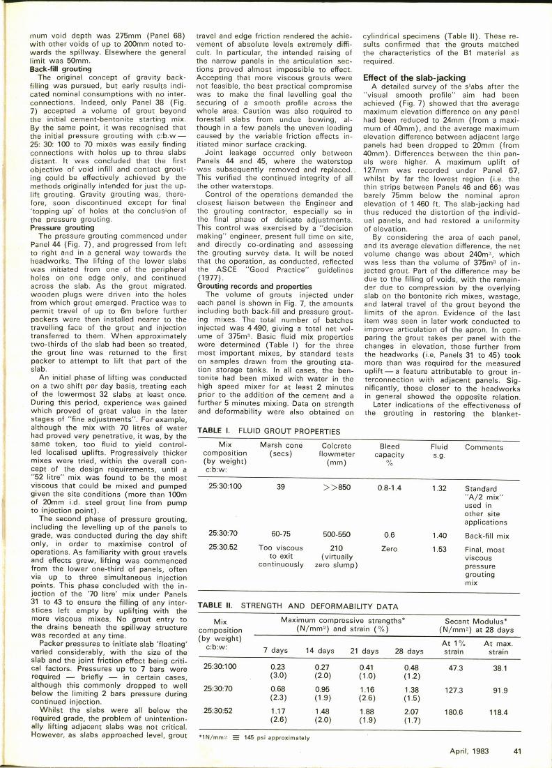
The volume of grouts injected undereach panel is shown in Fig. 7, the amountsincluding both back-fill and pressure grout-ing mixes. The total number of batchesinjected was 4490, giving a total net vol-ume of 375m'. Basic fluid mix propertieswere determined (Table I) for the threemost important mixes, by standard testson samples drawn from the grouting sta-tion storage tanks. In all cases, the ben-tonite had been mixed with water in thehigh speed mixer for at least 2 minutesprior to the addition of the cement and afurther 5 minutes mixing. Data on strengthand deformability were also obtained on
cylindrical specimens (Table II). These re-sults confirmed that the grouts matchedthe characteristics of the B1 material asrequired.
Effect of the slab-jackingA detailed survey of the s'abs after the
"visual smooth profile" aim had beenachieved (Fig. 7) showed that the averagemaximum elevation difference on any panelhad been reduced to 24mm (from a maxi-mum of 40mm), and the average maximumelevation difference between adjacent largepanels had been dropped to 20mm (from40mm). Differences between the thin pan-els were higher. A max'imum uplift of127mm was recorded under Panel 67,whilst by far the lowest region (i.e. thethin strips between Panels 46 and 66) wasbarely 75mm below the nominal apronelevation of 1 460 ft. The slab-jacking hadthus reduced the distortion of the individ-ual panels, and had restored a uniformityof elevation.
By considering the area of each panel,and its average elevation difference, the netvolume change was about 240m', whichwas less than the volume of 375m'f in-jected grout. Part of the difference may bedue to the filling of voids, with the remain-der due to compression by the overlyingslab on the bentonite rich mixes, wastage,and lateral travel of the grout beyond thelimits of the apron. 'Evidence of the lastitem was seen in later work conducted toimprove articulation of the apron. In com-paring the grout takes per panel with thechanges in elevation, those further fromthe headworks (i.e. Panels 31 to 45) tookmore than was required for the measureduplift —a feature attributable to grout in-terconnection with adjacent panels. Sig-nificantly, those closer to the headworksin general showed the oppos'ite relation.
Later indications of the effectiveness ofthe grouting in restoring the blanket-
TABLE I. FLUID GROUT PROPERTIES
Mixcomposition(by weight)c:b:w:
Marsh cone Colcrete Bleed(secs) flowmeter capacity
(mm)
Fluid Commentss.g.
25:30:100 39 ))850 0.8-1.4 1.32 Standard"A/2 mix"used inother siteapplications
25:30:70 60-75 500-550
25:30.52 Too viscous 210to exit (virtually
continuously zero slump)
0.6
Zero
1.40 Back-fill mix
1.53 Final, mostviscouspressuregroutingmix
Mixcomposition(by weight)
c:b:w:
Maximum coinpressivestrengths'N/mm')
and strain (%)
7 days 14 days 21 days 28 days
SecantModulus'N/mm')
at 28 days
At 1%strain
At max.strain
25:30:100
25:30:70
25:30:52
0.23 0.27(3.0) (2.0)
0.68 0.95(2 3) (1 9)1.17 1.48(2.6) (2.0)
0.41(1.0)
1.16(2 6)
1.88(1.9)
0.48(1.2)
1.38(1 5)
2.07(1 7)
47.3
127.3
180.6
38.1
91.9
118.4
*1N/mm" = 145 pal approximately
April, 1983 41
TABLE II. STRENGTH AND DEFORMABILITY DATA
structure continuity were provided as fol-lows:(i) After completion of the slab-jacking.water and grout injection tests were con-ducted on the lower contact of the B1and concrete, through 20 drill holes angledup from ASDGA (Fig. 4). The majorityof the holes were completely water-tightand only the lateral monoliths (5 and 22)had any grout consumptions (58 and 250litres of "A/2 mix" respectively). No openwater paths thus existed along this con-tact. Furthermore, piezometers installed inASDGA after the slab-jacking recordedzero pressure under full reservoir condi-tions, and so confirmed the efficiency ofthe front seal.(ii) At high reservoir, there was a lower-ing of pressure at the heel of the head-works on both sides of up to 1.8m. How-ever, this also can be attributed to con-solidation grouting of the rock done atthe same time as the slab-jacking.(iii) Excavation was conducted duringthe next low reservoir period of certain ofthe thin strips forming the upstream arti-culation and which had proved impossib(eto accurately slab-jack. Grout was foundin intimate contact with the underside ofthe slab, and no void between B1 andgrout could be found.
Summary and conclusionsAn important feature of the auxiliary
spillway remedial works conducted at Tar-bela Dam, Pakistan, in the 1979-80 season,was the slab-jacking of the upstream pro-tective apron. Articulated concrete panelsafforded protection to core material laidon the rock surface, and acting as a blan-ket to reduce hydraulic gradients throughthe rock mass containing karstic lime-stones. Differential settlements of thepanels, however, were linked with voidsforming under the apron and so hadthreatened the integrity of their interlock-ing waterstops.
Injection of 375ms of stable cement-bentonite mixes, into 1 302 holes drilledover the 6130m> area, effectively succeed-ed in restoring the pristine smooth profileof the apron with individual panels beingjacked by over 120mm. Details of thefluid and set mix characteristics were ob-tained for the various designs of groutinvolved.
Further evidence on the effectiveness ofthe operation was provided by (i) subse-quent water and grout tests at the lowerfill-structure interface, (ii) by possibly con-tributing to the reduction in uplift pressuresof the spillway, and (iii) by a later exposi-tion of the panel-grout interface.
Acknowledg erne ntsThis Paper was prepared with the kind
permission of the Pakistan Water andPower Development Authority, Tibbetts-Abbett-McCarthy-Stratton, Indus RiverContractors, and the COL'ROK Joint Ven-ture. Special thanks are also due to Mr.J. Lowe III, Mr. L. H. Hixenbaugh, Dr.D. M. Maitre, Sr. P. G. Ciabarri and Dott. A.Tomiolo.
ReferencesASCE Committee on Groutlng (1977): Slab-jacking—State-of-the-Art. Jour. Geot. Eng Divn., ASCE,GT9 (September) pp. 987-1005.Lowe, J., Chao, P. C. & Luecker, A. R. (1979):"Tarbela Service Spillway Plunge Pool Dev-elopment". Water, Power and Dam Construction,November pp. 85-90.Sza/ay, K. (1975): Dams on Rock Foundations—Some Design Questions II. Proc. Conf, "Rock En-
ineerlng for Foundations and Slopes". Univ. ofolorado, Boulder, August 15-18, Vol. 1 pp.1 14-124.
42 Ground Engineering
W1 ~ 5 (aT> %~3c~
k>j E~ r~ 1 f f ~I~l[gLE~iià L~) i%i i.~.
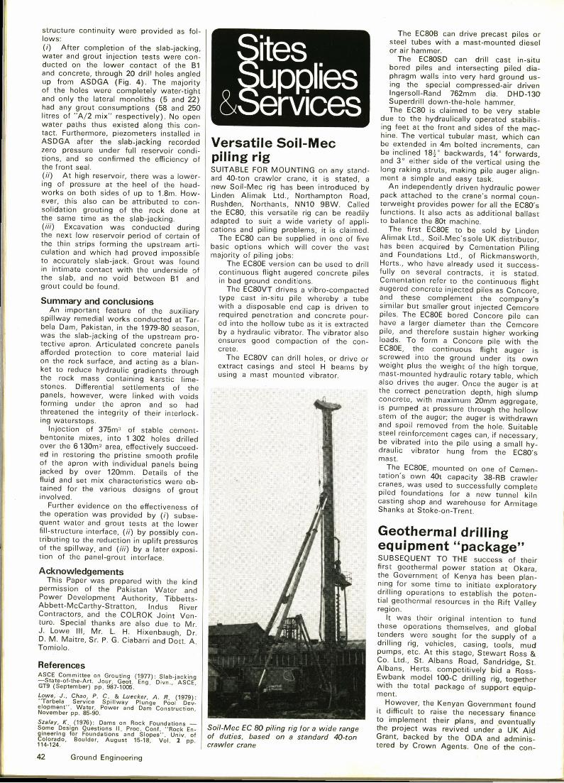
Versatile Soil-Mecpiling rigSUITABLE FOR MOUNTING on any stand-ard 40-ton crawler crane, it is stated, anew Soil-Mec rig has been introduced byLinden Alimak Ltd., Northampton Road,Rushden, Northants, NN10 9BW. Calledthe ECBO, this versatile rig can be readilyadapted to suit a wide variety of appli-cations and piling problems, it is claimed.
The EC80 can be supplied in one of fivebasic options which will cover the vastmajority of piling jobs:
The ECBOE version can be used to drillcontinuous flight augered concrete pilesin bad ground conditions.
The ECBOVT drives a vibro-compactedtype cast in-situ pile whereby a tubewith a disposable end cap is driven torequired penetration and concrete pour-ed into the hollow tube as it is extractedby a hydraulic vibrator. The vibrator alsoensures good compaction of the con-crete.
The EC80V can drill holes, or drive orextract casings and steel H beams byusing a mast mounted vibrator.
Soil-Mec EC 80 piling rig for a wide rangeof duties, based on a standard 40-toncrawler crane
The ECBOB can drive precast piles orsteel tubes with a mast-mounted dieselor air hammer.
The ECBOSD can drill cast in-situbored piles and intersecting piled dia-phragm walls into very hard ground us-ing the special compressed-air drivenIngersoll-Rand 762mm dia. DHD-130Superdrill down-the-hole hammer.The EC80 is claimed to be very stable
due to the hydraulically operated stabilis-ing feet at the front and sides of the mac-hine. The vertical tubular mast, which canbe extended in 4m bolted increments, canbe inclined 18'' backwards, 14 forwards,and 3 either side of the vertical using thelong raking struts, making pile auger align-ment a simple and easy task.
An independently driven hydraulic powerpack attached to the crane's normal coun-terweight provides power for all the ECBO'sfunctions. It also acts as additional ballastto balance the 80t machine.
The first EC80E to be sold by LindenAlimak Ltd., Soil Mec'ssole UK distributor,has been acquired by Cementation Pilingand Foundations Ltd., of Rickmansworth,Herts., who have already used it success-fully on several contracts, it is stated.Cementation refer to the continuous flightaugered concrete injected piles as Concore,and these complement the company'ssimilar but smaller grout injected Cemcorepiles, The ECBOE bored Concore pile canhave a larger diameter than the Cemcorepile, and therefore sustain higher workingloads. To form a Concore pile with theECBOE, the continuous flight auger isscrewed into the ground under its ownweight plus the weight of the high torque,mast-mounted hydraulic rotary table, whichalso drives the auger. Once the auger is atthe correct penetration depth, high slumpconcrete, with maximum 20mm aggregate,is pumped at pressure through the hollowstem of the auger; the auger is withdrawnand spoil removed from the hole. Suitablesteel reinforcement cages can, if necessary,be vibrated into the pile using a small hy-draulic vibrator hung from the EC80'smast.
The ECBOE, mounted on one of Cemen-tation's own 40t capacity 38-RB crawlercranes, was used to successfully completepiled foundations for a new tunnel kilncasting shop and warehouse for ArmitageShanks at Stoke-on-Trent.
Geothermal drillingequipment "package"SUBSEQU'ENT TO THE success of theirfirst geothermal power station at Okara.the Government of Kenya has been plan-ning for some time to initiate exploratorydrilling operations to establish the poten-tial geothermal resources in the Rift Valleyregion.
It was their original intention to fundthese operations themselves, and globaltenders were sought for the supply of adrilling rig, vehicles, casing, tools, mudpumps, etc. At this stage, Stewart Ross &Co. Ltd., St. Albans Road, Sandridge, St.Albans, Herts. competitively bid a Ross-Ewbank model 100-C drilling rig, togetherwith the total package of support equip-ment.
However, the Kenyan Government foundit difficult to raise the necessary financeto implement their plans, and eventuallythe project was revived under a UK AidGrant, backed by the ODA and adminis-tered by Crown Agents. One of the con-