Embed Size (px)
Citation preview
Process ManagementTM
Type OSE
SLAM-SHUT VALVE
Eur
ope,
Mid
dle
Eas
t, A
frica
and
Asi
a P
acifi
c D
ocum
ents
Onl
y
2
Type OSE Slam-Shut Valve
DESCRIPTION
The purpose of the OSE slam shut valve is to totally and rapidly cut off gas fl ow when the outlet pressure exceeds or drops below the setting.
The OSE is equipped with an OS2 release relay. The OS2 has the same essential characteristics as the previous one, a double-stage mechanism, including:
• Accuracy, independent of inlet pressure, flow rate and size of the regulator
• High resistance to shocks and vibrations
• High sensibility to tripping
The following characteristics have been added:
• Visual indication of the first stage position
• Relay tightness (IP 68 (IP 66 for explosion proof and connector box))
• Stainless steel mechanism
• Second stage releasing with electrical contact
• Ergonomical and reset key
• Electrical contact internally protected by the release relay
• Relay cap with possibility of leaded sealing
• Tripping by increasing the maximum pressure (piston detection)
• Possibility of minimum only tripping
Incorporated in the Type OSE DN 25 through 150 is an automatic internal bypasse valve mechanism, which balances pressures on both sides of the plug when resetting. For sizes DN 200 and 250 the bypass is external.
APPLICATIONS
The OSE slam-shut valve serves to provide overpressure and/or underpressure protection in transmission networks, gas distribution systems and gas supply lines for industrial customers. The slam-shut can be used in networks with inlet pressure levels up to 100 bar. It's set range is from 10 mbar to 100 bar. It exists in sizes DN 25 to 250.
BENEFITS
• FlexibilityInterchangeable spring
• SecurityInternal bypass (DN 25 to 150)
• Water TightFunctions in the event of temporary immersion
• High PrecisionTwo-stage tripping mechanism
• Large Tripping RangeInterchangeable box
OPTIONS
• Electrical Remote Sensing:- Explosion proof version with 3-wire connection- Explosion proof version and connector box- Intrinsical safe tight-shut connector
• Second Sensing Box (max and/or min)*
• Manual Push Button Trigger Switch**
• Remote Control with Solenoid Valve
• Additional manometric device for extra pressure sensing
In the case of high pressure applications, there is a choice between :
• Detection by bellows (high accuracy, max and/or min)
• Detection by piston (very high accuracy, max only or min only).
CONNECTIONS
Inlet/Outlet: ISO PN 100B2/50 B1/20 B (ANSI 600/300/150 RF)
Slam-shut sensing line (IS): Tapped 1/4’’ NPT
Slam-shut vent (E): Tapped 1/4’’ NPT
Sensing line (IS): Minimum interior Ø 8 mm
Contact: Type C1 3 m of 3-wire cable Type C2 Explosion proof Type C3 Intrinisical safe
* In this type of confi guration the fi rst sensing box is set at max. only.** Instead of a second sensing box.
Eur
ope,
Mid
dle
Eas
t, A
frica
and
Asi
a P
acifi
c D
ocum
ents
Onl
y
3
Type OSE Slam-Shut Valve
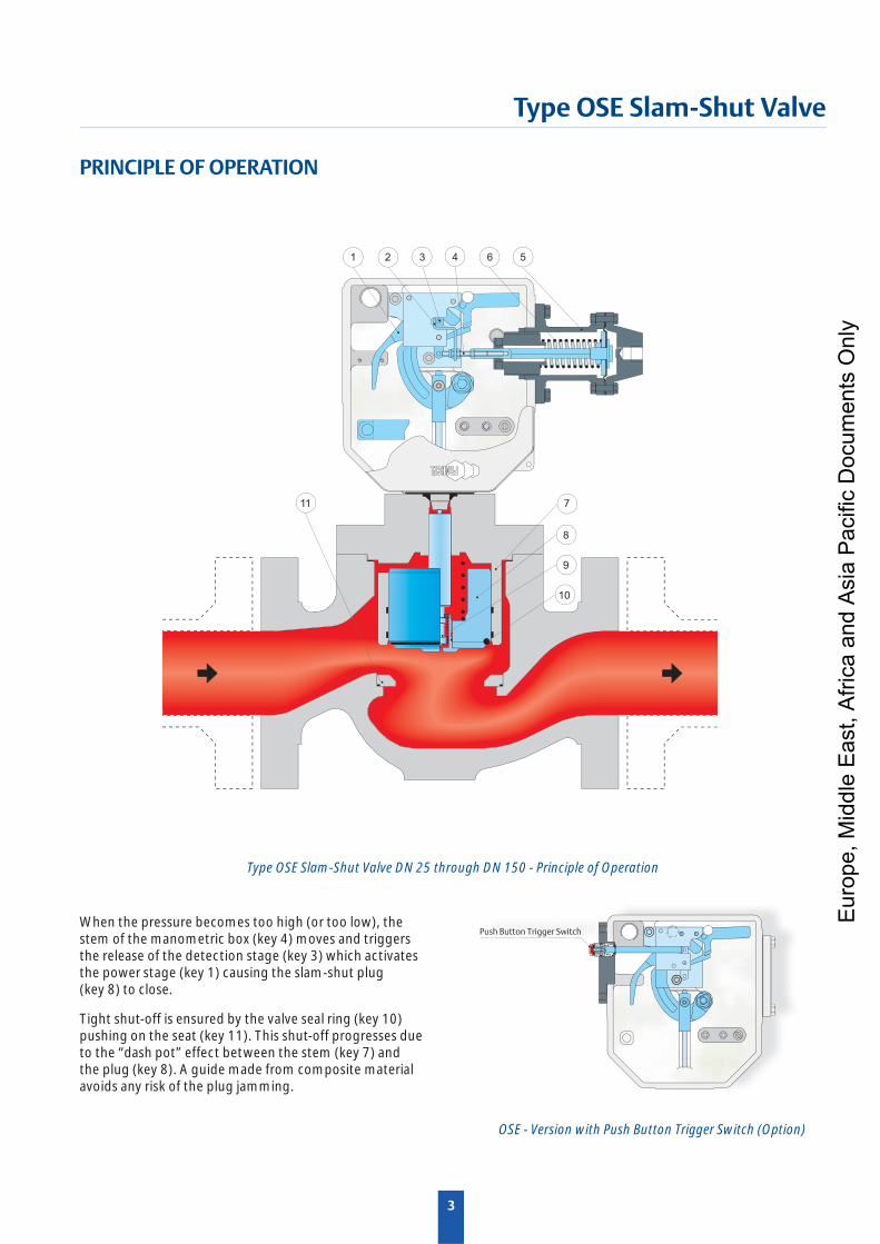
Type OSE Slam-Shut Valve DN 25 through DN 150 - Principle of Operation
7
8
9
10
11
1 2 3 4 6 5
PRINCIPLE OF OPERATION
When the pressure becomes too high (or too low), the stem of the manometric box (key 4) moves and triggers the release of the detection stage (key 3) which activates the power stage (key 1) causing the slam-shut plug (key 8) to close.
Tight shut-off is ensured by the valve seal ring (key 10) pushing on the seat (key 11). This shut-off progresses due to the “dash pot” effect between the stem (key 7) and the plug (key 8). A guide made from composite material avoids any risk of the plug jamming.
Push Button Trigger Switch
OSE - Version with Push Button Trigger Switch (Option)
Eur
ope,
Mid
dle
Eas
t, A
frica
and
Asi
a P
acifi
c D
ocum
ents
Onl
y
4
Type OSE Slam-Shut Valve
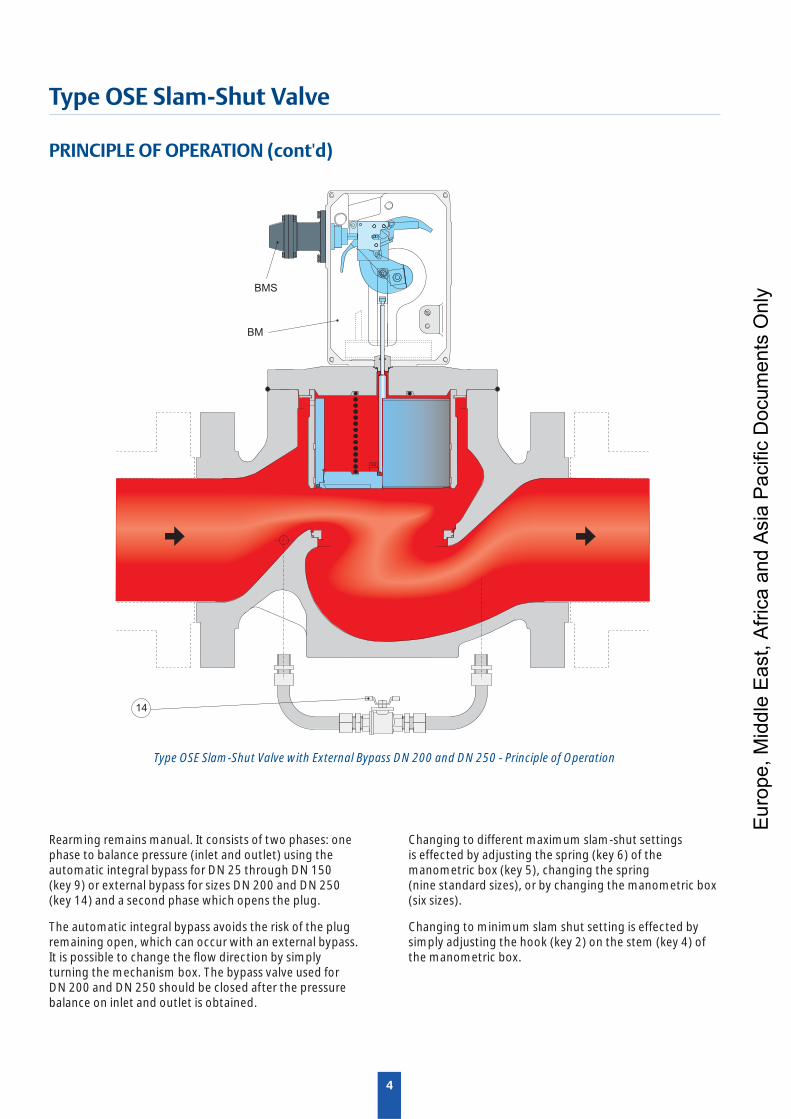
Type OSE Slam-Shut Valve with External Bypass DN 200 and DN 250 - Principle of Operation
PRINCIPLE OF OPERATION (cont'd)
Rearming remains manual. It consists of two phases: one phase to balance pressure (inlet and outlet) using the automatic integral bypass for DN 25 through DN 150 (key 9) or external bypass for sizes DN 200 and DN 250 (key 14) and a second phase which opens the plug.
The automatic integral bypass avoids the risk of the plug remaining open, which can occur with an external bypass. It is possible to change the fl ow direction by simply turning the mechanism box. The bypass valve used for DN 200 and DN 250 should be closed after the pressure balance on inlet and outlet is obtained.
14
BMS
BM
Changing to different maximum slam-shut settings is effected by adjusting the spring (key 6) of the manometric box (key 5), changing the spring (nine standard sizes), or by changing the manometric box (six sizes).
Changing to minimum slam shut setting is effected by simply adjusting the hook (key 2) on the stem (key 4) of the manometric box.
Eur
ope,
Mid
dle
Eas
t, A
frica
and
Asi
a P
acifi
c D
ocum
ents
Onl
y
5
Type OSE Slam-Shut Valve
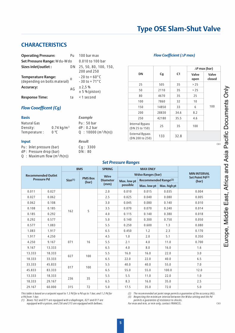
CHARACTERISTICS
Operating Pressure: Pu 100 bar max
Set Pressure Range: Wdu-Wdo 0.010 to 100 bar
Sizes inlet/outlet : DN 25, 50, 80, 100, 150, 200 and 250
Temperature Range: - 20 to + 60° C(depending on bolts materail) - 30 to + 71° C
Accuracy: AG ± 2,5 % ± 5 % (piston)
Response Time: ta < 1 second
Flow Cooefficent (Cg)
Basis
Natural GasDensity: 0.74 kg/m3
Temperature : 0 °C
Example
Pu : 50 bardP : 0.2 barQ : 10000 (m3/h(n))
Input
Pu : Inlet pressure (bar)dP : Pressure drop (bar)Q : Maximum fl ow (m3/h(n))
Result
Cg : 3300DN : 80
This table is based on a setpoint equal to 1.3 Pd for a Pd up to 1 bar, and 1.2 Pd for a Pd from 1 bar.(1) Boxes 162 and 071 are equipped with a diaphragm, 027 and 017 are
equipped with a piston, and 236 and 315 are equipped with bellows.
Recommended Outlet Pressure Pd
BMS SPRING MAX ONLYMIN INTERVALSet Point Pd(3)
(bar)Size(1) PMS Box (bar)
Wire Diameter
(mm)
Wdso Ranges (bar)
Max. low pt possible
Recommended Range(2)
Max. low pt Max. high pt
0.011 0.027
162 5
2.0 0.010 0.015 0.035 0.004
0.027 0.062 2.5 0.025 0.040 0.080 0.005
0.062 0.108 3.0 0.045 0.080 0.140 0.010
0.108 0.185 3.5 0.070 0.070 0.240 0.014
0.185 0.292 4.0 0.115 0.140 0.380 0.018
0.292 0.577 5.0 0.140 0.300 0.750 0.050
0.577 1.083 5.5 0.250 0.600 1.3 0.080
1.083 1.917 6.5 0.450 1.2 2.3 0.170
1.917 4.250
071 16
4.5 1.0 2.0 5.1 0.350
4.250 9.167 5.5 2.1 4.0 11.0 0.700
9.167 13.333 6.5 4.0 8.0 16.0 1.6
13.333 18.333027 100
5.5 16.0 16.0 22.0 3.0
18.333 33.333 6.5 22.0 22.0 40.0 6.5
33.333 45.833017 100
5.5 40.0 40.0 55.0 7.0
45.833 83.333 6.5 55.0 55.0 100.0 12.0
13.333 18.333236 35
5.5 5.5 11.0 22.0 1.0
18.333 29.167 6.5 8.3 16.0 35.0 2.5
29.167 60.000 315 72 5.0 17.5 35.0 72.0 5.0
C63
Flow Coefficient (∆P max)
C61
DN Cg C1
∆P max (bar)
Valve open
Valve closed
25 505 35 > 25
100
50 2110 35 > 25
80 4670 35 25
100 7860 32 10
150 14850 33 6
200 28830 34.6 8.2
250 42180 35.5 4.6
Internal Bypass (DN 25 to 150)
25 35 100
External Bypass (DN 200 to 250)
133 32.8
Set Pressure Ranges
(2) The recommended set point range permits a guarantee of the accuracy (AG).(3) Respecting the minimum interval between the Wdso setting and the Pd
permits a guarantee of resistance to shocks.For max and min, or min only, contact FRANCEL.
Eur
ope,
Mid
dle
Eas
t, A
frica
and
Asi
a P
acifi
c D
ocum
ents
Onl
y
6
Type OSE Slam-Shut Valve
Pu Pd
EIS
C65
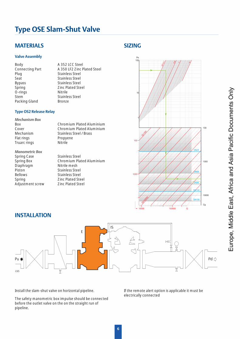
MATERIALS
Valve Assembly
Body A 352 LCC SteelConnecting Part A 350 LF2 Zinc Plated SteelPlug Stainless SteelSeat Stainless SteelBypass Stainless SteelSpring Zinc Plated SteelO-rings NitrileStem Stainless SteelPacking Gland Bronze
Type OS2 Release Relay
Mechanism BoxBox Chromium Plated AluminiumCover Chromium Plated AluminiumMechanism Stainless Steel / BrassFlat rings PropyeneTruarc rings Nitrile
Manometric BoxSpring Case Stainless SteelSpring Box Chromium Plated AluminiumDiaphragm Nitrile meshPiston Stainless SteelBellows Stainless SteelSpring Zinc Plated SteelAdjustment screw Zinc Plated Steel
100
Q=1
0000
Q=1
00
100
1000
1000
10000
100000
10
100
Pe
10000
1
Cg
Q
1 5
dP
=0,1
DN50
DN150
DN100
DN80
DN25
0,5
SIZING
INSTALLATION
Install the slam-shut valve on horizontal pipeline.
The safety manometric box impulse should be connected before the outlet valve on the on the straight run of pipeline.
If the remote alert option is applicable it must be electrically connected
Eur
ope,
Mid
dle
Eas
t, A
frica
and
Asi
a P
acifi
c D
ocum
ents
Onl
y
7
Type OSE Slam-Shut Valve
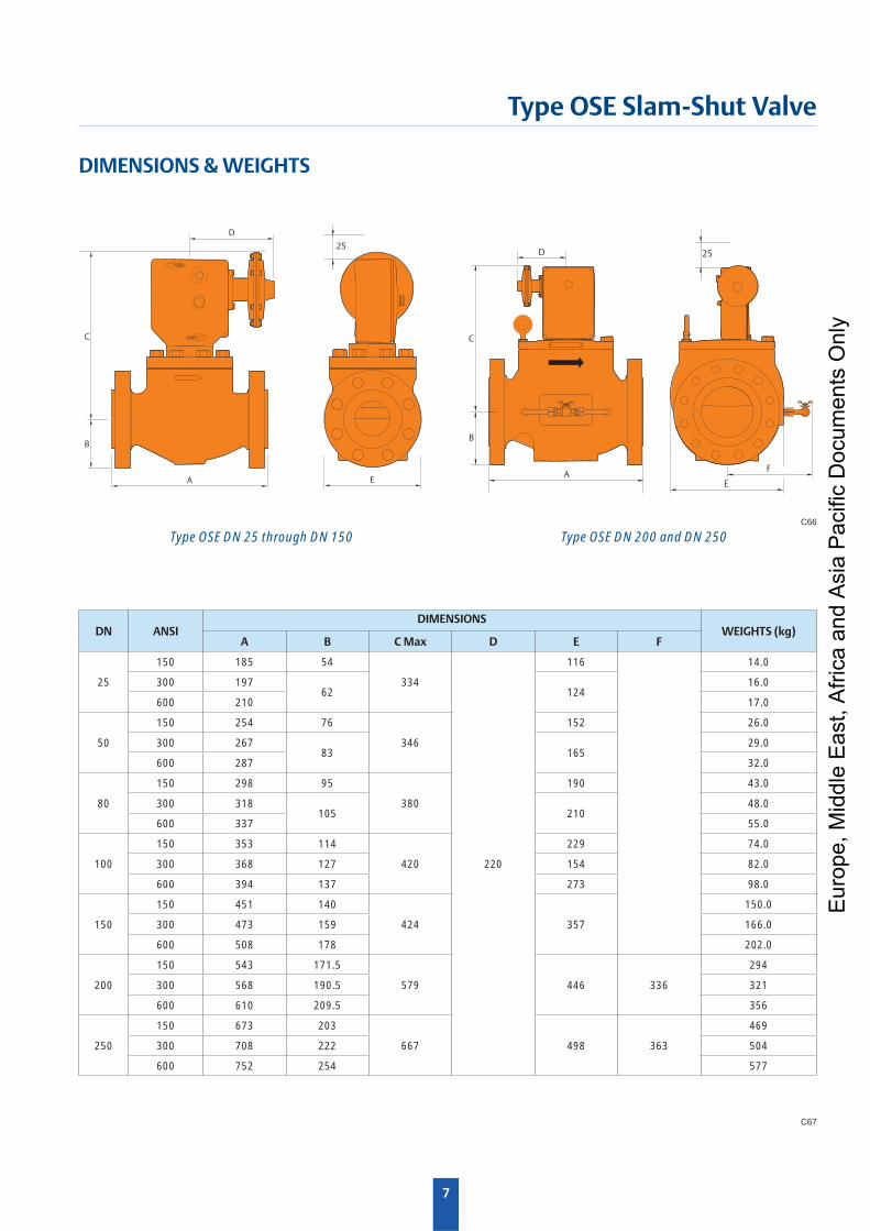
DIMENSIONS & WEIGHTS
C
B
A
D
25
E
C67
DN ANSIDIMENSIONS
WEIGHTS (kg)A B C Max D E F
25
150 185 54
334
220
116 14.0
300 19762 124
16.0
600 210 17.0
50
150 254 76
346
152 26.0
300 26783 165
29.0
600 287 32.0
80
150 298 95
380
190 43.0
300 318105 210
48.0
600 337 55.0
100
150 353 114
420
229 74.0
300 368 127 154 82.0
600 394 137 273 98.0
150
150 451 140
424 357
150.0
300 473 159 166.0
600 508 178 202.0
200
150 543 171.5
579 446 336
294
300 568 190.5 321
600 610 209.5 356
250
150 673 203
667 498 363
469
300 708 222 504
600 752 254 577
C66
C
B
A
D
E
F
25
Type OSE DN 25 through DN 150 Type OSE DN 200 and DN 250
Eur
ope,
Mid
dle
Eas
t, A
frica
and
Asi
a P
acifi
c D
ocum
ents
Onl
y
The Emerson logo is a trademark and service mark of Emerson Electric Co. All other marks are the property of their prospective owners. Francel is a mark owned by Francel SAS, a business of Emerson Process Management.
The contents of this publication are presented for informational purposes only, and while every effort has been made to ensure their accuracy, they are not to be construed as warranties or guarantees, express or implied, regarding the products or services described herein or their use or applicability. We reserve the right to modify or improve the designs or specifi cations of such products at any time without notice.
Emerson Process Management does not assume responsibility for the selection, use or maintenance of any product. Responsibility for proper selection, use and maintenance of any Emerson Process Management product remains solely with the purchaser.
NCAOSE0310EN-OSE-BUL-01/2013©Francel, 2010, 2013; All rights reserved
Type OSE Slam-Shut Valve
Industrial Regulators
Emerson Process Management Regu-lator Technologies, Inc.
USA - HeadquartersMcKinney, Texas 75069-1872, USATel: +1 800 558 5853Outside U.S. +1 972 548 3574
Asia-Pacifi cShanghai 201206, ChinaTel: +86 21 2892 9000
EuropeBologna 40013, ItalyTel: +39 051 419 0611
Middle East and AfricaDubai, United Arab EmiratesTel: +971 4811 8100
For further information visit www.Francel.com
Natural Gas Technologies
Emerson Process Management Regulator Technologies, Inc.
USA - HeadquartersMcKinney, Texas 75069-1872, USATel: +1 800 558 5853Outside U.S. +1 972 548 3574
Asia-Pacifi cSingapore 128461, SingaporeTel: +65 6777 8337
EuropeO.M.T. Tartarini s.r.l. Via P. Fabbri 1, I-40013 Castel Maggiore (Bologna), ItalyTel: +39 051 419 0611Francel SAS, 3 ave Victor Hugo, CS 80125 Chartres 28008, FranceTel: +33 2 37 33 47 00
TESCOM
Emerson Process ManagementTescom Corporation
USA - HeadquartersElk River, Minnesota 55330-2445, USATels: +1 763 241 3238 +1 800 447 1250
Asia-Pacifi cShangai 201206, ChinaTel: +86 21 2892 9499
EuropeSelmsdorf 23923, GermanyTel: +49 38823 31 287 E
urop
e, M
iddl
e E
ast,
Afri
ca a
nd A
sia
Pac
ific
Doc
umen
ts O
nly