Embed Size (px)
Citation preview

1
2
3
4
5
6
7
Type selection is in accordance with the construction and with diameter and quantity of the lines to be installed. A clearance of at least 10 % for cables and 20 % for hoses should be available.
The R(adius) is also dependent on the lines to be installed. Comply with the statements of the manufacturer. Normally the chain bend radius should be 10 times the largest cable diameter.
The Length of the chain depends on the travel distance and can be calculated with the following formula:L = travel distance / 2+ 4 x radius (rounded up to link pitch)
The Width of the chain (stay length+2d) depends on the number and cross section of the cables to be installed. With slow applications cables can be installed on top of one another, creating extra space (see separator options).
The Connectors depend on the application in question. Where required the connection angle can be slightly modified.
The Arrangement is only to be stated in special cases. (see page 29)
The Separator arrangements depend on the application (see order example or separator options).
individual solutionslarge dimensionssimple handling
SLE Energy chains
0.5 x travel distance Lv
moveable connector
fixed connector (mid travel distance)
supporting surface
ca.0.5xR
R
length L
pitch
pretension: 5mm/m
0.5 x travel distance Lv
1
Note: Indicate arrangement (page 29),load and strokes per minute at order!Consider minimum bend radii of the cable and tube manufacturers.Lengthening and shrinking of up to 4% is possible at hydraulics tubes.
Material:Energy guideway chain SLE is supplied as standard in steel. For aggressive environments the chain can be executed in stainless steel (e.g. off-shore). The use of hardened chains with large bend radii is necessary for high travel speeds (>1m/s) and accelerations (>4m/s²).
ca.0.5xR
R
chain width + 50
2 x
R +
link
heig
ht
50 m
in.
The order for a steel chain SLE should contain the following data:
Type / Radius x Length / Width - Connector “Arrangement”; Separator arrangement
Example: travel distance 3 m, bend radius 200 mm, cables: 1x15 mm, 8 x 8 mm, 3 x 12 mm, 2 x 22 mm; the chain is hanging (see page 29)
SLP 220 / 200 x 2325 / 200 - D/E “h“; 5 PZ, 1 PT55
1PT 55 5 PZ
ekd g
ele
nkro
hr
Gm
bH
-
tele
phone +
49(0
)211 / 2
49040 -
tele
fax +
49(0
)211 / 2
41088

12
g
f
h
k
d
SLE 225 SLE 325SLE 525SLE 625
SLE 121 SLE 221 SLE 321SLE 521SLE 621
SLE 128 SLE 228 SLE 328SLE 528SLE 628
SLE 120 SLE 220 SLE 320SLE 520SLE 620
c
5 d
a
8
7,5 > 5e
Normal connector connector A connector B connector Cin outer radius in outer radius
connector E connector Din inner radius in inner radius
stay
length
stay
length
standard types
stay in each link
closed types
option with sliders
SLE Separator options and dimensions
max. usable width = stay length -15 mm; chain width = stay width + 2 x dother radii on request
stay
length
stay
length
bend radius pitch weight [kg/m]R a c d e f g h k (stay 100)
SLP 120 60 / 100 / 150 / 250 50 20 35 5,5 3 20 7,5 7 9,5 2,30
SLE 220 5,00SLS 220 100 / 150 / 200 75 31 50 8 4 30 12 9 15 4,90SLP 220 250 / 300 4,80SLA 220 5,50
SLE 320 9,30SLS 320 150 / 200 / 250 100 49 75 10 4 50 17 11 21 9,10SLP 320 300 / 400 9,10SLA 320 10,00
SLE 520 18,40SLS 520 200 / 250 / 300 125 68 100 14 4 70 22 13 28 18,10SLP 520 400 / 500 18,10SLA 520 19,30
SLP 620 250 / 300 / 400 175 118 150 14 8 115 26 13 32 25,00
SLE (stay with plastic inserts) SLS (foam stay) SLP (plastic intermediate divider) SLA (aluminium stay)
2
ekd
ge
len
kro
hr
Gm
bH
-
te
lep
ho
ne
+4
9(0
)211
/ 2
49
04
0 -
te
lefa
x +
49
(0)2
11
/ 2
41
08
8

PT 55 55 up to 80 PT 75 75 up to 100
SLE Stay and Separator options
SLA (SLE with aluminium profile) is an individual and sturdy energy chain which is specially chosen for use with large dimensions.The stays are created according to the users specifications.
SLE (SLE with inserts) guarantees ideal guidance with high travel speeds and protects against ruling out errors when installing cables.
SLE available inserts Ø [ mm ]
220 10 15 20 25 30 320 10 15 20 25 30 35 40 45 50 520 10 15 20 25 30 35 40 45 50 55 60 65 70
In the case of restricted installation space SLS (SLE with foam separator) should come in use. Here too, optimized guidance is guaranteed at high speeds and accelera-tions. Well known car manufacturers are using this version for many years with great success.
Where this is not possible for reasons of space, the SLP (SLE with with plastic intermediate separators PZ and additional distribution possibilities) can be selected. This low cost version permits the reliable guidance of large numbers of cables. The highly variable divider distribution possibility due to the small step of (3 mm) in the height setting range, plus the telescopic layer divider (PT) permit maximum distribution for all requirements, also in the case of retrospective changes.
The SLA, SLE or SLS variants should take preference for extreme applications, as these offer maximum guidance for the cables. Note that it is imperative to avoid multi-layer arrangement of the cables with high speeds and accelerations.
SLE with inserts
SLA with aluminium profile
aluminium - T- profile
foam stay
plastic inserts (PE)[alternative: push in profile]
plastic intermediatedivider (PZ)
plastic intermediatedivider, short (PK)
plastic telescopiclayer divider (PT)
plastic layer divideroverhung (PF)
SLS with foam
SLP with plastic intermediate separators (PZ)
Compared to standard chains the SLE series is characterized by the fact that the sturdy aluminium profile can be steplessly adapted to the requirement. Stay length of up to 1500 mm can be realized. The subdivision of the interior satisfies every requirement and guarantees optimized cable protection, even at very high accelerations and travel speeds.
plastic telescopic layer divider (PT)
range in mm
3
ekd
ge
len
kro
hr
Gm
bH
-
te
lep
ho
ne
+4
9(0
)211
/ 2
49
04
0 -
te
lefa
x +
49
(0)2
11
/ 2
41
08
8

SLE up from R
225 100325 150525 200625 300
band holder
outer band
inner bandend fastening
SLE Covers
Stainless steel cover:
For cable protection against outside damaging and against dust and sharp shavings spring steel bands can be placed inside and outside. The bands have rounded edges to prevent accidents.
very good visual impression
stay spacing which has proved its value for 25 years
very rigid, solid cable protection up to 1.500 mm wide
opening possible at any point of the energy chain
existing chains can be updated with silver star
band holder
outer band
inner bandend fastening
SLE 320/ 200 x 2100 /200 "h"with stainless steel covers (inner and outer)
SLE 325/ 200 x 2100 /200 "h"
Abdeckung
Stars for the cover
normal stay cover
SLE Covers
SLE 320/ 200 x 2100 /200 "h"with stainless steel covers (inner and outer)
Example:
SLE 325/ 200 x 2100 /200 "h"
Example:
Abdeckung
Stars for the cover
normal stay cover
4
ekd
ge
len
kro
hr
Gm
bH
-
te
lep
ho
ne
+4
9(0
)211
/ 2
49
04
0 -
te
lefa
x +
49
(0)2
11
/ 2
41
08
8

320320
032032
320 320
302302
320320
320320
320 320
20 320 3
type identificationin inner radius
320320
032032
type identification in outer radius
SLE 120 220 320 520 620
Radius 60 100 150 200 250
Radius 100 150 200 250 300
Radius 150 200 250 300 400
Radius 250 250 300 400 500
Radius 300 400 500 600
1
4
2
3
5
Normal connectorNormal connector
4
2
Normalconnector C
BA
Normalconnector C
BA
normal assembly
quick assembly
normal assembly
quick assembly
SLE Assembly information
type designation
stamped radii designation [cm]
connector link(double forked)
5
Shortening or lengthening of the chain:
Remove the cir clips (1), take off the cover plates (3), remove the shoulder pin (2) and socket pins (4). Remove or add links (5) and stays. Push the links together, insert the middle bolt (2), form radius by means of the socket pins (see table) and refit cover plates (3).
Changing the bend radius :
Remove the cir clips (1), take off the cover plates (3). Change over the socket pins (4) according to the table. Refit the cover plates (3).
Note: The assembly scheme for the different radii is stamped on the double end connector link.
Repositioning connection angles:
The connection angle can be both inside and outside the chain in the inner and outer radius. Normally the connectors are inside the chain, facing the other radius. The connection angle can be brought to any position by removing the circlip (see above).
Stay disassembly:
The stays are very simple to remove by unscrewing the four hexagon screws. Quick-assembly is an alternative possibility where only two screws have to be removed. Stays with quick-assembly may be ordered according to drawing 4-2288.
type designation
stamped radii designation [cm]
connector link(double forked)
(The smallest radius is build with 2 socket pins only)
ekd
ge
len
kro
hr
Gm
bH
-
te
lep
ho
ne
+4
9(0
)211
/ 2
49
04
0 -
te
lefa
x +
49
(0)2
11
/ 2
41
08
8

1
2
0,5 travel distance
F0,25 travel distance
0,5 travel distance
R
B
2R
+m
ax.
5 m
m
6
Support rollers enable longer travel distances and offer optimal guidance of the energy chain. They can be used whenever the travel distance exceeds twice of the the unsupported free carrying length of the chain. The order for a support roller SR should contain the following data:
SR width of supp. surface [cm] / Ø100 x height
The width of the supporting surface (A)depends on the stay width of the steel chain in use (see table).
The height (H) of the support bracketdepends on the radius of bend of the steelchain in use.
Example: bend radius 150mm, stay length 115mm
SR 15 / Ø 100 x 300
LOAD DIAGRAM SLE
B
Ø100
A
Ø120
Ø10,5
100
120
50
6
C
D
50
heig
ht (
2 x
R o
r as
speci
fied)
SLE Support brackets and support rollers
energy chain SLE with two support rollers and support brackets:maximum travel distance = 4 x free carrying length
SR A B C D max. other sizes on request stay length
10 100 166 80 140 65
15 150 216 130 190 115
20 200 266 180 240 165
25 250 316 230 290 215
30 300 366 280 340 365
35 350 416 330 390 315
40 400 466 380 440 365
45 450 516 430 490 415
50 500 566 480 540 465
55 550 616 530 590 515
60 600 666 580 640 565
65 650 716 630 690 615
70 700 766 680 740 665
75 750 816 730 790 715
ekd
ge
len
kro
hr
Gm
bH
-
te
lep
ho
ne
+4
9(0
)211
/ 2
49
04
0 -
te
lefa
x +
49
(0)2
11
/ 2
41
08
8

13
stay length + v
stay length
10
35
3 30°
chain width + 20
chain width =
stay length + 2x d
14
50
50
channels angle:length 3 m
7
SLE220320520620
v44465050
SLE Accessories
Support channels:
Support channels comprise as standard 2 angular channels in 3 m length. They are used where precise guidance of steel chains is required.
Important for assembly: Weld channels together smoothly without offset, clean off the welds. There must be no projections over the entire chain support area (e.g. screw heads, nuts, pins etc.).
Sliders:
Sliders are combined with types 128, 228, 328, 528, and 628 at long travel distances when the upper part of the chain moves on the lower part. The sliders are assembled in the inner radius. The slider surface is extremely smooth (friction coefficient µ=0,2 up to 0,25). After lifetime the sliders can be exchanged and the energy chain can be used furthermore.
Slide plates:
Slide plates are used with steel chains in "w" arrangement (laying horizontally on the side) for long travel distances and "k" arrangement (circular).The slide plates are made of high grade, highly abrasive resistance plastic (or other materials upon request). Guidance is necessary with both arrangements.
Shouldered guide rollers:
The shouldered guide rollers are used with overlong chains with support rails in combination with support rollers and support brackets (drawing 1-1717).
Guide rollers:
Instead of a steel chain with support rollers, guiderollers can be mounted in the steel chain. In that case the guide rollers rest on a supporting rail.(Note: Supporting rail length min.1/4 travel distance).
Support carriage:
Steel chains with support carriages are employed with long travel distance and very high additional weights as "contra running" chain configurations. The chains rest on the support carriage with laterally mounted shouldered guide rollers.
Technical characteristics:
- only tensile forces- long travel distances- extreme additional loads- easy running, long life
ekd
ge
len
kro
hr
Gm
bH
-
t
ele
ph
on
e +
49
(0)2
11
/ 2
49
04
0 -
te
lefa
x +
49
(0)2
11
/ 2
41
08
8

0.5 x travel distance
moveable connector
fixed connector (mid travel distance)
supporting surface
ca.0.5xR
R
length Lpretension: 5mm/m
pitch
0.5 x travel distance
chain width + 50
2 x
R +
link
heig
ht
50 m
in.
The order text for a steel chain type GKA should contain the following data:
Type / Radius x Length / Width - Connector "Arrangement"; Separator arrangement
Type selection is in accordance with diameter and quantity of the lines to be installed. A clearance of at least 10 % for cables and 20 % for hoses should be available.
The R(adius) is also dependent on the lines to be installed. Comply with the statements of the manufacturer. Usually 10 times the largest cable diameter can be taken.
The Length of the chain depends on the travel distance. The following formula can be used: L = travel distance / 2+ 4 x radius (rounded up to link pitch)
The Width of the chain depends on the number and cross section of the cables to be installed. With slow applications cables can be installed on top of one another, creating extra space.
The Connectors depend on the application in question. Where required the connection angle can be slightly modified.
The Arrangement is only to be stated in special cases. (see page 29)
The Separator arrangement depend on the application. If possible arrange the weight evenly across the stays, heaviest cables and tubes quiet close to the link strands.
Example:travel distance 9.350 mm; bend radius 1.000 mm; pitch 225mm (GKA 160)installation: 2 tubes 100; 4 cables 37,3; 4x 24; 2x 10,3 a) theoretical chain length: 9.350 /2 + 4x 1.000 = 8.675 b) calculation of the number of links: 8.675 / 225 = 38,55 (chose 39 links)c) order length 39 x 225 = 8.775
GKA 160 / 1.000 x 8.775 / 660 - D/E
Material:Energy chain GKA is supplied as standard in galvanized steel. For aggressive environments the chain can be executed in stainless steel( eg. off-shore).The use of hardened chains with large bend radii is recommended for high travel speeds and accelerations.
GKA Energy chains
1
2
3
4
5
6
7
8
ekd
ge
len
kro
hr
Gm
bH
-
t
ele
ph
on
e +
49
(0)2
11
/ 2
49
04
0 -
te
lefa
x +
49
(0)2
11
/ 2
41
08
8

Normal connector connector A connector B connector Cin outer radius in outer radius
connector E connector Din inner radius in inner radius
0,5 travel distance 0,5 travel distance
movable connector
fixed connector
supporting surface
pitch
R
j
c
f min. 25chain width
t=
2
0
heig
h
R
+c
+ 1
5
13,5 stay length 13,5
min. 7,5
GKA - aluminium stay GKP - plastic intermediate divider
12
Ø8
a
GKR - rods
c
8 (PZ only GKP110)12 (alu intermediate divider)
Ø8
GKA bend radiusR (min)
pitch free carrying length weight [kg/m]500mm staya c f j m kg /m
110 200 175 118 150 110 2308,5 25
25
160 30
210 300 275 218 250 210 3709,5 30
40
260
310 375 318 350 310 500 11 40 55
360 65
410 475 418 450 410 620 12 45 75
460
225
325
425
525
168 200 160 300
268 300 260 430
368 400 360 560
468 500 460 680
45
85
250
300
400
450
550
600
700
GKA Dimensions
f
stay
length
The bending radius is acc. to consultation freely eligible (notice polygon effect)Stay variants and connectors can differ from these representations. Energy chains GKA will be produced individually in arrangement with the customer.
9
ekd g
ele
nkro
hr
Gm
bH
-
tele
phone +
49(0
)211 / 2
49040 -
tele
fax +
49(0
)211 / 2
41088

SFK Radius a b c d g k p z weight
kg/m
12 N 75 / 100 25 46 30 50 20 28 56 45 2,0
12 H 100 / 150 46 46 50 50 20 28 76 75 2,5
12 S 75 26 26 30 30 0 28 56 45 1,2
22 N 100 / 150 40 79 45 85 50 30,5 71 65 3,0
22 H 150 / 200 56 80 60 85 50 30,5 86 90 3,5
22 S 200 78 78 85 85 50 30,5 111 130 5,1
32 N 150 / 200 54 109 60 115 80 30,5 86 90 4,8
32 H 200 / 250 75 110 80 115 80 30,5 106 120 5,3
32 S 300 109 109 115 115 80 30,5 141 175 6,6
52 N 200 / 250 74 169 80 175 140 30,5 106 120 7,5
52 H 250 / 300 103 170 110 175 140 30,5 136 170 8,2
52 S 350 170 170 175 175 140 30,5 201 270 9,2
Example: max. travel distance 3 m, bend radius 100 mm, normal arrangement
SFK 32N / 100 x 1900 / N/N
type / radius x length / connectors / arrangements
SFK Energy tubes
Bestelllänge L
R
(z)
order length L
order length L = straight length + z (z see table)
R
(z)Order length is half of travel distance plus four times bend radius:
L = Lv/2 + 4 R order length L
d
c
b
a
g
2
609
15
tube length
Norm flange2
10
ekd
ge
len
kro
hr
Gm
bH
-
te
lep
ho
ne
+4
9(0
)211
/ 2
49
04
0 -
te
lefa
x +
49
(0)2
11
/ 2
41
08
8

g
taper flange
60
120
94010
LOAD DIAGRAM SFK
dg
)lo
a / (
k/m
free carrying length Lf / (m)
8
6
4
2
0 3 2 1
SK
22
F
2S
FK
3
F2
SK
5
0
10
SFK 12
g
connector A p
9 8
3
connector N
g60
9
15
connector B
g
20
k
SFK Qualities
The tube consists of a rectangular, galvanized steel corrugated tube and a spring steel ribbon retracted in the inside radius. SFK offers optimal line protection at low outside dimensions. The SFK is excellently suitable at short free carrying lengths in areas with spark flight and entry of hot shaving.The temperature field of application is between -40° and +180° of celsius.
SFK Connectors
Connector N
The reasonably priced norm flange N is standard with four drillings each.
Connector A
With lowering screws, knurled nuts and angles (Zng. 4-2594) the norm flange turns to the connector A.
Connector B
Connector B has angles at the side. The drillings of the norm flange are dropped.
Taper flanges Taper flanges complete the number of possible connectors.
configuration 1 configuration 2 configuration 3 2 x outer radius 1 x outer radius 2 x inner radius
1 x inner radius
Example:
SFK 32N / 250 x 3000 / N N / "h"type / radius x length / connectors / arrangement
SFK Connectors
Example:
SFK 32N / 250 x 3000 / A A / "h"type / radius x length / connectors / arrangement
Example:
SFK 32N / 250 x 3000 / B B / "h"type / radius x length / connectors / arrangement
Example:
SFK 32N / 250 x 3000 / S1 / "h"type / radius x length / connectors / arrangement
k
11
ekd
ge
len
kro
hr
Gm
bH
-
t
ele
ph
on
e +
49
(0)2
11
/ 2
49
04
0 -
te
lefa
x +
49
(0)2
11
/ 2
41
08
8

b
d
b
d
a c
PFR Energy tubes
pretension: 25mm/mPFR 322: 20mm/mPFR 323: 20mm/m
0.5 x travel distance
moveable connector
fixed connector
support surface
ca.0.5xR
R
length Lpretension
pitch
PFR 123, 223, 323
PFR 121,122, 221, 222, 322
PFR disassembly
The thorns (3 x12mm) of the dismantling tools are put apart at the side, the dismantling tools are pressed together and the links are pulled from each other.
PFR Radius pitch a b c d g h i k kN p pN w weight
kg/m
121 75 / 100 35 23 23 35 35 0 5 9 5,5 61 25 61 20 0,7
122 75 / 100 35 23 38 35 50 20 5 9 5,5 56 25 61 20 1,2
123 75 / 100 35 23 30 35 75 45 5 9 5,5 56 25 61 20 1,5
221 100 / 200 50 34 36 50 50 20 6 11,5 4,5 56 40 76 25 1,6
222 100 / 200 50 34 86 50 100 70 6 11,5 4,5 56 40 76 25 2,1
223 100 / 200 50 34 66 50 150 120 6 11,5 4,5 56 40 76 25 2,8
322 150 / 300 65 57 134 75 150 120 8 15 3,5 56 65 101 35 3,2
323 150 / 300 65 57 103 75 225 195 8 15 3,5 56 65 101 35 4,6
Example: travel distance 3 m, bend radius 200 mm, plastic end connectors, configuration hanging
PFR 222 / 200 x 2300 / KK "h"
type / radius x length / connectors arrangement
12
ekd
ge
len
kro
hr
Gm
bH
-
t
ele
ph
on
e +
49
(0)2
11
/ 2
49
04
0 -
te
lefa
x +
49
(0)2
11
/ 2
41
08
8

LOAD DIAGRAMPFR
oa
dg
)l
/ (
k/m
free carrying length Lf / (m)
8
6
4
2
0 3 2 1
PF
R 1
22
P
2F
R22
F3
PR
22
0
10
PFR Connectors
PFR Characteristics
The PFR offers very good line protection against dama-ges, pollutions and shaving or like that by the closed design. PFR 123, 223 and 323 leads the lines in two separate chambers.PFR with a metallized surface is an ekd speciality which mainly is used in applications with hot shaving or spark flight.
PFR plastic end connector
The plastic end connector (K) can be installed in every arbitrary position of the tube, so a part of the tube can serve as a fixed line.
Example: plastic end connector at both ends
PFR 121 / 75 x 1505 / K K
type / radius x length / connectors
PFR front flange connector
The front flange connector (SFA) is used at assembly in front of head of the machine. A combination of front flange connector and plastic end connector is possible.
Example: plastic end connector and front flange connector
PFR 121 / 75 x 1505 / K SFA
type / radius x length / connectors
Steel connector
(Steel connectors only on request)
Example: connector N and connector A
PFR 121 / 75 x 1505 / N A
type / radius x length / connectors
PFR PFR metallized
k
p
5
w
L
g
connector Bg
9
20
kN
connector A
pN
g9
8
3
connector N
g609
15
L
g
hL
L= tube length
i
13
ekd
ge
len
kro
hr
Gm
bH
-
te
lep
ho
ne
+4
9(0
)211
/ 2
49
04
0 -
te
lefa
x +
49
(0)2
11
/ 2
41
08
8

1
2
3
4
5
6
Type selection is in accordance with the construction and with diameter and quantity of the lines to be installed. A clearance of at least 10 % for cables and 20 % for hoses should be available.
The R(adius) is also dependent on the lines to be installed. Comply with the statements of the manufacturer. Normally the chain bend radius should be 10 times the largest cable diameter.
The Length of the chain depends on the travel distance and can be calculated with the following formula: L = travel distance / 2+ 4 x radius (rounded up to link pitch)
The Width of the chain (stay length+2d) depends on the number and cross section of the cables to be installed. With slow applications cables can be installed on top of one another, creating extra space (see separator options).
The Arrangements is only to be stated in special cases (see page 29).
The Separator arrangement depend on the application.
14
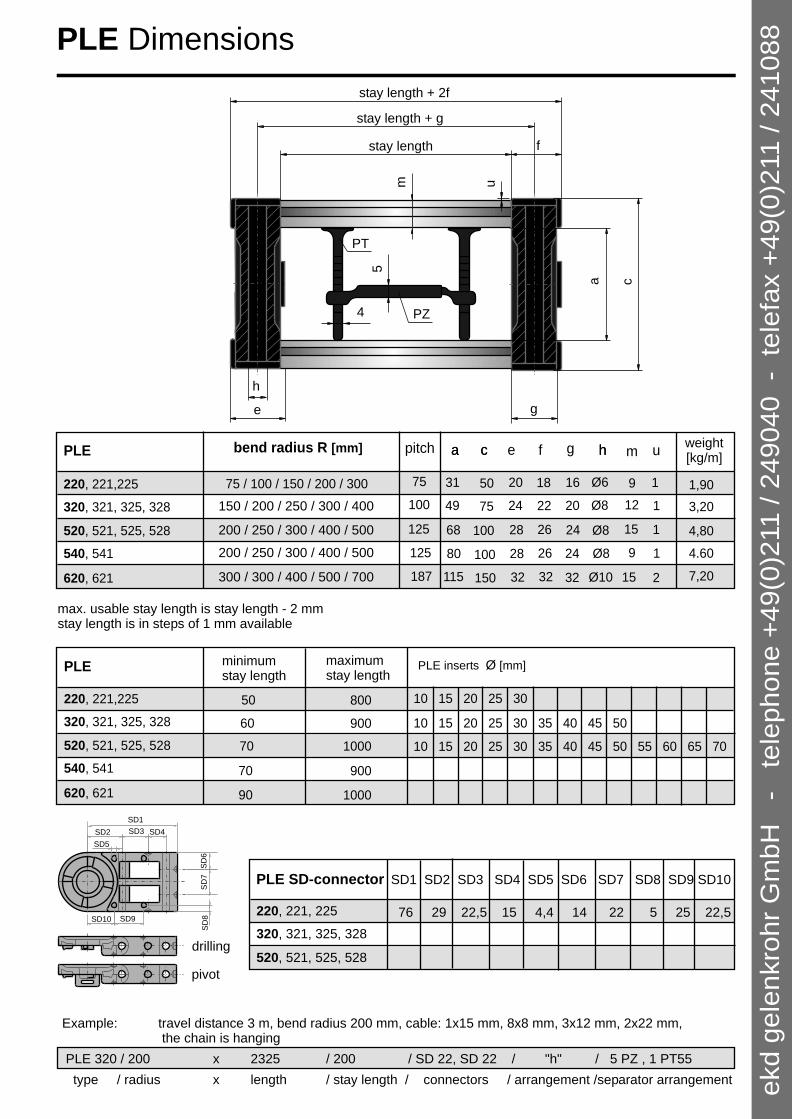
The order for an energy chain PLE should contain the following data:
Type / Radius x Length / Width - Connector "Arrangement"; Separator arrangement
Example: travel distance 3 m, bend radius 200 mm, cables: 1x15 mm, 8 x 8 mm, 3 x 12 mm, 2 x 22 mm; the chain is hanging 1 PT55 5 PZ
PLP 220 / 200 x 2325 / 200 - D/E “h“; 5 PZ, 1 PT55
Note: Indicate configuration (p.29), load and strokes per minute at order ! Take minimum bend radii of the cable and tube manufacturers into account. Stretching and shrinking of up to 4% is possible at hydraulics tubes.
All PLE are supplied with the integrated connector, ie. each link can be also be used as connector.
Material:The utilised material is a very high grade glass fibre reinforced polyamide. Resistance to chemicals is very good (excepting acids and concentrated alkalines). The operating temperature range is between -20°C and 100°C.
chain width + 50
2R
+ li
nk
heig
ht
50 pretension:
PLE 220: 17+/-3 mm/mPLE 320: 15+/-3 mm/mPLE 520: 10+/-3 mm/mPLE 620: 10+/-3 mm/m
0.5 x travel distance
movable connector
fixed connector
support surface
ca.0.5
R
Length Lpretension
pitch
PLE Energy chains
ekd g
ele
nkro
hr
Gm
bH
-
tele
phone +
49(0
)211 / 2
49040 -
tele
fax +
49(0
)211 / 2
41088
PLE SD-connector
220, 221, 225
520, 521, 525, 528
320, 321, 325, 328
SD1 SD2 SD3 SD4 SD5 SD6 SD7 SD8 SD9 SD10
76 29 22,5 15 4,4 14 22 5 25 22,5
a
125
c he f
75 / 100 / 150 / 200 / 300 75
g
1618
26
20
28
Ø6
Ø8
5031
pitch
220, 221,225
520, 521, 525, 528
a c h
2410068
bend radius R [mm]
PLE
320, 321, 325, 328
weight[kg/m]
u
1
1
187 3232 Ø10150115620, 621 7,202
m
9
125 2628 Ø8540, 541 10080 1
100 20 2224 Ø8 7549 112
15
9
15
150 / 200 / 250 / 300 / 400
300 / 300 / 400 / 500 / 700
200 / 250 / 300 / 400 / 500
200 / 250 / 300 / 400 / 500 24
32
1,90
3,20
4.60
4,80
max. usable stay length is stay length - 2 mmstay length is in steps of 1 mm available
PLE inserts Ø [mm]
PLE minimumstay length
50
60
70
70
90
220, 221,225
520, 521, 525, 528
320, 321, 325, 328
620, 621
540, 541
maximum stay length
800
900
1000
900
1000
10 15 20 25 30
10 15 20 25 30 35 40 45 50
10 15 20 25 30 35 40 45 50 55 60 65 70
pivot
drilling
PLE Dimensions
SD1
SD
6S
D7
SD5
SD10
SD3SD2
SD9
SD4
SD
8
Example: travel distance 3 m, bend radius 200 mm, cable: 1x15 mm, 8x8 mm, 3x12 mm, 2x22 mm, the chain is hanging
PLE 320 / 200 x 2325 / 200 / SD 22, SD 22 / "h" / 5 PZ , 1 PT55
type / radius x length / stay length / connectors / arrangement /separator arrangement
15
u
f
mh
e
ca
g
5
PZ
PT
4
stay length + 2f
stay length + g
stay length
ekd
ge
len
kro
hr
Gm
bH
-
t
ele
ph
on
e +
49
(0)2
11
/ 2
49
04
0 -
te
lefa
x +
49
(0)2
11
/ 2
41
08
8

PT 55 55 up to 80 PT 75 75 up to 100
plastic drilling layer divider stay (LL50)
plastic-telescopic layer divider (PT)
plastic intermediate divider (PZ)
plastic layer divider stay, overhung (PF)
PLE Stay and separator options
Compared to standard chains the series is characterised by the fact that the sturdy aluminium profile can be steplessly adapted to the requirement. Stay length of up to 800 mm can be realised. The closure system permits quick access to the cables. The separator options satisfy every requirement and guarantees optimal cable protection, even with very high accelerations and travel speed.
PLE (PLE with inserts) is the 100 % solution at high travel speeds. Ideal guidance is guaranteed, ruling out errors when installing cables are prevented. Weight distribution over the chain cross section should be as symmetric as possible.
available insert elements, ø(mm)
PLE 220 10,15,20,25,30 PLE 320 10,15,20,25,30,35,40,45,50 PLE 520 10,15,20,25,30,35,40,45,50,55,60,65,70
In the case of restricted installation space preference
should be given to the PLS (PLE with foam stay) . Here too, optimal guidance and protection of cables is guaranteed at high speeds and accelerations. Well known car manufacturers are using this version for many years with great success.(Not available for PL 620)
If this is not possible for reasons of space,The PLP (PLE with plastic intermediate separators (PZ) and horizontal dividers) can be selected. This low cost version permits the reliable guidance of large numbers of cables. The highly variable divider options due axes, the small step of 3 mm in the height setting range and the telescopic layer dividers (PT) permit maximum possibilities for all requirements, even in case of retrospective changes.
The PLE and PLS variants should take preference for extreme applications, as these offer maximum guidance for the cables. Note that it is imperative to avoid multi-layer arrangement of cables with high speeds and accelerations.
PLE 220 PLE 225PLE 320 PLE 325PLE 520 PLE 525PLE 540PLE 620
PLE 221PLE 321 PLE 328PLE 521 PLE 528PLE 541PLE 621
16
ekd
ge
len
kro
hr
Gm
bH
-
te
lep
ho
ne
+4
9(0
)211
/ 2
49
04
0 -
te
lefa
x +
49
(0)2
11
/ 2
41
08
8

PKK 320 / 200 x 2340 / 200; 5Pz, 1PT55
PKK Energy chains
All PKK are supplied with the integrated connector, i.e. each link can also be used as connector.
The PKK can easily be combined to every width by adding stays. Even the height can be changed by the customer or the stiffness may be increased electivly by additional link strands.
optionalextension
optionalextension
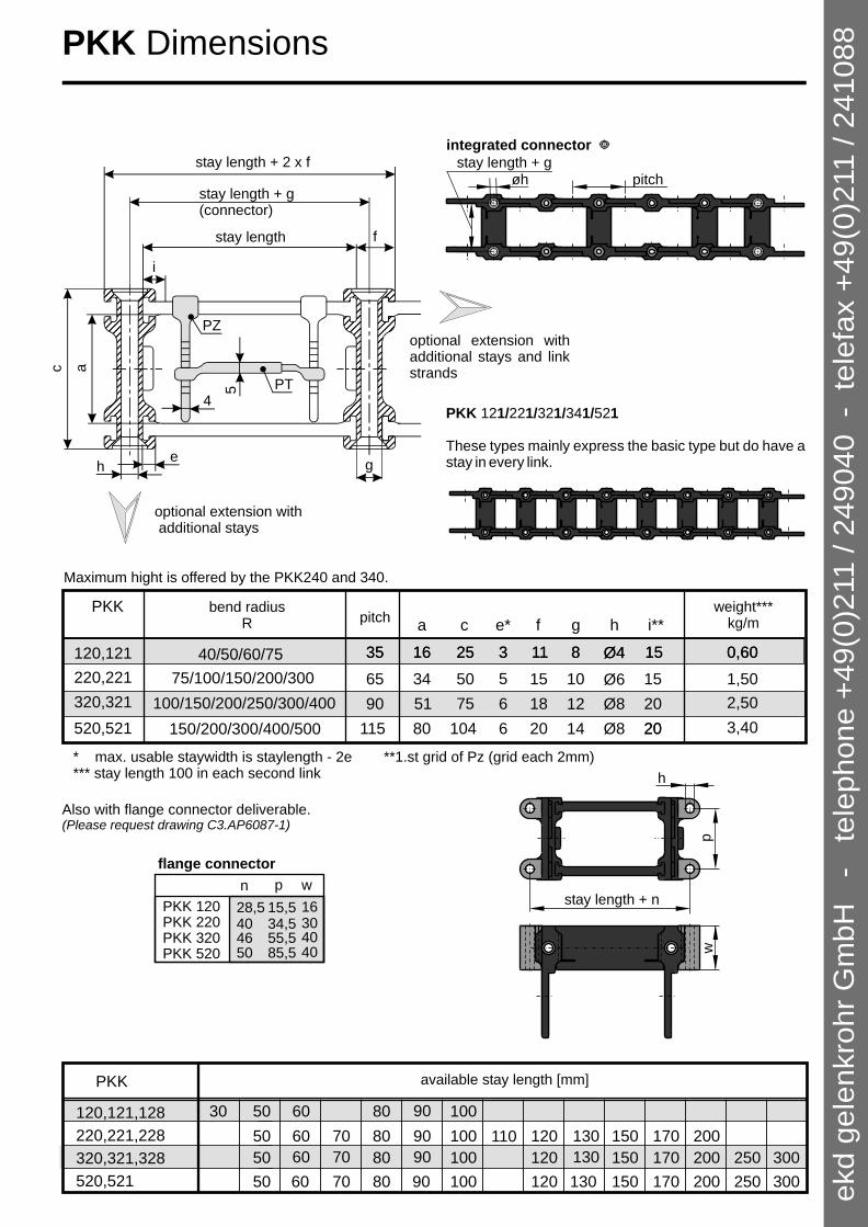
The order for a plastic energy chain PKK should contain the following data:
Type / Radius x Length / Width "Arrangement"; Separator arrangement
Type selection is in accordance with diameter and quantity of the lines to be installed. A clearance of at least 10 % for cables and 20 % for hoses should be available.
The R(adius) is also dependent on the cables to be installed. Comply with the statements of the manufacturer.10 times the largest line diameter can be chosen in general.
The L(ength) of the chain depends on the travel distance. The following formula can be used: L = travel distance /2 + (4x radius) (round up to link pitch)
The energy chain is delivered with additional connector links. (see drawing below)
The W(idth) of the chain depends on the number and dimension of the cables to be installed. With slow applications cables can be installed on top of one another, creating extra space.
The Arrangement is only to be stated in special cases. (see page 29)
The Separator arrangement depend on the application. (see example)
Example: Travel distance 3 m, bend radius 200 mm, cables: 1x15 mm, 8x8 mm, 3x12 mm, 2x22 mm
Plastic divider (PZ)
Plastic telescopic layer divider (PT)
11chain width + 50
cha
in h
igh
t =
2R
+ li
nk
hig
ht
50
min
.
RRca.0,5R
length L
0.5 travel distance 0.5 travel distancetravel distance
movable connector
fixed connector
supporting surface
pitch
pretension
øhstay length + g pitch
1
2
3
4
5
6
17
ekd g
ele
nkro
hr
Gm
bH
-
tele
phone +
49(0
)211 / 2
49040 -
tele
fax +
49(0
)211 / 2
41088
2
PKK 121/221/321/341/521
These types mainly express the basic type but do have a stay in every link.
integrated connector
øhstay length + g
pitch
p
h
stay length + n
w
n p
15,528,5PKK 120PKK 220 40 34,5
55,546PKK 320PKK 520 50 85,5
w
16304040
flange connector
Also with flange connector deliverable.(Please request drawing C3.AP6087-1)
PKK
120,121,128
220,221,228
320,321,328
30 50
50
50
60 70 80 90
80
100
100
100
120
120
150
150
170
250
200
200 30080
520,521 150 20050 100 12080 250 300
170
170
60
130
90
60 70 90 130
110
60 70 90 130
available stay length [mm]
120,121
65
90
115
75/100/150/200/300
150/200/300/400/500
35 0,60
1,50
2,50
PKK
220,221
320,321
520,521
100/150/200/250/300/400
40/50/60/75 35 0,60
3,40
* max. usable staywidth is staylength - 2e*** stay length 100 in each second link
pitchbend radius
Rweight***
kg/m
**1.st grid of Pz (grid each 2mm)
Maximum hight is offered by the PKK240 and 340.
i**
15
15
20
20
15
20
h
Ø4
Ø6
Ø8
Ø4
Ø8
g
8
10
12
14
8
f
11
15
18
20
11
e*
3
5
6
6
3
c
25
50
75
104
25
a
16
34
51
80
16
PZ
PT
i
g
5f
4
eh
c a
stay length + 2 x f
stay length
optional extension with additional stays
optional extension with additional stays and link strands
stay length + g(connector)
PKK Dimensions
18
ekd
ge
len
kro
hr
Gm
bH
-
t
ele
ph
on
e +
49
(0)2
11
/ 2
49
04
0 -
te
lefa
x +
49
(0)2
11
/ 2
41
08
8

LOAD DIAGRAM PKK
oa
dkg
)l
/ (
/m
free carrying length Lf / (m)
8
6
4
2
0 6 4 2
K 3
2P
K0
PK
K22
0
KK
12
P
0
PK
240
K
PK
K 3
04
PK
K 5
02
0
10
Lf
The professional assembly of the lines is prerequisite for a durable business. Detailed advice is necessary at high speeds, accelerations as well as at tubes. Notice the information from the line manufacturer (minimum bend radius, suitability for energy chains etc.) absolutely.
plastic telescopic layer divider (PT)
PKK 120/220/240/320/340/520
PKK can be combined to every width by using different lengths of stays. Chain may easily be extended or shortened without using any tools by removing the clip. Both stays in the inner and outer radius may be removed to load chain with cables. For separation of cables plastic dividers may be fixed in 2 mm steps as well as telescopic dividers for horizontal separation. Each link is supplied with its own connecting hole. No additional connecting pieces are necessary. The basic type has a stay every second link.
Load diagram:
The additional load is decisive for the choice of the energy chain next to minimum bend radius and maximum cable dimension. If the free carrying length is exceeded the next size must be chosen.
Plastic telescopic layer divider (PT)
PlasticIntermediate divider (PZ)
Plastic layer divider stay,overhung (PF)
Material:
The used polymer material is a very high-quality, glass fibre reinforced polyamide. The resistance against chemical substances is very good (exception acids and concentrated alkalines). Ask our technicians in doubt under detail of the used chemicals.The temperature range of application is between - 20° and +100° C. Advice is also required in the clean room, surge, or explosion endangered areas as well as areas with extreme environmental conditions (e.g. tropics).
Inner separation:
The highly variable divider distribution, the small step of 3 mm in the height setting rang and the telescopic layer dividers (PT) permit maximum flexibility for all requirements, also in case of retrospective changes.
remove stay
stay
type range in mm
PT 55 55 to 80 mm
PT 75 75 to 100 mm
PKK Characteristics
19
unlock stay
ekd
ge
len
kro
hr
Gm
bH
-
t
ele
ph
on
e +
49
(0)2
11
/ 2
49
04
0 -
te
lefa
x +
49
(0)2
11
/ 2
41
08
8

PKK 215
The PKK can, for optical reasons, also be delivered with smooth links. This option should be preferred, when ordering PKK closed type.
S by the closed t .
mooth links cause an excellent optical effectype
PKK
210, 211
240, 241
310, 311
340, 341
50 60 70 80 90 100 120 150 170 200130110
50 60 70 80 90 100 120 150 170 200130110
50 100 120 150 250200 30080 17060 70 90 130
50 100 120 150 250200 30080 17060 70 90 130
110, 111 50 60 80 90 10030
available stay lengths [mm]
*max. usable inner width is stay length - 2e**1.st grid of PZ (grid each 2mm)*** stay length 100 in every second link
a c he* f g i**a c he* f gPKK
i**
110, 111 35 40/50/60/75 0.60 10 8 3 Ø4 25 16 15
210, 211 6565/75/100/125/150/200/215/250/300 1,5010105 Ø65034 15
240, 241 75/100/150/200/250/300 65 10105 Ø66044 15 1,50
310, 311 100/130/150/200/300/400 2,5012126 Ø87551 2090
90100/150/200/300/400 Ø8340, 341 3,20151568560 20
pitchbend radiusR
weightkg/m
5
4
PZ
PT
i**
eh
c a
optional extension byadditional stays
stay length + 2 x f
stay length + g
(connector)
PKK 110/210/240/310/340 Smooth links
20
ekd
ge
len
kro
hr
Gm
bH
-
t
ele
ph
on
e +
49
(0)2
11
/ 2
49
04
0 -
te
lefa
x +
49
(0)2
11
/ 2
41
08
8

R
RPKK is used for extremely long travels. The chain bands are gliding on each other by using sliders. These are made of a special plastic with extremely good friction values. Only few wear will occur. Sliders may be pressed into connecting holes of links afterwards. Low numbers of strokes and travelling speed less than 1 m/s do not require sliders. The minimum bending radius of each chain type is not available with sliders.
very often
slider hight q:PKK128 = 3 mmPKK228 = 5 mmPKK228 = 8 mmPKK328 = 5 mm
friction value 0,2 bis 0,25
If the travel distance is longer than twice of the free carrying length, then a guiding of the energy chain is necessary. The assembly and putting into operation of the guiding channel should be done with the greatest care to ensure a smooth function of the system. Guiding channels for all fields of application are available. The single channel segments are fastened with connection elements. The moved part of the chain glides up to the half of the travel distance on the slide bar which is assembled at the channel segments. The exchange area is arranged to ensure a smooth transition to the energy chain. At travel distances up to app.30 m, travel speeds up to v = 1.5 m/s and accelerations of a = 1 m/s ² max maxenergy chain and channel can be realized like in the enclosed drawing. Applications at higher values request for advise to satisfy the special requirements by specific constructions.
Usual assembly situation:
Energy chain connection at the moved end lower assembled and with an additional length at the end of the travel distance:
end position I
slide bar
(application example)
intermediate position
end position II
additional length
slide bar
3 q
PKK 128/228/328 Slider
21
ekd
ge
len
kro
hr
Gm
bH
-
te
lep
ho
ne
+4
9(0
)211
/ 2
49
04
0 -
te
lefa
x +
49
(0)2
11
/ 2
41
08
8

1. unlock hooks2. remove cover plate
hook cover plate
hook
a
n
r
s
These are the closed types of PKK. To install cables coverplates both in the outer and inner radius may be removed. Plastic dividers and plastic layer dividers may also be supplied to separate cables. Basic chain type can be changed into closed type simply by using cover plates instead of stays.The PKK can also be delivered with smooth links which safes space and causes an excellent optical effect.
PKK 213/223/243/313/323 do have an additional stay in the inner radius. It can be used in case of low travelling speed to get more space for additional layers of cables. Additional stays may also be placed in the outer radius. Other combinations can be delivered by request.
PKK
213, 223
243
50
50
60 70 80 90 100
100
120
120
150
150
170 200
20080
313, 323 150 20050 100 12080 250 300
170
170
130
60 70 90 130
110
60 70 90 130
110
available stay lengths [mm]
PKK add. stay n r s
213,223, short 19,5 14,5 -
243 long 39 - 34
313,323 short 29,5 21,5 -
long 59 - 51
PKK215
PKK 125/225/245/325/345/525 Closed type
PKK 213/223/243/313/323 Additional stays
22
PKK
125
225, 215
325, 315
50
50
100
100 200150
50
100
100 150 200 300
345 150 200
150
200
245 50 100 200150150
525 150 200200
100 300
available cover plates (lengths)min. Radius
ekd
ge
len
kro
hr
Gm
bH
-
te
lep
ho
ne
+4
9(0
)211
/ 2
49
04
0 -
te
lefa
x +
49
(0)2
11
/ 2
41
08
8

chain width + 20
2x
R +
lin
k h
eig
ht
20
min
support
fixed connector
pitch
movable connector
ca. 0,5 R
R
0,5 travel
0,5 travel
travel
length L
Kolibri 13.0 / 200 x 2.310 "h"; 3 PZ 4th link
1
2
3
4
Kolibri Energy chains
Type / Radius x Length "Arrangement”; Separators
The following information is required to proceed with your order:
The Type is determined by number and diameter of cable andhoses. Allow 10% space for cables and 20% for hoses.
The R(adius) is determined by the the bending radius of the cable and Hoses. 10 x diameter would always be a good advice.
Chain length is depending on travel. The following formula applies:half of travel distance + 4 x radius.
The Arrangement is only required in special cases. (see page 29)
The Separator arrangement depend on the requirements. (see example)
Example: travel 3m, bending radius 200mm, 1 cable 15mm + 3 cable 18mm, PZ (pinch stay) vertical hanging arrangement; separators: 3 PZ each 4th link
All Kolibri chains are supplied with the integrated plasticconnector. Each link can be the end connector:
Front flange connectors are available for several Kolibri types (see page 28):
Material:Polyamide glass fibre reinforced. Excellent resistance against chemical materials.(Except acid and concentrated lye)Temperature - 20° up to + 100° Celsius in long term operation. For more informationplease contact our experienced technical staff.
23
5
ekd
ge
len
kro
hr
Gm
bH
-
t
ele
ph
on
e +
49
(0)2
11
/ 2
49
04
0 -
te
lefa
x +
49
(0)2
11
/ 2
41
08
8

He
be
n
h
0,5 pitch
g
0,5 pitch
He
be
n
He
be
n
h
0,5 pitch
g
0,5 pitch
0,5 pitch0,5 pitch
h
g
inner radius
bd
a c
pitchb
c
d
a
pitch
d
c
Ø 10pitch
R a b c d g h kg / m
bend radius pitch inner dim. outer dim. connecting dim. weight
Kolibri 02 20 / 30 20 15 37 30 4 0,20
Kolibri 05 30 18 25 22 38 31 4 0,34
10 24
Kolibri 01 20 / 30 20 15 22 15 4 0,15
Kolibri 1 40/100/200 40 24 18 30 30 23 4 0,5
Kolibri 2 40/100/150/200 40 24 48 30 60 53 4 0,6
Kolibri 3 40/100/200 40 24 78 30 90 83 4 0,7
Ø 10
Kolibri 03 20 / 30 20 10 39 15 51 44 4 0,28
Kolibri 06 30 18 36 22 48 41 4 0,37
35 / 70
35 / 70
R c d g h kg / m
Kolibri 0 17,5 / 20 / 30 20 Ø 10 15 15 15 4 0,13
bend radius pitch inner dim. outer dim. connecting dim. weight
Kolibri 0
Kolibri 01 / 1 / 2 / 3 Kolibri 02 / 03 / 05 / 06
Kolibri 01 is identical withconnecting part for Kolibri 0
smallest dimensionseasily extendable and shortableintegrated end connectorshighly rigid and wear resistant
Kolibri 0 / 01 / 1-3 / 02-06 Dimensions
24
ekd
ge
len
kro
hr
Gm
bH
-
t
ele
ph
on
e +
49
(0)2
11
/ 2
49
04
0 -
te
lefa
x +
49
(0)2
11
/ 2
41
08
8

25
Pinch stay and horizontal stay:The pinch stay and the horizontal stay allow quick and easy separation. Even for cable loaded chain.Pinch stay with 4mm thickness require PT 55 or PT 75 (see page 20) for horizontal separation.
bend radius pitch inner dim. outer dim. divider / connector weight
R a b c d e g h i kg/m
Kolibri 10.0 40/75/100/150/200 35 23 34 30 50 3 40 5 9,5 0,54
Kolibri 11.0 40/75/100/150/200 35 23 44 30 60 3 50 5 9,5 0,61
Kolibri 12.0 40/75/100/150/200 35 23 64 30 80 3 70 5 9,5 0,65
Kolibri 13.0 40/75/100/150/200 35 23 79 30 95 3 85 5 12 0,75
Kolibri 14.0 40/75/100/150/200 35 23 109 30 125 3 115 5 12 0,87
Kolibri 15.0 60/75/100/150/200 45 29 47 40 62 4 54 5 7,5 1,05
Kolibri 16.0 60/75/100/150/200 45 29 60 40 75 4 67 5 7,5 1,30
Kolibri 17 60/100/125/250 50 30 109 40 125 2 115 5 12 1,30
Kolibri 19.0 75/100/150/175/200 55 40 78 50 95 2 85 6 6,5 1,35
Kolibri 20.0 75/100/150/200/250 55 40 133 50 150 3 140 6 12,5 1,57
Kolibri 21.0 75/100/150/200/250 55 40 48 50 65 2 55 6 9 1,30
Kolibri 22.0 75/100/150/200/250 55 40 108 50 125 3 115 6 6,5 1,52
Kolibri 29.0 100/125/150/200/300 70 50 205 65 225 4 215 6 17,5 2,71
easy access by flap open barsintegrated end connectorsextremely rigid and wear resistantunique separation with the pinch stay
Assembling adviceOpening: - unlock bar by lifting from gap- open by pushing bar slightly sidewaysClosing:- simply press down bar And lock
Kolibri 10.0 - 29.0 Dimensions
Countersink for opticalreasons or by sliding chain application
90°
inner radius
db
a c
0.5pitch 0.5pitch
h
g5
8.5
60
8x5=40
8.5
3
e
i
2.5
pitch
ekd
ge
len
kro
hr
Gm
bH
-
t
ele
ph
on
e +
49
(0)2
11
/ 2
49
04
0 -
te
lefa
x +
49
(0)2
11
/ 2
41
08
8

d
b
a c
outer radius
pitch90°
Pinch stay and horizontal stay:The pinch stay and the horizontal stay allow quick and easy separation. Even for cable loaded chain.Pinch stay with 4mm thickness require PT 55 or PT 75 (see page 20) for horizontal separation.
Assembling adviceOpening: - unlock bar by lifting from gap (1,2)- open by pushing bar slightly sideways (3)
Closing:- simply press down bar And lock
8.5
60
8x5=40
8.5
3
e
i
2.5
1
2
3
0.5pitch
h
g
10
0.5pitch
bend radius pt. inner dim. outer dim. connector weightR a b c d g h kg / m
Kolibri 02.5 18 10 24 15 36
Kolibri 07.5 26 17 48 22 60
Kolibri 10.5 60/75/100/150/200 35 21 34 30 50 40 5 0,65
Kolibri 15.5 45 30 48 40 62
Kolibri 19.5 100/150/200/250 55 38 78 50 95 85 6 1,50
Kolibri 20.5 100/150/200/250 55 38 134 50 150 140 6 1,90
Kolibri 21.5 55 38 48 50 65 55 6
Kolibri 24.5 70 50 77 65 95 85 6
Kolibri 25.5 70 50 117 65 135 125 6
2,20
100/150/200/250
125/150/200/300
125/150/200/300
Kolibri 27.5 70 50 177 65 195 185 6125/150/200/300
1,30
e
2
2
2
2
4
4
4
50 / 70 / 100
30 / 50
2,60
3,00
30 4 0,28
75/100/150/200 54 5 0,912
53 4 0,54
26
hinged covershigh rigidityintegrated end connector
Kolibri 02.5 - 27.5 Closed type
countersink for opticalreasons or by sliding
ekd
ge
len
kro
hr
Gm
bH
-
t
ele
ph
on
e +
49
(0)2
11
/ 2
49
04
0 -
te
lefa
x +
49
(0)2
11
/ 2
41
08
8

0.5 pitch 0.5 pitch
g
h
b
a
d
c
pitch
Kolibri 00.3 / 0.3 / 04.3 Film stay
27
00 3.
8
6
4
2
loa
d / (
kg
/m)
10
0
LOAD DIAGRAM Kolibri
ol.
1-
/ .
-1
K
3
10
04
.015.
17
Kol.
0-
19.
21.
Kol.
0-
5ol.
24.5
29.0
K
-
05
//
Kol.
0
6
07.5
1 /
Kol. 0
/ 02
03
2 3 1 0
free carrying Lf / (m)
Lf
openable in inner radiusrigid design for small chains
bend radius pitch inner dim. outer dim. connector weight
R a b c d g h kg / m
Kolibri 0.3 20 / 30 20 15 15 15 4 0,10
15 / 30 / 50 15 Ø 7 10 12 12 3 0,06
35 / 70 / 100 30 17 15 22 25 19,4 4 0,20
Ø 10
Kolibri 00.3
Kolibri 04.3
ekd
ge
len
kro
hr
Gm
bH
-
t
ele
ph
on
e +
49
(0)2
11
/ 2
49
04
0 -
te
lefa
x +
49
(0)2
11
/ 2
41
08
8

5,2
20
12
27
10
10
30L 72 92 107 13762
Kolibri 10.0 Kolibri 11.0 Kolibri 12.0 Kolibri 13.0 Kolibri 14.0
27,5
59 62.5L
10
24 5,2
55
107 6 147 207
Kolibri 24.5 Kolibri 25.5 Kolibri 27.5
22,5
42,5
15
50L
10
107 137 162
,25
77
40
Kolibri 21.0 + 21.5
Kolibri 19.0 + 19.5
Kolibri 22.0
Kolibri 20.0 + 20.5
6
15
30
13
10
33L 62
5,2
Kolibri 10.5
6
14
31,5
12
30
39,5L 74
5,2
10
6
Kolibri 15.5
8
20
7 5
21
5 2,
9
Kolibri 05.0 Kolibri 07.5
7048L
10
7
14
Kolibri 02.5
4,5
15,5
5
46
5,2
L
28
Kolibri Front flange connector
ekd
ge
len
kro
hr
Gm
bH
-
t
ele
ph
on
e +
49
(0)2
11
/ 2
49
04
0
- t
ele
fax +
49
(0)2
11
/ 2
41
08
8

29
B
FF
B
suo l
pp rt oad
de
nep nde t
F
B
support load
de end ntp
e
B
F
B
B
F
B
normal (no order comment) "s" standing (without pretension) "h" hanging (without pretension)
"w" horizontal, laying on side (without pretension)
"u" moved end downside
"m" multiaxial
"i" into each other
"f" free overhung"k" circular, laying on side
B
B = moved connector
F = fixed connector (mid of travel)
F
F
BF
F
Arrangements
B
FF
B
suo l
pp rt oad
de
nep nde t
F
B
support load
de end ntp
e
B
F
B
B
F
B
normal (no order comment) "s" standing (without pretension) "h" hanging (without pretension)
"w" horizontal, laying on side (without pretension)
"u" moved end downside
"m" multiaxial
"i" into each other
"f" free overhung"k" circular, laying on side
B
B = moved connector
F = fixed connector (mid of travel)
F
F
BF
F
There are basic drawings for CAD users in different file formats, which can be imported in existing drawings. Please request or download.
3D-CAD files will be offered on request:
Telefon: +49 (0) 211 / 24904 - 0Telefax: +49 (0) 211 / 241088
EDITION 11/2008
ekd g
ele
nkro
hr
Gm
bH
-
tele
phone +
49(0
)211 / 2
49040 -
tele
fax +
49(0
)211 / 2
41088


![K EKD WZ EKD^ v ] v](https://img.pdfslide.net/doc/110x75/618d3715a4cce022c34457e9/k-ekd-wz-ekd-v-v.jpg)